

Page 1
CED Series 1500
Operation Manual
Lancer Corporation
6655 Lancer Blvd.
San Antonio, Texas 78219
800-729-1500
“Lancer” is the registered trademark of Lancer © 2016 by Lancer, all rights reserved.
1500
Technical Support/Warranty
800-729-1550
custserv@lancercorp.com
lancercorp.com
PN: 28-0450/02
1
Page 2
TABLE OF CONTENTS
ABOUT THIS MANUAL
This booklet is an integral and essential part of the product.
Please carefully read the guidelines and warnings contained
herein as they are intended to provide the user with essential
information for the continued safe use and maintenance of the
product. In addition, it provides GUIDANCE ONLY to the user
on the correct services and site location of the unit.
The installation and relocation, if necessary, of this product must be carried out by qualied personnel with
up-to-date safety and hygiene knowledge and practical experience, in accordance with current regulations.
IMPORTANT SAFETY INSTRUCTIONS.......................3-4
Intended Use..............................................................3
Power Warning...........................................................3
CO2 Warning...............................................................3
Water Notice...............................................................3
Agitation Warning........................................................4
SPECIFICATIONS AND FEATURES............................4-5
General System Overview..........................................5
PRE-INSTALLATION CHECKLIST...................................5
INSTALLATION...........................................................6-10
Unpacking the Dispenser............................................6
Selecting/Preparing a Counter Location.....................6
Dispenser Installation..............................................7-8
Installing Remote Syrup Pumps - BIB........................8
Connecting to Syrup Supply - BIB..............................9
Installing CO2 Supply / Dispenser Setup...............9-10
Adjust Water Flow Rate & Syrup/Water Ratio..........10
BEFORE GETTING STARTED
Each unit is tested under operating conditions and is thoroughly
inspected before shipment. At the time of shipment, the
carrier accepts responsibility for the unit. Upon receiving the
unit, carefully inspect the carton for visible damage. If
damage exists, have the carrier note the damage on the freight
bill and le a claim with carrier. Responsibility for damage to the
dispenser lies with the carrier.
MAINTENANCE..............................................................11
Scheduled Maintenance...........................................12
CLEANING AND SANITIZING..................................11-12
General Information..................................................11
Cleaning and Sanitizing Solutions............................12
Cleaning and Sanitizing Syrup Lines........................12
Cleaning and Sanitizing Nozzles..............................12
TROUBLESHOOTING...............................................13-17
THE ELECTRONIC ICE BANK CONTROL (EIBC).......18
Checking the Normal PCB Operation.......................18
ILLUSTRATIONS AND PART LISTINGS..................20-29
Cabinet Assembly - High Performance...............20-21
Cabinet Assembly - 1500E and Pre-Mix..............22-23
Refrigeration Deck Assembly - USA...................24-25
Refrigeration Deck Assembly - Export.................26-27
Wiring Diagram - USA..............................................28
Control Housing Connections...................................28
Wiring Diagram - International..................................29
Plumbing Diagram - 5 Valve and 6 Valve.................29
READ ALL SAFETY INSTRUCTIONS BEFORE USING THIS UNIT.
This manual contains important safety information and all applicable safety precautions must be observed. To reduce
the risk of re, electric shock, damage to the equipment or personal injury when using this unit all instuctions/warnings
on the product being used must be followed:
! WARNING
Text following the Warning signal indicates a
hazardous situation, which if not avoided, will result
in death or serious injury. Be sure to read all Warning
statements before proceeding with the installation.
! CAUTION
Text following the Caution signal indicates a
hazardous situation, which if not avoided, could result
in death or serious injury. Be sure to read the Caution
statements before proceeding with the installation
2
SAFETY NOTICES
! ATTENTION
Text following the Attention signal addresses a
situation that if not followed could potentially damage
the equipment. Be sure to read the Attention
statements before proceeding
NOTE
Text following the Note signal provides you with
informationthatmayhelpyoumoreeectivelyperform
the installation procedures within this manual.
Disregarding information will not cause damage or
injury, however it may limit the performance of the
dispenser.
Page 3
IMPORTANT SAFETY INSTRUCTIONS
! Intended Use
• The dispenser is for indoor use only
• This appliance is intended to be used in commercial
applications such as restaurants or similar.
• This appliance should not be used by children or
inrm persons without supervision.
• This appliance is not intended for use by persons
(including children) with reduced physical, sensory
or mental capabilities, or lack of experience and
knowledge, unless they have been given supervision
or instruction concerning use of the appliance by a
person responsible for their safety.
• This appliance can be used by children aged from 8
years and above and persons with reduced physical,
sensory or mental capabilities or lack of experience
and knowledge if they have been given supervision or
instruction concerning use of the appliance in a safe
way and understand the hazards involved.
• Cleaning and user maintenance shall not be
performed by children without supervision.
• This unit is not a toy and children should be advised
not to play with the appliance.
• The min/max ambient operating temperature for the
dispenser is 40°F to 90°F (4°C to 32°C).
• Do not operate unit below minimum ambient operation
conditions.
• Should freezing occur, cease operation of the unit and
contact authorized service technician.
• The maximum tilt for safe operation is 5°.
• This appliance must be installed and serviced by a
professional.
5 Carbon Dioxide (CO2)
• WARNING: Carbon Dioxide (CO2) is a colorless,
noncombustible gas with a light pungent odor. High
percentages of CO2 may displace oxygen in the
blood.
• WARNING: Prolonged exposure to CO
Personnel exposed to high concentrations of CO2 gas
will experience tremors which are followed by a loss
of consciousness and suocation.
• WARNING: If a CO
ventilate the contaminated area before attempting to
repair the leak.
gas leak is suspected, immediately
2
• WARNING: Strict attention must be observed in the
prevention of CO2 gas leaks in the entire CO2 and soft
drink system.
can be harmful.
2
F Power
• Follow all local electrical codes when making
connections.
• Check the dispenser name plate label, located behind
the splash plate for correct electrical requirements of
unit. DO NOT plug into a wall electrical outlet unless
the current shown on the serial number plate agrees
with local current available.
• Each dispenser must have a separate electrical
circuit.
• DO NOT use extension cords with this unit.
• DO NOT ‘gang’ together with other electrical devices
on the same outlet.
• WARNING: Always disconnect electrical power to the
unit to prevent personal injury before attempting any
internal maintenance.
• The resettable breaker switch should not be used as
a substitute for unplugging the dispenser from the
power source to service the unit.
• Only qualied personnel should service internal
components of electrical control housing.
• WARNING: Make sure that all water lines are tight and
units are dry before making any electrical connections
• If this dispenser is installed in an area that is
susceptible to ±10% variation of the nominal line
voltage, consider installing a surge protector or similar
protection device.
! Water Notice
• Provide an adequate, potable water supply. Water
pipe connections and xtures directly connected to
a potable water supply must be sized, installed, and
maintained according to federal, state, and local
codes.
• The water supply line must be at least a 3/8 inches
(9.525 mm) pipe with a minimym of 25 PSI (0.172
MPA) line pressure, but not exceeding a maximum of
50 PSI (0.345 MPA). Water pressure exceeding 50
PSI (0.345 MPA) must be reduced to 50 PSI (0.345
MPA).
• Use a lter in the water line to avoid equipment
damage and beverage o-taste. Check the water lter
periodically, as required by local conditions.
• CAUTION: The water supply must be protected by
means of an air gap, a backow prevention device
(located upstream of the CO2 injection system)
or another approved method to comply with NSF
standards. A leaking inlet water check valve will
allow carbonated water to ow back through the pump
when it is shut o and contaminate the water supply.
• CAUTION: Ensure the backow prevention device
complies with ASSE and local standards. It is the
responsibility of the installer to ensure compliance.
3
Page 4
! Automatic Agitation
25 3/8 "
64.45 cm
18 3/4 "
47.63 cm
24 "
60.96 cm
19 3/16 "
48.74 cm
9 1/2 "
24.13 cm
3 1/2 "
8.89 cm
• Units are equipped with an automatic agitation system and will activate unexpectedly.
• CAUTION: Do not place hands or foreign objects in the water bath tank. Unplug the dispenser during servicing, cleaning, and
sanitizing.
• CAUTION: To avoid personal injury, do not attempt to lift the dispenser without assistance. For heavier dispensers, use a
mechanical lift.
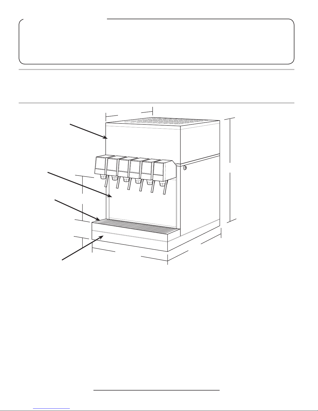
PRE-INSTALLATION
Specications & Features
A
B
C
D
DIMENSIONS
Width: 19.2 inches (487 mm)
Depth: 24 inches (610 mm)
Height (w/out legs): 25.4 inches
(645 mm)
WEIGHT
Shipping: 150 lbs (68.2 kg)
Empty: 130 lbs (59.0 kg)
Operating: 220 lbs (99.8 kg)
ELECTRICAL
A. Bonnet
B. Splash Plate
C. Cup Rest
D. Drip Tray
ICE BATH
Capacity: 30.0 lbs (13.6 kg)
PLAIN WATER SUPPLY
Min Flowing Pressure: 25 PSIG (0.172 MPA)
Max Static Pressure: 50 PSI (0.345 MPA)
CARBON DIOXIDE (CO2) SUPPLY
Min Pressure: 70 PSIG (0.483 MPA)
Max Pressure: 80 PSIG (0.552 MPA)
FITTINGS
115 VAC / 60 Hz / 4.5 Amps
230 VAC / 50 Hz / 4.5 Amps
4
This unit emits a sound pressure level below 70 dB
Water Inlet: 3/8 inch barb
Brand Syrup Inlets: 3/8 inch barb
CO2 Inlet: 3/8 inch barb
Page 5
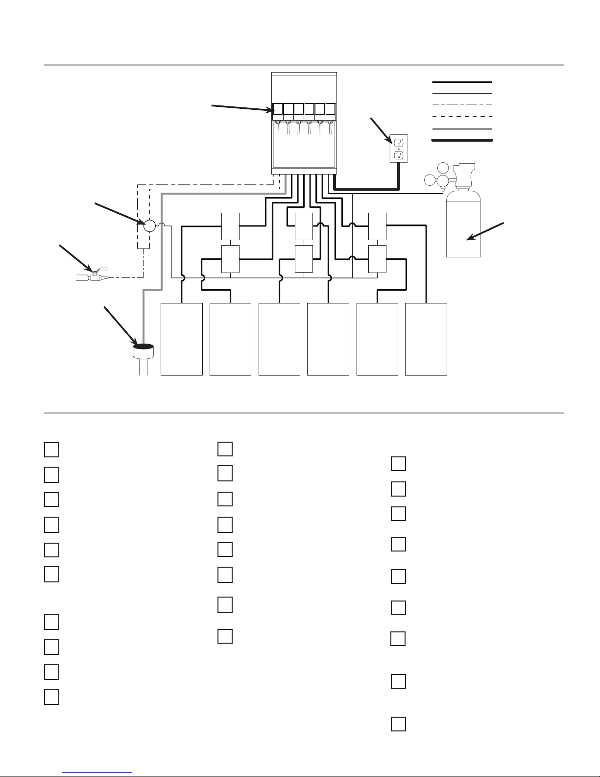
General System Overview
F
B
Syrup Line
CO2 Line
G
Plain Water Line
Carb Water Line
Drain Line
Electrical
A
C
D
Pre-Installation Checklist
TOOLS REQUIRED:
Oetiker Pliers
Tubing Cutters
Wrench
Slotted Screwdriver
Phillips Screwdriver
E E
E E
D
D
D
POST MIX ACCESSORIES:
CO2 Regulator
CO2 Supply
Chain for CO2 Tank
Beverage Dispenser
Beverage Tubing
E
E
A. Water Source
B. Remote Carbonator
C. Floor Drain
D. BIB Syrup Containers
D
D
E. Syrup Pump
F. Dispenser
G. Electrical Outlet
H. CO2 Source
H
CONSIDER THE FOLLOWING
BEFORE INSTALLATION:
Location of Water Supply Lines
Location of Drain
Location of Electrical Outlet
Location of Heating and Air
Conditioning Ducts
Drill
BIB SYSTEM:
BIB Rack
BIB Syrup Boxes
BIB Regulator Set
BIB Connectors
Oetiker Clamp Fittings
Water Booster (Lancer PN:
82-3401 or MC-163172
Water Regulator (recommended)
Do you have enough space to
install the dispenser?
Is countertop level?
Can the countertop support the
weight of the dispenser?
Is dispenser located away from
direct sunlight or overhead
lighting?
Not in area where water jet could
be used.
5
Page 6
INSTALLATION
Read This Manual
This manual was developed by Lancer Corporation as a reference guide for the owner/operator and installer
of this dispenser. Please read this manual before installation and operation of this dispenser. Please see
pages 13-17 for troubleshooting or service assistance. If the service cannot be corrected please call your
Service Agent or Lancer Customer Service. Always have your model and serial number available when you
call.
Unpacking the Dispenser
1. Remove top portion of carton by lifting up.
2. Remove top inner carton pad and corners.
3. Remove accessory kit of loose parts from drip tray.
4. Lift unit up by plywood shipping base and remove lower
portion of carton.
NOTE
Inspect unit for concealed damage. If evident, notify
deliveringcarrierandleaclaimagainstthesame.
5. Remove splash plate.
NOTE
Splash plate is located under unit on shipping base for
Series 1500E models only
Selecting/Preparing a Counter Location
NOTE
The dispenser should only be installed in a location
where it can be overseen by trained personnel
1. The dispenser is designed to sit on a at, supported surface
capable of supporting a minimum weight of 400 lbs (182
kg). Select a location that is in close proximity to a properly
grounded electrical outlet, within ve (5) feet (1.5 m) of
a drain, and a water supply that meets the requirements
shown in the Specications section found on page 4.
2. Select a location for the syrup pumps, CO2 tank, syrup
containers, water lter (recommended), and remote
carbonator. Please see General System Overview on page
5 for reference.
3. The dispenser may either be counter or leg mounted. When
the dispenser is to be permanently bolted to the counter
top, use Lancer Sealant Kit (PN 15-0010) to seal dispenser
base to counter top.
6. Remove plywood shipping base from unit by moving unit so
that one side is o the counter top or table allowing access
to screws on the bottom of the plywood shipping base.
NOTE
If unit is to be transported, it is advisable to leave the
unit secured to the plywood shipping base.
7. If leg kit has been provided, assemble legs by tilting unit.
! ATTENTION
DO NOT LAY UNIT ON ITS SIDE OR BACK. DO NOT
USE DRIP TRAY FRAME FOR A HANDLE.
8. Remove accessory kit of loose parts from drip tray.
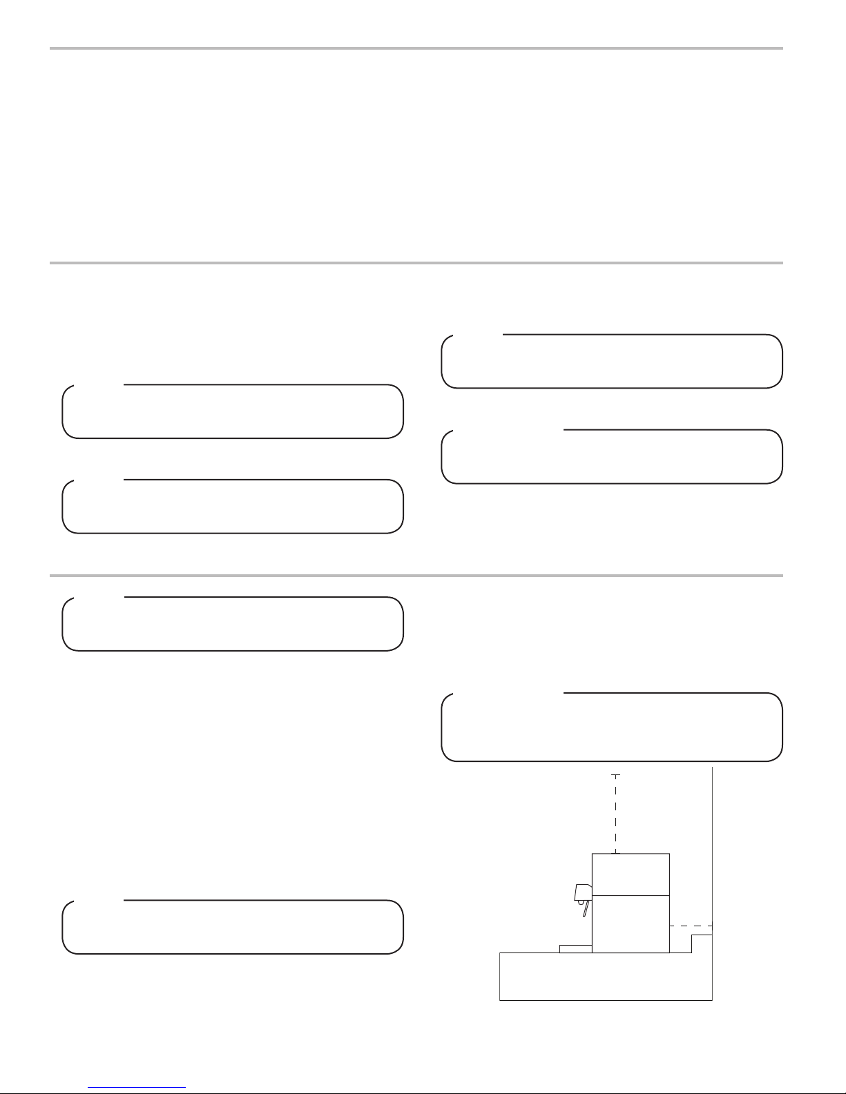
4. Condenser air is drawn in from the back grill located on the
bonnet and discharged out the top of the bonnet. A mini-
mum of fteen (15) inches (380 mm) of clearance must be
maintained over the top of the unit and a minimum of six (6)
inches (152 mm) clearance behind the unit to provide for
proper air ow and circulation.
! ATTENTION
Failuretomaintainspeciedclearancewillcausethe
compressor to overheat and will result in compressor
failure
15”
NOTE
NSF listed units must be sealed to the counter or have
four (4) inch legs installed.
6
6”
5. Cut the necessary holes in counter for mounting in the
designated dispenser location, using the template provided.
Page 7
Dispenser Installation
1. Install the unit onto the counter.
2. Remove the bonnet from the dispenser by lifting up.
3. Remove the drip tray from the unit and connect the drain
tube to the drain tting located on the bottom. Secure drain
tube with clamp provided in accessory kit.
4. Route the drain tube to a suitable drain and replace the
unit’s drip tray.
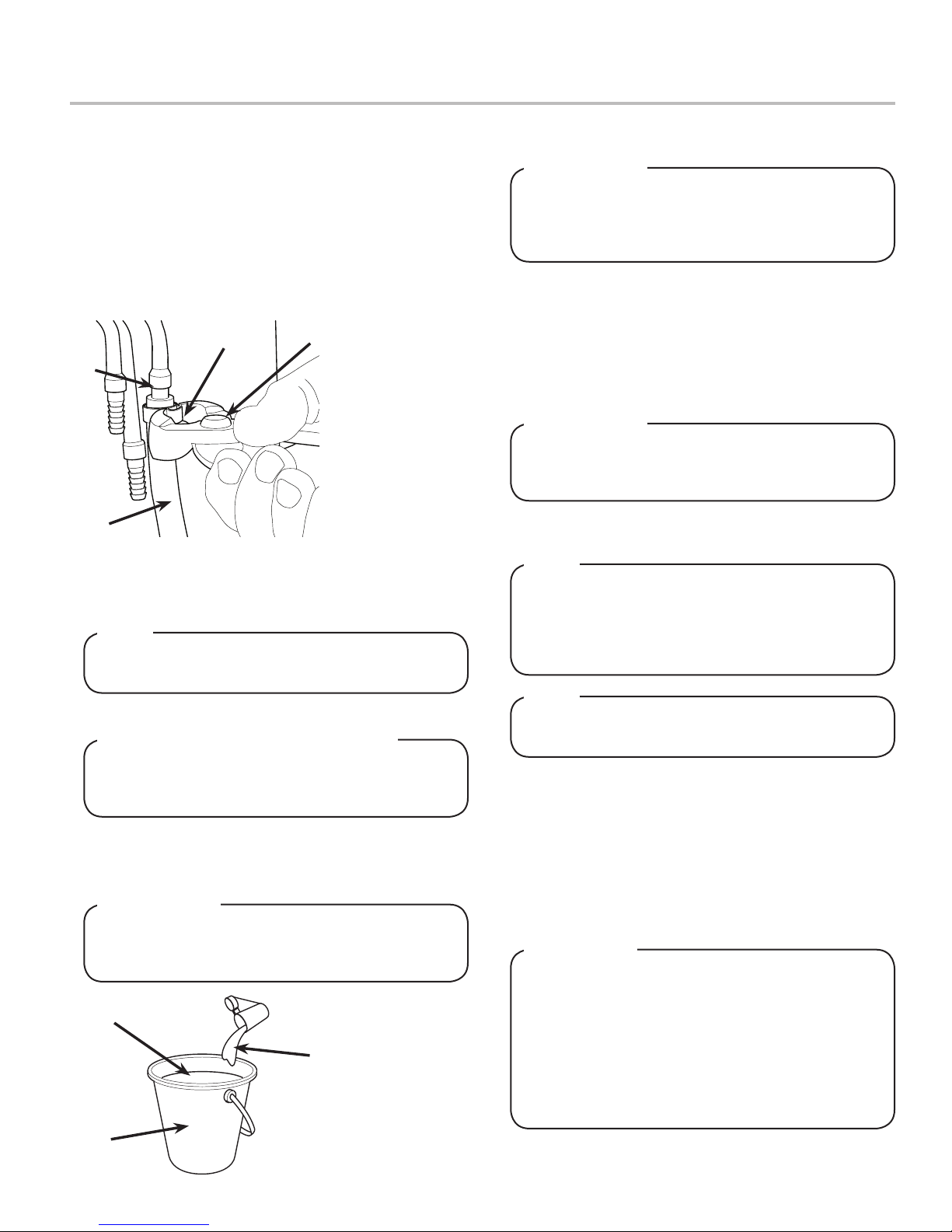
5. Route appropriate tubing from the syrup pump location to
the syrup inlets. Connect tubing to inlets using the oetiker
pliers and ttings. Repeat for all syrup connections.
B
A
D
A. Oetiker Pliers
B. Fitting
C. Tubing
D. Syrup/Water/CO2
C
6. Install remote carbonator per manufacturer’s instructions.
7. Route appropriate tubing from the water source to the
compressor deck ll hole, identied by the yellow cap, and
ONLY connect tubing to water source.
Inlet
NOTE
Leave 12 inches (305 mm) of extra tubing below the
counter for servicing and moving the dispenser
8. Flush water supply line thoroughly.
! CRITICAL - to maximize performance
Carefullyreadthisbeforellingthewaterbathtank.
In order to optimize the maximum performance of the
dispenser, the following MUST be adhered to:
9. Insert water line into a large bucket, and ll with approx. 5.4
gallons (20.4 L) of distilled water.
10. Add 1/8 oz (4 g) of baking soda to distilled water and stir.
! ATTENTION
Forproperfunctionoftheelectronicicebankcontrol
the total dissolved solids (TDS) measurements should
be 300-500 ppm.
B
C
A. Bucket
B. Distilled Water
A
(approx. 5.4 gal)
C. Baking Soda
(approx. 1/8 oz)
11. Using a conductivity meter, measure the electric
conductivity of the distilled water mixture.
! ATTENTION
The E.C. measurement of the distilled water mixture
must be between 100 and 300 uS/cm. Below 100 uS/cm,
thecompressorwillnotworkproperlyandabove300
uS/cm could cause the lines to freeze.
12. Remove yellow cap from the water bath ll hole and insert
and insert a funnel into the ll hole.
13. Remove the insulation strip from front of the refrigeration
deck.
14. Carefully pour the distilled water mixture into the water bath
tank until water ows out of the overow tube at the front of
the unit. (Repeat steps 9-11 if needed)
! ATTENTION
Thewaterbathcompartmentmustbelledwithwater
before plugging in the unit, otherwise the compressor
fan may not operate properly.
15. Replace yellow cap, replace insulation, then connect water
line to the water inlet in the front of the unit.
NOTE
Valves 2, 3, and 4 (on 5 valve units) and valves 3, 4,
and 5 (on 6 valve units) have optional plain water
or carbonated water capabilities. Use the Plumbing
Diagram on page 29 to determine which valves are to
be plumbed with plain water or carbonated water.
NOTE
Leave 12 inches (305 mm) of extra tubing below the
counter for servicing and moving the dispenser
16. Route appropriate tubing from the syrup pump location to
the carbonator CO2 inlet and connect tubing to CO2 inlet.
17. Re-attach splash plate and cup rest.
18. Plug in power cord to the unit control box.
19. Feed all tubing, power cord, and drain line through the
counter top cutout.
20. Plug in the unit to a grounded electrical outlet then turn the
unit on to begin building an ice bank.
! WARNING
The dispenser must be properly electrically grounded
toavoidseriousinjuryorfatalelectricalshock.The
power cord has a three-prong grounded plug. If a
three-hole grounded electrical outlet is not available,
use an approved method to ground the unit. Follow
alllocalelectricalcodeswhenmakingconnections.
Each dispenser must have a separate electrical circuit.
Do not use extension cords. Do not connect multiple
electrical devices on the same outlet.
7
Page 8
Installing Remote Syrup Pumps - Bag In Box
1. Install BIB rack and remote pumps according to
manufacturers’ instructions.
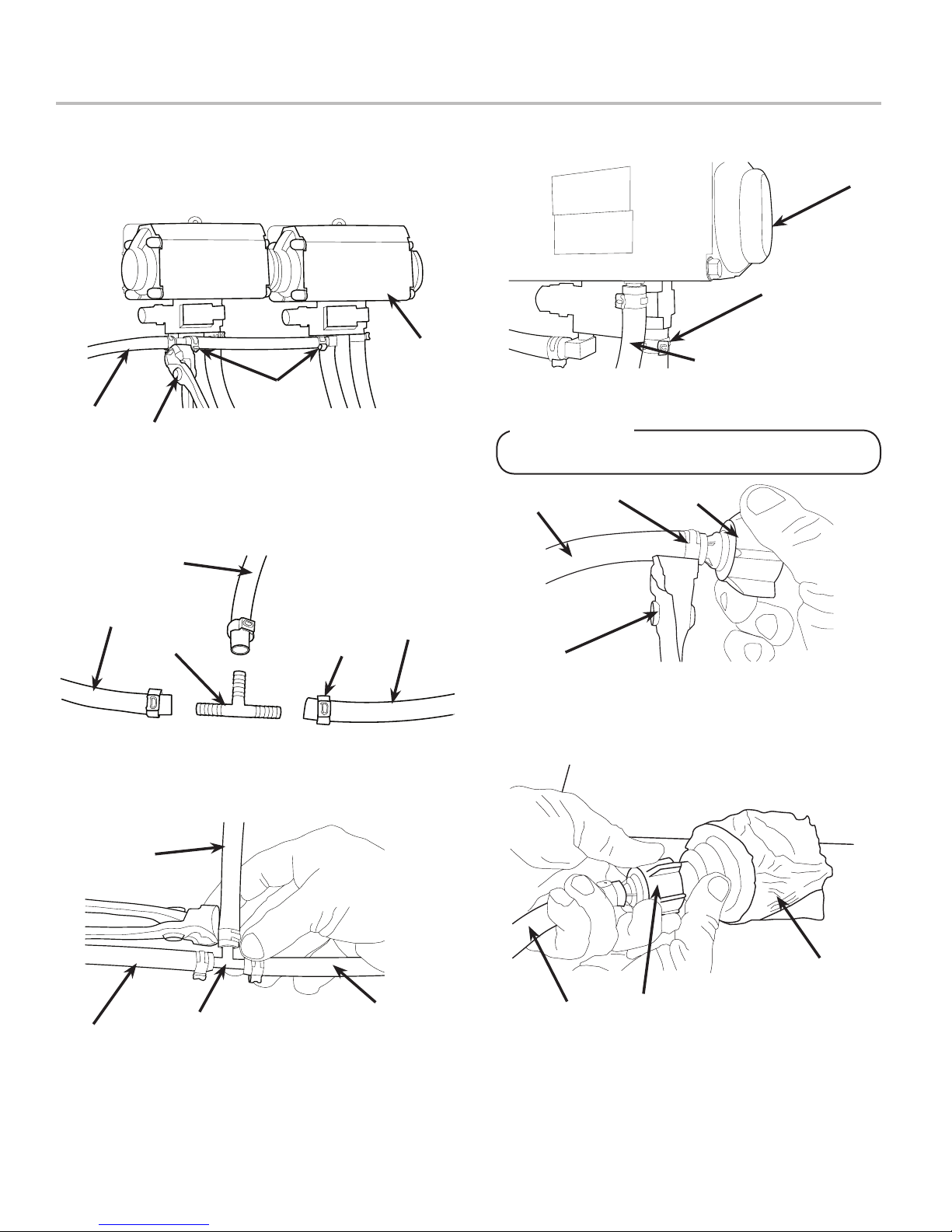
2. Once pumps and BIB rack are installed, measure and cut
tubing to length between the pump CO2 inlets, then connect
tubing to all pumps.
A
C
B
D
3. Using tubing cutters, cut any pump CO2 supply line and
install tee tting, then route appropriate tubing from the CO2
supply to the tee tting at syrup pumps.
D
A. Syrup Pump
B. CO2 Line
C. Fitting
D. Oetiker Pliers
A. Tee Fitting
B. Line to Syrup Pump
C. Fitting
D. Line to CO2 Supply
B
B
A
4. Cut tubing from CO2 supply to tee tting at syrup pumps
and install another tee tting.
5. Attach line from carbonator CO2 inlet to tee tting between
syrup pumps and CO2 supply.
C
6. Connect tubing from dispenser syrup inlet to the syrup
pump outlet tting. Repeat for each syrup line/pump.
B
C
A. Syrup Pump Outlet
B. Syrup Pump
A
C. Fitting
7. Install BIB (bag in box) connectors onto the syrup pump
inlet tubing.
! ATTENTION
Use proper connector for syrup manufacturer
A
B
D
A. Syrup Pump Inlet C. BIB Connector
B. Fitting D. Oetiker Pliers
8. Connect syrup BIBs to connectors. Repeat for each syrup
line/pump and each avor injector line/pump.
C
D
B
A
A. Tee Fitting
B. Line to Tee at Syrup Pump
C. Line to CO2 Supply
D. Dispenser CO2 Inlet
8
C
C
A
B
A. Syrup Pump Inlet
B. BIB Connector
C. BIB Syrup Container
Page 9

Installing CO2 Supply / Dispenser Setup
1. Connect high pressure CO2 regulator assembly to CO2
cylinder or bulk system.
! ATTENTION
Before installing regulator, assure that a seal (washer
or o-ring) is present in regulator attachment nut.
A
C
B
- Thread regulator nut on to tank, then tighten nut with
wrench
2. Connect a 1/4” nut, stem and seal to CO2 regulator outlet.
Then connect tubing routed from tee at syrup pumps.
A
A. CO2 Regulator
B. 1/4” Nut, Stem & Seal
C. Line to Syrup Pumps
D. Oetiker Pliers
B
A. CO2 Regulator
B. Outlet
C. Wrench
D. CO2 Supply
D
! WARNING
DO NOT TURN ON CO2 SUPPLY AT THIS TIME
B
A. CO2 Regulator
A
4. Turn on water source then purge water to ll carbonator
tank by opening carbonator relief valve. Close relief valve
once water begins to comes out of relief valve.
5. Activate each valve until a steady ow of water is achieved.
6. Unplug the unit then unplug the Pump Motor Connector
from the control box. Use the wiring diagram either on the
unit control box or in the back of this manual for reference.
C
B. Screwdriver
C. Regulator Adjustment Screw
F ATTENTION
Failure to disconnect the motor power supply will
damage the carbonator motor, the pump and void the
warranty
C
D
3. Using a wrench, loosen lock nut on regulator adjustment
screw then using a screwdriver back out lock nut screw all
the way.
7. Turn on CO2 and using a screwdriver, adjust regulator to 75
PSI (0.517 MPA) then tighten lock nut with wrench.
8. Activate each valve until gas-out is achieved.
9. Plug the Pump Motor Connector back into the control box
then plug in unit.
NOTE
PumpMotorwillrunforafewsecondstollcarbtank
10. Re-attach bonnet.
11. Activate each valve until a steady ow of carbonated water
is achieved.
9
Page 10

Adjust Water Flow Rate & Syrup / Water Ratio
NOTE
Thewaterowcanbeadjustedbetween1.25oz/sec
(37 ml/sec) and 2.50 oz/sec (74 ml/sec) on all
dispensing valves using the following procedures:
NOTE
The refridgeration unit should have been running for at
leastone(1)hourbeforeattemptingtosetowrates
onvalves.Thedrinktemperatureshouldbenohigher
than40°F(4.4°C)whenowratesareset.Thisisbest
doneaftertheunithasalreadymadeanicebank.
1. Close syrup shut-o at mounting block for rst valve.
A B
A. Plain Water ON
B. Syrup Closed
2. Slide up on ID panel until ow controls are exposed.
3. Using a Lancer ratio cup verify water ow rate (5 oz. in 4
sec.). Use a screwdriver to adjust if needed.
4. Remove nozzle by twisting counter clockwise and pulling
down, then remove diuser by pulling down.
5. Install Lancer (yellow) syrup seperator (PN 54-0031) in
place of nozzle.
A
A. Syrup Seperator
B. Soda Lever
6. Re-open syrup shut-o at mounting block.
7. Activate valve to purge syrup until steady ow is achieved.
8. Using a Lancer ratio cup, activte the valve and capture a
sample. Verify that the syrup level is even with the water
level. Use a screwdriver to adjust if needed.
A
B
B
D
A
C
A. Flow Control, Water
E
B. Flow Control, Syrup
C. Nozzle (Diuser inside)
D. Mounting Block (not shown)
E. Soda Lever
B
Increase Decrease
A. Syrup Seperator
B. Ratio Cup
C. Verify Soda/
Water Level
9. Repeat process for each valve.
C
10
Page 11

Scheduled Maintenance
MAINTENANCE
As Needed
Daily
Weekly
Monthly
Every Six Months
Yearly
• Keep exterior surfaces of dispenser (include drip tray and cup rest) clean using a clean, damp
cloth.
• Remove each nozzle and diuser from each valve and rinse well in warm water. DO NOT use
soap or detergent. This will cause foaming and o tast in nished product.
• Remove cup rest and wash in warm soapy water.
• Pour warm soapy water into the drip tray and wipe with a clean cloth.
• With a clean cloth and warm water, wipe o all of the unt’s exterior surfaces. DO NOT USE
ABRASIVE SOAPS OR STRONG DETERGENTS.
• Replace the cup rest and nozzles.
• Taste each product for o tastes.
• Remove cup rest and splash plate to view water level tube indicator. Replenish as required,
and replace the cup rest and splash plate.
• Unplug the dispenser from the power source.
• Remove the bonnet and clean the dirt from the condenser using a soft brush.
• Replace the bonnet and plug in the unit.
• Clean and sanitize the unit using the appropriate procedures outlined in the Cleaning and
Sanitizing section of this manual.
• Clean water bath interior, including evaporator coils and refrigeration components.
• Clean the entire exterior of the unit.
CLEANING AND SANITIZING
General Information
• Lancer equipment (new or reconditioned) is shipped from the factory cleaned and sanitized in accordance with NSF guidelines.
The operator of the equipment must provide continuous maintenance as required by this manual and/or state and local health
department guidelines to ensure proper operation and sanitation requirements are maintained.
NOTE
ThecleaningproceduresprovidedhereinpertaintotheLancerequipmentidentiedbythismanual.Ifother
equipment is being cleaned, follow the guidelines established by the manufacturer for that equipment.
• Cleaning should be accomplished only by trained personnel. Sanitary gloves are to be used during cleaning operations.
Applicable safety precautions must be observed. Instruction warnings on the product being used must be followed.
! ATTENTION
• Use sanitary gloves when cleaning the unit and observe all applicable safety precautions.
• DO NOT use a water jet to clean or sanitize the unit.
• DO NOT disconnect water lines when cleaning and sanitizing syrup lines, to avoid contamination.
• DO NOT use strong bleaches or detergents; These can discolor and corrode various materials.
• DO NOT use metal scrapers, sharp objects, steel wool, scouring pads, abrasives, or solvents on the dispenser.
• DO NOT use hot water above 140° F (60° C). This can damage the dispenser.
• DO NOT spill sanitizing solution on any circuit boards. Insure all sanitizing solution is removed from the system.
11
Page 12

Cleaning and Sanitizing Solutions
Cleaning Solution
Mix a mild, non-abrasive detergent (e.g. Sodium Laureth
Sulfate, dish soap) with clean, potable water at a temperature
of 90°F to 110°F (32°C to 43°C). The mixture ratio is one
ounce of cleaner to two gallons of water. Prepare a minimum of
ve gallons of cleaning solution. Do not use abrasive
cleaners or solvents because they can cause permanent
damage to the unit. Ensure rinsing is thorough, using clean,
potable water at a temperature of 90°F to 110°F. Extended
lengths of product lines may require additional cleaning solution.
Cleaning and Sanitizing Syrup Lines
1. Disconnect syrup lines from BIB’s
2. Place syrup lines, with BIB connectors, in a bucket of warm
water.
3. Activate each valve to ll the lines with warm water and
ush out syrup remaining in the lines.
4. Prepare Cleaning Solution described on previous page.
5. Place syrup lines, with BIB connectors, into cleaning
solution.
6. Activate each valve until lines are lled with cleaning
solution then let stand for ten (10) minutes.
7. Flush out cleaning solution from the syrup lines using clean,
warm water.
Sanitizing Solution
Prepare sanitizing solutions in accordance with the
manufacturer’s written recommendations and safety guidelines.
The solution must provide 100 parts per million (PPM) chlorine
(e.g. Sodium Hypochlorite or bleach). A minimum of ve
gallons of sanitizing solution should be prepared. Any sanitizing
solution may be used as long as it is prepared in accordance
with the manufacturer’s written recommendations and safety
guidelines, and provides 100 parts per million (PPM) chlorine.
8. Prepare Sanitizing Solution described above.
9. Place syrup lines into sanitizing solution and activate each
valve to ll lines with sanitizer. Let sit for ten (10) minutes.
10. Reconnect syrup lines to BIB’s and draw drinks to ush
solution from the dispenser.
11. Taste the drink to verify that there is no o-taste. If o-taste
is found, ush syrup system again.
! CAUTION
Following sanitization, rinse with end-use product
until there is no aftertaste. Do not use a fresh water
rinse. This is a NSF requirement. Residual sanitizing
solution left in the system creates a health hazard.
Cleaning and Sanitizing Nozzles
1. Disconnect power, so as to not activate valve while
cleaning.
2. Remove nozzle by twisting counter clockwise and pulling
down.
3. Remove diuser by pulling down.
B
A
C
A. Nozzle
B. Diuser
C. Soda Lever
4. Rinse nozzle and diuser with warm water.
5. Wash nozzle and diuser with cleaning solution then
immerse in sanitizing solution and let sit for fteen (15)
minutes.
6. Set nozzle and diuser aside and let air dry. DO NOT rinse
with water after sanitizing.
7. Reconnect diuser and nozzle.
8. Connect power.
9. Taste the drink to verify that there is no o-taste. If o-taste
is found, ush syrup system again.
! CAUTION
Following sanitization, rinse with end-use product
until there is no aftertaste. Do not use a fresh water
rinse. This is a NSF requirement. Residual sanitizing
solution left in the system creates a health hazard.
12
Page 13

TROUBLESHOOTING
TROUBLE CAUSE REMEDY
Water leakage around nozzle. 1. O-ring not properly installed above diuser
2. O-ring is damaged or missing.
Leakage between upper and
lower bodies.
Miscellaneous leakage. 1. Gap between parts.
Insucient water ow. 1. Insucient incoming supply water
Insucient syrup ow. 1. Insucent CO2 pressure to BIB pumps.
1. Gap between upper and lower valve
bodies.
2. Worn or damaged paddle arm assemblies.
3. Cracked valve bodies
2. Damaged or improperly installed o-rings.
pressure.
2. Shuto on mounting block not fully open.
3. Foreign debris in water ow control.
4. Foreign debris in water pump strainer
2. Out of CO2 .
3. Shuto on mounting block not fully open.
4. Foreign debris in syrup ow control.
5. Bad syrup pump.
1. Install or replace o-ring correctly.
2. Replace o-ring.
1. Tighten all six (6) retaining screws.
2. Replace paddle arm assemblies.
3. Replace Valve Body.
1. Tighten appropriate retaining screws
2. Replace or adjust appropriate o-rings
1. Verify incoming supply water pressure is a
minimum of 25 PSI (0.172 MPA).
2. Open shuto fully.
3. Remove water ow control from upper
body and clean out any foreign material to
ensure smooth free spool movement.
4. Remove water pump strainer and clean.
1. Adjust CO2 pressure to 80 PSI (0.550
MPA) [minimum 70 PSI (0.480 MPA)] for
BIB pumps.
2. Replace CO2 tank/rell.
3. Open shuto fully.
4. Remove syrup ow control form upper
body and clean out any foreign material to
ensure smooth free spool movement.
5. Replace BIB pump.
Erratic ratio. 1. Incoming water and/or syrup supply not at
minimum owing pressure.
2. Foreign debris in water and/or syrup ow
controls.
No product dispensed 1. Water and syrup shutos on mounting
block not fully open.
2. The key switch on an electric valve is in
the OFF position.
3. Cup lever arm or ID panel actuator on
electric valve is not actuating the switch.
4. Electric current not reaching valve.
5. Improper or inadequate water or syrup
supply.
6. Transformer Failure
7. Bad valve solenoid(s)
1. Check pressure and adjust
2. Remove ow controls from upper body and
clean out any foreign material to ensure
smooth free spool movement.
1. Open shuto fully.
2. Turn key switch to ON position.
3. Repair
4. Check electric current supplied to valve.
If current is adequate, check solenoid coil
and switch, and replace if necessary.
5. Remove valve from mounting block and
open shutos slightly and check water and
syrup ow. If no ow, check dispenser for
freeze-up or other problems
6. Reset transformer circuit breaker. If
breaker trips again check for pinched wire
harness at backblocks
7. Replace Solenoid(s)
13
Page 14

TROUBLE CAUSE REMEDY
Water only dispensed; no
syrup; or syrup only dispensed,
no water
No water just syrup, (Ice bank
grew to water inlet line to
carbonator tank.)
1. Water or syrup shuto on mounting block
not fully open.
2. Improper or inadequate water or syrup
ow.
3. BIB supply too far from dispenser.
4. CO2 pressure too low.
5. Stalled or inoperative BIB pump
6. Kinked line.
1. Low water bath level.
2. Unit not level.
3. Syrup in water bath.
4. Water cage is out of position.
5. Refrigerant leak.
6. Check water supply.
7. Carbonator timed out.
8. PCB malfunctioning.
1. Open shuto fully.
2. Remove valve from mounting block, open
shutos slightly and check water and
syrup ow. If no ow, check dispenser for
freeze-up or other problems. Ensure BIB
connection is engaged.
3. Check that BIB supply is within six (6) feet
of the dispenser.
4. Check the CO2 pressure to the pump
manifold to ensure it is between 70 and 80
PSI (0.483 and 0.552 MPA).
5. Check CO2 pressure and/or replace pump.
6. Remove kink or replace line.
1. Add water until it ows from overow tube.
2. Level unit and add water.
3. Melt ice bank. Remove all water. Rell.
Locate possible syrup leak area and repair.
4. Reposition water cage.
5. Find leak and recharge unit. (If unit is not
frozen.)
6. Turn water ON and shut unit OFF,
7. Turn unit OFF then ON to reset
8. See page 18.
Valve will not shut o. 1. Cup lever may be sticking or binding.
2. Switch not actuating freely.
3. Solenoid armature not returning to bottom
position.
Syrup only dispensed. No
water, but CO2 gas dispensed
with syrup.
1. Improper water ow to dispenser.
2. Carbonator pump motor has timed out.
3. Liquid level probe not connected properly
to PCB.
4. Faulty PCB assembly.
5. Faulty liquid level probe.
6. Water bath frozen.
7. Water line frozen.
1. Correct or replace lever.
2. Check switch for free actuation.
3. Replace defective armature or spring.
1. Check for water ow to dispenser (see
Insucient Water Flow on previous page).
2. Reset by turning the unit OFF and then
3. ON (by using the ON/OFF switch on top of
the unit or unplugging unit momentarily).
4. Check connections of liquid level probe to
PCB assembly.
5. Replace PCB assembly.
6. Replace liquid level probe.
7. Thaw water bath and repair faulty
component. (See refrigeration related
symptoms.)
8. Refer to “Compressor starts and continues
to run until freeze and will not cut o” in
Troubleshooting.
14
Page 15

TROUBLE CAUSE REMEDY
Excessive foaming. 1. Incoming water or syrup temperature too
high.
2. CO2 pressure too high.
3. Water ow rate too high.
4. Nozzle and diuser not installed.
5. Nozzle and diuser not clean.
6. Air in BIB lines.
7. Poor quality ice.
8. High beverage temperature.
Water continually overows
from water bath into drip tray.
Compressor starts and
continues to run until freeze
and will not cut o.
1. Loose water connection(s).
2. Flare seal washer leaks.
3. Faulty water coil.
1. PCB malfunctioning or faulty ice bank
probe.
2. Ice bank probe positioned improperly.
3. Ice bank probe shorted to ground.
1. Correct prior to dispenser. Consider larger
dispenser or pre-cooler.
2. Adjust CO2 pressure downward, but not
less than 70 PSI (0.483 MPA).
3. Re-adjust and reset ratio. Refer to “Adjust
Water Flow Rate & Syrup/Water Ratio”
Section on page 12.
4. Remove and reinstall properly.
5. Remove and clean.
6. Bleed air from BIB lines.
7. Check quality of ice used in drink.
8. Check refrigeration system.
1. Tighten water connections.
2. Replace are seal washer.
3. Replace water coil.
1. See page 18.
2. Check positioning of ice bank probe, and
replace if needed.
3. Replace ice bank probe.
Warm drinks. 1. Restricted airow.
2. Dispenser connected to hot water supply.
3. Refrigeration system not running.
4. Refrigerant leak.
5. Condenser fan motor not working.
6. Dirty condenser.
7. Dispenser capacity exceeded.
Compressor does not start (no
hum), gas cooler fan does not
run, and no ice bank.
1. There is a ve (5) minute compressor and
condenser fan delay.
2. Ice bank probe not completely
submergered.
3. Circuit breaker or fuse tripped.
4. Inadeequate Voltage
5. PCB malfunctioning
6. Incorrect Wiring
7. Faulty ice bank probe.
8. Transformer failure.
9. Ice bank probe not connected properly to
PCB.
1. Check clearances around sides, top, and
inlet of unit. Remove objects blocking
airow through grill.
2. Switch to cold water supply.
3. Refer to page 20, the correct relay will
cause compressor failure.
4. Repair and recharge.
5. Replace condenser fan motor.
6. Clean condenser.
7. Add pre-cooler or replace with larger
dispenser.
1. Allow for ve (5) minute delay to lapse.
2. Fill water reservoir until water ows from
overow tube.
3. Reset breaker or replace fuse. If problem
persists: Determine reason and correct
or electrical circuit overloaded; switch to
another circuit.
4. Measure voltage across common and run
terminal on compressor.Voltage must not
drop below 90% of rated voltage.
5. See page 18.
6. Refer to wiring diagram and correct.
7. Replace ice bank probe.
8. Reset transformer circuit breaker. If
breaker pops again, refer to “Circuit
breaker tripping” in Troubleshooting.
9. Connect ice bank probe to PCB.
15
Page 16

TROUBLE CAUSE REMEDY
Compressor does not start (no
hum), but gas cooler fan motor
runs.
Compressor does not start but
hums.
Compressor starts but does not
switch o start winding (will run
for only a few seconds before
internal overload switches
before internal overload
switches compressor o).
1. Compressor relay capacitors or overload
malfunctioning.
2. Inadequate voltage.
3. Incorrect wiring.
4. Compressor malfunctioning.
1. Inadequate voltage.
2. Incorrect wiring.
3. Starting relay capacitors malfunctioning.
4. Compressor malfunctioning.
1. Inadequate voltage.
2. Incorrect wiring.
• Starting relay malfunctioning.
1. Replace compressor relay capacitors or
overload.
2. Measure voltage across commom and run
terminal on compressor. Voltage must not
drop below 90% of rated voltage.
3. Refer to wiring diagram and correct.
4. Have the unit repaired by a qualied
service technician.
1. Measure voltage across common and run
terminal on compressor. Voltage must not
drop below 90% of rated voltage.
2. Refer to wiring diagram and correct.
3. Replace starting relay or capacitors. Be
sure to use correct rating. Failure to use
correct rating will cause compressor
failure.
4. Have the unit repaired by a qualied
service technician.
1. Measure voltage across common and run
terminal on compressor. Voltage must not
drop below 90% of rated voltage.
2. Refer to wiring diagram and correct.
3. Replace starting relay. Be sure to use
correct relay. Failure to use correct relay
will cause compressor failure.
Compressor starts and runs
a short time but shuts o on
overload.
Compressor runs normally, but
water line is frozen.
Compressor cycles on and o
frequently during the initial
pulldown and/or normal
operations.
1. Dirty condenser.
2. Insucient or blocked air ow.
3. Inadequate voltage.
4. Incorrect wiring.
5. Defective condenser fan motor.
6. Refrigerant leak.
7. Compressor malfunctioning.
1. Low water level in water bath.
2. Syrup in water bath.
3. Water cage is out of position.
4. Low refrigerant charge or slow refrigerant
leak.
1. PCB malfunctioning
2. Defective probe.
3. Weak overload or pressure switch.
1. Clean the condenser.
2. Remove all obstruction and allow for
minimum clearances of 8 inches (203 mm)
over top.
3. Measure voltage across common and run
terminal on compressor. Voltage must not
drop below 90% of rated voltage.
4. Refer to wiring diagram and correct.
5. Have the unit repaired by a qualied
service technician.
6. Have the unit repaired by a qualied
service technician.
7. Have the unit repaired by a qualied
service technician.
1. Add water to water bath until water runs
out of overflow into drip tray.
2. Drain water from water bath and refill with
clean water.
3. Reposition water cage.
4. Find and repair leak. Recharge system.
1. See page 18.
2. Replace probe.
3. Have the unit repaired by a qualied
service technician.
16
Page 17

TROUBLE CAUSE REMEDY
Circuit breaker tripping. 1. Valve wire harness shorted to itself or to
faucet plate.
2. PCB is bad.
3. Secondary wire harness is bad.
4. Transformer failure.
BIB pump does not operate
when dispensing valve opened.
1. A. Out of CO2, CO2 not turned on, or low
CO2 pressure.
2. Out of syrup.
3. BIB connector not tight.
4. Kinks in syrup or gas lines.
5. Bad BIB Pumps.
1. Detect short by disconnecting input fasten
to keylock and single pin connector.
Restore power if breaker doesn’t trip.
Then valve wire harness is shorted. If OK,
reconnect.
2. Detect short by disconnecting J1
connector (24 VAC input) from PCB.
Restore power, if breaker doesn’t trip.
Then replace PCB. If breaker does trip,
then PCB is OK. Reconnect J1 connector.
3. If it does not trip, locate short in secondary
harness between transformer, PCB, and
valve wire harness.
4. Detect short by disconnecting both
transformerfastons and restore power. If
breaker does trip, replace transformer.
1. Replace CO2 supply, turn on CO2
supply, or adjust CO2 pressure to 70-80
PSI (0.483-0.552 MPA)
2. Replace syrup supply.
3. Fasten connector tightly.
4. Straighten or replace lines.
5. Replace BIB pump.
BIB pump operated, but no
ow.
BIB pump continues to operate
when bag is empty.
BIB pump fails to restart after
bag replacement.
BIB pump fails to restart when
dispensing valve is closed.
No product out light. 1. Burned-out lamp
Low or no carbonation. 1. Low or no CO2.
1. Leak in syrup inlet or outlet line.
2. Defective BIB pump check valve.
1. Leak in suction line.
2. Leaking o-ring on pump inlet tting.
1. BIB connector not on tight.
2. BIB connector is stopped up.
3. Kinks in syrup line
4. Bad BIB Pumps.
1. Leak in discharge line or ttings.
2. Empty BIB.
3. Air leak on inlet line or bag connector.
2. Faulty wiring or pressure switch in product
line.
2. Excessive water pressure.
3. Worn or defective carbonator pump.
4. PCB malfunctioning.
1. Replace line.
2. Replace BIB pump
1. Replace line.
2. Replace o-ring.
1. Tighten BIB connector.
2. Clean out or replace BIB connector.
3. Straighten or replace line.
4. Replace BIB pump.
1. Repair or replace discharge
2. Replace BIB.
3. Repair or replace.
1. Replace lamp.
2. Repair or replace.
1. Check CO2 supply. Adjust CO2 pressure to
70 PSI (0.483 MPA).
2. Water regulator should be set at 50 PSI
(0.345 MPA)
3. Replace carbonator pump.
4. See page 18.
17
Page 18

THE ELECTRONIC ICE BANK CONTROL (EIBC)
Checking the Normal PCB Operation
! WARNING
TerminalblockhasAClinevoltageandshouldbecoveredwithtape.Tapeshouldcoverbareelectricalconnectionsto
preventelectricalshock.
1. Turn power OFF or insure that power has been
disconnected from dispenser
2. Check condition of 0.5 amp fuse at location shown in
diagram to the right. If fuse is blown, trace cause of short
in valve wire harness and associated 24 VAC lines and
replace fuse. If fuse is good, continue with next step.
3. Disconnect leads from the terminal block that connect to the
PCB, noting their specic location for reconnection.
4. Disconnect both the Ice Bank probe (J2) and the
Carbonator probe (J3) (if equipped) connections from
board.
5. Use a short copper wire, paper clip, or other means to short
the Ice Bank probe terminals (J2) on the PCB by touching
all three (3) pins together.
6. Set Ohm test meter to measure continuity.
7. Reconnect power or turn dispenser ON.
8. Observe time and check continuity of the PCB screw lug
connections:
• Terminal 3 to 4 (Carbonator): During the rst 2.5 to
3.5 minutes there should be continuity. After 2.5 to 3.5
minutes, there should be NO continuity.
• Terminal 2 to 1 (Compressor): During rst 4 to 6
minutes, there should be NO continuity. After 4 to 6
minutes, there should be continuity. There should be
NO continuity from 2 to 1.
• You should be able to hear a “click” sound of the relay
closing when the time delay ends.
9. Turn electrical power OFF for 15 seconds and then back ON again to reset Carbonator timer. Again, measure continuity of the
PCB screw lug connections
• Terminal 3 to 4: There should be continuity. Use a short copper wire, paper clip, or other means to short the Carbonator
probe terminals (J3) on the PCB by touching all three (3) pins together. This should be done before the 2.5 to 3.5 minute
time limit has elapsed. Measure the continuity again between Terminal 3 to 4: There should be NO continuity.
10. If all the above work as noted, then the board is functioning properly. Remove tape and reconnect board. If any non-conformities
are found, the PCB must be replaced (PN 52-1423/01).
18
Page 19

Dispenser Disposal
To prevent possible harm to the environment from improper disposal, recycle the unit
by locating an authorized recycler or contact the retailer where the product was purchased.
Comply with local regulations regarding disposal of the refrigerant and insulation.
19
Page 20

ILLUSTRATIONS AND PART LISTINGS
Cabinet Assembly - High Performance
29
3
2
28
1
32
31
8
7
6
11
33
10
9
27
34
6
4
36
35
8
30
26
25
37
5
12
13
14
17
15
15
21
19
20
20
16
23
18
22
24
Page 21

Item Part No. Description
1 30-0636/02 Wrapper, External
2 51-0568 Trim, Gray
3 04-0067 Rivet
4 50-0173 Insulation, Tape, Front
5 50-0178 Insulation, Top
6 50-0214 Insulation, Tape, Sides
7 50-0118 Insulation, Tape, Back
8 04-0082 Nut, Hex, 10-24, SS
9 30-0612 Back, Plate
10 04-0477 Screw, 8 - 32 x 3/8 inch
11 42-0032 Tank, Foamed
- 42-0046 Tank, Foamed (Philippines)
12 04-0074 Nut, Clip, 10-24
13 30-0624/01 Front Support Plate
- 30-6055/01 Front Support Plate (Philippines)
14 03-0036 Clip, Over Flow
15 04-0077 Screw, #4 x 1/4 inch
16 04-0061 Screw, 8 x 1/2 inch
17 30-0115 Clip, Retaining Tube
18 04-0443 Screw, 10 - 24 x 3/8 inch
19 13-0005 Bushing
20 11-0015 Connector Housing
21 23-0389 Faucet Plate, 6V
- 23-0394 Faucet Plate, 5V
- 23-0771 Faucet Plate, 4V
22 30-6644 Splash Plate, without Logo
- 30-6644-01 Splash Plate, with Logo
23 23-0159 Cup Rest
24 54-0017 Drip Tray
25 12-0097 Key Lock Switch
26 52-0891 Harness Assy, 6V
- 52-0890 Harness Assy, 5V
- 52-0889 Harness Assy, 4V
27 51-0580 Base Assy
28 23-0831 Insulated Plate Assy
29 23-0823/03 Bonnet Assy, Coca-Cola (Specify
Graphics)
- 23-0824/01 Bonnet Assy, White
30 30-5854/01 Retainer Channel
31 04-0429 Rivet
32 04-0187 Spacer
33 30-5143 Clip, Drain
34 01-1483 Drain, Elbow Assy
35 08-0104 Drain, Tube
36 01-0450 Tube Support
37 04-0072 Rivet
NOTE: Cage Assembly Part Numbers are:
- 23-1047 4V, 4-0 Manifold, 3/8 inch Syrup
Inlets
- 23-1064 5V, 2-2-1 Manifold, 3/8 inch Syrup
Inlets - High Performance
- 23-1201/02 6V, 3-2-1 Manifold, 3/8 inch Syrup
Inlets - High Performance
21
Page 22

Cabinet Assembly - 1500E and Pre-Mix
27
6
5
4
4
23
6
28
12
33
35
34
22
12
21
3
26
9
10
11
29
14
8
13
11
20
17
18
14
15
16
19
12
7
2
32
12
1
25
12
22
30
24
31
Page 23

Item Part No. Description
1 51-0744/01 Wrapper, External
2 50-0173 Insulation, Tape, Front
3 50-0178 Insulation, Top
4 50-0214 Insulation, Tape, Sides
5 50-0118 Insulation, Tape, Back
6 04-0082 Nut, Hex, 10 - 24, SS
7 42-0032 Tank, Foamed
8 04-0074 Nut, Clip 10 - 24
9 30-0624/01 Front Support Plate
10 03-0036 Clip, Over Flow
11 04-0077 Screw, #4 x 1/4 inch
12 04-0061 Screw, #8 x 1/2 inch
13 30-0115 Clip, Retaining Tube
14 04-0443 Screw, 10 - 24 x 3/8 inch
15 13-0005 Bushing
16 11-0015 Connector Housing
17 23-0389 Faucet Plate, 6V
- 23-0394 Faucet Plate, 5V
- 23-0771 Faucet Plate, 4V
- 07-0467 Faucet Plate, Premix, 5V
- 30-5139 Stiener, Faucet Plate, Premix, 5V
- 07-0468 Faucet Plate, Premix, 6V
- 30-5140 Stiener, Faucet Plate, Premix, 6V
- 01-1369 Fitting, Premix Valve
- 19-0258 Valve, Premix, Becker
18 30-6644 Splash Plate, without Logo
- 30-6644-01 Splash Plate, with Logo
19 23-0159 Cup Rest
20 54-0017 Drip Tray
21 12-0097 Key Lock Switch
22 52-0891 Harness Assy, 6V
- 52-0890 Harness Assy, 5V
- 52-0889 Harness Assy, 4V
23 23-0831 Insulator Plate Assy
24 30-5310 Base, Drip Tray
25 07-0347 Plate, Cover
26 04-0072 Rivet
27 23-0823/03 Bonnet Assy, Coca-Cola (Specify
Graphics)
- 23-0824/01 Bonnet Assy, White
28 30-5854/01 Retainer Channel
29 30-5535 Front Plate (Chiller Only)
30 04-0429 Rivet
31 04-0187 Spacer
32 30-5143 Clip, Drain
33 01-1483 Drain, Elbow Assy
34 08-0104 Drain, Tube
35 01-0450 Tube Support
NOTE: Cage Assembly Part Numbers are:
- 23-0777 5V, Premix
- 23-0778 6V, Premix
- 23-1139 5V, 2-2-1 Manifold, 3/8 Inch Syrup
Inlets, E-Model
- 23-1140 6V, 3-2-1 Manifold, 3/8 Inch Syrup
Inlets, E-Model
- 48-1407 5V, Ambient Juice
- 48-1408 6V, Ambient Juice
- 23-0760 9 Circuit Chiller
- 23-0910 4 Circuit Chiller
23
Page 24

Refrigeration Deck Assembly, R-134A, with Lancer Electronic Ice Bank Control
38
5
(EIBC) PN: 82-2667; USA only
31
12
11
14
13
20
BL
BL/W
BL
BL/W
TO
JUNCTION
BOX
8
7
TO KEYLOCK
TO VALVES
TO
"LOAD"
35,36
TRANSFORMER
22
TO
"LINE"
TRANSFORMER
33,34
24
(TO 18)
45
10
TO
BOX
JUNCTION
42
24
21
17
47
46
29G
29F
29E
40
29B
40A,40B
(TO 4)
E
L
O
H
IL
L
T
IL
-
N
T
F
.
M
U
N
H
E
O
H
A
T
B
T
R
T
A
U
A
R
F
B
T
O
S
B
R
P
W
R
E
W
E
O
T
O
-IM
T
L
A
A
F
W
FL
R
W
R
E
V
TE
ILL
A
O
F
K
W
N
A
T
28D
32
29
29A
29C
29D
41
30
15
23
44
9
43
28C
28F
28G
16
(TO 18)
3
28B
24
(TO 11)
28
28E
28A
(TO 42)
18
19
2
27
1
(TO 32)
6
5
26
25
37
39
4
Page 25

Item Part No. Description
1 30-5107 Shroud, Fan, Bottom
2 30-5106 Shroud, Fan, Top
3 04-0504 Screw, 8 - 18 x 0.375
4 23-0985 Condenser
5 47-0344 Tube, Process
6 23-0982 Dryer/Cap Assy
7 25-0047 Transformer, 115V/50-60Hz
8 02-0041 Seal
9 02-0040 Seal, Extrusion
10 11-0118 Connector, Ground
11 47-1269/01 Tube, Suction
12 50-0041 Insulation, 31.385
13 04-0537 Washer, 0.467 ID x 0.923 OD x
0.060,THK
14 03-0150 Retainer, Clip
15 07-0268 Handle
16 50-0029 Insulation, 2.500
17 50-0026 Insulation, 8.125
18 51-0061 Accumulator
19 50-0028 Boot
20 02-0114 Grommet
21 03-0049 Clip, Cord
22 06-0430 Label, 115V/60Hz, 1/3 HP
23 04-0032 Nut, 1/4 - 20, ST, NYLOCK
24 04-0063 Washer, Flat, 0.260 ID x 0.687
OD, SS
25 04-0518 Rivet, 0.125 DIA x 0.328, LG
26 47-1337 Tube, Outlet
27 06-1148/01 Label, Wiring Diagram
28 52-1369 Fan Motor Assy, 115V/60Hz, 9W
28A 04-0060 Nut, Fan Blade
28B 02-0413 Silencer, Fan Blade
28C 91-0007 Motor, Fan, 115V/60Hz, 9W
28D 30-5845 Bracket, Fan Motor
28E 07-0354 Fan Blade
28F 06-0433/01 Label, 115V/60Hz, 9W
28G 04-0059 Screw, 8 - 36 x 0.375
29 52-1259 Agitator Motor Assy, 115V/60Hz,
25W
29A 91-0084 Motor, Agitator, 115V/60Hz, 25W
29B 02-0032 Washer, Rubber, 1.0 Inch OD
29C 06-0633 Label, 115V/60Hz, 25W
29D 05-0502 Propeller, 2.250 DIA
29E 30-5113/01 Bracket, Agitator Motor
29F 05-0424/01 Propeller, 2.625 DIA
29G 04-0059 Screw, 8 - 36 x 0.375
30 06-0856/01 Label, Fill Hole
31 52-1882 Electronic Ice Bank Control (EIBC)
32 47-2025 Tube, High Side
33 52-0879 Lead Assy, Primary, BLK
34 52-0878 Lead Assy, Primary, BLK/WHT
35 52-1505 Wire Assy, Trans, Sec, BLK
36 52-1504 Wire Assy, Trans, Sec, WHT
37 30-7007 Retainer Strip
38 82-1692/01 Air Shield Assy, Right
39 50-0302 Bae, Rubber, Right
40 83-0033 Compressor, 115V/60Hz, 1/3 HP
40A 12-0005 Relay
40B 12-0223 Overload
-- - - - - - - - Refrigerant, R134A ONLY, 6.5 Oz
41 04-0538 Cap Plug
42 23-1203/01 Evaporator Assy
43 23-0993/02 Deck Assy
44 04-0260 Screw, 10 - 16 x 0.625
45 52-2004 Harness Assy, Ice Bank Control
46 52-1897 Probe Assy, EIBC
47 04-0394 Screw, 6 - 32 x 0.500, PHP, SS
25
Page 26

Refrigeration Deck Assembly, R-134A, with Lancer Electronic Ice Bank Control
(EIBC) PN: 82-2050E, 115V/60Hz; PN: 82-2099E, 230V/50Hz; PN 82-2048E,
240V/60Hz; Export only
12
32
35
27
31
8
TO
"LOAD"
TRANSFORMER
TO
11
14
13
34
TO
VALVES
TO
KEYLOCK
TO
"LINE"
COMPRESSOR
TRANSFORMER
20
40A, 40B,
AND 40C
7
22
29F
29
(TO 4)
29A
(TO 18)
29E
29C
29G
29D
41
30
29B
15
44
10
43
40
E
L
O
H
L
IL
-
IL
T
T
F
N
N
H
A
U
T
T
.
M
H
A
R
E
T
O
O
B
B
A
R
P
R
U
B
F
E
M
T
R
S
T
-I
E
A
W
W
T
O
W
O
A
L
L
F
W
F
R
L
R
E
IL
E
V
F
T
A
O
K
W
N
A
T
21
33
36
17
42
24
28D
9
23
28G
16
(TO 18)
3
5
28C
(TO 11)
(TO 42)
18
26
19
28
28F
28B
28E
28A
6
1
5
39
2
26
(TO 32)
37
25
4
37
38
Page 27

Item Part No. Description
1 30-5107 Shroud, Fan, Bottom
2 30-5106 Shroud, Fan, Top
3 04-0504 Screw, 8 - 18 x 0.375
4 23-0985 Condenser
5 47-0344 Tube, Process
6 23-0982 Dryer Cap Assy
7 25-0048 Transformer, 220V/50-60Hz
- 25-0047 Transformer, 115V/50-60Hz
8 02-0041 Seal
9 02-0040 Seal, Extrusion
10 11-0118 Connector, Ground
11 47-1269/01 Tube, Suction
12 50-0041 Insulation, 31.385
13 04-0537 Washer, 0.467 ID x 0.923 OD x
0.060,THK
14 03-0150 Retainer, Clip
15 07-0268 Handle
16 50-0029 Insulation, 2.500
17 50-0026 Insulation, 8.125
18 51-0061 Accumulator
19 50-0028 Boot
20 02-0114 Grommet
21 03-0049 Clip, Cord
22 06-0666 Label, 240V/60Hz
- 06-0460 Label, 230V/50Hz
- 06-0430 Label, 115V/60Hz
23 04-0032 Nut, 1/4 - 20, ST, NYLOCK
24 04-0063 Washer, Flat, 0.260 ID x 0.687
OD, SS
25 04-0518 Rivet, 0.125 DIA x 0.328, LG
26 47-1337 Tube, Outlet
27 06-1532 Label, Wiring Diagram, EIBC
28 52-1369 Fan Motor Assy, 115V/60Hz
- 52-1378 Fan Motor Assy, 220-240V/50-60Hz
28A 04-0060 Nut, Fan Blade
28B 02-0413 Silencer, Fan Blade
28C 91-0009 Motor, Fan, 220V/50-60Hz
- 91-0007 Motor, Fan, 115V/60Hz
28D 30-5845 Bracket, Fan Motor
28E 07-0354 Fan Blade
28F 06-0670 Label, 230V/50-60Hz
- 06-0433/01 Label, 115V/60Hz
28G 04-0059 Screw, 8 - 36 x 0.375
29 52-1259 Agitator Motor Assy, 115V/60Hz
- 52-1379 Agitator Motor Assy, 220-240V/
50-60Hz
29A 91-0086 Motor, Agitator, 220V/50-60Hz
- 91-0084 Motor, Agitator, 115V/60Hz
29B 02-0032 Washer, Rubber, 1.0 Inch OD
29C 06-0634 Label, 230V/50Hz
- 06-0633 Label, 115V/60Hz
29D 05-0502 Propeller, 2.250 DIA
29E 30-5113/01 Bracket, Agitator Motor
29F 05-0424/01 Propeller, 2.625 DIA
29G 04-0059 Screw, 8 - 36 x 0.375
30 06-0856/01 Label, Fill Hole
31 52-2014 Electronic Ice Bank Control (EIBC)
32 47-2025 Tube, High Side
33 04-0394 Screw, 6 - 32 x 0.500
34 52-2008 Harness Assy, Trans, Sec
35 52-2027 Harness Assy, Ground
36 52-1773 Probe Assy
37 30-7007 Retainer Strip
38 50-0302 Bae, Rubber, Right
39 50-0303 Bae, Rubber, Left
40 83-0038 Compressor, 240V/60Hz
40A 12-0028 Relay
40B 12-0253 Overload
40C 12-0260 Start Capacitor
- - - - - - - - Refrigerant, R-134A Only, 6.5 Oz
- 83-0034 Compressor, 230V/50Hz
A 12-0031 Relay
B 12-0032 Overload
- - - - - - - - Refrigerant, R-134A Only, 6.5 Oz
- 83-0033 Compressor, 115V/60Hz
A 12-0005 Relay
B 12-0223 Overload
- - - - - - - - Refrigerant, R-134A Only, 6.5 Oz
41 04-0538 Cap Plug
42 23-1203/01 Evaporator
43 23-0993/02 Deck Assy
44 04-0260 Screw, 10 - 16 x 0.625
27
Page 28

Wiring Diagram, Electronic Ice Bank Control (EIBC), USA only
A
HOT OUT
HOT IN
POWER
CONNECTIONS
POWER INDICATOR LAMP
EIBC PROBE CONNECTION
IMPORTANT
WHEN STARTING UNIT OR IF CURRENT IS INTERRUPTED, THERE IS
FIVE (5) MINUTE DELAY BEFORE THE COMPRESSOR/FAN STARTS.
GREEN
AC POWER IN
TO VALVES
BLACK
WHITE
AGITATOR
MOTOR
KILL
SWITCH
24 V LEADS
Control Housing Connections
JCT
LANCER
ICE
BANK
CONTROL
FAN
MOTOR
PROBE
OVERLOAD
COMPRESSOR
C
M
S
M
L
RELAY
S
28
Page 29

Wiring Diagram, Electronic Ice Bank Control (EIBC), International only
INLET VALVE 5
5 VALVE
INLET VALVE 2 & 3
INLET VALVE 1 & 5
INLET VALVE 4
5 4 3 12
6 VALVE
IMPORTANT
WHEN STARTING UNIT OR IF CURRENT IS INTERRUPTED, THERE IS
A FIVE (5) MINUTE DELAY BEFORE THE COMPRESSOR/FAN STARTS.
V
A
V
E
S
(5,
6,
OR
8)
KEY
SWITCH
B
B
B
B
B
B
B
B
POWER
CORD
1500CED
W
W
W
W
W
W
W
W
BL
LINE
24
V
B/W
B
B/W
8
7
16
14
15
BL
B
BR
RIBBED
KILL
BLK
SWITCH
USA
ONLY
AGITATOR
MOTOR
G
BR
SYM.
B
W
J1
IN
TB1
TERM4TERM3 TERM2
B/W
DESCRIPTION
CHASSIS GROUND
CONTROL BOX
CHAMFER PIN 1
B
32
564
13
W
11
12
B B
B
COMPRESSOR
J2
PCB,IBC
OUT
10
J3
IN
B
B
1
9
B/W
S1
S2
S3
L
S4
S5
S6
S7
S6
OUT
TERM1
B
R
B
G
J4
B
G
RIBBED BLK
PLAIN BLK
WIRING DIAGRAM
06-1542
ICE
PROBE
G
1
B
G
W
3
OPTIONAL
MERCHANDISER
FAN
MOTOR
®
LABEL,
Plumbing Diagram - 5 Valve and 6 Valve
6 45 123
INLET VALVE 3 & 4
INLET VALVE 1, 2, & 6
5 VALVE
5 4 3 12
INLET VALVE 2 & 3
INLET VALVE 1 & 5
INLET VALVE 4
29
Page 30

Lancer Corp.
800-729-1500
Technical Support/Warranty: 800-729-1550
custserv@lancercorp.com
lancercorp.com
 Loading...