

lancer Blue Star CB Series, Renew Shots IBD CB Series, Renew IBD CB Series, Renew Shots CB Series, Blue Star IBD CB Series Operation Manual
Blue Star IBD CB Series 22”/25”/30”
Renew & Renew Shots IBD CB Series 25”/30”
- Blue Star CB Series 25” - Renew IBD CB Series 25”
- Blue Star CB Series 30” - Renew Shots CB Series 30”
Operation Manual
Lancer Corporation
6655 Lancer Blvd.
San Antonio, Texas 78219
800-729-1500
“Lancer” is the registered trademark of Lancer © 2018 by Lancer, all rights reserved.
4500
Tech Support/Warranty: 800-729-1550
®
email: custserv@lancercorp.com
web: lancercorp.com
Lancer PN: 28-0946/03
Revision: January 2018

TABLE OF CONTENTS
ABOUT THIS MANUAL
This booklet is an integral and essential part of the product.
Please carefully read the guidelines and warnings contained
herein as they are intended to provide the user with essential
information for the continued safe use and maintenance of the
product. In addition, it provides GUIDANCE ONLY to the user
on the correct services and site location of the unit.
BEFORE GETTING STARTED
Each unit is tested under operating conditions and is thoroughly
inspected before shipment. At the time of shipment, the
carrier accepts responsibility for the unit. Upon receiving the
unit, carefully inspect the carton for visible damage. If
damage exists, have the carrier note the damage on the freight
bill and le a claim with carrier. Responsibility for damage to the
dispenser lies with the carrier.
The installation and relocation, if necessary, of this product must be carried out by qualied personnel with
up-to-date safety and hygiene knowledge and practical experience, in accordance with current regulations.
IMPORTANT SAFETY INSTRUCTIONS....................................3
Intended Use.......................................................................3
Power Warning....................................................................3
CO2 Warning........................................................................3
Water Notice........................................................................3
Automatic Agitation...............................................................4
SPECIFICATIONS AND FEATURES..........................................4
Blue Star IBD CB Series 22”................................................4
Blue Star/Renew IBD CB Series 25”...................................5
Blue Star/Renew IBD CB Series 30”...................................6
Features of the Blue Star IBD CB Series 22”/25”/30”..........7
General Systems Overview - Remote Syrup Pumps...........7
PRE-INSTALLATION CHECKLIST.............................................8
INSTALLATION.....................................................................8-15
Unpacking the Dispenser.....................................................8
Selecting/Preparing a Counter Location..............................9
Installing an Icemaker.........................................................10
Dispenser Installation....................................................10-11
Remote Pump Installation...................................................11
Installing Remote Syrup Pumps - Bag in Box....................12
Installing CO2 Supply..........................................................13
Dispenser Setup.................................................................14
Adjust Water Flow Rate & Syrup/Water Ratio....................15
CLEANING AND SANITIZING............................................16-19
General Information...........................................................16
Cleaning and Sanitizing Solutions.....................................16
Daily Cleaning....................................................................16
Ice Bin Cleaning - Start-Up and Monthly............................17
Cleaning and Sanitizing Syrup Lines-Bag in Box...............17
Cleaning and Sanitizing Flavor Shot Lines........................17
Cleaning and Sanitizing Nozzles.......................................18
Cleaning and Sanitizing Flavor Shot Nozzle.....................18
Ice Chute Cleaning............................................................19
TROUBLESHOOTING.........................................................19-22
Valve/Flavor Shot Troubleshooting...............................19-21
Ice Bin/Ice Chute/Carbonator Pump Troubleshooting........21
Remote Syrup/Flavor Shot Pump Troubleshooting............22
ILLUSTRATIONS AND PART LISTINGS............................23-27
Main Unit Assembly - 22”/25”/30”......................................23
Flavor Shot Module Assembly............................................24
Plumbing Diagram - 22”.....................................................25
Plumbing Diagram - 25”.....................................................25
Plumbing Diagram - 30” 8 Valve........................................26
Plumbing Diagram - 30” 10 Valve......................................26
Wiring Diagram..................................................................27
DISPENSER DISPOSAL..........................................................27
READ ALL SAFETY INSTRUCTIONS BEFORE USING THIS UNIT.
This manual contains important safety information and all applicable safety precautions must be observed. To reduce
the risk of re, electric shock, damage to the equipment or personal injury when using this unit all instuctions/warnings
on the product being used must be followed:
! WARNING
Text following the Warning signal indicates a
hazardous situation, which if not avoided, will result
in death or serious injury. Be sure to read all Warning
statements before proceeding with the installation.
! CAUTION
Text following the Caution signal indicates a
hazardous situation, which if not avoided, could result
in death or serious injury. Be sure to read the Caution
statements before proceeding with the installation
2
! ATTENTION
Text following the Attention signal addresses a
situation that if not followed could potentially damage
the equipment. Be sure to read the Attention
statements before proceeding
NOTE
Text following the Note signal provides you with
informationthatmayhelpyoumoreeectivelyperform
the installation procedures within this manual.
Disregarding information will not cause damage or
injury, however it may limit the performance of the
dispenser.

IMPORTANT SAFETY INSTRUCTIONS
! Intended Use
• The dispenser is for indoor use only
• This appliance is intended to be used in commercial
applications such as restaurants or similar.
• This appliance should not be used by children or
inrm persons without supervision.
• This appliance is not intended for use by persons
(including children) with reduced physical, sensory
or mental capabilities, or lack of experience and
knowledge, unless they have been given supervision
or instruction concerning use of the appliance by a
person responsible for their safety.
• This appliance can be used by children aged from 8
years and above and persons with reduced physical,
sensory or mental capabilities or lack of experience
and knowledge if they have been given supervision or
instruction concerning use of the appliance in a safe
way and understand the hazards involved.
• Cleaning and user maintenance shall not be
performed by children without supervision.
• This unit is not a toy and children should be advised
not to play with the appliance.
• The min/max ambient operating temperature for the
dispenser is 40°F to 105°F (4°C to 41°C).
• Do not operate unit below minimum ambient operation
conditions.
• Should freezing occur, cease operation of the unit and
contact authorized service technician.
• The maximum tilt for safe operation is 5°.
• This appliance must be installed and serviced by a
professional.
5 Carbon Dioxide (CO2)
• WARNING: Carbon Dioxide (CO2) is a colorless,
noncombustible gas with a light pungent odor. High
percentages of CO2 may displace oxygen in the
blood.
• WARNING: Prolonged exposure to CO
Personnel exposed to high concentrations of CO2 gas
will experience tremors which are followed by a loss
of consciousness and suocation.
• WARNING: If a CO
ventilate the contaminated area before attempting to
repair the leak.
gas leak is suspected, immediately
2
• WARNING: Strict attention must be observed in the
prevention of CO2 gas leaks in the entire CO2 and soft
drink system.
can be harmful.
2
F Power
• Follow all local electrical codes when making
connections.
• Check the dispenser name plate label, located behind
t h e s p l a s h p l a t e , f o r t h e c o r r e c t e l e c t r i c a l r e q u i r e m e n t s
of unit. DO NOT plug into a wall electrical outlet
unless the current shown on the serial number plate
agrees with local current available.
• Each dispenser must have a separate electrical
circuit.
• DO NOT use extension cords with this unit.
• DO NOT ‘gang’ together with other electrical devices
on the same outlet.
• WARNING: Always disconnect electrical power to the
unit to prevent personal injury before attempting any
internal maintenance.
• The resettable breaker switch should not be used as
a substitute for unplugging the dispenser from the
power source to service the unit.
• Only qualied personnel should service internal
components of electrical control housing.
• WARNING: Make sure that all water lines are tight and
units are dry before making any electrical connections
• If this dispenser is installed in an area that is
susceptible to ±10% variation of the nominal line
voltage, consider installing a surge protector or similar
protection device.
! Water Notice
• Provide an adequate, potable water supply. Water
pipe connections and xtures directly connected to
a potable water supply must be sized, installed, and
maintained according to federal, state, and local
codes.
• The water supply line must be at least a 3/8 inches
(9.525 mm) pipe with a minimym of 25 PSI (0.172
MPA) line pressure, but not exceeding a maximum of
65 PSI (0.448 MPA). Water pressure exceeding 65
PSI (0.448 MPA) must be reduced to 65 PSI (0.448
MPA).
• Use a lter in the water line to avoid equipment
damage and beverage o-taste. Check the water lter
periodically, as required by local conditions.
• CAUTION: The water supply must be protected by
means of an air gap, a backow prevention device
(located upstream of the CO2 injection system)
or another approved method to comply with NSF
standards. A leaking inlet water check valve will
allow carbonated water to ow back through the pump
when it is shut o and contaminate the water supply.
• CAUTION: Ensure the backow prevention device
complies with ASSE and local standards. It is the
responsibility of the installer to ensure compliance.
3
! Automatic Agitation
• Units are equipped with an automatic agitation system and will activate unexpectedly.
• CAUTION: Do not place hands or foreign objects in the ice bin tank. Unplug the dispenser during servicing, cleaning, and
sanitizing.
• CAUTION: To avoid personal injury, do not attempt to lift the dispenser without assistance. For heavier dispensers, use a
mechanical lift.
SPECIFICATIONS AND FEATURES
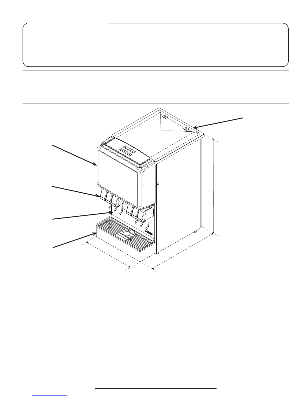
Blue Star IBD CB Series 22”
A
B
C
D
E
22.0 in.
DIMENSIONS
Width: 22.0 inches (559 mm)
Depth: 30.5 inches (775 mm)
Height: 40.25 inches (1022 mm)
WEIGHT
Shipping: 310 lbs (141 kg)
Empty (without Ice): 280 lbs (127 kg)
Ice Capacity: 200 lbs (91 kg)
ELECTRICAL
115 VAC / 60 Hz / 3.6 Amps
PLAIN WATER SUPPLY
40.25 in.
A. Top Cover
30.5 in.
B. Merchandiser
C. Valves
D. Splash Plate
E. Drip Tray
CARBONATED WATER SUPPLY
Min Flowing Pressure: 25 PSI (0.172 MPA)
Max Static Pressure: 65 PSI (0.448 MPA)
CARBON DIOXIDE (CO2) SUPPLY
Min Pressure: 70 PSIG (0.483 MPA)
Max Pressure: 80 PSIG (0.552 MPA)
FITTINGS
Carbonator Inlet: 3/8 inch barb
Plain Water Inlet: 3/8 inch barb
Brand Syrup Inlets: 3/8 inch barb
CO2 Inlet: 3/8 inch barb
Min Flowing Pressure: 75 PSIG (0.516 MPA)
4
This unit emits a sound pressure level below 70 dB
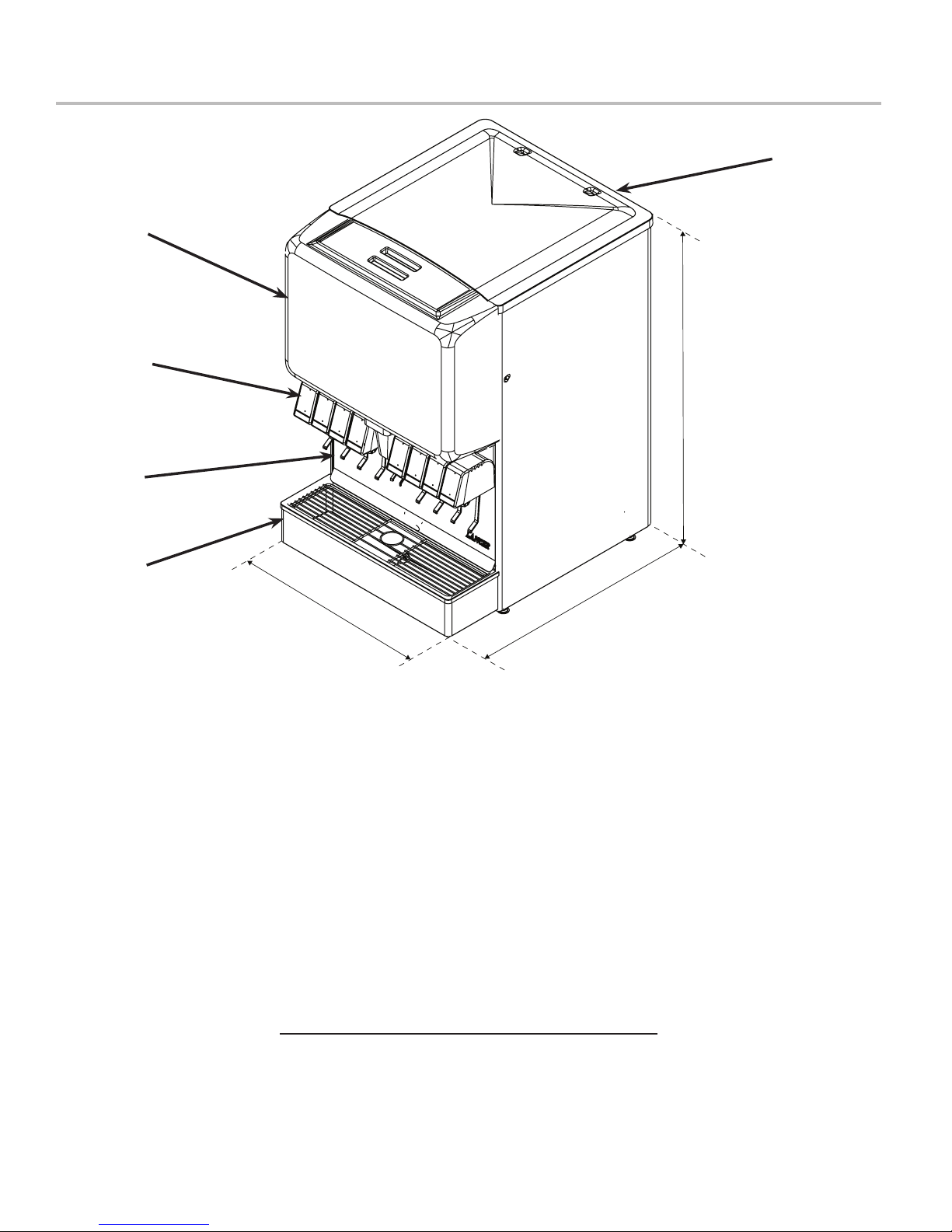
Blue Star IBD CB Series 25” & Renew IBD CB Series 25”
B
C
D
A
40.25 in.
E
25.0 in.
DIMENSIONS
Width: 25.0 inches (635 mm)
Depth: 30.5 inches (775 mm)
Height: 40.25 inches (1022 mm)
WEIGHT
Shipping: 331 lbs (150 kg)
Empty (without Ice): 295 lbs (134 kg)
Ice Capacity: 234 lbs (106 kg)
ELECTRICAL
115 VAC / 60 Hz / 3.6 Amps
PLAIN WATER SUPPLY
Min Flowing Pressure: 75 PSIG (0.516 MPA)
30.5 in.
A. Top Cover
B. Merchandiser
C. Valves
D. Splash Plate
E. Drip Tray
CARBONATED WATER SUPPLY
Min Flowing Pressure: 25 PSI (0.172 MPA)
Max Static Pressure: 65 PSI (0.448 MPA)
CARBON DIOXIDE (CO2) SUPPLY
Min Pressure: 70 PSIG (0.483 MPA)
Max Pressure: 80 PSIG (0.552 MPA)
FITTINGS
Carbonator Inlet: 3/8 inch barb
Plain Water Inlet: 3/8 inch barb
Brand Syrup Inlets: 3/8 inch barb
Flavor Shot Inlets: ““ inch barb
CO2 Inlet: 3/8 inch barb
This unit emits a sound pressure level below 70 dB
5
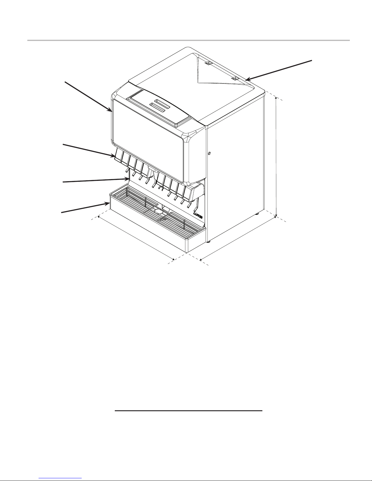
Blue Star IBD CB Series 30” & Renew IBD CB Series 30”
B
C
D
A
40.25 in.
E
30.0 in.
DIMENSIONS
Width: 30 inches (762 mm)
Depth: 30.5 inches (775 mm)
Height: 40.25 inches (1022 mm)
WEIGHT
Shipping: 365 lbs (161 kg)
Empty (without Ice): 320 lbs (145 kg)
Ice Capacity: 290 lbs (132 kg)
ELECTRICAL
115 VAC / 60 Hz / 3.6 Amps
PLAIN WATER SUPPLY
Min Flowing Pressure: 75 PSIG (0.516 MPA)
30.5 in.
A. Top Cover
B. Merchandiser
C. Valves
D. Splash Plate
E. Drip Tray
CARBONATED WATER SUPPLY
Min Flowing Pressure: 25 PSI (0.172 MPA)
Max Static Pressure: 65 PSI (0.448 MPA)
CARBON DIOXIDE (CO2) SUPPLY
Min Pressure: 70 PSIG (0.483 MPA)
Max Pressure: 80 PSIG (0.552 MPA)
FITTINGS
Carbonator Inlet: 3/8 inch barb
Plain Water Inlet: 3/8 inch barb
Brand Syrup Inlets: 3/8 inch barb
Flavor Shot Inlets: ““ inch barb
CO2 Inlet: 3/8 inch barb
This unit emits a sound pressure level below 70 dB
6
Features of the Blue Star IBD CB Series 22”/25”/30”
Cold Carbonation Capability
• Water is pre-chilled in the cold plate before entering the
carbonator tank.
• This allows it to absorb CO2 more eectively inside the
tank.
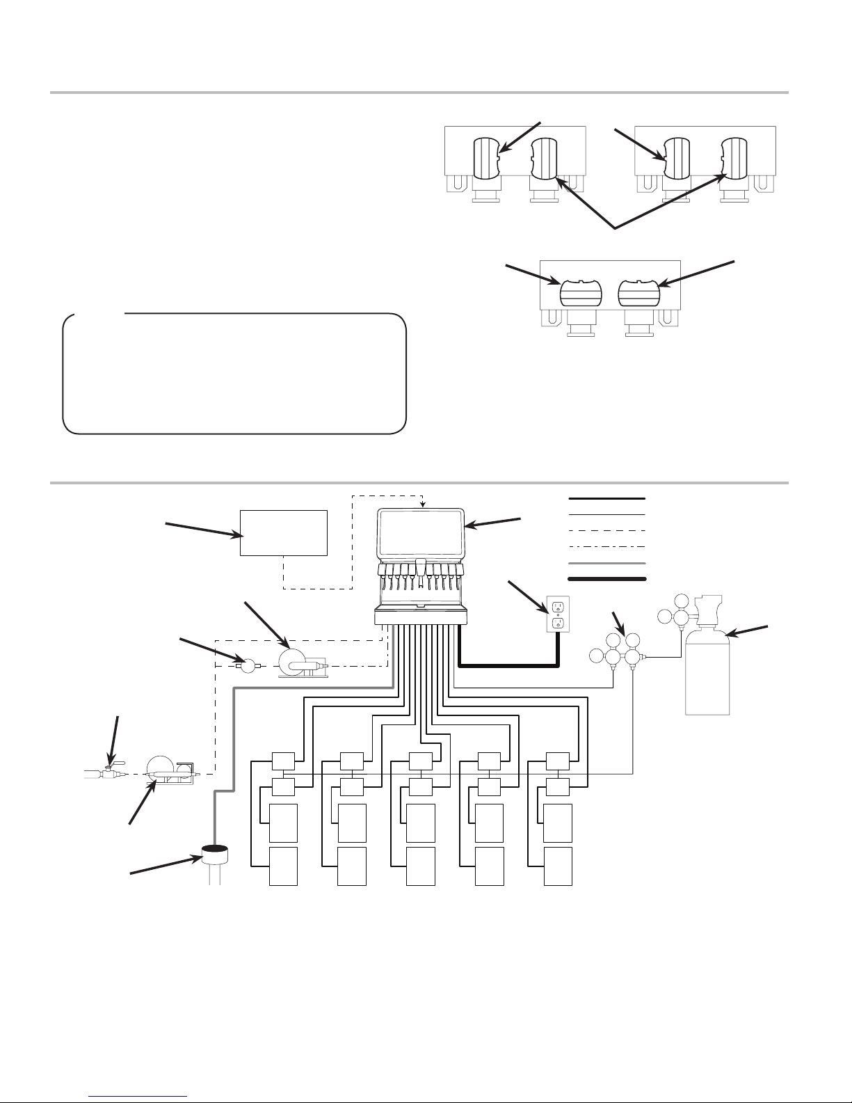
Three-Way Adjustable Back Blocks
• Allows for exibility between carbonated or plain water
drinks on the valves of your choice.
• To set adjustable back blocks, turn the shut-o stem to the
desired location, refer to the image below:
D
NOTE
Thereis100%exibilityonthe22”,6valveandthe30”
8 valve dispensers.
The30”,10valveandthe25”8valvedispensers
have space restrictions, so the two center valves are
plumbed only for carbonated watered drinks and are
non-adjustable.
General System Overview - Remote Syrup Pumps
I
E
D
A
H
J
B
C
E
A. Plain Water ON D. Water Closed
B. Carb Water ON E. Syrup Closed
C. Syrup ON
Syrup Line
CO2 Line
Plain Water Line
Carb Water Line
Drain Line
Electrical
K
110
L
75
75
A
F
F
B
C
G G G G G
G G G G G
A. Water Source
B. Water Booster
F
F
F F
F F
F
F
C. Floor Drain
D. Water Regulator
E. Remote Pump
F. Syrup Pump
G. BIB Syrup Containers
H. Dispenser
I. Icemaker (Optional)
J. Electrical Outlet
K. CO2 Regulator
L. CO2 Source
7
PRE-INSTALLATION CHECKLIST
TOOLS REQUIRED:
Oetiker Pliers
Tubing Cutters
Wrench
Slotted Screwdriver
Phillips Screwdriver
Drill
BIB SYSTEM:
BIB Rack
BIB Syrup Boxes
BIB Regulator Set
BIB Connectors
POST MIX ACCESSORIES:
High Pressure CO2 Regulator
Low Pressure CO2 Regulator
Manifold
CO2 Supply
Chain for CO2 Tank
Beverage Dispenser
Beverage Tubing
Oetiker Clamp Fittings
Water Booster (Lancer PN:
82-3401 or MC-163172
Water Regulator (supplied with
unit)
CONSIDER THE FOLLOWING
BEFORE INSTALLATION:
Location of Water Supply Lines
Location of Drain
Location of Electrical Outlet
Location of Heating and Air
Conditioning Ducts
Do you have enough space to
install the dispenser?
Is countertop level?
Can the countertop support the
weight of the dispenser? (Include
the weight of an ice machine plus
weight of ice, if necessary)
Is dispenser located away from
direct sunlight or overhead
lighting?
INSTALLATION
Read This Manual
This manual was developed by Lancer Corporation as a reference guide for the owner/operator and installer of this dispenser.
Please read this manual before installation and operation of this dispenser. See pages 20 - 23 for troubleshooting or service
assistance. If the service cannot be corrected please call your Service Agent or Lancer Customer Service. Always have your
model and serial number available when you call.
Unpacking the Dispenser
1. Set shipping carton upright on the oor then cut package
banding straps and remove.
2. Open top of carton and remove interior packaging.
3. Lift carton up and o of the unit.
4. Remove plywood shipping base from unit by moving unit so
that one side is o the counter top or table allowing access
to screws on the bottom of the plywood shipping base.
NOTE
If unit is to be transported, it is advisable to leave the
unit secured to the plywood shipping base.
5. Remove accessory kit and loose parts from ice
compartment.
NOTE
Inspect unit for concealed damage. If evident, notify
deliveringcarrierandleaclaimagainstthesame.
6. If leg kit has been provided, assemble legs by tilting unit.
! ATTENTION
DO NOT LAY UNIT ON ITS SIDE OR BACK
8
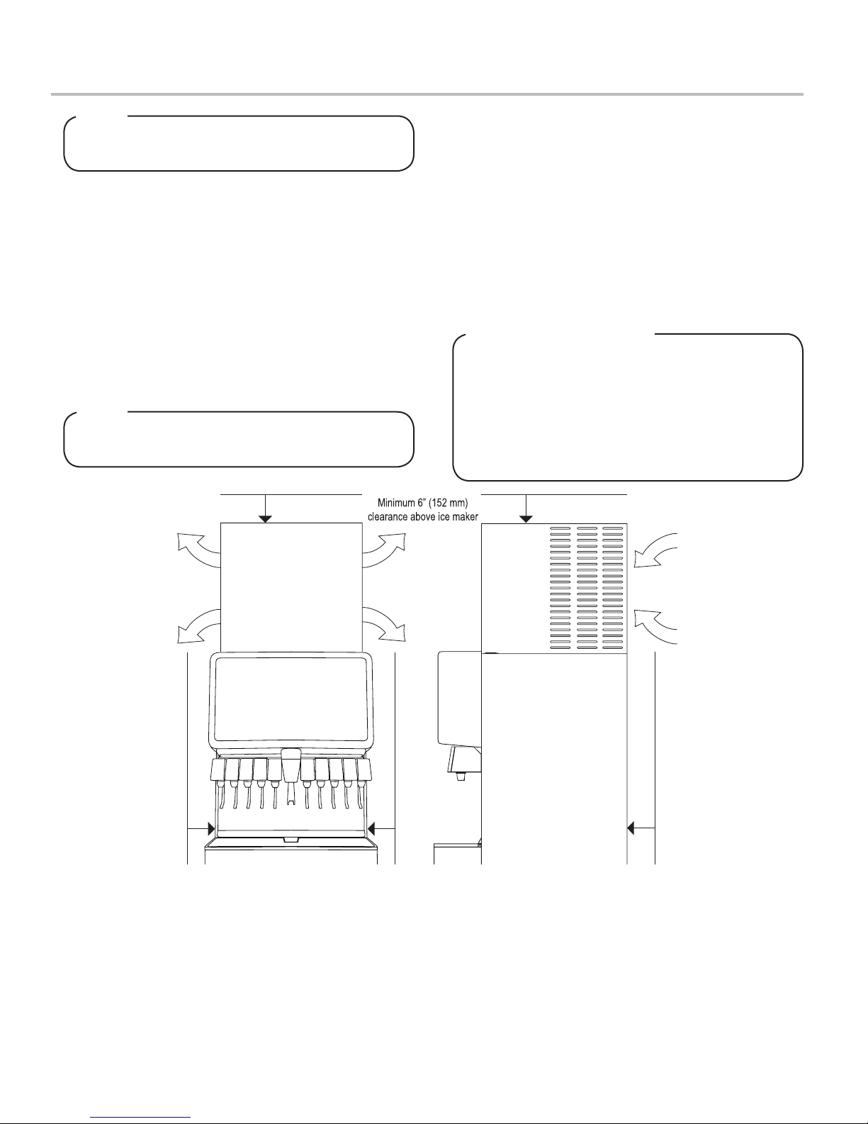
Selecting/Preparing a Counter Location
A
I
R
O
U
T
A
I
R
O
U
T
A
I
R
I
N
A
I
R
O
U
T
A
I
R
I
N
A
I
R
O
U
T
6” (152 mm) clearance
6” (152 mm) clearance
6” (152 mm) clearance
NOTE
The dispenser should only be installed in a location
where it can be overseen by trained personnel
1. Select a level, well ventilated location that is in close
proximity to a properly grounded electrical outlet, within ve
(5) feet (1.5 m) of a drain, a water supply that meets the
requirements shown in the Specications section found on
pages 4-6, away from direct sunlight or overhead lighting,
and has sucient clearance for air circulation.
2. Sucient clearance must be provided, if an ice maker is not
installed, to allow lling ice compartment from a ve gallon
bucket (a minimum of 16 inches is recommended).
3. The selected location should be able to support the weight
of the dispenser, ice and possibly an icemaker being
installed after counter cut out is made. Total weight (with
icemaker) for this unit could exceed 800 pounds (363.6kg).
NOTE
Lancer does NOT recommend the use of shaved or
akeiceinthedispenser.
4. Unit may be installed directly on countertop or on legs. If
installed directly on the counter, unit must be sealed to the
countertop with an FDA approved sealant. If an icemaker is
to be mounted on top of dispenser, do not install dispenser
on legs.
5. Select a location for the remote pump deck, remote syrup
pumps, remote avor shot syrup pumps (if necessary), CO2
t a n k , s y r u p c o n t a i n e r s , a n d w a t e r l t e r ( r e c o m m e n d e d ) .
Please see General System Overview on page 5 for
reference.
6. U s i n g C o u n t e r C u t o u t T e m p l a t e p r o v i d e d , c u t o u t r e q u i r e d
opening for the water, syrup, and CO2 lines in the
designated dispenser location.
Leveling the Dispenser:
In order to facilitate proper dispenser drainage,
ensure that the dispenser is level, front to back and
side to side. Place a level on the top of the rear edge
of the dispenser. The bubble must settle between the
level lines. Repeat this procedure for the remaining
three sides. Level unit if necessary. For optimum
performance place the unit at a 0° tilt. The maximum
tilt is 5°.
9
 Loading...