

Page 1
INSTALLATION AND SERVICE MANUAL
FOR
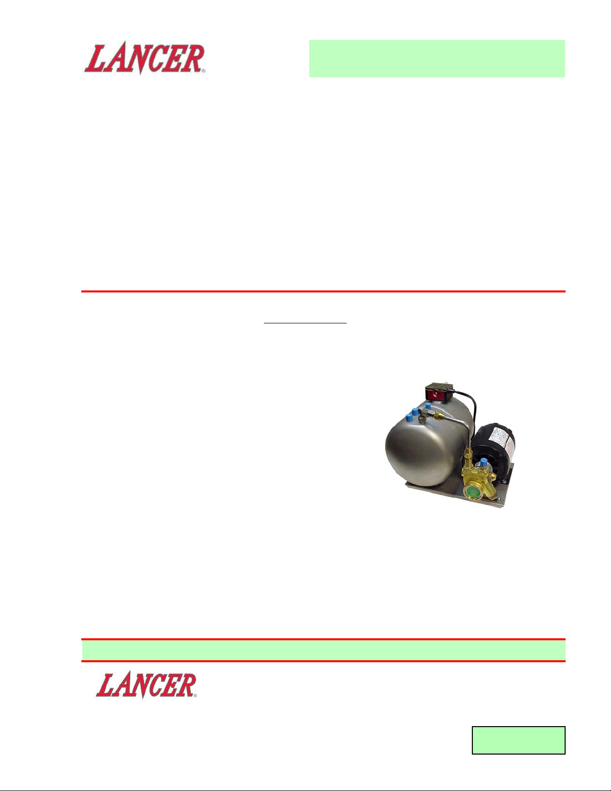
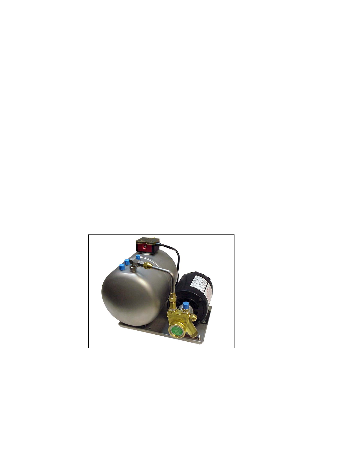
TURBO-CARB HIGH CAPACITY CARBONATOR
Part Number 85-2000, 115 Volts, 60 Hz
Part Number 85-2000-06, 115 Volts, 60 Hz
This Manual supersedes 28-0432, dated 05/05/00
"Lancer" is the registered trademark of Lancer • Copyright — 2000 by Lancer, all rights reserved.
FAX ENGINEERING: • 210-310-7096
SPECIFICATIONS
DIMENSIONS
Width 12 1/4 inches (31.11 cm)
Depth 15 1/4 inches (38.74 cm)
Height 11 1/2 inches (29.21 cm)
WEIGHT
Shipping 33.5 pounds (15.2 kg)
Empty 31.1 pounds (14.1 kg)
Operating 45.3 pounds (20.5 kg)
ELECTRICAL
Operating Voltage 115
Hertz 60
Amps 6.2
MOTOR 1/3 Horsepower (HP)
PUMP 125 Gallons Per Hour (GPH)
[473 Liters Per Hour (LPH)]
WATER INLET 3/8 inch S.A.E. Male Flare
CO
2 INLET 1/4 inch S.A.E. Male Flare
CARBONATED WATER OUTLET (TWO) 3/8 inch S.A.E. Male Flare
TANK OPERATING CAPACITY 215 Ounces (6.4 L)
DATE: 08/08/00
P.N. 28–0432/01
6655 LANCER BLVD. • SAN ANTONIO, TEXAS 78219 USA • (210) 310-7000
FAX SALES
• NORTH AMERICA – 210-310-7245 • INTERNATIONAL SALES – 210-310-7242 • CUSTOMER SERVICE – 210-310-7242 •
• LATIN AMERICA – 210-524-9567 / 210-310-7245 • EUROPE – 32-2-755-2399 • PACIFIC – 61-8-8268-1978 •
Please refer to the Lancer web site (www.lancercorp.com) for
information relating to Lancer Installation and Service Manuals,
Instruction Sheets, Technical Bulletins, Service Bulletins, etc.
Page 2
T
ABLE OF CONTENTS
SPECIFICATIONS
TABLE OF CONTENTS ......................................................................................................................................i
THEORY OF OPERATION..................................................................................................................................i
1. INSTALLATION ...........................................................................................................................................1
1.1 RECEIVING........................................................................................................................................1
1.2 SELECTING LOCATION ....................................................................................................................1
1.3 CONNECT WATER LINE TO PUMP..................................................................................................1
1.4 CONNECT CO
2 LINE TO TANK ........................................................................................................1
1.5 CONNECT CARBONATED WATER TO DISPENSING SYSTEM .....................................................1
1.6 ELECTRIC POWER SUPPLY ............................................................................................................1
2. START UP ...................................................................................................................................................2
2.1 START UP PROCEDURE ..................................................................................................................2
3. CLEANING AND REPLACEMENT .............................................................................................................2
3.1 CO2 CHECK VALVE...........................................................................................................................2
3.2 INLET WATER CHECK VALVE..........................................................................................................2
3.3 PUMP STRAINER SCREEN..............................................................................................................3
3.4 REPLACING LIQUID LEVEL CONTROL (LLC).................................................................................3
4. TROUBLESHOOTING.................................................................................................................................3
4.1 MOTOR FAILS TO START (MOTOR HUMS) ....................................................................................3
4.2 MOTOR FAILS TO START (MOTOR DOES NOT HUM)...................................................................3
4.3 MOTOR RUNS CONTINUOUSLY .....................................................................................................3
4.4 WATER IS RELEASED FROM PRESSURE RELIEF VALVE............................................................4
4.5 LOW CARBONATION ........................................................................................................................4
4.6 FOAMY PRODUCT............................................................................................................................4
5. ILLUSTRATIONS, PARTS LISTINGS, AND WIRING DIAGRAMS............................................................4
5.1 CO2 CHECK VALVE ASSEMBLY.......................................................................................................4
5.2 CHECK VALVE ASSEMBLY...............................................................................................................4
5.3 LARGE CARBONATOR TANK........................................................................................................4-5
5.4 PUMP ASSEMBLY .............................................................................................................................6
i
THEORY OF OPERATION
A carbonator is a device designed to dissolve carbon dioxide gas (CO2) in water, producing carbonated water.
CO2 gas is delivered through a regulator to the carbonator tank. Simultaneously, plain water is pumped into
the tank. The CO
2 gas, under pressure, dissolves in the water and the result is carbonated water. When the
level of carbonated water reaches a pre-determined point, the liquid level sensing device (inside the tank)
signals the liquid level control module which, in turn, shuts off the pump motor. As carbonated water is drawn
from the tank, the level of carbonated water will drop. At a certain point, the liquid level sensing device
recognizes that drop in the level and turns on the pump motor which replenishes the amount of carbonated
water that has been taken out of the tank.
Page 3

1. INSTALLATION
1.1 RECEIVING
A. Each unit is completely tested under operating conditions and thoroughly inspected before
shipment. At the time of shipment, the carrier accepts the unit and any claim for damage(s)
must be made with the carrier. Upon receiving units from the delivering carrier, carefully inspect
carton for visible indication(s) of damage. If damage exists, have carrier note same on bill of
lading and file a claim with the carrier.
B. Open the top of the carton. Remove interior packing. Carefully lift the Carbonator out of
carton.
C. Inspect for concealed damage(s) and if damages are detected, notify delivering carrier and file
claim.
1.2 SELECTING LOCATION
A. Select a level, well ventilated, accessible location convenient to water and electric supply. The
selected location should be able to withstand a load of 100 pounds (45.5 kg).
1.3 CONNECT WATER LINE TO PUMP
A. Connect Flexible Pressure Tubing, 3/8 inch ID or larger, from water supply to Pump Inlet using
a 3/8 inch SAE Female Swivel Nut (PN 01-0232) and Flare Seal Washer (PN 05-0017).
B. A Shutoff Valve should be installed in water line to Carbonator.
C. Water supply must provide a minimum flow rate of 125 GPH (473 LPH), and have a minimum
pressure of 25 PSIG (1.83 kg/cm
2
) and a maximum of 80 PSIG (5.62 kg/cm2). If water pressure
exceeds 80 PSIG (5.62 kg/cm
2
), install a Regulator (Lancer models are available) and adjust to
50 PSIG (3.51 kg/cm
2
).
D. Off tastes and excessive silt, sand, or iron require that a water filter be installed in the water
supplying the Carbonator. The water filter should be checked periodically, as required by local
conditions.
NOTE
Do not connect to a heated (hot) water source or a water source supplying soft water. This will
cause excessive foaming.
1.4 CONNECT CO
2 LINE TO TANK
A. Connect Flexible Pressure Tubing, 1/4 inch ID or larger from CO
2 Regulator to the Tank Inlet
using a 1/4 inch SAE Female Swivel Nut and Flare Seal Washer.
B. CO
2 supply must have a Regulator (Lancer models are available) and Gauge (Lancer models
are available) adjustable from 0 to 150 PSIG (3.5 kg/cm
2
) minimum.
1.5 CONNECT CARBONATED WATER TO DISPENSING SYSTEM
A. Connect Flexible Pressure Tubing, 3/8 inch ID or larger, from Dispensing System to Outlet on
Tank, using a 3/8 inch SAE Female Swivel Nut and Flare Seal Washer.
B. If only one Carbonated Water Outlet on the Tank is used, the other Outlet must be capped with
a Stainless Steel Cap Nut (PN 01-0212) and Flare Seal Washer (PN 05-0017).
1.6 ELECTRIC POWER SUPPLY
W
ARNING
THIS UNIT MUST BE PROPERLY ELECTRICALLY GROUNDED TO AVOID POSSIBLE FATAL
ELECTRICAL SHOCK OR SERIOUS INJURY TO THE OPERATOR. THE POWER CORD IS
PROVIDED WITH A THREE PRONG GROUNDED PLUG. IF A THREE HOLE GROUNDED
ELECTRICAL OUTLET IS NOT AVAILABLE, USE AN APPROVED METHOD TO GROUND THE
UNIT.
A. The electric power supply must be a three prong, ground convenience outlet having the same
configuration as the power cord.
B. Outlet must have proper voltage, cycles and ampere ratings. See Carbonator Name Plate for
ratings.
NOTE
Do not plug into electrical outlet unless ratings on name plate agree with local current available.
1
Page 4

2
2. START UP
2.1 START UP PROCEDURE
A. Turn water supply ON, and start filling Tank.
B. Pull UP on Pressure Relief Valve Yellow Lever to allow air to escape.
C. Hold Pressure Relief Valve OPEN, until Tank is full and water spurts out of Valve.
D. Check for water leaks.
E. Turn on CO
2 supply and set Regulator at 100 PSIG (7.03 kg/cm
2
).
F. Check for CO
2 leaks (see Section 3.1).
W
ARNING
THIS UNIT MUST BE PROPERLY ELECTRICALLY GROUNDED TO AVOID POSSIBLE FATAL
ELECTRICAL SHOCK OR SERIOUS INJURY TO THE OPERATOR. THE POWER CORD IS
PROVIDED WITH A THREE PRONG GROUNDED PLUG. IF A THREE HOLE GROUNDED
ELECTRICAL OUTLET IS NOT AVAILABLE, USE AN APPROVED METHOD TO GROUND THE
UNIT.
G. Plug in power supply.
H. Open a Dispensing Valve. Allow water to flow until Pump Motor turns on.
I. Close Dispensing Valve and allow Pump Motor to cycle off.
J. Repeat steps H and I several times, until carbonated water flows freely from Valve.
K. Check for leaks (see Section 3.2).
L. Check CO
2 Regulator to ensure that CO2 pressure has not changed.
3. CLEANING AND REPLACEMENT
3.1 CO
2
CHECK VALVE
A. UNPLUG Power Cord.
B. Shut water supply OFF to Pump.
C. Turn CO
2
supply OFF and set CO2 pressure regulator at 0 PSIG.
D. Disconnect CO
2 supply line from CO2 Check Valve.
CAUTION
DO NOT PROBE VALVE WITH ANY OBJECT.
E. Cover end of Check Valve with soap suds. If Check Valve is defective, gas bubbles will appear.
If a leak is detected, continue with the following steps.
F. Release pressure in Tank, using Relief Valve.
G. Disassemble Check Valve Body and components. Inspect Spring and O-Rings. Replace as
required.
H. Reassemble and reinstall Check Valve.
I. Reconnect CO
2 supply line to CO2 Check Valve.
J. Follow start up procedure (see Section 2.1) to put Carbonator back into operation.
3.2 INLET WATER CHECK VALVE
CAUTION
A LEAKING INLET WATER CHECK VALVE WILL ALLOW CARBONATED WATER TO FLOW BACK
THROUGH THE PUMP (WHEN IT IS SHUT OFF), AND CONTAMINATE THE WATER SUPPLY.
A. UNPLUG Power Cord.
B. Shut water supply OFF to Pump.
C. Set CO
2 pressure at 100 to 125 PSIG (7.0 to 8.8 kg/cm
2
).
D. Disconnect Stainless Steel Water Line from Water Inlet Check Valve. Do not loosen Check
Valve Assembly.
CAUTION
DO NOT PROBE VALVE WITH ANY OBJECT.
E. Cover end of Check Valve with soap suds. If Check Valve is defective, gas bubbles will appear.
If a leak is detected, continue with the following steps. If no leak is detected, proceed to
Step J below.
F. Turn CO
2 pressure OFF. Release pressure in Tank, using Relief Valve.
Page 5

G. Disassemble Check Valve Body and components. Inspect Spring and O-Rings. Replace as
required.
H. Reassemble and reinstall Check Valve.
I. Reconnect Stainless Steel Line to water inlet Check Valve.
J. Follow start up procedure (see Section 2.1) to put Carbonator back into operation.
3.3 PUMP STRAINER SCREEN
A. UNPLUG Power Cord.
B. Shut water supply OFF to Pump.
C. Unscrew Brass Plug on Pump, and remove Strainer from Pump.
D. Inspect and clean, or replace, Strainer Screen.
E. Reinstall Strainer, and tighten Brass Plug.
F. Turn water supply ON.
G. Check for leaks. If a leak is detected, carefully tighten Brass Plug.
W
ARNING
THIS UNIT MUST BE PROPERLY ELECTRICALLY GROUNDED TO AVOID POSSIBLE FATAL
ELECTRICAL SHOCK OR SERIOUS INJURY TO THE OPERATOR. THE POWER CORD IS
PROVIDED WITH A THREE PRONG GROUNDED PLUG. IF A THREE HOLE GROUNDED
ELECTRICAL OUTLET IS NOT AVAILABLE, USE AN APPROVED METHOD TO GROUND THE
UNIT.
H. Plug Power Cord into electrical outlet.
3.4 REPLACING LIQUID LEVEL CONTROL (LLC)
A. UNPLUG Power Cord.
B. Shut water and CO
2 gas supplies OFF.
C. Pull lever on Pressure Relief Valve to relieve CO2 pressure on Tank.
D. Remove three (3) screws securing existing LCC to top of Tank and remove LLC.
E. Install new LLC into top of Tank and secure with three (3) screws removed in previous step.
Ensure O-Ring (PN 02-0464) is properly installed to ensure a water tight seal is obtained.
F. Follow start-up procedure (see Section 2.1) for putting Carbonator back into operation.
4. TROUBLESHOOTING
TROUBLE
CAUSE REMEDY
4.1 Motor fails to start A. Pump binding. A. Loosen Pump CIamp and rotate
(Motor hums). Pump slightly to free binding, If this
fails, replace Pump.
B. Open Winding infield. B. Replace Motor.
4.2 Motor fails to start A. Cutout due to overloading A. Let Motor cool and follow Pump
(Motor does not hum). by Pump binding. binding remedy.
B. Blown Fuse, or Circuit B. Replace Fuse or reset Circuit
Breaker tripped. Breaker.
C. Defective Motor. C. Replace Motor.
D. Defective LLC. D. Replace LLC.
4.3 Motor runs continuously. A. Water supply shut off. A. Reestablish water supply.
B. Water supply pressure less B. Connect Pressure Gage to Pump
than 25 PSIG (1.86 kg/cm2). Tee and increase Pump By-Pass
pressure to 200 PSIG
(14.1 kg/cm2).
C. Restriction in Water C. Locate restriction and establish
Supply Line. proper flow.
D. Restriction in Inlet Water D. Disassemble Inlet Water Check
Check Valve. Valve and clean.
E. Restriction in Pump. E. Remove and clean Pump Strainer.
If Pump is still restricted, replace
Pump.
F. Defective LLC. F. Replace LLC.
(Troubleshooting continued next page)
3
Page 6

4.4 Water is released from A. Defective seal in Pressure A. Replace Pressure Relief Valve.
Pressure Relief Valve. Relief Valve.
B. Defective Spring in Pressure B. Replace Pressure Relief Valve.
Relief Valve.
4.5 Low Carbonation. A. Low CO
2 pressure. A. Increase CO2 pressure or
replace CO2 tank.
B. Leaking CO2 Supply Line. B. Locate leak and repair.
4.6 Foamy Product. A. Over carbonation. A. Reduce CO
2 pressure.
B. Dirty Product Valve. B. Disassemble and clean
Product Valve.
C. Product temperature C. Product temperature must be
too high. below 42
o
F (5.5oC). Check
cooling system.
4
TROUBLE
CAUSE REMEDY
ITEM
PART NO.
DESCRIPTION
1 07-0199/01 Base
2 82-2495 Uniprobe Assy (Liquid Level
Control)
3 11-0004 Connector
4 06-1134 Label, CO
2 Pressure
5 04-0247 Foot, Isolator
6 04-0034 Nut, Lock
7 04-0033 Washer
8 04-0520 Bolt, Hex, 1/4 - 20 x 1/2
9 04-0032 Nut, NYLOCK, 1/4 - 20
10 91-0008 Motor, 115 VAC
11 07-0017 Clamp
12 86-0085 Pump, Assy, REPL Bypass
13 01-0111 Adaptor
14A 48-1449 Tube Assy (For 85-2000)
R 14B 48-0507 Tube Assy (For 85-2000-06)
15 04-0045 Cap, Protector
16 04-0044 Cap, Protector
17 05-0017 Seal, Flare
5.3 LARGE CARBONATOR TANK
18 06-0003/02 Name Plate
19 06-0039 Label, WARNING
20 23-1176 Tank, Carbonator Assy
21 52-2159 Power Cord, Assy, 100”
22 52-2153 Power Cord, Carbonator,
Uniprobe
23 17-0342 Check Valve Assy, CO
2
24A 17-0083 Fitting Assy (For 85-2000)
24B 01-2013 Fitting Assy (For 85-2000-06)
25 54-0066 Relief Valve Assy
26A 17-0341 Check Valve Assy
(For 85-2000)
R 26B 17-0556 Vented Backflow Preventer
(For 85-2000-06)
R 27 01-1877 1/4 Barb
R 28 06-2251 Label, Check Valve
R 29 06-2014/01 Label, WARNING CO
2
R in margin indicates change or revision
ITEM
PART NO. DESCRIPTION
5. ILLUSTRATIONS, PARTS LISTINGS, AND WIRING DIAGRAMS
5.1 CO
2 CHECK VALVE ASSEMBLY
ITEM PART NO. DESCRIPTION
1 17-0342 CO2 Check Valve Assy
2 01-0669 Body
3 02-0025 O-Ring
4 01-0689 Sleeve
5 01-0674 Ball
6 03-0021 Spring
7 02-0003 O-Ring
5.2 CHECK VALVE ASSEMBLY
ITEM
PART NO. DESCRIPTION
1 17-0341 Check Valve Assy
2 01-0673 Body
3 02-0025 O-Ring
4 01-0689 Sleeve
5 01-0674 Ball
6 03-0021 Spring
7 02-0003 O-Ring
8 01-0670 Body
2 3
1
4
1
7
6
5
4
3
2
8
5
6
3
4
7
5
67
Page 7

5.3 LARGE CARBONATOR TANK (CONTINUED)
5
19
15
15
23
16
24A
25
24B
26A
17
28
17
27
29
26B
14A
17
14B
2
PN. 06-1835
LIGHT
ASSY 82-2495
PUMP MOTOR CONNECTION.
2. IF LIGHT BLINKS CHECK
CHECK POWER SUPPLY.
4
20
17
18
15
10
22
13
1
WARNING
21
6
3
6
100 GPH
M
A
D
E
I
N
I
T
A
Y
13
5
L
11
9
12
8
7
Page 8

5.4 PUMP ASSEMBLY
ITEM PART NO. DESCRIPTION
1 86-0085 Pump Assy
2 10-0175 Housing
- 10-0176 Housing, Stainless Steel
- 10-0395 Housing, Replaceable Bypass
3 54-0152 Bypass Seat Sub Assy
4 02-0115 O-Ring
5 17-0438 Bypass Valve Assy
- 17-0439 Bypass Valve Assy,
Stainless Steel
- 10-0396 Bypass Valve Assy,
Replaceable Bypass
6 81-0103 Bypass Valve Filter
7 03-0132 Spring Relief Valve
8 02-0192 Gasket, Acorn Nut
9 01-1771 Acorn Nut, Relief Valve
- 01-1198/01 Acorn Nut, Relief Valve,
Stainless Steel
10 10-0394 Relief Valve, Adjustment Screw
- 10-0183 Relief Valve, Adjustment Screw,
Stainless Steel
- 10-0397 Relief Valve, Adjustment Screw,
Replaceable Bypass
11 02-0181 O-Ring, Adjustment Screw
12 82-0415 Strainer
13 02-0185 O-Ring, Strainer Nut
14 01-1196/01 Cap Nut, Strainer
6
2
3
1
12
13
14
4
5
6
7
8
9
10
11
 Loading...