

Page 1
INSTALLATION AND SERVICE MANUAL
FOR
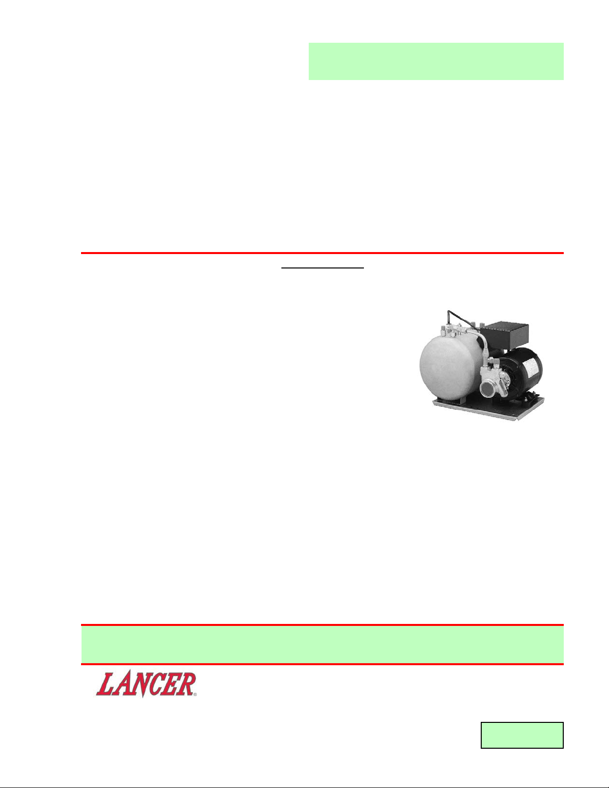
TURBO-CARB HIGH CAPACITY CARBONATOR
Part Number 85-1923, 115 Volts, 50/60 Hz
Part Number 85-1924, 230 Volts, 50/60 Hz
Part Number 85-1926, 115 Volts, 50/60 Hz, with Insulated Tank
Part Number 85-1965, 100 Volts, 50/60 Hz
This Manual supersedes Installation and Service Manual 28-0022/04, dated 11/22/99,
and is being published only on the Lancer Web Site.
SPECIFICA
TIONS
DIMENSIONS
Width 12 1/4 inches (31.11 cm)
Depth 15 1/4 inches (38.74 cm)
Height 11 1/2 inches (29.21 cm)
WEIGHT
Shipping 33.5 pounds (15.2 kg)
Empty 31.1 pounds (14.1 kg)
Operating 45.3 pounds (20.5 kg)
ELECTRICAL
Domestic Operating Voltage 115
Hertz 60
Amps 6.2
Export Operating Voltage 230
100 (Japan Only)
Hertz 50/60
Amps 3.5/3.0
MOTOR 1/3 Horsepower (HP)
PUMP 125 Gallons Per Hour (GPH)
[473 Liters Per Hour (LPH)]
WATER INLET 3/8 inch S.A.E. Male Flare
CO
2
INLET 1/4 inch S.A.E. Male Flare
CARBONATED WATER OUTLET (TWO) 3/8 inch S.A.E. Male Flare
TANK OPERATING CAPACITY 215 Ounces (6.4 L)
DATE: 09/26/01
P.N.: 28-0022/05
6655 LANCER BLVD. • SAN ANTONIO, TEXAS 78219 USA • (210) 310-7000
FAX SALES
• NORTH AMERICA – 210-310-7245 • INTERNATIONAL SALES – 210-310-7242 • CUSTOMER SERVICE – 210-310-7242 •
• LATIN AMERICA – 210-524-9567 / 210-310-7245 • EUROPE – 32-2-755-2399 • PACIFIC – 61-8-8268-1978 •
FAX ENGINEERING: • 210-310-7096
"Lancer" is the registered trademark of Lancer • Copyright — 2001 by Lancer, all rights reserved.
Please refer to the Lancer web site (www.lancercorp.com) for
information relating to Lancer Installation and Service Manuals,
Instruction Sheets, Technical Bulletins, Service Bulletins, etc.
Page 2

T
ABLE OF CONTENTS
SPECIFICATIONS
TABLE OF CONTENTS ......................................................................................................................................i
THEORY OF OPERATION..................................................................................................................................i
1. INSTALLATION ...........................................................................................................................................1
1.1 RECEIVING........................................................................................................................................1
1.2 SELECTING LOCATION ....................................................................................................................1
1.3 CONNECT WATER LINE TO PUMP..................................................................................................1
1.4 CONNECT CO
2 LINE TO TANK ........................................................................................................1
1.5 CONNECT CARBONATED WATER TO DISPENSING SYSTEM .....................................................1
1.6 ELECTRIC POWER SUPPLY ............................................................................................................1
2. START UP ...................................................................................................................................................2
2.1 START UP PROCEDURE ..................................................................................................................2
3. CLEANING AND REPLACEMENT .............................................................................................................2
3.1 INLET WATER CHECK VALVE..........................................................................................................2
3.2 CO2 CHECK VALVE...........................................................................................................................2
3.3 PUMP STRAINER SCREEN..............................................................................................................3
3.4 REPLACING PROBE .........................................................................................................................3
3.5 REPLACING P.C. BOARD .................................................................................................................3
4. TROUBLESHOOTING.................................................................................................................................4
4.1 MOTOR FAILS TO START (MOTOR HUMS) ....................................................................................4
4.2 MOTOR FAILS TO START (MOTOR DOES NOT HUM)...................................................................4
4.3 MOTOR RUNS CONTINUOUSLY .....................................................................................................4
4.4 WATER IS RELEASED FROM PRESSURE RELIEF VALVE............................................................4
4.5 LOW CARBONATION ........................................................................................................................4
4.6 FOAMY PRODUCT............................................................................................................................4
5. BASIC GO/NO GO CARBONATOR CONTROL TEST ..............................................................................5
6. ILLUSTRATIONS, PARTS LISTINGS, AND WIRING DIAGRAMS............................................................6
6.1 LARGE CARBONATOR TANK........................................................................................................6-7
6.2 CO2 CHECK VALVE ASSEMBLY.......................................................................................................7
6.3 CHECK VALVE ASSEMBLY...............................................................................................................7
6.4 PUMP ASSEMBLY .............................................................................................................................8
6.5 WIRING DIAGRAM (PN 06-0266/02) ................................................................................................8
THEORY OF OPERATION
A carbonator is a device designed to dissolve carbon dioxide gas (CO
2) in water, producing carbonated water.
CO
2 gas is delivered through a regulator to the carbonator tank. Simultaneously, plain water is pumped into
the tank. The CO2
gas, under pressure, dissolves in the water and the result is carbonated water. When the
level of carbonated water reaches a pre-determined point, the liquid level sensing device (inside the tank)
signals the liquid level control module which, in turn, shuts off the pump motor. As carbonated water is drawn
from the tank, the level of carbonated water will drop. At a certain point, the liquid level sensing device recognizes that drop in the level and turns on the pump motor which replenishes the amount of carbonated water
that has been taken out of the tank.
i
Page 3

1. INSTALLATION
1.1 RECEIVING
A. Each unit is completely tested under operating conditions and thoroughly inspected before
shipment. At time of shipment, the carrier accepts the unit and any claim for damage(s) must
be made with the carrier. Upon receiving units from the delivering carrier, carefully inspect
carton for visible indication(s) of damage. If damage exists, have carrier note same on bill of
lading and file a claim with the carrier.
B. Open the top of the carton. Remove interior packing. Carefully lift the Carbonator out ofcarton.
C. Inspect for concealed damage(s) and if detected, notify delivering carrier and file claim.
1.2 SELECTING LOCATION
A. Select a level, well ventilated, accessible location convenient to water and electric supply.
1.3 CONNECT WATER LINE TO PUMP
A. Connect Flexible Pressure Tubing, 3/8 inch ID or larger, from water supply to Pump Inlet using
a 3/8 inch SAE Female Swivel Nut and Flare Seal Washer.
B. A Shutoff Valve should be installed in water line to Carbonator.
C. Water supply must provide a minimum flow rate of 125 GPH (473 LPH), and have a minimum
pressure of 25 PSIG (1.83 kg/cm
2
) and a maximum of 80 PSIG (5.62 kg/cm2). If water pressure
exceeds 80 PSIG (5.62 kg/cm
2
), install a Regulator and adjust to 50 PSIG (3.51 kg/cm2).
D. Off tastes and/or excessive silt, sand, or iron require that a water filter be installed in the water
line supplying the Carbonator. The water filter should be checked periodically, as required by
local conditions.
NOTE
Do not connect to a heated (hot) water source or a water source supplying soft water. This will
cause excessive foaming.
1.4 CONNECT CO
2 LINE TO TANK
A. Connect Flexible Pressure Tubing, 1/4 inch ID or larger from CO2 Regulator to the Tank Inlet
using a 1/4 inch SAE Female Swivel Nut and Flare Seal Washer.
B. CO2 supply must have a Regulator and Gauge adjustable from 0 to 150 PSIG (3.5 kg/cm2)
minimum.
1.5 CONNECT CARBONATED WATER TO DISPENSING SYSTEM
A. Connect Flexible Pressure Tubing, 3/8 inch ID or larger, from Dispensing System to Outlet on
Tank, using a 3/8 inch SAE Female Swivel Nut and Flare Seal Washer.
B. If only one Carbonated Water Outlet on the Tank is used, the other Outlet must be capped with
a Stainless Steel Cap Nut and Flare Seal Washer.
1.6 ELECTRIC POWER SUPPLY
W
ARNING
THIS UNIT MUST BE PROPERLY ELECTRICALLY GROUNDED TO AVOID POSSIBLE FATAL
ELECTRICAL SHOCK OR SERIOUS INJURY TO THE OPERATOR. THE POWER CORD IS
PROVIDED WITH A THREE PRONG GROUNDED PLUG. IF A THREE HOLE GROUNDED
ELECTRICAL OUTLET IS NOT AVAILABLE, USE AN APPROVED METHOD TO GROUND THE
UNIT.
A. The electric power supply must be a three prong, ground convenience outlet having the same
configuration as the power cord.
B. Outlet must have proper voltage, cycles and ampere ratings. See Carbonator Name Plate for
ratings.
NOTE
Do not plug into electrical outlet unless ratings on name plate agree with local current available.
1
Page 4

2
2. START UP
2.1 START UP PROCEDURE
A. Turn water supply ON, and start filling Tank.
B. Pull UP on Pressure Relief Valve Ring to allow air to escape.
C. Hold Pressure Relief Valve OPEN, until Tank is full and water spurts out of Valve.
D. Check for water leaks.
W
ARNING
THIS UNIT MUST BE PROPERLY ELECTRICALLY GROUNDED TO AVOID POSSIBLE FATAL
ELECTRICAL SHOCK OR SERIOUS INJURY TO THE OPERATOR. THE POWER CORD IS
PROVIDED WITH A THREE PRONG GROUNDED PLUG. IF A THREE HOLE GROUNDED
ELECTRICAL OUTLET IS NOT AVAILABLE, USE AN APPROVED METHOD TO GROUND THE
UNIT.
E. Plug in power supply.
F. Turn on CO2 supply and set Regulator at 100 PSIG (7.03 kg/cm
2
).
G. Check for CO2 leaks (see Section 3.1).
H. Open a Dispensing Valve. Allow water to flow until Pump Motor turns on.
I. Close Dispensing Valve and allow Pump Motor to cycle off.
J. Repeat steps H and I several times, until carbonated water flows freely from Valve.
K. Check for leaks.
L. Check CO
2 Regulator to ensure that CO2 pressure has not changed.
3. CLEANING AND REPLACEMENT
3.1 INLET WATER CHECK VALVE
CAUTION
A LEAKING INLET WATER CHECK VALVE WILL ALLOW CARBONATED WATER TO FLOW BACK
THROUGH THE PUMP (WHEN IT IS SHUT OFF), AND CONTAMINATE THE WATER SUPPLY.
A. UNPLUG Power Cord.
B. Shut water supply OFF to Pump.
C. Set CO
2 pressure at 100 to 125 PSIG (7.0 to 8.8 kg/cm
2
).
D. Disconnect Stainless Steel Water Line from Water Inlet Check Valve. Do not loosen Check
Valve Assembly.
CAUTION
DO NOT PROBE CHECK VALVE WITH ANY OBJECT.
E. Cover end of Check Valve with soap suds. If Check Valve is defective, gas bubbles will appear.
If a leak is detected, continue with the following steps. If no leak is detected, proceed to Step J
below.
F. Turn CO2 pressure OFF. Release pressure in Tank, using Relief Valve.
G. Disassemble Check Valve Body and components. Inspect Spring and O-Rings. Replace as
required.
H. Reassemble and reinstall Check Valve.
I. Reconnect Stainless Steel Line to water inlet Check Valve.
J. Follow start up procedure (see Section 2.1) to put Carbonator back into operation.
3.2 CO
2
CHECK VALVE
A. UNPLUG Power Cord.
B. Shut water supply OFF to Pump.
C. Turn CO2 supply OFF and set CO2 pressure regulator at 0 PSIG.
D. Disconnect CO2 supply line from CO2 Check Valve.
CAUTION
DO NOT PROBE CHECK VALVE WITH ANY OBJECT.
E. Cover end of Check Valve with soap suds. If Check Valve is defective, gas bubbles will appear.
If a leak is detected, continue with the following steps.
Page 5

F. Release pressure in Tank, using Relief Valve.
G. Disassemble Check Valve Body and components. Inspect Spring and O-Rings. Replace as
required.
H. Reassemble and reinstall Check Valve.
I. Reconnect CO2 supply line to CO2 Check Valve.
J. Follow start up procedure (see Section 2.1) to put Carbonator back into operation.
3.3 PUMP STRAINER SCREEN
A. UNPLUG Power Cord.
B. Shut water supply OFF to Pump.
C. Unscrew Brass Plug on Pump, and remove Strainer from Pump.
D. Inspect and clean, or replace, Strainer Screen.
E. Reinstall Strainer, and tighten Brass Plug.
F. Turn water supply ON.
G. Check for leaks. If a leak is detected, carefully tighten Brass Plug.
W
ARNING
THIS UNIT MUST BE PROPERLY ELECTRICALLY GROUNDED TO AVOID POSSIBLE FATAL
ELECTRICAL SHOCK OR SERIOUS INJURY TO THE OPERATOR. THE POWER CORD IS
PROVIDED WITH A THREE PRONG GROUNDED PLUG. IF A THREE HOLE GROUNDED
ELECTRICAL OUTLET IS NOT AVAILABLE, USE AN APPROVED METHOD TO GROUND THE
UNIT.
H. Plug Power Cord into electrical outlet.
3.4 REPLACING PROBE
A. UNPLUG Power Cord.
B. Shut water and CO
2 gas supplies OFF.
C. Remove Cover from PC Board enclosure.
D. Unplug Probe Leads from PC Board.
E. Pull ring on Pressure Relief Valve to relieve CO
2 pressure on Tank.
F. Unscrew Probe from top of Tank.
G. Screw new Probe into top of Tank. Be sure to install White Plastic Washer as a water tight seal
seal will not be obtained without the washer.
H. Connect Probe Leads to PC Board as follows:
Green G
Black LO
White HI
I. Slide Probe Strain Relief into slot, replace cover and secure cover with screws.
J. Follow start-up procedure (see Section 2.1) for putting Carbonator back into operation.
3.5 REPLACING PC BOARD
A. UNPLUG Power Cord.
B. Carefully remove Cover from PC Board enclosure.
C. Unplug Probe Leads, Power Cord Leads, and Motor Cord Leads from PC Board.
D. Unscrew and remove PC Board Assembly.
E. Install new PC Board and secure with screws.
F. Connect push on Leads to PC Board as follows.
1. Probe
2. Power Cord 3. Motor Cord
Green G Black 1 Black 3
Black LO White 2 White 4
White HI
G. Install cover. Secure cover with two (2) screws.
H. Plug Power Cord IN.
3
Page 6

4. TROUBLESHOOTING
TROUBLE CAUSE REMEDY
4.1 Motor fails to start A. Pump binding. A. Loosen Pump CIamp and rotate
(Motor hums). Pump slightly to free binding, If this
fails, replace Pump.
B. Open Winding infield. B. Replace Motor.
4.2 Motor fails to start A. Cutout due to overloading A. Let Motor cool and follow Pump
(Motor does not hum). by Pump binding. binding remedy.
B. Blown Fuse, or Circuit B. Replace Fuse or reset Circuit
Breaker tripped. Breaker.
C. Defective Motor. C. Replace Motor.
D. Defective PC Board. D. Replace PC Board.
E. Defective Probe. E. Replace Probe.
4.3 Motor runs continuously. A. Water supply shut off. A. Reestablish water supply.
B. Water supply pressure less B. Connect Pressure Gage to Pump
than 25 PSIG (1.86 kg/cm2). Tee and increase Pump By-Pass
pressure to 200 PSIG
(14.1 kg/cm2).
C. Restriction in Water C. Locate restriction and establish
Supply Line. proper flow.
D. Restriction in Inlet Water D. Disassemble Inlet Water Check
Check Valve. Valve and clean.
E. Restriction in Pump. E. Remove and clean Pump Strainer.
If Pump is still restricted, replace
Pump.
F. Defective PC Board. F. Replace PC Board.
G. Defective Probe. G. Replace Probe.
4.4 Pressure Relief Valve A. Defective seal in Pressure A. Replace Pressure Relief Valve.
releases water. Relief Valve.
B. Defective Spring in Pressure B. Replace Pressure Relief Valve.
Relief Valve.
4.5 Low Carbonation. A. Low CO
2 pressure. A. Increase CO2 pressure or
replace CO2 tank.
B. Leaking CO2 Supply Line. B. Locate leak and repair.
4.6 Foamy Product. A. Over carbonation. A. Reduce CO
2 pressure.
B. Dirty Product Valve. B. Disassemble and clean
Product Valve.
C. Product temperature C. Product temperature must be
too high. below 42oF (5.5oC). Check
cooling system.
4
Page 7

5. BASIC GO/NO GO CARBONATOR CONTROL TEST
This is a test to determine if the liquid level control is operating properly. The test will simulate the rising
and falling of the water level in the tank. The test assumes the motor is known to be good.
5
1. Unplug Unit from AC power line.
2. Remove cover from control box.
WARNING
115 OR 220 VAC IS PRESENT ON TERMINALS 1, 2, 3,
AND 4.
3. Remove the 3 wire probe cable connectors from the G,
LO and HI terminals on the control board.
4. Plug the Unit into the AC power line. If the motor fails to
run, the control board is bad. If motor does run, go to
step 5.
NOTE
The carbonator motor should start running when plugged
in with no probe wires attached to the control board.
5. Connect clips to the G and to LO terminals. The motor
should continue to run. If the motor does not continue to
run, the board is bad. If motor runs, go to step 6.
6. Connect the remaining clip to the Hl terminal. The motor
should stop. If the motor does not stop, the board is bad.
If motor stops, go to step 7.
NOTE
The carbonator motor should stop running as soon as
the HI terminal is touched.
7. Remove clip from HI terminal and the motor should stay
OFF. lf the motor starts, the board is bad. If motor does
not run, go to step 8.
8. Remove clip from LO terminal and the motor should start
running. If the motor does not run, the board is bad. If
motor runs, go to step 9.
W
ARNING
UNPLUG UNIT.
9. To reconnect the 3 probe cable connectors, remember
white wire to
HI, black to.LO, green to G.
NOTE: THIS SAME TEST SEQUENCE MAY BE
USED WITH THE PROBE CONNECTED
TO THE ELECTRONIC CONTROL AND
USE THE ALLIGATOR JUMPER
CONNECTED TO THE APPROPRIATE
PROBE WIRE.
Page 8

6. ILLUSTRATIONS, PARTS LISTINGS, AND WIRING DIAGRAMS
6.1 LARGE CARBONATOR TANK
6
1
2
3
4
5
6
7
8
9
10
11
11
12
13
14
15
15
16
17
18
19
17
20
21
22
23
24
25
26
27
28
29
30
31
31
32
34
33
32
35
36
Turbo-Carb High Capacity Carbonator
Part Number 85-1923, 115 Volts, 50/60 Hz
Part Number 85-1924, 230 Volts, 50/60 Hz, Export
Part Number 85-1926, 115 Volts, 50/60 Hz, Insulated Tank
Part Number 85-1965, 100 Volts, 50/60 Hz
Page 9

7
6.1 LARGE CARBONATOR TANK (CONTINUED)
ITEM P
ART NO. DESCRIPTION
6.2 CO
2 CHECK VALVE ASSEMBLY
ITEM P
ART NO. DESCRIPTION
1 17-0342 CO2 Check Valve Assy
2 01-0669 Body
3 02-0025 O-Ring
4 01-0689 Sleeve
5 01-0674 Ball
6 03-0021 Spring
7 02-0003 O-Ring
ITEM PART NO. DESCRIPTION
6.3 CHECK VALVE ASSEMBLY
ITEM PART NO. DESCRIPTION
1 17-0341 Check Valve Assy
2 01-0673 Body
3 02-0025 O-Ring
4 01-0689 Sleeve
5 01-0674 Ball
6 03-0021 Spring
7 02-0003 O-Ring
8 01-0670 Body
ITEM PART NO. DESCRIPTION
ITEM P
ART NO. DESCRIPTION
1 07-0199/01 Base Plate
2 23-0369 Tank Assy
- 42-0015 Tank Assy, Insulated
3 06-0039 Label, Warning
4 17-0342 CO
2 Check Valve Assy
5 04-0044 Protector Cap
6 02-0096 Washer
7 54-0066 Relief Valve Assy
8 17-0083 Fitting Assy
9 17-0341 Check Valve Assy
10 04-0049 Nut
11 04-0297 Keps Nut
12 48-1449 Tube Assy, Insulated
- 48-1469 Tube Assy, Non-Insulated
13 05-0017 Flare Seal
14 52-0590/01 Probe
15 04-0045 Protector Cap
16 05-0528 Cover, Control
17 04-0470 Screw
18 13-0026 Strain Relief
19 06-0266/02 Label, Wiring Diagram
20 52-1017 PC Board, 115 Volt
- 52-1018 PC Board, 230 Volt
21 13-0028 Strain Relief
22 52-0588 Power Cord Assy
23 13-0008 Strain Relief
24 52-0585 Motor Cord Assy
25 05-0529 Enclosure Control
26 91-0008 Motor, 115V/50-60Hz
- 91-0011 Motor, 230V/50-60Hz
- 91-0132 Motor, 100V/50-60Hz (Japan)
27 04-0033 Washer
28 04-0520 Hex Bolt, 1/4 - 20 x 1/2 Inch
29 07-0017 Clamp
30 86-0085 Pump
31 01-0111 Adapter
32 04-0247 Isolator Foot
33 04-0032 Nut, 1/4 - 20, Nylock
34 04-0034 Lock Nut
35 11-0004 Connector
36 06-0003/02 Name Plate
2 3
4
2
3
4
5
6
7
1
5
6
7
8
3
4
5
67
Page 10

6.4 PUMP ASSEMBLY
6.5 WIRING DIAGRAM (PN 06-0266/02)
8
ITEM PART NO.
DESCRIPTION
1 86-0085 Pump Assy
2 10-0175 Housing
- 10-0176 Housing, Stainless Steel
- 10-0395 Housing, Replaceable Bypass
3 54-0152 Bypass Seat Sub Assy
4 02-0115 O-Ring
ITEM PART NO. DESCRIPTION
5 17-0438 Bypass Valve Assy
- 17-0439 Bypass Valve Assy,
Stainless Steel
- 10-0396 Bypass Valve Assy,
Replaceable Bypass
6 81-0103 Bypass Valve Filter
7 03-0132 Spring Relief Valve
8 02-0192 Gasket, Acorn Nut
9 01-1771 Acorn Nut, Relief Valve
- 01-1198/01 Acorn Nut, Relief Valve,
Stainless Steel
10 10-0394 Relief Valve, Adjustment Screw
- 10-0183 Relief Valve, Adjustment Screw,
Stainless Steel
- 10-0397 Relief Valve, Adjustment Screw,
Replaceable Bypass
11 02-0181 O-Ring, Adjustment Screw
12 82-0415 Strainer
13 02-0185 O-Ring, Strainer Nut
14 01-1196/01 Cap Nut, Strainer
2
1
12
3
4
5
6
7
8
13
14
J3
PROBE
LOW VOLTAGE
WHITE
BLACK
GREEN
HI LO
PC BOARD
G
9
10
11
GREEN
BLACK
WHITE
J4
L2
L1
MOTOR
115V or 230V*
WHITE
BLACK
GREEN
*100V FOR PN 85-1965
Page 11

(Continued from previous page)
EcuaLancer S.A. - Ecuador
Lancer Sales Company
Contact: Luciano Lopez
Sector Las Acacias
Luis De Beethoven #958
Y Capitan Rafael Ramos
Quito, Ecuador
Phone: 593-22-401-598, 400-937, 406-418
FAX: 593-22-400-535
e-mail: Llopez@ecnet.ec
Lancer Authorized Distributors
Eximport & Barter Co. - Caribbean
2101 S.W. 56th Terrace
Hollywood, FL 33023 USA
Phone: (954) 967-9999
FAX: (954) 967-9900
e-mail: edbrandao@aol.com
PromoVen, S.A. - Argentina
Contact: Rafael Mendoza
Juncal 858 - Piso 3 Depto. “L”
(1062) Buenos Aires
Argentina
Phone: (54.11)4394.7654
FAX: (54.11)4394.1193
e-mail: promoven@customw.com.ar
Bras Sulamericana LTDA. - Brasil
Contact: Fabio Queiroz
Rua. Dr. Ladislau Retti, 1400
Parque Alexandre
Cotia Sao Paulo - Brasil
CEP: 06714-150
Phone: 55-11-4612-1122
FAX: 55-11-4612-2219
e-mail: fabio.queiroz@bras.com.br
Lancer Chile Ltda. - Chile
Contact: Heriberto Concha
Vicuna Mackenna 3019, San Joaquin
Santiago, Chile
Phone: 56-2-552-1657
FAX: 56-2-552-1961
e-mail: hconcha@lancer-intl.com
Lancer Pacific
International Sales
6655 Lancer Blvd.
San Antonio, TX 78219
Phone: (210) 310-7000
FAX: (210) 310-7242
1-800-729-1500
e-mail: asia@lancercorp.com
Australia
Lancer Pacific Pty Ltd
5 Toogood Avenue
Beverley SA 5009
Australia
Phone: 61-8-8268-1388
FAX: 61-8-8268-1978
e-mail: ian-lunniss@lancer-pacific.com.au
steve-sotiriou@lancer-pacific.com.au
Lancer Pacific Pty Ltd
7 Slough Avenue
Silverwater, NSW, 2128
Sydney, Australia
Phone: 61-2-9648-6840
FAX: 61-2-9648-6850
e-mail: richard-abraham@lancer-
pacific.com.au
fiore-alvaro@lancer-pacific.com.au
(for Beer)
rob-burdock@lancer-pacific.com.au
(Senior Director - Asia)
Lancer Pacific Pty Ltd
55 Keele Street
Collingwood
Melbourne Victoria 3066
Australia
Phone: 03 8415 1920
FAX: 03 8415 1929
e-mail: glenn-blakiston@lancer-pacific.com.au
Lancer Pacific Pty Ltd
Unit 31, 284 Musgrave Drive
Coopers Plains 4108
Queensland
Australia
Phone: 61-7-3274-5700
FAX: 61-7-3875-1805
e-mail: brett-thomson@lancer-pacific.com.au
New Zealand
Lancer Pacific Ltd
9 O’Rorke Street
Onehunga, Auckland
New Zealand
Phone: 64-9-634-3612
FAX: 64-9-634-1472
e-mail: phil-mason@lancer-pacific.com.au
Hong Kong
Patrick Co - Area Manager - Asia
Phone: 852-29670900
FAX: 852-30105882
e-mail: patrickco@lancer-asia.com
Lancer Authorized Distributors
Shanghai Freser International Co Ltd. China
1856, Hu Tai Road
Shanghai, 200436, China
Phone: 86-21-5650-3555
FAX: 86-21-5650-2666
e-mail: daniel@freser.com.cn
Freser (HK) Company Ltd - Hong Kong
Flat A, 24/F., Houston Industrial Bldg.
32-40 Wang Lung Street
Tsuen Wan, N. T., Hong Kong
Phone: 852-2408-2595
FAX: 852-2408-2605
e-mail: freserhk@netvigator.com
P.T. Ciptapratama Sentosamakmur Indonesia
JI. Anggrek Nelly Murni, Blok A - 39, Slipi
Jakarta 11480, Indonesia
Phone: 62-21-532-3737
FAX: 62-21-532-3666
e-mail: ciptasm@indosat.net.id
Hayakawa Sanki - Japan
Hayakawa Sanki, Inc.
1-13-13, Kayaba-cho
Nihonbashi, Chuo-ku
Tokyo, 103-0025
Japan
Phone: 03-5651-1481
FAX: 03-5651-1445
e-mail: SANKI10217@aol.com
Tahoe Corporation - Korea
Tahoe Corporation
2FL, 835-66 Yocksam-dong
Kangnam-Ku
Seoul, Korea
Phone: 82-2-557-5612, -5614
FAX: 82-2-557-5615
e-mail: tahoepark@netsgo.com
Freser (MALAYSIA) SDN. BHD. - Malaysia
No. 31, Jalan TPP 5/13, Taman
Perindustrian Puchong, Seksyen 5,
47100 Puchong, Selangor, Malaysia
Phone: 60-3-8061-6666
FAX: 60-3-8062-1007
e-mail: freser@tm.net.my
R.B.P. Industrial Sales Inc - Philippines
Unit 20, Facilities Centre Bldg.
548 Shaw Blvd
Mandaluyong City, Philippines
Phone: 632-531-1215/1221/1289
FAX: 632-531-1271
e-mail: rbpsales@info.com.ph
Freser (S) Pte Ltd - Singapore
Blk 998 Toa Payoh North
#04-12/14
Singapore 318993
Phone: 65-6352-0943
FAX: 65-6352-8594
e-mail: fresersin@pacific.net.sg
Freser International Corporation - Taiwan
No. 76, Gui-Sui Street
Taipei 103, Taiwan R.O.C.
Phone: 886-2-2553-1555
FAX: 886-2-2553-2742
e-mail: allen@intl.freser.com.tw
Freser (Thailand) Co Ltd - Thailand
3/15 Moo 3, Soi Ruammitr
Tivanont Road, Banmai
Pakkred, Nonthaburi, 11120
Thailand
Phone: 662-961-9543
FAX: 662-961-9550
e-mail: prachat@asianet.co.th
Lancer - Indian Sub-Continent
India
Shabbir Shafiqui - Area Manager
India and Sub-Continent
B-7, Pannalal Silk Mill Compounds
78, LBS Marg, Bhandup (W)
Mumbai 400-078, India
Phone: 91-22-2561-6665
Cel No.: 91-98-2029-5252
FAX: 91-22-5637-4018
e-mail: shafiquis@vsnl.com
Lancer Authorized Distributors
Western Refrigeration Ltd - India
B-7, Pannalal Silk Mill Compounds
78 L.B.S. Marg, Bhandup (W)
Mumbai 400-078, India
Phone: 91-22-2561-6665
FAX: 91-22-2562-2257
e-mail: western@bom5.vsnl.net.in
Bengal Marketing Company - Bangladesh
Skylark Point (6th Floor)
Room #G-2
24/A Bijoy Nagar,
Dhaka-1000, Bangladesh
Phone: 880-2-934-2987
FAX: 880-2-935-0127
e-mail: bmc@dhaka.agni.com
Dynamic Equipment - Pakistan
Dynamic Equipment and Controls (Pvt.) Ltd.
F-1/23, Canal Cottages, Block-D.
New Muslim Town.
Lahore. Pakistan.
Phone: 0092-42-583-6737
0092-42-583-6787
FAX: 0092-42-586-7924
e-mail: info@dynamic-eqpt.com.pk
Directory of USA - Canada Offices,
International Offices, and Authorized Distributors
(Continued)
9
Page 12

Lancer USA
Manufacturing Locations
Foster Road Facilities
6655 Lancer Blvd
San Antonio, TX 78219
Phone: (210) 310-7000
MFG FAX: (210) 310-7088
ENG FAX: (210) 310-7096
ACCT FAX: (210) 310-7091
PURCH FAX: (210) 310-7094
Lancer FBD
5620 Business Park
San Antonio, TX 78218
Phone: (210) 666-0544
FAX: (210) 666-2044
Lancer Ice Link
6655 Lancer Blvd
San Antonio, TX 78219
Phone: (210) 310-7174
FAX: (210) 310-7245
Remanufacturing
6655 Lancer Blvd
San Antonio, TX 78219
Phone: (210) 310-7356
FAX: (210) 310-7261
1-800-729-1550
Lancer North America
USA - Canada Sales
6655 Lancer Blvd.
San Antonio, TX 78219
Phone: (210) 310-7000
SALES FAX: (210) 310-7245
CUSTOMER SERVICE FAX: (210) 310-7250
1-800-729-1500
Georgia Office
1125 Northmeadow Parkway, Suite 116
Roswell, GA 30076
Phone: (770) 343-8828
FAX: (770) 475-8646
1-800-729-1750
Lancer Authorized Distributors
Advanced Beverage Solutions (ABS)
1425 South Wright Blvd.
Schaumburg, IL 60193
Phone: (847) 524-1707
(877) 814-2271
FAX: (847) 524-1710
www.absone.com
Bevco
6900 Camille Avenue
Oklahoma City, OK 73149
Phone: (405) 672-7770
FAX: (405) 672-7443
e-mail: info@bevcoinc.com
Joe Kirwan Company
119 White Oak Lane
Old Bridge, NJ 08857
Phone: (732) 679-1900
FAX: (732) 679-9236
e-mail: sales@jkirwan.com
L & M Beverage Equipment Co. Inc.
12510 Santa Fe Trail Drive
Lenexa, KS 66215
Phone: (913) 888-8988
FAX: (913) 888-9137
e-mail: L7mco@aol.com
(Update #43 - as of March 05, 2003)
Ernest F. Mariani Company
614 West 600 South
Salt Lake City, UT 84104
Phone: (801) 359-3744
FAX: (801) 531-9615
e-mail: febell@efmco.com, or
clay@efmco.com
Mark Powers & Company, Inc.
P.O. Box 72
1821 Henry Street
Guntersville, AL 35976
Phone: (256) 582-6620
FAX: (256) 582-8533
e-mail: sales@markpowers-and-company.com
Maurer Supply, Inc.
843 Rainier Avenue South
Seattle, WA 98144
Phone: (206) 323-8640
FAX: (206) 323-9286
e-mail: maurersupply@qwest.net
Simgo Ltd.
5122 Timberlea Blvd.
Mississauga, Ontario L4W 2S5
Canada
Phone: 905-602-5800
FAX: 905-602-5804
e-mail: simgo@simgo.com
Simgo (B.C.) Ltd.
16-8125 - 130th Street
Surrey, B.C. V3W 7X4
Canada
Phone: 604-590-4022
FAX: 604-590-1601
Lancer Europe
Belgium - European Central Office
Lancer Europe, S.A.
Mechelsesteenweg 592
B-1930 Zaventem
Belgium
Phone: 32-2-755-2390
FAX: 32-2-755-2399
e-mail: lancer.europe@glo.be
England
17 Bembridge Gardens
Ruislip, Middlesex
HA4 7ER, England
Phone: 44-1895672667
FAX: 44-1895637537
e-mail: court4lancer@msn.com
Hungary
H-2100 Gödöllõ
Isaszegi út 67
Hungary
Phone: 36-28-417-179
FAX: 36-28416-881
e-mail: bodolai@compuserve.com
Lancer Authorized Distributors
Complete Beverage Services, Ltd.
Republic of Ireland and Northern Ireland
Gortrush Industrial Estate
Omagh County Tyrone
Northern Ireland
Office: 44-1662 250 008
FAX: 44-1662-252-991
Intercom - Spain
Intercom
Avda. Concha Espina 8
28036 Madrid Spain
Phone: 34-91-564 6900
FAX: 34-91-564 3065
e-mail: jmorales@bevserv.com
Lancer Russia
Lancer Sales Company
Vyatskaya Street 27
Building 15, 4th Floor
125015 Moscow, Russia
Phone: 7-095-745-7108
FAX: 7-095-745-7109
Mobile Phone: 7-095-991-7778
7-095-139-0335
e-mail: lancer@online.ru
vdemkin@ktv.ru
Lancer Middle East / Africa
Elsayed Moniem - Technical Manager
Lancer Middle East/Africa
7 Mubarak Street
East Ain Shams 11311
Cairo, Egypt
Phone/FAX: 2-02-49-35-395
Mobile Phone (GSM): 2-010-500-4007
e-mail: elsayed_lancer@msn.com
Lancer Authorized Distributor
DispenseTech - South Africa
P.O. Box 17495
Sunward Park, 1470
South Africa
Phone: 27-11-397-7455
FAX: 27-11-397-7648
e-mail: david@dispensetech.co.za
Lancer Latin America
Latin America Sales
6655 Lancer Blvd.
San Antonio, TX 78219
Phone: (210) 310-7000
FAX: (210) 310-7245
1-800-729-1500
e-mail: latinamerica@lancercorp.com
Lancer de México, S.A. de C.V.
Contact: Gerardo Canales
Calle Lerdo De Tejada #544 PTE.
Col. Las Villas
San Nicolas De Los Garza, N.L.
Monterrey, N. L., México C.P. 66422
Phone: (52)-81-83-52-85-32
Phone: (52)-81-83-52-85-34
Phone: (52)-81-83-52-53-60
FAX: (52)-81-83-32-54-10
e-mail: direccion@lancer.com.mx
Lancer de México, S.A. de C.V.
Branch Office, Mexico City
Contact: Carlos Lopez
Lancer de Mexico S.A. de C.V.
Sucursal Mexico D.F.
Calle: Centeotl No. 112
Colonia: La Preciosa
Delegacion: Azcapotzalco
Mexico D.F. C.P. 02460
Phone: (52)-55-53-53-89-28
Phone: (52)-55-53-53-89-26
Phone: (52)-55-53-53-88-60
Phone: (52)-55-53-53-88-21
FAX: (52)-55-53-52-46-30
e-mail: lancer@prodigy.net.mx
Lancer de México, Branch Office, Cd.
Juarez
Contact: Yolanda Puga
Lancer de Mexico
Camino de la Lomas # 4380
Col. Partido Iglesias
Cd. Juarez, CHIH, C.P. 32617
México
Phone and FAX: 521-605-00-86
Phone: 521-605-00-87
e-mail: cdjuarez@lancer.com.mx
(Continued on reverse)
10
Directory of USA - Canada Offices,
International Offices, and Authorized Distributors
Corporate Office
6655 Lancer Blvd. • San Antonio, Texas 78219 • 210-310-7000 • 1-800-729-1500 • FAX 210-310-7250
 Loading...