

Page 1
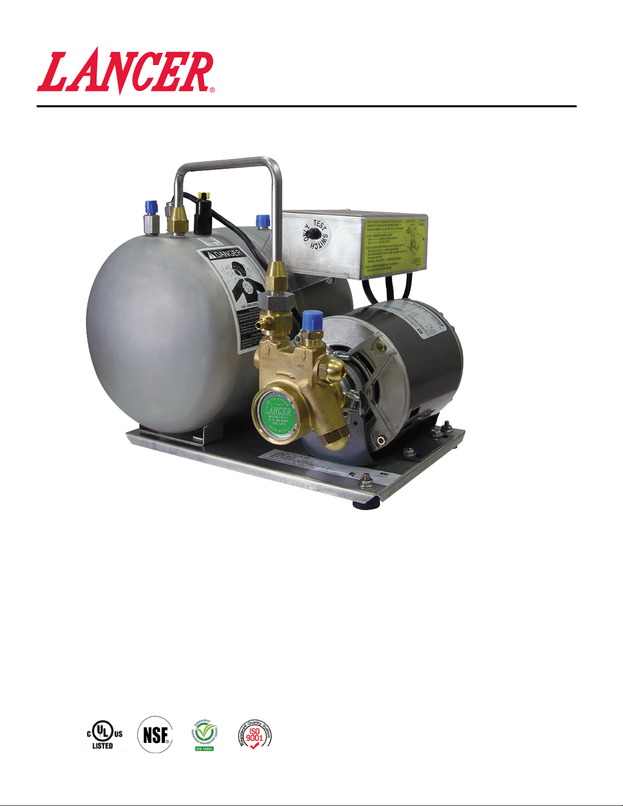
Turbo Carbonator
Operation Manual
PN: 28-0315/09
85-1923-00 Carbonator, 115V, VCV, Diagnostic
85-1923-01 Carbonator, 115V, VCV, Diagnostic, Insulated
85-1923-02 Carbonator, 115V, VCV, Diagnostic, Tee
85-1923-07 Carbonator, 115V, VCV, Diagnostic, Polished
85-1924-00 Carbonator, 230V, VCV, Diagnostic
85-1924-01 Carbonator, 230V, VCV, Diagnostic, Insulated
85-1924-06 Carbonator, 230V, VCV, Diagnostic, Reset
Certied
< 0.25 weighted
average percent lead
“Lancer” is the registered trademark of Lancer © 2014 by Lancer, all rights reserved.
Lancer Corp.
6655 Lancer Blvd.
San Antonio, Texas 78219
800-729-1500
Technical Support/Warranty: 800-729-1550
custserv@lancercorp.com
lancercorp.com
Manual PN: 28-0315/09
11/26/13
FOR QUALIFIED INSTALLER ONLY
Page 2
ABOUT THIS MANUAL
This booklet is an integral and essential part of the product and should be handed over to the operator after the
installation and preserved for any further consultation that may be necessary. Please read carefully the guidelines and
warnings contained herein as they are intended to provide the user with essential information for the continued safe
use and maintenance of the product. In addition, it provides GUIDANCE ONLY to the user on the correct services and
site location of the unit.
The installation and relocation, if necessary, of this product must be carried out by qualied personnel with up-to-date
safety and hygiene knowledge and practical experience, in accordance with current regulations.
TABLE OF CONTENTS
SPECIFICATIONS...............................................................................................................................................2
WARNINGS/CAUTIONS......................................................................................................................................3
THEORY OF OPERATION..................................................................................................................................4
1. INSTALLATION INSTRUCTIONS.................................................................................................................4
2. ELECTRICAL REQUIREMENTS..................................................................................................................4
2.1 IMPORTANT SAFETY INSTRUCTIONS.............................................................................................4
2.2 GROUNDING INSTRUCTIONS..........................................................................................................5
3. OPERATING INSTUCTIONS........................................................................................................................6
4. USER MAINTENANCE INSTRUCTIONS.....................................................................................................7
4.1 INSPECTIONS.....................................................................................................................................7
5. CLEANING AND REPLACEMENT...............................................................................................................7
5.1 CO2 CHECH VALVE...........................................................................................................................7
5.2 BACKFLOW PREVENTER.................................................................................................................7
5.3 PUMP STRAINER SCREEN...............................................................................................................7
5.4 REPLACING PROBE..........................................................................................................................8
5.5 REPLACING PC BOARD....................................................................................................................8
6. CONFIGURATION........................................................................................................................................9
7. TROUBLESHOOTING...........................................................................................................................10-11
8. ILUSTRATIONS, PARTS LISTINGS, AND WIRING DIAGRAMS..............................................................11
8.1 CHECK VALVE ASSEMBLY...............................................................................................................11
8.2 WIRING DIAGRAM............................................................................................................................11
8.3 CARBONATOR TANK.......................................................................................................................12
9. APPLIANCE DISPOSAL............................................................................................................................13
TURBO CARBONATOR SPECIFICATIONS
DIMENSIONS
Width: 12 1/4 inches (311 mm)
Depth: 15 1/4 inches (387 mm)
Height: 11 1/2 inches (292 mm)
ELECTRICAL
115 VAC / 60 Hz / 6.3 Amps
230 VAC / 56-60 Hz/ 3.5/3 Amps
TIMEOUT FEATURE: The carbonator is designed with a Timeout feature for self-protection. If the
carbonator runs for longer than three minutes without the demand for water being met, the carbonator will
shut down. On newer units, an automatic retry feature can be enabled to allow self-recovery within 3 hours.
Refer to Troubleshooting section.
WEIGHT
Shipping: 33.5 lbs (15.2 kg)
Empty: 31.1 lbs (14.1 kg)
Operating: 45.3 lbs (20.5 kg)
MOTOR
1/3 Horsepower (HP)
FITTINGS
Water for carbonator inlet:
3/8” s.a.e. Male Flare
CO2 inlet: 1/4” s.a.e. Male Flare
2
BACKFLOW PREVENTER:
Max 130° F (54° C)
Max 200 PSIG (0.138 MPA)
ASSE 1022 Compliant
TANK OPERATING CAPACITY:
215 Ounces (6.4 L)
PUMP
125 Gallons Per Hour (GPH)
(473 Liters Per Hour (LPH))
Page 3
ELECTRICAL WARNING/ADVERTENCIA ELÉCTRICA/
F F
AVERTISSEMENT ÉLECTRIQUE
F Check the dispenser serial number plate for correct electrical requirements of unit. Do not plug into a wall
electrical outlet unless the current shown on the serial number plate agrees with local current available. Follow
all local electrical codes when making connections. Each dispenser must have a separate electrical circuit. Do not
use extension cords with this unit. Do not ‘gang’ together with other electrical devices on the same outlet. The
keyswitch does not disable the line voltage to the transformer primary. Always disconnect electrical power to the unit
to prevent personal injury before attempting any internal maintenance. The resettable breaker switch should not
be used as a substitute for unplugging the dispenser from the power source to service the unit. Only qualied
personnel should service internal components of electrical control housing. Make sure that all water lines are
tight and units are dry before making any electrical connections!
F Verique la placa con el número de serie del dispensador, donde encontrará los requisitos eléctricos correctos
de la unidad. No enchufe la unidad en un tomacorriente de pared a menos que la corriente indicada en la placa con
el número de serie concuerde con la corriente local disponible. Al hacer las conexiones, respete todos los códigos
eléctricos locales. Cada dispensador debe tener un circuito eléctrico independiente. No use extensiones con esta
unidad. No la conecte junto con otros dispositivos eléctricos al mismo tomacorriente. El interruptor de llave no corta
el voltaje de línea al transformador primario desconecte siempre la alimentación eléctrica a la unidad para evitar
lesiones personales antes de tratar de realizar tareas de mantenimiento. El disyuntor de sobrecarga
reseteable no se debe usar como sustituto para desenchufar el dispensador de la fuente de alimentación para
realizar tareas de servicio de la unidad. El servicio de los componentes internos de la caja de control eléctrico debe
conarse exclusivamente a personal calicado. Asegúrese de que todas las líneas de agua estén ajustadas y las
unidades estén secas antes de hacer conexiones eléctricas.
F Examinez la plaque de numéro de série du distributeur pour connaître les bonnes exigences en matière
d’électricité pour l’appareil. Ne le branchez pas à une prise électrique murale à moins que le courant indiqué sur la
plaque de numéro de série corresponde au courant local disponible. Respectez tous les codes électriques locaux
lorsque vous faites des connexions. Chaque distributrice doit avoir un circuit électrique séparé. N’utilisez pas
de cordons prolongateurs avec cet appareil. Ne pas le brancher avec d’autres appareils électriques sur la même
prise. L’interrupteur à clé ne coupe pas la tension secteur au transformateur primaire. Débranchez toujours le courant
électrique à l’appareil, an de prévenir des blessures, avant de faire un entretien interne quelconque. Le disjoncteur
réarmable ne devrait pas être utilisé au lieu de débrancher le distributeur de la source d’alimentation en électricité
pour faire de l’entretien/une réparation de l’appareil. Seul le personnel qualié devrait faire l’entretien/la réparation
des composants internes dans le logement des commandes électriques. Assurez-vous que toutes les conduites
d’eau sont étanches et que les appareils sont secs avant de faire des connexions électriques!
CO2/CARBON DIOXIDE /El ANHÍDRIDO CARBÓNICO/
5 5
DIOXYDE DE CARBONE
5 Carbon Dioxide (CO2) is a colorless, noncombustible gas with a light pungent odor. High percentages of CO2 may
displace oxygen in the blood. Prolonged exposure to CO2 can be harmful. Personnel exposed to high concentrations
of CO2 gas will experience tremors which are followed by a loss of consciousness and suffocation. If a CO2 gas leak
is suspected, immediately ventilate the contaminated area before attempting to repair the leak. Strict attention must
be observed in the prevention of CO2 gas leaks in the entire CO2 and soft drink system.
5 El anhídrido carbónico (CO2) es un gas incoloro, no combustible, con un olor pungente ligero. Altos porcentajes
de CO2 en la sangre pueden desplazar el oxígeno en la sangre. La exposición prolongada al CO2 puede ser nociva.
El personal expuesto a concentraciones altas de CO2 sufre temblores seguidos de la pérdida de la consciencia y
sofocación. Si se sospecha que existe una pérdida de CO2, ventile el área contaminada antes de tratar de reparar
la pérdida. Hay que prestar suma atención para evitar pérdidas de CO2 en todo el sistema de CO2 y de bebidas
gaseosas.
5 Le dioxyde de carbone (CO2) est plus lourd que l’air et déplace l'oxygène. Le CO2 est un gaz incolore et
incombustible, ayant une odeur un peu âcre. Des concentrations fortes de CO2 peuvent déplacer l'oxygène dans le
sang. Une exposition prolongée au CO2 peut être nocive. Le personnel exposé à de fortes concentrations de CO2
gazeux éprouvera des tremblements, suivis rapidement d'une perte de conscience et de suffocation. On doit faire très
attention de prévenir les fuites de CO2 gazeux dans le système entier de CO2 et de boisson gazeuse. Si on suspecte
qu'il y a une fuite de CO2 gazeux, aérez le secteur contaminé immédiatement avant d'essayer de réparer la fuite.
3
Page 4

THEORY OF OPERATION
A carbonator is a device designed to dissolve carbon dioxide gas (CO2) in water, producing carbonated water.
CO2 gas is delivered through a regulator to the carbonator tank. Simultaneously, plain water is pumped into
the tank. The CO2 gas, under pressure, dissolves in the water and the result is carbonated water. When the
level of carbonated water reaches a pre-determined point, the liquid level sensing device (inside the tank)
signals the liquid level control module which, in turn, shuts off the pump motor. As carbonated water is drawn
from the tank, the level of carbonated water will drop. At a certain point, the liquid level sensing device
recognizes the drop in the level and turns on the pump motor which replenishes the amount of carbonated
water that has been taken out of the tank.
WARNING CARBON DIOXIDE (CO2) DISPLACES OXYGEN. STRICT ATTENTION MUST BE OBSERVED IN THE
PREVENTION OF CO2 GAS LEAKS IN THE ENTIRE CO2 AND SOFT DRINK SYSTEM. IF A CO2 GAS LEAK IS
SUSPECTED, IMMEDIATELY VENTILATE THE CONTAMINATED AREA BEFORE ATTEMPTING TO REPAIR THE
LEAK. CO2 IS HEAVIER THAN AIR. IT IS A COLORLESS, NON-COMBUSTIBLE GAS WITH A FAINTLY PUNGENT
ODOR. HIGH PERCENTAGES OF CO2 MAY DISPLACE OXYGEN IN THE BLOOD; PROLONGED EXPOSURE TO
CO2 MAY BE HARMFUL. PERSONNEL EXPOSED TO HIGH CONCENTRATIONS OF CO2 GAS WILL EXPERIENCE
TREMORS WHICH ARE FOLLOWED RAPIDLY BY LOSS OF CONSCIOUSNESS AND SUFFOCATION.
ADVERTENCIA DIOXYDE DE CARBONE (CO2) DÉPLACE L’OXYGÈNE. ATTENTION STRICTE DOIT ÊTRE
OBSERVÉE DANS LA PRÉVENTION DES FUITES DE GAZ DE CO2 DANS LE SYSTÈME DE CO2 ET DE
BOISSONS GAZEUSES ENTIER. SI UNE FUITE DE GAZ DE CO2 EST SOUPÇONNÉ, AÉREZ IMMÉDIATEMENT LA
ZONE CONTAMINÉE AVANT DE TENTER DE RÉPARER LA FUITE. CO2 EST PLUS LOURD QUE L’AIR. IL EST UN
GAZ NON INFLAMMABLE INCOLORE AVEC UNE ODEUR LÉGÈREMENT ÂCRE. DES POURCENTAGES ÉLEVÉS DE
5
1. INSTALLATION INSTRUCTIONS
Select a level, well-ventilated, accessible location convenient to water and electrical supply, which can
support a weight of 100 lbs (45.3 kg).
CO2 PEUVENT DÉPLACER L’OXYGÈNE DANS LE SANG; EXPOSITION PROLONGÉE AU CO2 PEUT ÊTRE NOCIF.
LE PERSONNEL EXPOSÉ À DES CONCENTRATIONS ÉLEVÉES DE GAZ DE CO2 FERONT L’EXPÉRIENCE DES
TREMBLEMENTS QUI SONT SUIVIS RAPIDEMENT PAR LA PERTE DE CONSCIENCE ET LA SUFFOCATION.
AVERTISSEMENT LE DIOXYDE DE CARBONE (CO2) DÉPLACE L’OXYGÈNE. IL FAUT PORTER UNE ATTENTION
TRÈS STRICTE À LA PRÉVENTION DES FUITES DE GAZ DE CO2 DANS L’ENSEMBLE DU SYSTÈME DE CO2 ET
DE BOISSONS GAZEUSES. SI VOUS SOUPÇONNEZ UNE FUITE DE GAZ DE CO2, VENTILER IMMÉDIATEMENT
L’ENDROIT CONTAMINÉ AVANT DE TENTER DE RÉPARER LA FUITE. LE CO2 EST PLUS LOURD QUE L’AIR. C’EST
UN GAZ INCOLORE INCOMBUSTIBLE AYANT UNE LÉGÈRE ODEUR ÂCRE. DE FORTS POURCENTAGES DE CO2
PEUVENT DÉPLACER L’OXYGÈNE DANS LE SANG; UNE EXPOSITION PROLONGÉE AU CO2 PEUT ÊTRE NOCIVE.
LE PERSONNEL EXPOSÉ À DE FORTES CONCENTRATIONS DE CO2 PEUT RESSENTIR DES TREMBLEMENTS,
SUIVIS RAPIDEMENT DE LA PERTE DE CONNAISSANCE ET DE LA SUFFOCATION.
2. ELECTRICAL REQUIREMENTS
2.1 IMPORTANT SAFETY INSTRUCTIONS
WARNING WHEN USING ELECTRIC APPLIANCES, BASIC PRECAUTIONS SHOULD ALWAYS BE FOLLOWED,
INCLUDING THE FOLLOWING:
A. READ ALL THE INSTRUCTIONS BEFORE USING THE APPLIANCE.
B. DO NOT USE OUTDOORS.
C. DO NOT UNPLUG BY PULLING ON THE CORD.
D. FOR A GROUNDED APPLIANCE, CONNECT TO PROPERLY GROUNDED OUTLET ONLY. SEE GROUNDING
INSTRUCTIONS.
E. UNPLUG FROM OUTLET BEFORE SERVICING OR CLEANING.
ADVERTENCIA CUANDO SE UTILIZAN APARATOS ELÉCTRICOS, LAS PRECAUCIONES BÁSICAS SIEMPRE SE
DEBEN SEGUIR, INCLUYENDO LAS SIGUIENTES:
A. LEA TODAS LAS INSTRUCCIONES ANTES DE USAR EL APARATO.
B. NO USAR EN EXTERIORES.
C. NO DESENCHUFE TIRANDO DEL CORDÓN.
F
D. PARA UN APARATO CON CONEXIÓN A TIERRA, CONEXIÓN A TIERRA ADECUADA TOMA SOLAMENTE. VEA
CONEXIÓN A TIERRA INSTRUCCIONES.
E. DESCONECTE DEL TOMACORRIENTE ANTES DE REPARAR O LIMPIAR.
AVERTISSEMENT DES PRÉCAUTIONS DE BASE DOIVENT TOUJOURS ÊTRE SUIVIES LORSQUE DES
APPAREILS MÉNAGERS ÉLECTRIQUES SONT UTILISÉS, NOTAMMENT :
A. LIRE TOUTES LES INSTRUCTIONS AVANT D’UTILISER L’APPAREIL.
B. NE PAS UTILISER À L’EXTÉRIEUR.
C. NE JAMAIS TIRER SUR LE CORDON POUR DÉBRANCHER L’APPAREIL.
D. BRANCHER TOUT APPAREIL DEVANT ÊTRE MIS À LA TERRE UNIQUEMENT SUR UNE PRISE AVEC MISE À LA
TERRE. VOIR LES INSTRUCTIONS DE MISE À LA TERRE.
E. DÉBRANCHER L’APPAREIL DE LA PRISE AVANT DE LE RÉPARER OU DE LE NETTOYER.
4
Page 5
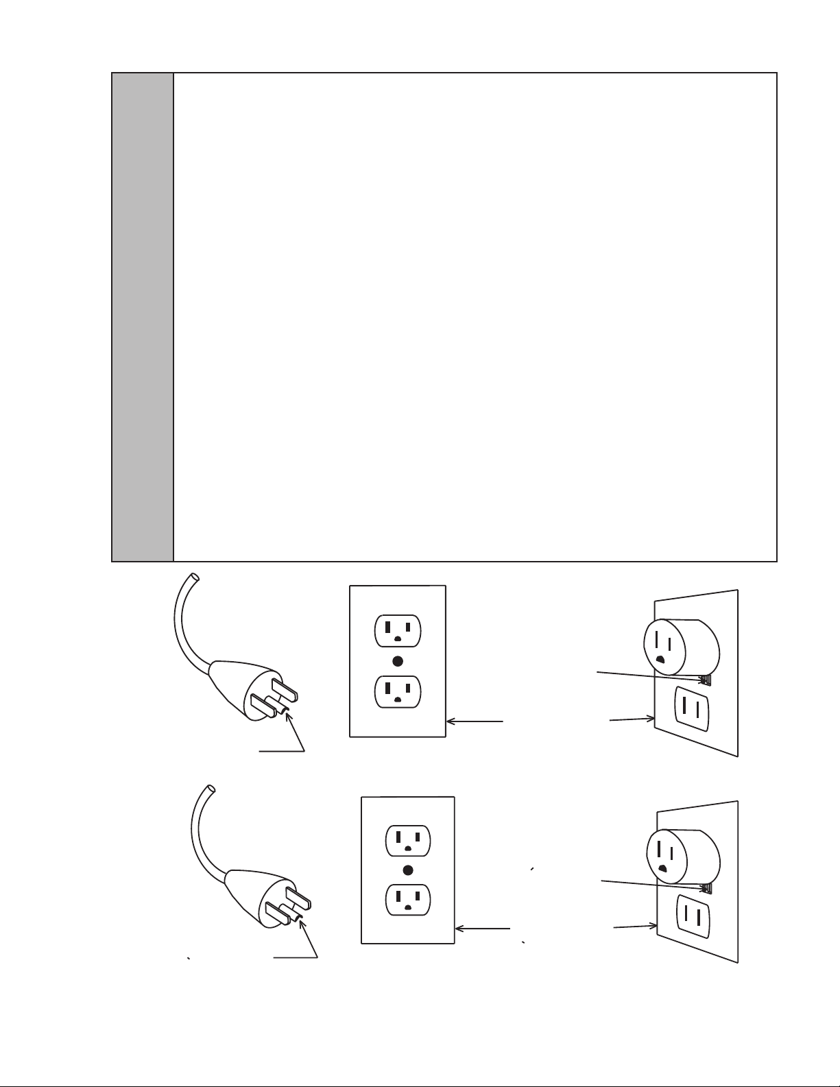
2.2 GROUNDING INSTRUCTIONS
GROUNDING WARNING THIS APPLIANCE MUST BE PROPERLY GROUNDED TO AVOID POSSIBLE FATAL
ELECTRICAL SHOCK OR SERIOUS INJURY TO THE OPERATOR. THE POWER CORD IS PROVIDED WITH A THREE
PRONG GROUNDED PLUG. IF A THREE HOLE GROUNDED ELECTRICAL OUTLET IS NOT AVAILABLE, USE AN
APPROVED METHOD TO GROUND THE UNIT. IN THE EVENT OF MALFUNCTION OR BREAKDOWN,
GROUNDING PROVIDES A PATH OF LEAST RESISTANCE FOR ELECTRIC CURRENT TO REDUCE THE RISK OF
ELECTRIC SHOCK. THIS APPLIANCE IS EQUIPPED WITH A CORD HAVING AN EQUIPMENT-GROUNDING PLUG.
THE PLUG MUST BE PLUGGED INTO AN APPROPRIATE OUTLET THAT IS PROPERLY INSTALLED AND GROUNDED IN ACCORDANCE WITH ALL LOCAL CODES AND ORDINANCES.
THIS APPLIANCE IS FOR USE ON A NOMINAL 120V (OR 230V, AS APPLICABLE) CIRCUIT, AND
HAS A GROUNDING PLUG THAT LOOKS LIKE THE PLUG ILLUSTRATED BELOW.
ADVERTENCIA, PUESTA A TIERRA ESTE APARATO DEBE ESTAR CORRECTAMENTE CONECTADO A TIERRA
PARA EVITAR POSIBLES DESCARGAS ELÉCTRICAS MORTALES O LESIONES GRAVES AL OPERADOR. EL CABLE
DE ALIMENTACIÓN ESTÁ DOTADO DE UN TRES PUNTAS TOMA DE TIERRA. SI UN AGUJERO DE TOMA DE
CORRIENTE CON CONEXIÓN A TIERRA DE TRES NO ESTÁ DISPONIBLE, UTILICE UN MÉTODO APROBADO PARA
LA UNIDAD. EN CASO DE MAL FUNCIONAMIENTO O AVERÍA, CONEXIÓN A TIERRA PROPORCIONA UNA VÍA DE
MENOR RESISTENCIA PARA LA CORRIENTE ELÉCTRICA PARA REDUCIR EL RIESGO DE DESCARGA
ELÉCTRICA. ESTE APARATO ESTÁ EQUIPADO CON UN CABLE QUE TIENE UN TIERRA DEL EQUIPO DE
F
ENCHUFE. EL ENCHUFE DEBE CONECTARSE A UN TOMACORRIENTE ADECUADO QUE ESTÁ INSTALADO Y
CONECTADO A TIERRA DE ACUERDO CON TODOS LOS CÓDIGOS LOCALES Y ORDENANZAS.
ESTE APARATO ES PARA USO EN UN NOMINAL DE 120V (O 230V, SEGÚN EL CASO) DE CIRCUITO, Y
TIENE UN ENCHUFE DE CONEXIÓN A TIERRA QUE SE PARECE AL ENCHUFE ILUSTRADO A CONTINUACIÓN.
EXIGENCES DE MISE À LA TERRE CET APPAREIL DOIT ÊTRE MIS À LA TERRE DE LA MANIÈRE
APPROPRIÉE AFIN D’ÉVITER DES CHOCS ÉLECTRIQUES MORTELS OU DES BLESSURES GRAVES À
L’OPÉRATEUR. LE CORDON D’ALIMENTATION EST FOURNI AVEC UNE FICHE À TROIS BROCHES POUR LA
MISE À LA TERRE. UTILISER UNE AUTRE MÉTHODE APPROUVÉE POUR METTRE L’APPAREIL À LA TERRE
LORSQU’UNE PRISE DE COURANT DE MISE À LA TERRE (TROIS TROUS) N’EST PAS DISPONIBLE. ADVENANT
UNE DÉFAILLANCE OU UN BRIS, LA MISE À LA TERRE FOURNIT UN TRAJET DE MOINDRE RÉSISTANCE POUR
LE COURANT ÉLECTRIQUE AFIN DE RÉDUIRE LE RISQUE DE CHOC ÉLECTRIQUE. CET APPAREIL EST ÉQUIPÉ
D’UN CORDON AYANT UNE FICHE DE MISE À LA TERRE. LA FICHE DOIT ÊTRE BRANCHÉE SUR UNE PRISE
APPROPRIÉE CORRECTEMENT INSTALLÉE ET MISE À LA TERRE CONFORMÉMENT AUX CODES AUX
RÈGLEMENTS LOCAUX.
CET APPAREIL DOIT ÊTRE UTI LISÉ SUR UN C IRCUIT DE 120 V (O U 230V EST D”APPLICATION) NOMINAL ET
COMPORTE UNE FICHE QUI RESSEMBLE À LA FICHE ILLUSTRÉE CI-DESSOUS.
GROUNDING
PIN
BROCHE DE MISE
A LA TERRE
METAL SCREW
COVER OF GROUNDED
OUTLET BOX
VIS METALLIQUE
COUVERCLE DU COFFRET
DE PRISE DE
COURANT MIS
A LA TERRE
5
Page 6

GROUNDING WARNING IMPROPER CONNECTION OF THE EQUIPMENT-GROUNDING CONDUCTOR CAN RE-
SULT IN A RISK OF ELECTRIC SHOCK. THE CONDUCTOR WITH INSULATION HAVING AN OUTER SURFACE THAT
IS GREEN, WITH OR WITHOUT YELLOW STRIPS, IS THE EQUIPMENT-GROUNDING CONDUCTOR. IF REPAIR OR
REPLACEMENT OF THE CORD OR PLUG IS NECESSARY, DO NOT CONNECT THE EQUIPMENT GROUNDING
CONDUCTOR TO A LIVE TERMINAL. CHECK WITH A QUALIFIED ELECTRICIAN OR SERVICEMAN IF THE GROUNDING INSTRUCTIONS ARE NOT COMPLETELY UNDERSTOOD, OR IF IN DOUBT WHETHER THE APPLIANCE IS
PROPERLY GROUNDED. DO NOT MODIFY THE PLUG PROVIDED WITH THE APPLIANCE. IF IT WILL NOT FIT THE
OUTLET, HAVE A PROPER OUTLET INSTALLED BY A QUALIFIED ELECTRICIAN.
ADVERTENCIA, PUESTA A TIERRA LA CONEXIÓN INCORRECTA DEL CONDUCTOR DE TIERRA DEL EQUIPO
PUEDE OCASIONAR UN RIESGO DE DESCARGA ELÉCTRICA. EL CONDUCTOR CON AISLAMIENTO QUE TIENE
UNA SUPERFICIE EXTERIOR VERDE, CON O SIN FRANJAS AMARILLAS, ES EL CONDUCTOR DE PUESTA A
TIERRA. SI LA REPARACIÓN O REEMPLAZAR EL CABLE O EL ENCHUFE ES NECESARIO, NO CONECTE EL
EQUIPO CONDUCTOR A TIERRA A UN TERMINAL CON CORRIENTE. CONSULTE A UN ELECTRICISTA CALIFICADO
O TÉCNICO DE SERVICIO SI LAS INSTRUCCIONES DE CONEXIÓN A TIERRA NO SE ENTIENDEN
F
COMPLETAMENTE, O SI EN DUDAN DE SI EL APARATO ESTÁ CORRECTAMENTE CONECTADO A TIERRA. NO
MODIFIQUE EL ENCHUFE QUE SE PROPORCIONA CON EL APARATO. SI NO ENTRA EN LA TOMA, PIDA A UN
ELECTRICISTA QUE INSTALE UNA ELECTRICISTA CALIFICADO.
EXIGENCES DE MISE À LA TERRE UN BRANCHEMENT INAPPROPRIÉ DU CONDUCTEUR DE MISE À LA
TERRE PEUT CAUSER UN RISQUE DE CHOC ÉLECTRIQUE. LE CONDUCTEUR DE MISE À LA TERRE EST CELUI
DONT L’ISOLANT A UNE SURFACE EXTÉRIEURE VERTE (AVEC OU SANS BARRES JAUNES). S’IL EST
NÉCESSAIRE DE RÉPARER OU DE REMPLACER LE CORDON OU LA FICHE, NE PAS BRANCHER LE
CONDUCTEUR DE MISE À LA TERRE SUR UN TERMINAL SOUS TENSION. FAIRE APPEL À UN ÉLECTRICIEN OU
UN RÉPARATEURQUALIFIÉ SI LES INSTRUCTIONS DE MISE À LA TERRE NE SONT PAS COMPLÈTEMENT
COMPRISES OU SI L’APPAREIL NE SEMBLE PAS ÊTRE MIS À LA TERRE DE LA MANIÈRE APPROPRIÉE. NE
JAMAIS MODIFIER LA FICHE FOURNIE AVEC L’APPAREIL. SI ELLE NE S’INSÈRE PAS DANS LA PRISE,
DEMANDER À UN ÉLECTRICIEN QUALIFIÉ D’INSTALLER UNE PRISE APPROPRIÉE.
A. Check the serial number plate for correct electrical requirements of the unit. Do not plug into the
electrical outlet unless the current shown in the serial number plate agrees with local current
available.
B. A separate electrical circuit must be supplied for each carbonator.
C. Do not use extension cords or “gang” together with other electrical devices on the same outlet.
3. OPERATING INSTRUCTIONS
A. Before installing, make any desired conguration changes. Refer to conguration section.
B. Connect 3/8” exible pressure tubing, or larger, from water supply to pump inlet. Do not connect
to a hot water or soft water source. A shutoff valve and screen (minimum 100 mesh), should be
installed in water supply line to carbonator. A water lter may also be necessary in water supply
line to carbonator, depending on local conditions. Water pressure entering the pump should be at
a minimum of 25 PSIG (0.172 MPA); recommended water pressure is 50 PSIG (0.345 MPA), and
should never exceed CO2 pressure. If necessary, install a regulator.
C. Connect CO2 pressure supply to CO2 inlet on carbonator tank, with normal operating pressure at
105 PSIG (0.720 MPA). Do not exceed 120 PSIG (0.830 MPA). If excessive foam in drink is
present, reduce CO2 pressure to approximately 90 PSIG (0.620 MPA).
D. Connect carbonator water outlet to dispensing system. If only one tank outlet is used, cap remain-
ing with stainless steel cap and are washer, PNs 01-0212 and 05-0017. To avoid contamination of
potable liquids, do not connect copper tubing or tting between the discharge tting of carbonator
tank and dispenser.
E. Open pressure relief valve by moving yellow lever to vertical position.
F. To remove air, turn water supply on and ll tank until water can be seen coming out of pressure
relief valve.
G. Close pressure relief valve by moving yellow lever to horizontal position.
H. Turn on CO2 supply and adjust to correct pressure.
I. If electrical requirements have been met, plug in carbonator.
J. Check for CO2 and water leaks.
K. Open a dispensing valve. Allow carbonator to cycle several times, turning motor OFF and ON to
ush system.
6
Page 7

4. USER MAINTENANCE INSTRUCTIONS
4.1 INSPECTIONS
A. Periodically inspect for CO2 or water leaks. Perform maintenance as necessary.
B. Inspect and clean pump strainer.
5. CLEANING AND REPLACEMENT
5.1 CO2 CHECK VALVE
A. Unplug power cord.
B. Shut water supply OFF to pump.
C. Turn CO2 supply OFF and set CO2 pressure regulator at 0 PSIG.
D. Disconnect CO2 supply line from CO2 check valve.
WARNING DO NOT PROBE VALVE WITH ANY OBJECT.
ADVERTENCIA NO HAGA PRUEBAS VÁLVULA CON UN OBJETO.
!
E. Cover end of check valve with soap suds. If check valve is defective, gas bubbles will appear. If
F. Release pressure in tank, using relief valve.
G. Disassemble check valve body and components. Inspect spring and o-rings. Re place as
required.
H. Reassemble and reinstall check valve.
I. Reconnect CO2 supply line to CO2 check valve.
J. Follow start up procedure to put carbonator back into operation.
5.2 BACKFLOW PREVENTER
!
A. Unplug power cord.
B. Shut water supply OFF to pump.
C. Set CO2 pressure at 100 to 125 PSIG (0.690 to 0.860 MPA).
D. Disconnect stainless steel water line from water inlet check valve. Do not loosen check valve
E. Cover end of check valve with soap suds. If check valve is defective, gas bubbles will appear.
F. Turn CO2 pressure OFF. Release pressure in tank, using relief valve.
G. Replace the backow preventer.
H. Reconnect stainless steel line to water inlet check valve.
I. Follow start up procedure to put carbonator back into operation.
5.3 PUMP STRAINER SCREEN
A. Unplug power cord.
B. Shut water supply OFF to pump.
C. Unscrew brass plug on pump, and remove strainer from pump.
D. Inspect and clean, or replace, strainer screen.
E. Reinstall strainer, and tighten brass plug.
F. Turn water supply ON.
G. Check for leaks. If a leak is detected, carefully tighten brass plug.
H. Plug power cord into electrical outlet.
AVERTISSEMENT NE JAMAIS SONDER LE CLAPET AVEC UN OBJET QUELCONQUE.
a leak is detected, continue with the following steps.
WARNING IF THE FIRST CHECK ON THE BACKFLOW PREVENTER FAILS, CARBONATED WATER WILL LEAK
FROM THE VENT ON THE VALVE. DO NOT DISASSEMBLE THE BACKFLOW PREVENTER. REPLACE BY
ORDERING PART NUMBER 17-0611. DO NOT DISABLE THE BACKFLOW PREVENTER.
ADVERTENCIA SI LA PRIMERA COMPROBACIÓN DE LA VÁLVULA ANTIRRETORNO FALLA, AGUA CON GAS SE
ESCAPARÁ DE LA REJILLA DE VENTILACIÓN DE LA VÁLVULA. NO DESARME LA VÁLVULA ANTIRRETORNO.
REEMPLAZAR POR PEDIR EL NÚMERO DE PIEZA 17-0611. NO DESACTIVE LA VÁLVULA ANTIRRETORNO.
AVERTISSEMENT SI LE PREMIER CONTRÔLE DU DISCONNECTEUR HYDRAULIQUE ÉCHOUE, DE L’EAU
CARBONÉE FUIRA PAR L’ÉVENT DU CLAPET. NE JAMAIS DÉSASSEMBLER LE DISCONNECTEUR HYDRAULIQUE.
COMMANDER UN NOUVEAU DISCONNECTEUR HYDRAULIQUE, Nº DE PIÈCE 17-0611. NE JAMAIS METTRE LE
DISCONNECTEUR HYDRAULIQUE HORS FONCTION.
assembly.
If a leak is detected, continue with the following steps. If no leak is detected, proceed to Step I
below.
7
Page 8

5.4 REPLACING PROBE
A. Unplug power cord.
B. Shut water and CO2 gas supplies OFF.
C. Relieve pressure in tank using relief valve.
D. Remove cover and unplug probe leads from PC board.
E. Unscrew probe from top of tank.
F. Screw new probe into top of tank. Be sure to install white plastic washer as a water tight seal
will not be obtained without the washer.
G. Connect probe leads to PC board as follows:
Green G
Black LO
White HI
H. Slide probe strain relief into slot and replace cover.
I. Follow start-up procedure for putting carbonator back into operation.
5.5 REPLACING PC BOARD
A. Unplug power cord.
B. Remove cover from PC board enclosure.
C. Unplug probe, power cord and motor cord leads from PC board.
D. Remove PC board assembly.
E. Congure new board, refer to conguration section.
F. Install new PC board and secure with screws.
G. Connect push leads and secure to PC board as follows:
Probe Power Cord Motor Cord
Green G Black 1 Black 3
Black LO White 2 White 4
White HI
H. Replace cover.
I. Plug in power cord.
J. Test diagnostic switch connector.
8
Page 9

6. CONFIGURATION
The new carbonator PCB assemblies 64-5076 (230V) and 64-5081 (115V) have two conguration
switches, located between the Power and Timeout LEDs:
On Off
These switches can be switched with a small screwdriver or a ballpoint pen. Toward the edge of the board
is ON, toward the center is OFF.
Pos 1 — Enable
Diagnostic/Reset Switch
Pos 2 — Enable
Timeout Auto-Retry
ON OFF
Switch must be connected to J9
Pressing and holding the switch
connected to J9 will test the motor.
Releasing the switch will reset any
timeout.
If the tank fails to ll within 3
minutes, the carbonator times
out and will attempt to ll itself
every 15 minutes for 3 hours. If it
succeeds, normal operation will
resume. The timeout LED will blink
slowly within the 3 hours, then
quickly after.
J9 may be empty (no jumpers
required). Any connected switch is
ignored.
If the tank fails to ll within 3
minutes, the carbonator times out
and never retries. The
timeout LED will turn on
continuously when the carbonator
times out.
9
Page 10

7. TROUBLESHOOTING
PC Board Self-Diagnostics
Follow instruction label on enclosure cover to help determine if probe, motor or board is faulty.
TROUBLE CAUSE REMEDY
7.1 Motor does not start. (Motor hums.) A. Pump binding.
A. Rotate pump slightly to free binding. If
this fails, replace pump.
B. Open winding ineld
7.2 Motor does not start. (Motor does not
hum.)
7.3 Motor runs continuously. A. Restriction in inlet water check valve.
A. Overload by pump binding.
B. Fuse or circuit breaker.
C. Faulty motor.
D. Faulty PC board.
E. Faulty probe.
F. Timeout feature has activated. This
happens when the carbonator runs longer
than three minutes without the demand
for water being met.
B. Restriction in pump.
C. Faulty board or probe.
B. Replace motor.
A. Let motor cool and free pump binding.
B. Replace fuse or reset circuit breaker.
C. Replace motor.
D. Replace PC board.
E. Replace probe.
F. Reset power to the carbonator or press
and release reset switch.
A. Disassemble inlet water check valve
and clean.
B. Clean strainer or replace pump.
C. Replace board or probe.
7.4 Pressure relief valve releases water. A. Faulty relief valve. A. Replace relief valve.
7.5 Low Carbonation. A. Low CO2 pressure.
B. Leaking CO2 supply line.
7.6 Foamy product. A. Over carbonation. A. Reduce CO2 pressure.
A. Increase CO2 pressure or replace
CO2 tank.
B. Locate leak and repair.
10
Page 11

Basic Go/No Go Carbonator Control Test
Part Number 06-1236/01 (shown below) is found on the cover of the carbonator assembly. It provides a
basic troubleshooting procedure to determine if the liquid level control is operating properly. The
procedure will help isolate problems to the probe, motor or PC Board.
8. ILUSTRATIONS, PARTS LISTINGS, AND WIRING DIAGRAMS
8.1 CHECK VALVE ASSEMBLY
1
2 3
Item Part No. Description
1 17-0342 CO2 Check Valve Assy
2 01-0669 Body
3 02-0005 O-Ring
4 01-0689 Sleeve
8.2 WIRING DIAGRAM (PN 06-0266/02)
4
5
6
Item Part No. Description
5 01-0674 Ball
6 03-0021 Spring
7 02-0003 O-Ring
GREEN
BLACK
WHITE
J4
J3
L2
7
PROBE
LOW VOLTAGE
WHITE
BLACK
GREEN
HI LO
PC BOARD
G
11
L1
MOTOR
115 VAC
115 V or 220 V
WHITE
BLACK
GREEN
Page 12

8.3 CARBONATOR TANK
2
1
3
13
16
14
11
12
15
11
17
18
33
19
4
6
34
5
7
9
10
9
8
2
32
31
30
29
28
27
26
25
24
21
9
22
23
20
18
Item Part No. Description
1 05-0528-01 Cover, Carb LLC
2 04-0470 Screw, 6-19X0.500, PHD
3 12-0241 Boot, U-1403-APEM
4 06-1289 Label, Test Switch, Carb
06-3400 Label, Test/Reset Switch
5 06-1236/01 Label, Troubleshoot
7 04-0836/01 Washer, Lock, Internal Tooth
8 04-0049 Nut, Hex, 8-32, SS
9 04-0297 Nut, Hex, 8-32, KEPS, SS
10 06-0266/02 Label, Wiring Diagram
11 05-0017 Washer, Seal, Flare, Nylon, 3/8
12 87-0026 Tank Assy, Carb, 3/8, Flare
13 48-2386 Tubing Assy, Water, 3/8
14 17-0611 Check Valve, Vented, BR,
ABCO
17-0611-01 Check Valve, SS
15 01-0111 Adapter, BR, 3/8 x 3/8
16 86-0085 Pump Assy, Water,
Replaceable
17 07-0017/01 Clamp with Screw, ZP
18 04-0032/01 Nut, Nylock, 1/4-20, SS
19 06-0075-01 Nameplate, Vinyl, PN/SN/ ELEC
20 07-0199/01 Plate, Base Probe, Carb
Item Part No. Description
21 04-1361 Screw, 8-32 x 0.75, PH, SS
22 04-0247 Isolator, 1/4-20 Single Stud
23 52-0588 Power Cord Assy
52-1898 Cord Assy, Carb, 220V
24 04-0033/01 Washer, Flat, 4 x 0.065 x
0.281 ID
25 04-0520/01 Screw, 1/4-20 x 0.500, HHD, SS
26 91-0008 Motor, Carb, 1/3HP, 115V/60A
91-0011/01 Motor, Carb, 1/3HP, 220V/50Hz
27 52-0585 Cord Assy, Motor
28 13-0028 Relief, Strain, 7/8 DIA
29 13-0008 Bushing Relief, HEYCO, 1200
30 13-0026 Strain Relief, Small
31 05-0529-01 Enclosure, Carb, Control, Self
32 64-5000 PCB Assy
64-2962 PCB Assy, 220V
64-2962-01 PCB Assy, 220V w/Reset
64-5076 PCB Assy, 220V w/Auto reset
64-5081 PCB Assy, w/Auto reset
33 54-0066 Relief Valve Assy, Plastic
34 06-2590 Label, “Reset Button”
35 52-0590/01 Probe Assy
12
Page 13

NOTES
9. APPLIANCE DISPOSAL
To prevent possible harm to the environment from improper disposal, recycle the unit
by locating an authorized recycler or contact the retailer where the product was pur
chased. Comply with local regulations regarding disposal of the refrigerant and
insulation.
13
Page 14

Lancer Corp.
800-729-1500
Technical Support/Warranty: 800-729-1550
custserv@lancercorp.com
lancercorp.com
 Loading...