

Page 1
INSTALLATION AND SERVICE MANUAL
FOR
LANCER SERIES TD 1700
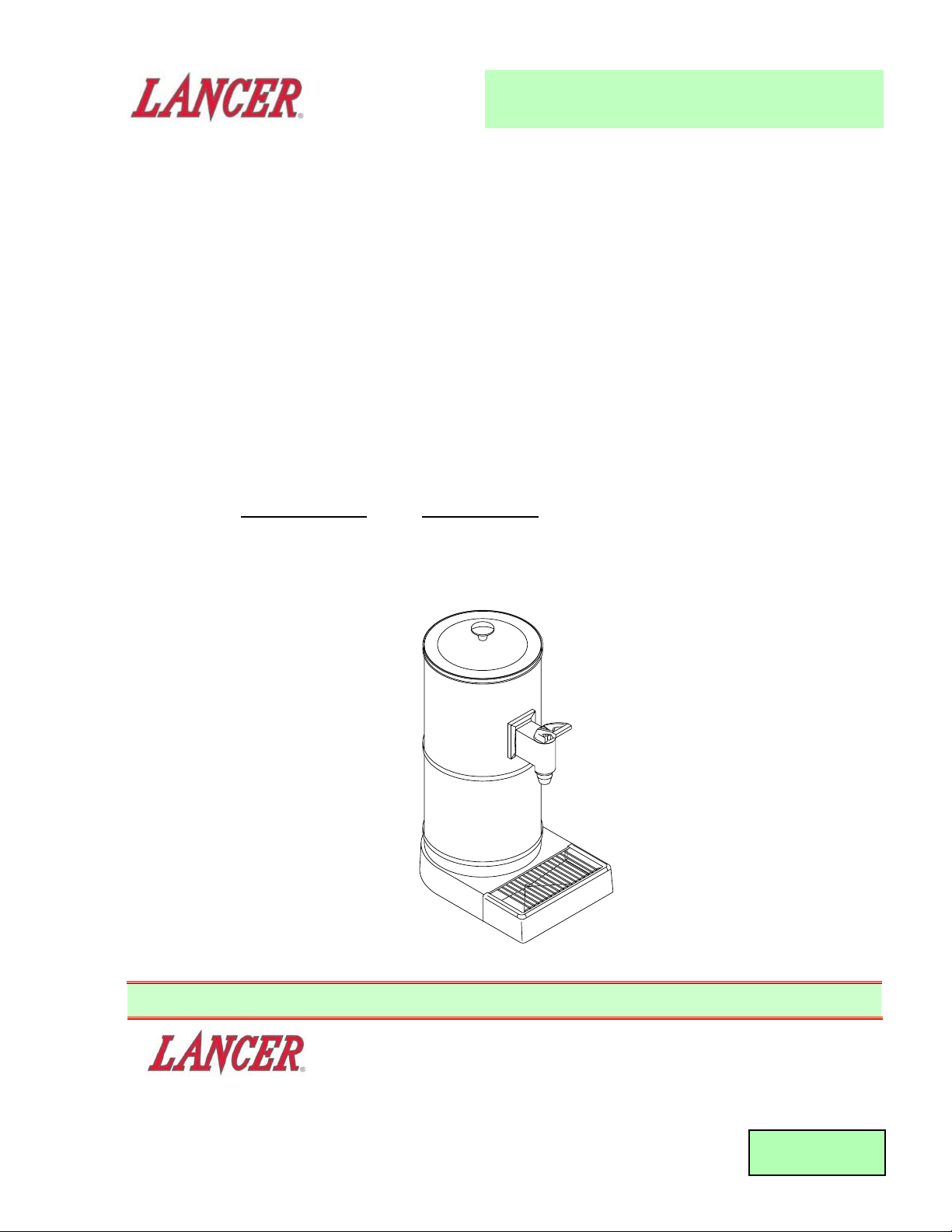
TEA DISPENSER
PART NUMBER
DESCRIPTION
85-1711 TEA DISPENSER, 115V, 60Hz
85-1712 TEA DISPENSER, 230V, 50HZ
REV: 10/28/98
P.N. 28–0199/01
FAX ENGINEERING: • 210-310-7096
"Lancer" is the registered trademark of Lancer • Copyright — 1998 by Lancer, all rights reserved
This Manual supersedes Installation and Service Manual, 28-0199, dated 02/07/94
Please refer to the Lancer web site (www.lancercorp.com) for
information relating to Lancer Installation and Service Manuals,
Instruction Sheets, Technical Bulletins, Service Bulletins, etc.
6655 LANCER BLVD. • SAN ANTONIO, TEXAS 78219 USA • (210) 310-7000
FAX SALES
• NORTH AMERICA – 210-310-7245 • INTERNATIONAL SALES – 210-310-7242 • CUSTOMER SERVICE – 210-310-7242 •
• LATIN AMERICA – 210-310-7245 • EUROPE – 32-2-755-2399 • PACIFIC – 61-8-8268-1978 •
Page 2

T
ABLE OF CONTENTS
TABLE OF CONTENTS ......................................................................................................................................I
SPECIFICATIONS...............................................................................................................................................I
1. INSTALLATION ...........................................................................................................................................1
1.1 RECEIVING........................................................................................................................................1
1.2 UNPACKING ......................................................................................................................................1
1.3 SELECTING A COUNTER LOCATION..............................................................................................1
1.4 WATER SUPPLY................................................................................................................................1
1.5 ELECTRICAL SUPPLY ......................................................................................................................1
1.6 INSTALLATION ..................................................................................................................................1
2. SYRUP AND WATER RATIO ADJUSTMENT.............................................................................................2
2.1 PREPARING DISPENSER FOR ADJUSTMENT...............................................................................2
2.2 ADJUSTMENT PROCEDURE ...........................................................................................................2
3. CLEANING AND MAINTENANCE ..............................................................................................................3
3.1 CLEANING INFORMATION ...............................................................................................................3
3.2 REQUIRED CLEANING EQUIPMENT...............................................................................................3
3.3 CLEANING AND SANITIZING PROCEDURE ...................................................................................4
4. REMOVING DISPENSER FROM SERVICE ...............................................................................................4
5. SERVICE AND TROUBLESHOOTING .......................................................................................................5
6. DISPENSER TROUBLESHOOTING GUIDE ...........................................................................................5-6
7. ILLUSTRATIONS AND PARTS LISTINGS .................................................................................................7
7.1 LANCER TEA DISPENSER ASSEMBLY ...........................................................................................7
7.2 LANCER TEA DISPENSER - VALVE ASSEMBLY (PN 19-0137) ......................................................8
7.3 LANCER TEA DISPENSER - NOZZLE EXTENSION ASSEMBLY (PN 54-0132) .............................9
SPECIFICA
TIONS
DIMENSIONS
Width 10 inches (25.4 cm)
Depth 14 7/8 inches (37.78 cm)
Height 23 7/8 inches (60.64 cm)
WEIGHT
Shipping 20 lbs (9.1 kg)
Operating 12.5 lbs (5.68 kg)
ELECTRICAL RATING
0.5 AMP
24 VAC
60 HZ
NOTE
Power supplied to dispenser by a remote transformer which converts 115 VAC (for PN 85-1711)
or 230V (for PN 85-1712) to 24 VAC.
SUPPLY CONNECTIONS
Water 3/8 inch (9.52 mm) barb
Syrup 3/8 inch (9.52 mm) barb
FEATURES
• Cup rest and drip pan are readily removable for cleaning.
NOTE
Drip pan drain is capped at the factory. Cap needs to be removed if connected to permanent drain.
• Nozzle extension assembly is readily removable for cleaning.
• Dispensing valve is readily accessible for inspection, cleaning and servicing.
i
Page 3

1. INSTALLATION OF LANCER TEA DISPENSER
1.1 RECEIVING
Each unit is completely tested under operating conditions and thoroughly inspected before
shipment. At the time of shipment, the carrier accepts the unit, and any claim for damage must be
made with the carrier. Upon receiving unit(s) from the delivering carrier, carefully inspect carton(s)
for visible indication(s) of damage. If damage exists, have carrier note the same on the bill of
lading and file a claim with the carrier.
1.2 UNPACKING
A. The Lancer Tea Dispenser is shipped in a corrugated shipping carton.
B. Carefully remove the corrugated shipping carton.
C. Check to see that the following items are included:
• Tea Dispenser
• Remote Transformer
• Installation Kit
D. Inspect items for concealed damage. If evident, notify delivering carrier and file a claim against
same.
1.3 SELECTING A COUNTER LOCATION
A. Select a counter location which is close to a properly grounded electrical outlet, and a water
supply that meets the requirements specified in Section 1.4 below.
1.4 WATER SUPPLY
A. The dispenser requires a minimum water flowing pressure of 40 PSI.
B. Water pipe connections and fixtures directly connected to a potable water supply shall be sized,
installed, and maintained according to federal, state and local laws.
1.5 ELECTRICAL SUPPLY
W
ARNING
THE POWER SUPPLY MUST BE PROPERLY ELECTRICALLY GROUNDED TO AVOID
POSSIBLE ELECTRICAL SHOCK OR SERIOUS INJURY TO THE OPERATOR. THE POWER
CORD IS PROVIDED WITH A THREE PRONG GROUNDED PLUG. IF A THREE-HOLE
GROUNDED ELECTRICAL OUTLET IS NOT AVAILABLE, USE AN APPROVED METHOD TO
GROUND THE UNIT.
A. The dispenser requires connection to a properly grounded electrical source: 115V, 60HZ (for
PN 85-1711) or 230V, 50HZ (for PN 85-1712).
NOTE
In the event more than one dispenser is installed, each dispenser should be on a separate 15
amp fused circuit.
B. Power is supplied to each dispenser by the remote transformer (included in Installation Kit)
which converts 115V (for PN 85-1711) or 230V (for PN 85-1712) to 24 VAC.
1.6 INSTALLATION
A. Place Tea Dispenser on counter top. Lay Tea Dispenser on its side to expose product supply
and electrical connections.
B. Identify supply connections in channel on underside of base. The water connection is a 3/8"
barb fitting, and the syrup connection is a 3/8" barb fitting.
C. Thoroughly flush all incoming lines before connecting (see Section 3.3, Cleaning and Sanitizing
Procedure). Avoid putting excessive strain on the lines to the unit; use sufficient line lengths.
D. Identify electrical connector in channel on underside of base.
E. Connect dispenser connector to output of remote transformer.
F. Connect input cord on remote transformer to properly grounded electrical source.
G. Turn Tea Dispenser upright and place in desired location.
1
Page 4
2
H Secure Tea Dispenser to counter top with the four (4) #10 Mounting Screws and Wingnuts
included in the Installation Kit.
NOTE
The Lancer Tea Dispenser Template (PN 28-0346) is included in the Installation Kit.
I. Remove lid from dispenser by unscrewing the knob.
J. Turn on water and syrup supplies. Check for leaks.
NOTE
When using Figal Syrup Supply Tanks, pressurize with clean air or Nitrogen (not CO
2).
K. Check operation of unit by activating the handle on the nozzle extension portion of unit.
L. Check dispensing valve for proper flow ratio (see Section 2).
M. Replace lid and secure with knob.
2. SYRUP AND WATER RATIO ADJUSTMENT
2.1 PREPARING DISPENSER FOR ADJUSTMENT
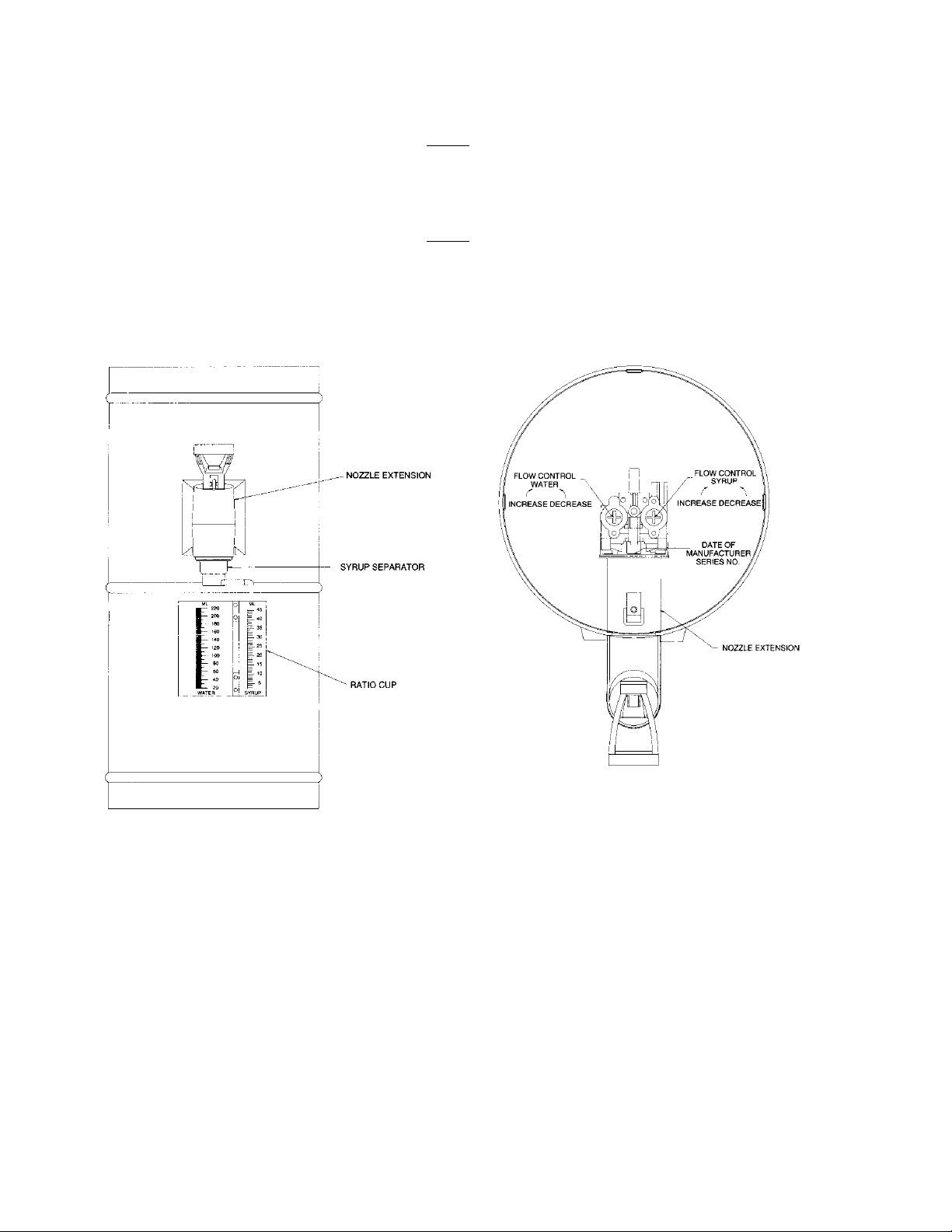
A. Remove nozzle from nozzle extension by twisting it to the left and pulling downward. Remove
diffuser by pulling downward.
B. Replace the nozzle and diffuser with the syrup separator (see Figure l). Push the syrup
separator upward and twist it to the right.
2.2 ADJUSTMENT PROCEDURE
A. Hold ratio cup under the syrup separator (see Figure l). Hold small chamber marked "4.50 to 1"
under the syrup spout.
B. Actuate the valve until approximately five (5) ounces (148 ml) of water fills the main chamber.
1. Set the ratio cup on a level surface, and note whether the syrup level is above or below the
water level.
Front View, Syrup Separator and Ratio Cup
Figure 1
View Looking Down, Valve Adjustment
Figure 2
Page 5

2. If the syrup and water are at the same level, the ratio is properly adjusted. If the syrup and
water are not at the same level, continue with the valve adjustment procedure below.
C. Remove the lid from the dispenser by unscrewing the knob.
D. Locate the two flow control adjustment screws on the front of the valve (see Figure 2). The
water side flow control adjustment screw is on the left. The syrup side flow control adjustment
screw is on the right.
NOTE
The water side flow control is factory preset to dispense 2 1/2 fluid ounces per second
(74 ml/sec) and should require no adjustment.
E. Increase or decrease the syrup flow to cause the two liquid levels to become even in the ratio
cup. To increase syrup flow, turn the adjustment screw in (clockwise); to decrease flow, turn the
screw out (counter clockwise).
F. Rinse out the ratio cup with water.
G. Repeat steps E and F until syrup and water levels are even.
H Remove the syrup separator, replace the diffuser and nozzle, and reinstall the lid on the
dispenser.
3. CLEANING AND MAINTENANCE
NOTE:
The dispenser must be cleaned and sanitized after installation is complete and, thereafter as required by
state and local authorities, or every six months, minimum.
3.1 CLEANING INFORMATION
A. Clean external surfaces with mild soap and warm water. Rinse with clean water.
B. Remove four (4) Wingnuts and Mounting Screws securing Tea Dispenser to counter. Clean
under unit as required.
C. Do NOT use strong bleaches or detergents. They tend to discolor and corrode various
materials.
D. Do NOT use steel wool, scouring pads, abrasives, etc., on the dispenser.
E. Do NOT use hot water exceeding a temperature of 140
o
F (60oC). This may damage certain
materials.
F. Continuous maintenance is a basic requirement for proper operation and sanitation of this unit.
G. Daily routine cleaning should be performed. This should consist of washing the cup rest and
drip pan in cleaning solution. Then rinse with tap water. Wipe all splash areas clean, using a
damp cloth soaked in cleaning solution.
B. Reinstall Tea Dispenser to counter location. Secure with four Mounting Screws and Wingnuts
removed in Step A above.
3.2 REQUIRED CLEANING EQUIPMENT
A. Prepare a cleaning solution consisting of two (2) ounces of CHECK-MARK DDS-164 (NCH
Corp./Kernite) per gallon of tap water (200 ppm Quaternaries) at 75
o
F. An equivalent cleaning
solution may be used if prepared in accordance with the manufacturer’s instructions.
Approximately 3 1/2 gallons should be prepared.
B. Prepare a sanitizing solution consisting of one (1) ounce of CHECK-MARK DDS-185 (NCH
Corp./Kernite) per four (4) gallons of tap water (200 ppm Quaternaries) at 75
o
F. An equivalent
sanitizing solution may be used if prepared in accordance with the manufacturer’s instructions.
Approximately 3 1/2 gallons should be prepared.
C. Two pressure tanks are required. Use one tank for the cleaning solution, and one for the
sanitizing solution.
D. Other:
• Clean cloth towels
• Bucket
• Small brush (PN 22-0017, included with installation kit)
• Extra nozzle
3
Page 6

3.3 CLEANING AND SANITIZING PROCEDURE
NOTE
Routine cleaning should be performed prior to cleaning and sanitizing.
Cleaning and sanitizing are not required for potable water circuits. The potable water lines
should remain connected during the cleaning and sanitizing procedures for the syrup circuits to
avoid contamination.
A. Neutralize pressure and disconnect syrup container from valve product line. Remove product
from the line by purging with carbon dioxide (CO
2). Purge completion is evident by sputtering
from the valve.
B. Clean the line and fitting with cleaning solution (prepared IAW Section 3.2), and rinse with clean,
room temperature water to remove all traces of residual product.
C. Attach valve product line to the pressure tank containing the cleaning solution. Pressurize and
fill the syrup line by activating the valve. Make sure the line is full by running at least three (3)
gallons (11 liters) through the valve and allow to stand pressurized for at least 10 minutes.
D. Flush the cleaning solution from the line with clean water. Continue flushing until testing with
phenolphthalein shows the rinse water to be free of residual detergent.
E. Attach the valve line to the pressure tank containing the sanitizing solution (prepared IAW
Section 3.2). Pressurize and fill the lines with sanitizing solution. Make sure the lines are
completely filled by running at least three (3) gallons (11 liters) through the valve and allow to
stand pressurized for at least 10 minutes.
NOTE
A sufficient amount of sanitizing solution should be placed in a separate container for the
purpose of cleaning and sanitizing the nozzle and diffuser.
F. Twist off the mixing nozzle and remove the diffuser from under the nozzle extension. Wearing
sanitary gloves, clean and sanitize these items, allowing them to remain in the sanitizing
solution for at least 10 minutes. Then, reinstall the nozzle and diffuser without rinsing them.
NOTE
Please note that a fresh water rinse cannot follow sanitization of equipment being actively
operated. Purge only with CO
2 or the end use product. This is an NSF requirement.
G. Purge the sanitizer from the syrup line with carbon dioxide.
H. Reconnect the syrup container to the valve line and ready the dispenser for operation.
W
ARNING
FLUSH SANITIZING SOLUTION FROM SYRUP SYSTEMS AS INSTRUCTED. RESIDUAL
SANITIZING SOLUTION LEFT IN SYSTEM COULD CREATE HEALTH HAZARD.
I. Draw drinks to refill the line and flush the sanitizing solution (chlorine solution) from the
dispenser. Taste the beverage to verify that there is no off-taste.
4. REMOVING DISPENSER FROM SERVICE
4.1 If it becomes necessary to remove a dispenser from service, complete the following procedure.
A. Neutralize pressure on water and syrup supply lines. Disconnect water and syrup lines from the
dispenser.
B. Connect suitable pressure tank containing sanitizing solution (prepared IAW Section 3.2) to CO
2
supply and syrup inlet line. Then flush sanitizing solution through system. When chlorine
solution appears, disconnect tank and allow to stand five (5) minutes.
CAUTION
INSURE ALL SANITIZING SOLUTION IS DRAINED OR BLOWN OUT OF SYSTEM. ALL
PRODUCT TUBES MUST BE FREE OF SANITIZING SOLUTION AND OR WATER BEFORE
SHIPPING OR STORING UNIT. RESIDUAL WATER IN DISPENSER (STORED IN A FREEZING
ENVIRONMENT) CAN CAUSE INTERNAL DAMAGE TO THE UNIT.
C. Connect clean potable water to syrup inlet line. Then, flush system thoroughly to remove all
traces of chlorine.
4
Page 7

D. Connect CO2 supply to syrup inlet line and force all water out of syrup line with CO2 pressure.
E. Connect CO2 supply to water inlet line and force all water out of water line with CO2 pressure.
F. Place a disposable plastic bag over dispensing valve nozzle (or entire dispenser), and syrup
and water line fittings. Secure in place with tape.
5. SERVICE AND TROUBLESHOOTING
5.1 Problems found in the operation of the dispenser can be solved by using the procedures listed
below, the Troubleshooting guide, or by calling Lancer Customer Service or the Coca-Cola
Company at the numbers listed below.
5.2 Before seeking repair assistance, check the following.
A. Does the syrup container contain syrup?
B. Is the syrup line properly connected to the syrup tank or bag?
C. Is the syrup outlet line properly connected to the pump stand fitting ( BIB only)?
D. Is the CO
2 outlet line properly connected to the pump stand fitting (BIB only)?
E. Is the dispenser unplugged?
F. Do the CO
2 cylinders contain adequate CO2 supply?
G. Are the CO2 regulators properly set?
H. Are the circuit breakers in the "OFF" position, or electrical fuses blown?
I. Service for dispensing systems can be obtained by calling the following:
1. The Coca-Cola Company at 1-800-241-COKE (2693)
2. Lancer at 1-800-729-1565
Monday through Friday, 7:30 a.m. - 5:30 p.m., CST.
6. DISPENSER TROUBLESHOOTING GUIDE
The following chart is designed to aid in correcting Tea Dispenser problems. Indicated corrective actions
should be made by qualified dispensing service personnel only.
PROBLEM
CAUSE CORRECTIVE ACTION
1. No product dispensed A. No electricity to dispenser. A. Check fuse or circuit breaker and
from valve. replace or reset as applicable.
*If circuit opens again, locate short
in electrical system and correct.
B. No gas pressure on system. B. Check gas pressure(s) on CO2
tank(s) - valve open?
C. Transformer not connected, C. *Check output transformer. Should
or defective transformer. be 24 VAC. Replace if defective.
D. Loose or defective D. *Check all connections between
connections. transformer and dispensing valve.
Tighten if loose. If defective,
Replace.
2. Only water dispensed - A. Syrup tank is empty (usually A. *Replace or fill syrup tank.
no syrup. accompanied by hissing
and sputtering).
B. Gas or liquid syrup tank B. Check that both disconnects are
disconnects not secure. locked in position.
C. Syrup or gas lines to tank C. Adjust lines or replace.
are kinked.
D. Syrup mounting block shutoff D. Open valve.
valve closed.
E. Lack of pressure to syrup E. Check secondary regulator. Adjust
tanks. to 60 PSIG (414 KPA) if sugar
based. Adjust to 15 PSIG
(103 KPA) if sugar free. For BIB,
adjust to 60 PSIG for all pumps.
*Servicing must be performed by
(Continued next page) qualified service personnel.
5
Page 8

(Continued from previous page) F. Dip tube in syrup tank blocked. F. Remove both quick disconnects
from syrup container. Depressurize
tank through relief valve. Remove
syrup and wash tank. Interchange
quick disconnects and pressurize to
the syrup out connection to remove
debris from dip tube. Clean tank
again. Upon completion, restore
disconnects to their original
locations.
G. Dispensing valve port blocked. G. Back-flush system.
3. Only syrup dispensed, A. Water mounting block shutoff A. Open valve.
no water. valve closed.
B. Water supply off. B. Open water supply valve.
C. Inadequate water supply C. Check pressure. Consider
pressure. installation of water pressure
booster kit.
4. Ratio cannot be set. A. Inadequate water supply A. Turn water flow control (left side) to
pressure. full open (CW). Measure flow rate.
If greater than 2.5 oz/sec
(74 ml/sec), adjust water to
2.5 oz/sec., then adjust syrup. If
less than 2.5 oz/sec with flow
control at maximum setting, adjust
syrup to proper ratio with water at
maximum setting.
B. Product lines not installed B. Ensure water supply is connected
properly. to water inlet and syrup supply is
connected to syrup inlet.
5. Bad taste or odor. A. Dirty valve. A. Clean nozzle and diffuser
thoroughly.
B. Foreign substance in water. B. If water is free of impurities, it is
tasteless and odorless. Clean and
flush the system, and service the
water filter. (If the system does not
have a water filter, consider
installing one.)
C. Contaminated ice. C. Same conditions may exist in ice as
in plain water. Check with ice
machine service personnel to have
filter installed. Clean ice bin or
chest.
D. Contaminated syrup. D. Clean and sanitize lids, lid gaskets,
tanks and syrup/CO
2 couplers per
tank manufacturers or maintenance
instructions.
E. Impure CO2 gas. E. Carbon dioxide gas is odorless,
colorless and tasteless. If CO2 gas
should contain any oil or sludge
from filling tanks, a bad taste could
result. Use only beverage grade
CO2. Welding grade CO2 can be
contaminated.
F. Plumber's pipe compound. F. Some of these compounds impart a
taste to the water. Remove piping
and clean joints. *Replace piping,
using only teflon tape.
G. Improper sealing of conduit G. *Be sure conduit and chases are
and floor chases. properly caulked and sealed with
approved materials.
*Servicing must be performed by
qualified service personnel.
PROBLEM CAUSE CORRECTIVE ACTION
6
Page 9

7
7. ILLUSTRATIONS AND AND PARTS LISTINGS
7.1 LANCER TEA DISPENSER ASSEMBLY
Lancer
CCUSA
Item Part No. Description Part No.
1 19-0137 Valve Assy 22330
2 54-0132 Nozzle Extension 22331
Assy
3 05-0881 Drip Tray, Tea Urn 23055
R 4 30-5455/01 Wrapper, Tea Urn
5 30-5478 Lid 22334
6 05-0805 Knob 22335
7 05-0808 Retainer 22336
8 52-1194 Harness, Valve Wiring 22337
R 9 52-1186/01 Wire Harness 22338
10 48-0725 Water Supply Tube 22339
R 11 48-0725 Syrup Supply Tube 22339
Lancer CCUSA
Item
Part No. Description Part No.
R 12 30-5871 Rear Bracket
R 13 30-5870 Front Bracket
14 30-5459 Tube Spacer 22343
15 04-0310 Screw (#8-16 x .600) 18630
16 04-0148 Screw (#l0-32 x 1/4) 22346
17 25-0049 Transformer Assy 22347
18 04-0494 Screw (#l0-32 x 0.625) 22348
19 23-0924 Cup Rest, Wire 23053
20 30-5750 Bracket, Left, Drip Tray 23052
21 30-5813 Bracket, Right, Drip Tray 23051
22 54-0151 Base Assembly 23054
23 04-0372 Screw (#8-32 X.500)
R 24 05-1571 Sleeve, Nozzle Ext
R - 08-0082 Drain Hose, Vinyl, 15512
0.500 ID x 0.750 OD
R in margin indicates revision or change
6
5
4
10
18
9
11
13
12
1
8
24
15
14
7
21
23
16
22
2
17
20
3
19
Page 10

8
7.2 LANCER TEA DISPENSER - VALVE ASSEMBLY (PN 19-0137)
Lancer CCUSA
Item Part No. Description Part No.
R 1 05-0266 Valve Stem 12270
R 2 05-0267 Washer 12286
R 3 02-0047 O-Ring 15175
R 4 04-0269 Screw 19894
R 5 03-0087 Retainer 12263
R 6 05-0265 Mounting Block 12189
R 7 03-0233 Retainer, Valve 24231
8 03-0143 Spring, Pin
R 9 04-0270 Screw 18635
R 10 54-0189 Body, Upper Assy 25729
R 11 04-0302 Screw 21691
R 12 81-0274 Sleeve, Ceramic 22421
R 13 81-0273 Spool, Ceramic (Syrup) 22422
R 14 02-0132 O-Ring 10708
R 15 81-0275 Spool Ceramic (Soda) 22423
R 16 03-0169 Spring (Syrup) 11144
17 03-0171 Spring (Soda)
R 18 05-0262 Bonnet Flow Control 15023
R 19 02-0126 O-Ring 10706
R 20 05-0645 Plug, Adjustment 26659
R 21 03-0088 Retainer, Flow Control 23777
R 22 04-0267 Screw 23779
R 23 82-0190 Paddle Arm Assy 18722
R 24 54-0046 Body, Lower Assy 19781
25 02-0127 O-Ring
R 26 05-0232 Plate, Bottom 15457
R 27 04-0310 Screw 18630
R 31 52-0288 Coil Assy 15479
R 32 03-0125 Spring, Solenoid 19933
R 33 10-0117 Armature 15382
R 34 04-0486 Screw 26660
R 35 04-0470 Screw 22059
R in margin indicates revision or change
Lancer CCUSA
Item Part No. Description Part No.
1
4
2
5
31
3
6
32
33
34
7
35
19
10
11
12
13
23
24
25
8
23
16
14
12
13
16
14
18
19
20
21
22
16
14
18
35
19
20
21
22
26
27
9
Page 11

7.3 LANCER TEA DISPENSER - NOZZLE EXTENSION ASSEMBLY (PN 54-0132)
9
Lancer CCUSA
Item Part No. Description Part No.
1 05-0792 Upper Housing, 22349
Nozzle Ext.
2 05-0793 Lower Housing, 22350
Nozzle Ext.
R 3 05-0233/01 Nozzle 22351
R 4 54-0028/01 Diffuser Assy (Used in 17124
production models through
October 1998)
5 05-0799 Nozzle Interface 22353
6 54-0136 Product Tube Assy 22354
6a 02-0221 O-Ring 22363
6b 02-0133 O-Ring 17411
6c 02-0219 O-Ring 22364
6d 02-0133 O-Ring 17411
R 7 05-0795 Support Mechanism
8 54-0134 Switch Actuator Assy 22357
R 9 05-0806/02 Handle, 2 Way 22358
R 10 05-0807/02 Handle Ext., 2 Way 22359
R 11 03-0197/01 Spring Handle Ext. 22360
12 04-0397 Screw, 8 - 16 x 0.500 22361
13 02-0231 O-Ring (2-029) 22362
R 14 02-0133 O-Ring (2-009) (Used in 17411
production models with
Item 4 through
October 1998)
R 15 02-0127 O-Ring (2-022)
R 16 05-1593 Diffuser Assy (Used in
production models
beginning October 1998)
R in margin indicates revision or change
9
1
8
7
6a
11
10
6b
6
6c
6d
5
2
15
13
12
16
14
4
3
Page 12

NOTES
10
Please refer to the Lancer web site (www.lancercorp.com) for
information relating to Lancer Installation and Service Manuals,
Instruction Sheets, Technical Bulletins, Service Bulletins, etc.
 Loading...