

Page 1
INSTALLATION AND SERVICE MANUAL
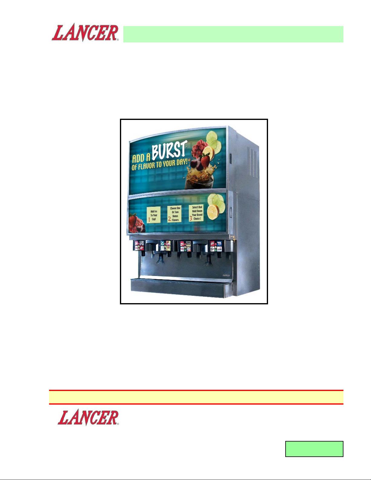
FOR THE FLAVORSELECT 44 (FS-44)
ICE BEVERAGE DISPENSER
LANCER SERIES 15800
This Manual is an initial issue.
Please refer to the Lancer web site (www.lancercorp.com) for information relating to Lancer
Installation and Service Manuals, Instruction Sheets, Technical Bulletins, Service Bulletins, etc.
DATE: 03/07/06
P.N. 28–0585
FAX Engineering: • 210-310-7096
"Lancer" is the registered trademark of Lancer • Copyright — 2006 by Lancer, all rights reserved
6655 LANCER BLVD. • SAN ANTONIO, TEXAS 78219 USA • (210) 310-7000
FAX SALES
• NORTH AMERICA – 210-310-7245 • INTERNATIONAL SALES – 210-310-7242 • CUSTOMER SERVICE – 210-310-7242 •
• LATIN AMERICA – 210-310-7245 • EUROPE – 32-2-755-2399 • PACIFIC – 61-8-8268-1978 •
85-15816-12-4-CN ICE BEVERAGE DISPENSER, ABOVE COUNTER MULTI BRAND, CUBE/PELLET ICE
44 INCH WIDE, 16 BRANDS / 4 FLAVORS, 115V/60Hz
85-15816-12-4-CC ICE BEVERAGE DISPENSER, ABOVE COUNTER MULTI BRAND, CUBE/CUBE ICE
44 INCH WIDE, 16 BRANDS / 4 FLAVORS, 115V/60Hz
85-15816-12-4-NN ICE BEVERAGE DISPENSER, ABOVE COUNTER MULTI BRAND, PELLET/PELLET ICE
44 INCH WIDE, 16 BRANDS / 4 FLAVORS, 115V/60Hz
Page 2
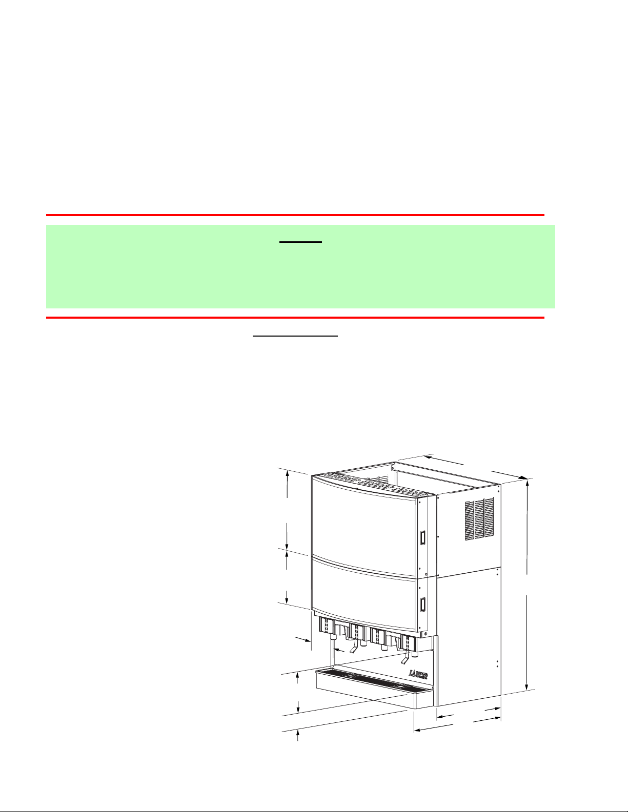
TABLE OF CONTENTS ......................................................................................................................................i
SPECIFICATIONS ...............................................................................................................................................i
1. INSTALLATION ...........................................................................................................................................1
1.1 COUNTER SELECTION ....................................................................................................................1
1.2 ELECTRICAL REQUIREMENTS .......................................................................................................1
1.3 DRAIN REQUIREMENTS ..................................................................................................................1
1.4 REQUIRED TOOLS FOR INSTALLATION ........................................................................................1
1.5 RECEIVING........................................................................................................................................1
1.6 UNPACKING ......................................................................................................................................2
2. ASSEMBLING THE DISPENSER ...............................................................................................................2
3. ILLUSTRATIONS AND PARTS LISTINGS ...............................................................................................12
3.1 MERCHANDISER KIT, FS-44 ..........................................................................................................12
3.2 COUNTER TEMPLATE, FS-44 ........................................................................................................14
i
NOTES:
The FS-44 Merchandising Unit contains one Merchandising Kit and two FS-22 Dispensers.
For information concerning the specifications, operation and service for the FS-22 dispensers in the
FS-44 unit, refer to Lancer Installation and Service Manual 28-0580, dated 01/18/06. This manual may
be found on the Lancer Web Site at www.lancercorp.com.
SPECIFICATIONS
DIMENSIONS
HEIGHT: 64.00 INCHES (1626 mm)
WIDTH: 46.75 INCHES (1187 mm)
DEPTH: 33.00 INCHES (838 mm)
COUNTER WEIGHT: (SEE SECTION 1.1.B)
SHIPPING WEIGHT: 250 LBS (113.4 KG)
(CLADDING KIT ONLY)
ELECTRICAL
VOLTAGE: 115
AMPS: 2.0
Hz: 60
24 1/4"
(616 mm)
46 3/4"
(1187 mm)
16"
(406 mm)
5 1/2"
(140 mm)
10"
(254 mm)
5 3/32"
(130 mm)
25 1/2"
(648 mm)
33"
(838 mm)
64"
(1626 mm)
Page 3
1
1. INSTALLATION
1.1 COUNTER SELECTION
A. Select a location close to properly grounded electrical outlets (see Section 1.2, Electrical
Requirements) and water supply that meet the requirements outlined below.
B. Counter location must be able to support a minimum of 1300 pounds (590 kg) per complete
FS-44 installation with Ice Makers installed.
C. An optional Counter cutout, if required for installation of unit, is shown in Section 3.1. A full size
template is provided with the FS-44 Installation Kit.
1.2 ELECTRICAL REQUIREMENTS
W
ARNING
ALL ELECTRICAL CIRCUITS MUST MEET LOCAL BUILDING CODES. EACH DRINK
DISPENSER MUST BE SUPPLIED WITH A SEPARATE ELECTRICAL CIRCUIT.
Each FS-22 dispenser must have an independent 115 Volt, 60 Hz, 20 Amp grounded circuit. The ice
dispenser should be connected per the manufacturer’s recommendations.
NOTE
An Ice Dispenser Installation Manual should be available from the manufacturer of the Ice Dispenser.
1.3 DRAIN REQUIREMENTS
Install Drip Tray and extend hose to open type drain.
1.4 REQUIRED TOOLS FOR INSTALLATION
The following tools will be required for installation:
A. Screw Driver, Phillips Head
B. Proper lifting equipment
1.5 RECEIVING
Each kit is thoroughly inspected before shipment. At time of shipment, the carrier accepts the unit(s)
and any claim for damages must be made with the carrier. Upon receiving unit(s) from the
delivering carrier, carefully inspect carton(s) for visible indication(s) of damage. If damage exists,
have carrier note same on bill of lading and file a claim with the carrier.
Photo 1
Photo 2
Page 4
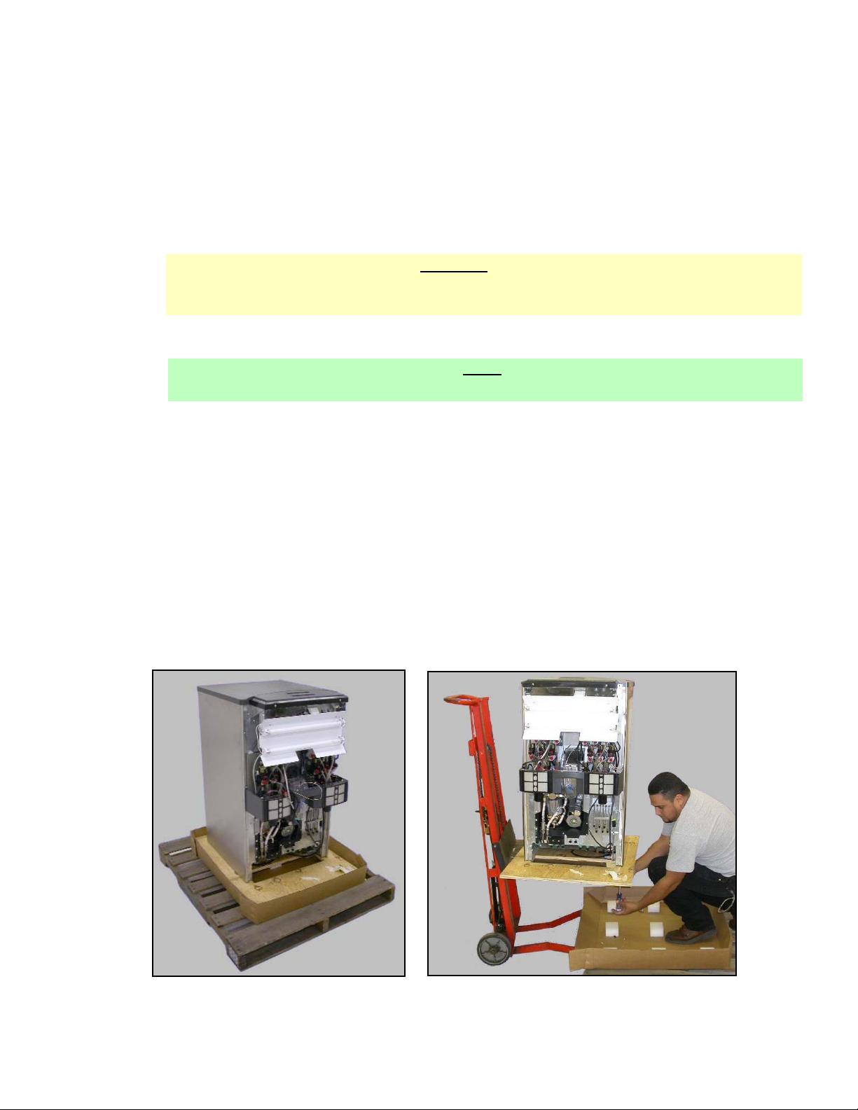
1.6 UNPACKING
A. Carefully cut band and remove.
B. Remove top portion of carton by lifting up.
C. Remove inserts.
D. Using proper lifting techniques, lift unit up by plywood shipping base, and remove lower portion
of carton.
E. Inspect unit for concealed damage (see Photo 1). If evident, notify delivering carrier and file a
claim against same.
F. Remove plywood shipping base from unit by locating unit so that one side is off the counter top
or table, allowing access to screws on the bottom of the plywood shipping base (see Photo 2).
NOTE
If unit is to be transported or moved to its installation location, it is advisable to leave unit
secured to plywood shipping base.
2
Photo 3
Locators
Photo 4
Photo 5
Photo 6
Use Screwdriver as
a temporary wedge
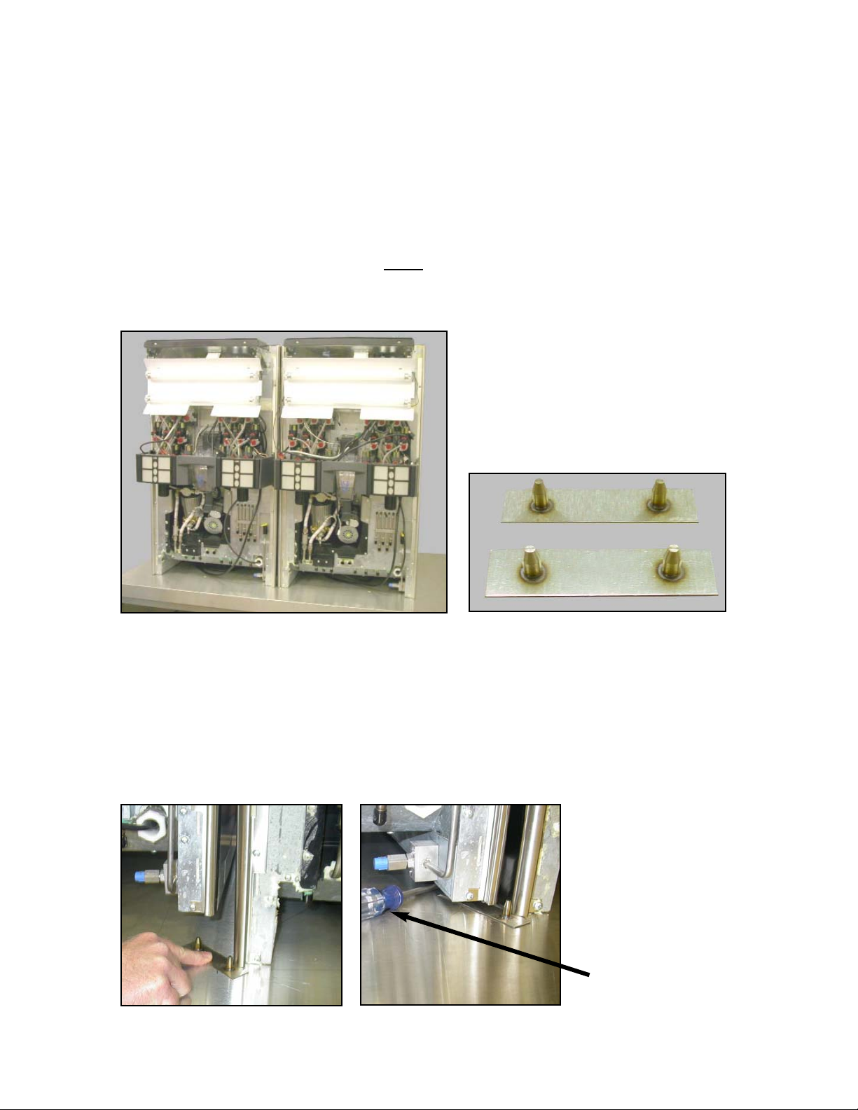
2. ASSEMBLING THE DISPENSER
STEP 1
A. Set both FS-22 dispensers on the counter. Align side-by-side and approximately one (1) inch
apart (see Photo 3).
B. Two locators (see Photo 4) will be installed: one at the front of the dispenser and one at the rear
of the dispenser. The prongs on the locators fit into the bottom of each machine when using the
existing threaded leg insert holes.
Page 5
3
1. Carefully tilt the first dispenser back to allow the insertion of the first prong into the hole (see
Photo 5).
2. Place a wedge under the dispenser so that the locator may be rotated, allowing the second
prong to fit into the existing hole. (see Photo 6).
3. When the locator is properly aligned under the two dispensers, remove the wedge.
C. Keeping the dispensers aligned, repeat Step B above at the rear of the dispenser.
STEP 4
A. At this point in the installation, do the dispenser set up, brix valves, etc. See Installation and
Service Manual, 28-0580, for procedures.
STEP 5
A. Install one inch drain tube to EACH DRAIN in the drip tray (see Photo 10) before installing the
drip tray to dispenser (two tubes are required). Route drain tubes to drain. Secure drip tray with
4 screws (see Photo 11).
Photo 8
Photo 7
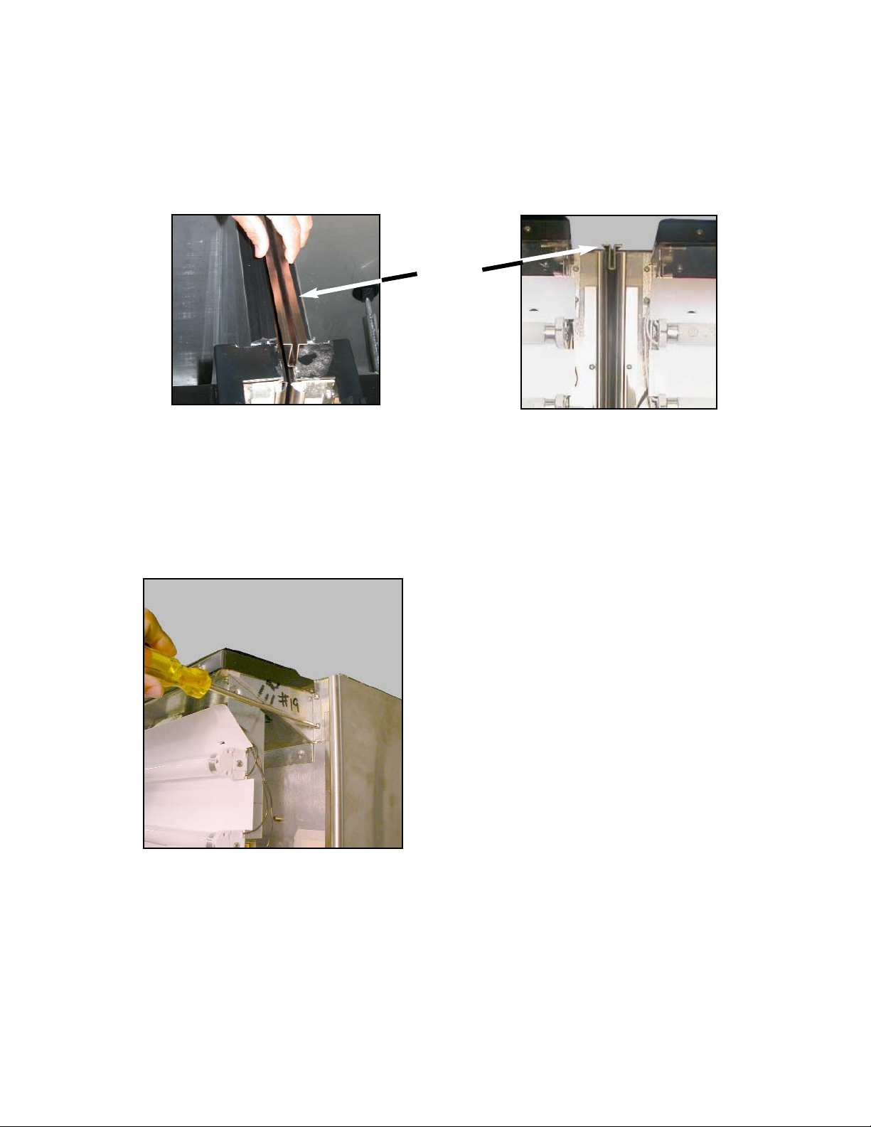
Separator
Rail
STEP 2
A. Carefully insert the unit separator rail at the top of the machine to keep the units properly aligned
and separated (see Photos 7 and 8). Use caution to avoid squeezing the separator rail shut.
STEP 3
A. Remove the four lower screws as shown in Photo 9. Retain these screws for reinstallation.
Photo 9
Page 6

4
NOTE:
Install ice makers to tops of FS 22 Dispensers BEFORE going to Step 6!
STEP 6
A. Install the T Gap filler between the two units as shown in Photo 12.
B. Install right side front sub frame to the dispenser. Reinstall one screw removed in Step 3A above
to secure the sub frame to the right side (see Photo 13).
C. Install left side front sub frame to the dispenser. Reinstall one screw removed in Step 3A above
to secure the sub frame to the left side.
D. Install middle front sub frame to the dispenser (see Photo 14). Secure with two screws removed
in Step 3A above.
Photo 13
Photo 14
Photo 15
STEP 7
A. Install the front, top rail, sub frame behind
the front sub frames installed in Step 4
(see Photo 15). Secure with four 8-24
screws provided in the installation kit.
Photo 11
Photo 10
Photo 12
Page 7

Photo 16
STEP 8
A. Install the left lower side panel by
attaching it to the sub frame (see
Photo 16). Secure with three 8-24
screws provided in the installation kit.
B. Install the right lower side panel by
attaching it to the sub frame. Secure
with three 8-24 screws provided in the
installation kit.
5
Lower left
side panel
Photo 17
Photo 18
Photo 20a
STEP 9
A. Install upper support rail to lower side panel (see Photo 17) and secure with four 8-24 screws
(two each end).
B. Install lower support rail to lower side panel (see Photo 18) and secure with four 8-24 screws
(two each end).
STEP 10
A. Hang upper light assembly on front top rail of sub frame (see Photos 19a and 19b).
B. Install two (2) screws to secure light assembly (see Photo 19c).
Photo 20c
Photo 20b
Page 8

6
STEP 11
A. Install lower merchandiser sub frame. Align tabs at top and bottom to grooves in the
merchandiser (see Photos 20a, 20b and 20c). When properly aligned, reinstall the four screws
and secure (see Photo 20d).
B. Connect the key switch harness to the key switch at each side of the lower merchandiser (see
Photo 21).
C. Hang upper sub frame to top rail (see Photos 22a and 22a2).
Photo 20b
Photo 20a
D. Install two (2) screws to upper merchandiser (see Photo 22b).
E. Install three fluorescent bulbs to light panel (see Photo 24).
Photo 20c
Photo 20d
Screw
Holes
Photo 21
Page 9

Photo 22b
Photo 22a2
7
Photo 22a
Photo 24
Photo 23
Page 10

STEP 13
A. Install the lower light reflector spacer, clipping it on (see Photos 27a and 27b).
B. Install upper and lower graphic merchandisers (see Photos 29a, 29b and 29c).
C. Assemble the Graphics panel (see Photo 28) and partially install to the lower merchandiser (see
Photo 31).
D. Install the Graphics panel to the lower merchandiser (see Photos 31 and 32).
8
Photo 25a
STEP 12
A. Install the left upper side panel by attaching it to the vertical support rail (see Photos 25a and
25b). Secure with three (3) 8-24 screws.
B. Install the right upper side panel by attaching it to the vertical support rail . Secure with three
(3) 8-24 screws.
Photo 25b
Light
Reflector
Spacer
In Place
Light
Reflector
Spacer
Photo 27a
Photo 27b
Page 11

Photo 28
Photo 29c
9
STEP 14
A. Connect the key switch harness in the
upper merchandiser (see Photo 33).
STEP 15
A. Assemble the Graphics panel and install to
the top merchandiser (see Photo 34).
Photo 29a
Photo 29b
Photo 30 Photo 31
Page 12

Photo 36
STEP 16
A. Install top and bottom end caps to upper and lower merchandisers (see Photo 35a, 35b and 35c)
to both the right and left sides. Secure with two screws per end cap piece. Adjust the end caps
to ensure no gap or seam is visible.
10
Photo 34
Photo 33
Photo 32
Photo 35a
Photo 35b
Photo 35c
Page 13

Photo 37
Photo 38
Photo 39
11
STEP 17
A. Install decorative end caps to right and left sides (see Photo 36) by snapping them into place.
B. Install splash plate (see Photo 37).
Page 14

12
3. ILLUSTRATIONS, PART LISTINGS, AND DIAGRAMS
3.1 MERCHANDISER KIT, FS-44
35
1
2
3
4
5
67
8
9
37
36
34
33
32
31
30
29
27,28
26
25
1011
12
13,14
15
16
17
18
19
20
21
24
23
22
Page 15

85-15816-12-4-CN IBD, ACMB, FS44,
2-22”, 16-12, CP
85-15816-12-4-CC IBD, ACMB, FS44,
2-22”, 16-12, CC
85-15816-12-4-NN IBD, ACMB, FS44,
2-22”, 16-12, PP
ITEM
P
ART NO. DESCRIPTION
1 30-9456 Panel, Top, Right, FS-44
2 04-0236 Screw, 10-24 x .375. PHD,
PH, MS, SS
3 82-3686 Reflector Assy, Top
Merchandiser, FS-44
4 30-9455 Brace, Rear, FS-44
5 30-9611 Frame, Right, FS-44
6 30-9457 Panel, Top, Left, FS-44
7 30-9460 Frame, Center, FS-44
8 30-9461 Angle, Frame, FS-44
9 30-9612 Frame, Left, FS-44
10 30-9615 Cap, End, Right, Top
Merchandiser, FS-44
11 51-6113 Weld Assy, Upper
Merchandiser Base, FS-44
12 30-9472 Support, Inner, Merchandiser,
FS-44
13 04-1486 Tinnerman, Speed Clip,
C1663-08
14 04-0072 Rivet, 0.125 DIA x 0.312, SS
15 30-9616 Cap, End, Left, Top
Merchandiser, FS-44
16 06-3002-01 xxxxx
17 30-9609 Panel, Right, Upper
Merchandiser, FS-44
18 30-9593 Cap, End, Left, Lower
Merchandiser, FS-44
ITEM PART NO. DESCRIPTION
19 30-9610 Panel, Left, Upper
Merchandiser, FS-44
20 06-3003-01 xxxxx
21 51-6113 Weld Assy, Lower
Merchandiser PF, FS-44
22 30-9464 Cover, Seam, Left, FS-44
-- 06-2930 Label, Configuration Diagram,
FS8
23 82-3602 Drip Tray Assy, FS-44
24 05-2455 Handle, Flush Pull, Snap Fit
25 30-9594 Cap, End, Right, Lower
Merchandiser, FS-44
26 30-9617 Plate, Splash, Ext, FS-44
27 04-1487 Tinnerman, Ball Stud,
P116-499
28 04-1006 Nut, KEPS, 6 - 32, 800/Delta
29 30-9463 Cover, Seam, Right, FS-44
30 30-9579 BTM, 57”, Upper
Merchandiser, FS-44
31 30-9462 Plate, Dresser, Center, FS-44
32 30-9622 Bracket, Support, Top
Merchandiser, FS-44
33 51-6085 Plate Assy, Connector,
Bottom, FS-44
34 30-9507 Panel, Reflector, Spacer,
FS-44
35 51-6114 Weld Assy, Lower
Merchandiser Base, FS-44
36 30-9628 Panel, Left, FS-44
37 51-5361 Channel, Lid, Double 22”, IBD
3.1 MERCHANDISER KIT, FS-44 (CONTINUED)
13
Page 16

3.2 COUNTER TEMPLATE
14
8.500
3.500
16.000
44.750
R.625
6.500
OUTLINE OF FS-8 (QUANTITY 2) NOT FS-44 CLADDING
16.000
TEMPLATE FOR COUNTER TOP CUTOUT FOR
FS-44 CLADDING AND MERCHANDISER KIT
23.125
 Loading...