

Page 1

Ice Cooled Dispener 1523 Series 2200
Operation Manual
PN: 28-0086/03
MODEL NO.
Lancer Corp.
6655 Lancer Blvd.
San Antonio, Texas 78219
800-729-1500
Technical Support/Warranty: 800-729-1550
custserv@lancercorp.com
lancercorp.com
Manual PN: 28-0086/03
11/03/97
FOR QUALIFIED INSTALLER ONLY
“Lancer” is the registered trademark of Lancer © 2014 by Lancer, all rights reserved.
Page 2

ABOUT THIS MANUAL
This booklet is an integral and essential part of the product and should be handed over to the operator after the installation and preserved for any further consultation that may be necessary. Please read carefully the guidelines and warnings contained herein as they are intended to provide the user with essential information for the continued safe use
and maintenance of the product. In addition, it provides GUIDANCE ONLY to the user on the correct services and site
location of the unit.
The installation and relocation, if necessary, of this product must be carried out by qualied personnel with up-to-date
safety and hygiene knowledge and practical experience, in accordance with current regulations.
TABLE OF CONTENTS
SPECIFICATIONS................................................................................................................................3
PRE-INTALLATION CHECKLIST........................................................................................................4
WARNINGS/CAUTIONS...................................................................................................................5-8
1. INSTALLATION OF LANCER ICE COOLED DISPENSER..........................................................9
1.1 UNPACKING.........................................................................................................................9
1.2 SELECT A COUNTER LOCATION.......................................................................................9
1.3 WATER SUPPLY...................................................................................................................9
1.4 ELECTRICAL SUPPLY........................................................................................................10
1.5 SYRUP CONTAINERS.......................................................................................................10
1.6 INSTALLATION OF THE UNIT............................................................................................10
1.7 CONNECTION OF THE UNIT.............................................................................................11
1.8 START UP......................................................................................................................11-12
1.9 ADJUSTING WATER FLOW...............................................................................................12
1.10 ADJUSTING WATER-TO-SYRUP RATIO (BRIX)...............................................................12
1.11 REPLENISHING SYRUP SUPPLY (5 GALLON TANKS)....................................................13
2. RECOMMENDED SERVICE AND MAINTENANCE...................................................................13
2.1 SCHEDULED......................................................................................................................13
2.2 CLEANING AND SANITIZING SYSTEMS.....................................................................13-14
2.3 CLEANING AND SANITIZING FIGAL SYSTEMS..........................................................14-15
2.4 CELANING AND SANITIZING BAG-IN-BOX (BIB) SYSTEMS.....................................15-16
2.5 VALVES...............................................................................................................................16
2.6 ICE BIN COMPARTMENT ON ALL ICE CHESTS..............................................................16
3. TROUBLESHOOTING................................................................................................................17
4. DISPENSER DISPOSAL.............................................................................................................17
5. ILLUSTRATIONS, PARTS LISTINGS, AND WIRING DIAGRAMS............................................19
5.1 LANCER ICE COOLED DISPENSER -- ACCESSORIES..................................................19
5.2 SERIES 1500 DROP-IN (PRE-MIX)..............................................................................20-21
5.3 SERIES 1500 DROP-IN................................................................................................22-23
5.4 SERIES 1500 PLUG-IN DROP-IN SABRE....................................................................24-25
5.5 ICE COOLED UNIVERSAL WIRING DIAGRAM WITH BIN LID SWITCH.........................26
5.6 ICE COOLED UNIVERSAL WIRING DIAGRAM WITHOUT BIN LID SWITCH..................27
2
Page 3
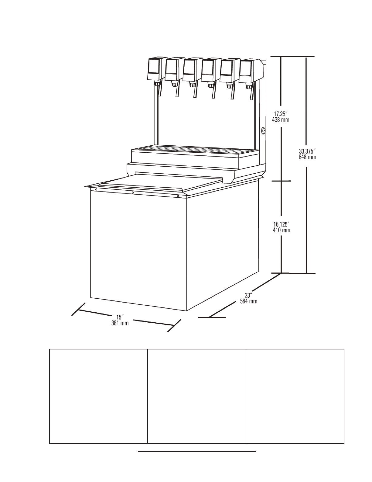
ICD 1523 SPECIFICATIONS
DIMENSIONS
Width: 15 inches (381 mm)
Depth: 23 inches (584 mm)
Height: 33.375 inches (848 mm)
COUNTER CUT-OUT
Width: 15.25 inches (387 mm)
Depth: 23.25 inches (591 mm)
ELECTRICAL
115 VAC/ 60 Hz
WEIGHT
Operating: 166 lbs (75 kg)
Shipping: 130 lbs (59 kg)
ICE
Capacity: 60 lbs (27.2 kg)
FITTINGS
Soda water inlet: 3/8” barb
Brand syrup inlets: 3/8” barb
This unit emits a sound pressure level below 70 dB
3
PLAIN WATER SUPPLY
Min owing pressure:
20 PSI (0.138 MPA)
Max owing pressure:
50 PSI (0.345 MPA)
CARBON DIOXIDE (CO2)
Min pressure:
90 PSIG (0.621 MPA)
Max pressure:
110 PSIG (0.758 MPA)
Page 4
PRE-INSTALLATION CHECKLIST
BEFORE GETTING STARTED
Each unit is tested under operating conditions and is thoroughly inspected before
shipment. At the time of shipment, the carrier accepts responsibility for the unit. Upon receiving the unit, carefully inspect the carton for visible damage. If damage exists, have the carrier note the damage on the freight bill and le a claim with carrier. Responsibility for damage to the dispenser lies with the carrier.
TOOLS REQUIRED
Oetiker Pliers Slotted Screwdriver
Tubing Cutters Phillips Screwdriver
Wrench Cordless Drill
POST MIX ACCESSORIES
CO2 Regulator Set CO2 Supply
Beverage Tubing Oetiker Clamps/Fittings
Water Booster Water Regulator
Precision Cutters (if removing/replacing carbonator tank)
BIB SYSTEM
BIB Rack BIB Regulator Set
BIB Syrup Boxes
BIB Connectors - ensure you have the correct connectors for syrup lineup.
CONSIDER LOCATION OF THE FOLLOWING PRIOR TO INSTALL
Water supply lines Drain
Is the countertop level? Heating and air conditioning ducts
Grounded electrical outlet.
Enough space to install the dispenser. Include space for a top-mounted ice machine, if necessary.
Does the top-mounted ice machine have a minimum clearance on all sides?
Located away from direct sunlight or overhead lighting.
Can the countertop support the weight of the dispenser? Be sure to include the weight of an ice
machine (if necessary) plus the weight of the ice.
This unit is not suitable for use in an area where a water jet could be used.
4
Page 5

! !
WARNING/ADVERTENCIA/AVERTISSEMENT
!
The dispenser is for indoor use only. This unit is not a toy. Children should not be supervised not to play with
appliance. It should not be used by children or inrm persons without supervision. This appliance is not intended
for use by persons (including children) with reduced physical, sensory or mental capabilities, or lack of experience
and knowledge, unless they have been given supervision or instruction concerning use of the appliance by a person
responsible for their safety. Cleaning and user maintenance shall not be performed by children without supervision.
This unit is not designed to dispense dairy products. The min/max ambient operating temperature for the dispenser is
40°F to 90°F (4°C to 32°C). Do not operate unit below minimum ambient operation conditions. Should freezing occur,
cease operation of the unit and contact authorized service technician. Service, cleaning and sanitizing should be accomplished only by trained personnel. Applicable safety precautions must be observed. Instruction w!arnings on the
product being used must be followed.
! El dispensador sólo debe usarse en interiores. Esta unidad no es un juguete. Los niños deben ser supervisados
para no jugar con aparato. No la deben usar niños ni personas discapacitadas sin supervisión. Esta unidad no está
destinada al uso por parte de personas (incluso niños) con capacidad física, sensorial o mental reducida, o sin experiencia y conocimientos sucientes, a menos que una persona responsable de su seguridad les haya dado supervisión o capacitación en el uso de la unidad. Limpieza y mantenimiento de usuario no deberá ser realizada por los
niños sin supervisión. Esta unidad no ha sido diseñada para suministrar productos lácteos. La temperatura ambiente
operativa mínima / máxima para el dispensador es de 40°F a 90°F (4°C a 32°C). No opere la unidad debajo de las
condiciones de funcionamiento ambientales mínimos. En caso de congelación se produce, cesar la operación de la
unidad y el contacto técnico de servicio autorizado. Servicio de limpieza y desinfección deben llevarse a cabo solamente por personal capacitado. Es necesario tomar medidas de seguridad aplicables. Advertencias de las instrucciones sobre el producto utilizado se deben seguir.
! Le distributeur est destiné à un usage à l’intérieur seulement. Cet appareil n’est pas un jouet. Les enfants doivent
être surveillés an de ne pas jouer avec l’appareil. Il ne devrait pas être utilisé par des enfants ou des personnes
inrmes sans surveillance. Cet appareil n’est pas destiné à un usage par des personnes (y compris les enfants)
ayant des capacités physiques, sensorielles ou mentales réduites, ou manquant d’expérience et de connaissances,
à moins qu’elles obtiennent de la surveillance ou des instructions au sujet de l’utilisation de l’appareil de la part d’une
personne chargée de leur sécurité. Nettoyage et entretien de l’utilisateur ne doivent pas être effectués par des enfants sans surveillance. Cet appareil n’est pas conçu pour distribuer des produits laitiers. La température de service
ambiante minimum/maximum pour le distributeur est de 40°F à 90°F (4°C à 32°C). Ne pas utiliser l’appareil dans des
conditions de performance environnementale minimale. En cas de gel, cesser l’exploitation de l’unité et contactez un
technicien agréé. Nettoyage et désinfection doivent être effectuées uniquement par du personnel qualié. Vous devez
prendre des mesures de sécurité. Avertissements instructions sur le produit utilisé doivent être respectées.
5
Page 6
!
This unit has been factory sanitized per Lancer specications.
Listed below are six critical elements which will aid in a successful installation.
1. Fill water bath until water overows from tank overow tube.
2. The carbonator pump motor must be disconnected from the power supply prior to connection to water supply for
initial build up of ice bank. Failure to do so will result in automatic shut off of carbonator (see item 6 below) or damage
to the pump.
3. If this dispenser is installed in an area that is susceptible to ±10% variation of the nominal line voltage, consider
installing a surge protector or similar protection device.
4. There is a ve (5) minute delay which prevents the compressor and condenser fan from starting until the delay
has lapsed. If electrical current is interrupted, there is always a ve (5) minute delay before the compressor starts.
5. Supply Water Pressure: Minimum - 20 PSI (0.138 MPA); Maximum - 50 PSI (0.345 MPA); If pressure is over 50
PSIG (0.345 MPA), a water pressure regulator must be used.
6. On units with the built in water regulator, the regulator must be removed if inlet water pressure is less than 20
PSIG. (0.138 MPA)
DISPENSER INSTALLATION HIGHLIGHTS
!
!
Esta unidad ha sido saneada en fabrica por las especicaciones de Lancer.
A continuacion se relacionan 6 puntos importantes para una connecta instalacion.
1. Llene el bano-Maria hasta que el agua se desborde sobre el tubo que controla la derrama del tanque.
2. El motor de la bomba del carbonatador debe desconectarse electricamente antes de conectar el suministro de
agua para la formacion inicial del banco de hielo. De no hacerse esto resultaria en un bloqueo automatico del
carbonatador (ver abajo el punto 6) o en danos a la bomba.
3. Si la unidad va a ser instalada en un area en la que puedan darse variaciones de voltage de + 6 - 10% de su
valor nominal, se debe considerar la conveniencia de instalar un estabilizador de corriente o sistema de proteccion
similar.
4. Hay una demora de 5 minutos que evita que el compresor y el abanico del condensador arranquen hasta pasado
ese tiempo. Si hay algun corte en la corriente electrica siempre se producira esa demora de 5 minutos antes de arrancar el compresor.
5. Presión de suministro del agua de red: Minimo 20 PSI (0.138 MPA); Maximo 50 PSI (0.345 MPA). En unidades
sin regulador de presión incorporado, si la presión del agua es superior a 50 PSIG (0.345 MPA) se debe usar un
regulador de presión.
6. En unidades con regulador de presión incorporado, el regulador debe der eliminado cuando la presión de entrada
de agua sea inferior a 20 PSIG (0.138 MPA).
!
REGLES DE SECURITE POUR L’NSTALLATION DU DISTRIBUTEUR DE SODAS
PUNTOS IMPORTANTES EN LA UNIDAD DISPENSADORA
!
!
La proprètè da cet ensamable est assurè à I’usine sulvant les spècications èmis par Lancer .
Il est essentiel de respecter les 6 points suivants pour l’installation de l’appareil:
1. Remplir le bain-Maire jusqu’a ce que l’eau dèborde par le tuyau de trop-plein du rèservoir.
2. Le moteur de la pompe du carbonateur doit etre dèbranchè de l’alimentation èlectrique avant l’arrivèe de l’eau
pour la formation initiale de la glace. Oublier ou nègliger cette opèration provoquera l’arret automatique du
carbonateur (voir le point 6 cidessous) ou causera des dommages à la pompe.
3. Si le distributeur es installè dans une zone ou la tension èlectrique nominale est susceptible de variations de (+)
10%, il est conseillè d’installer un appaeil de protection contre les sautes de courant.
4. Un d’lai de 5 minutes empeche le compresseur et la ventilation du condesateur de se mettre en marche avant
que ce lees de temps ne se soit ècoulè. Lorsque le courant èlectrique es interrompu, il y a toujours un dèlai de 5
minutes avant que le presseur ne se mette en.
5. Pression de l’eau: Minimum 20 PSI (0.138 MPA); Maximo 50 PSI (0.345 MPA). Sur les unitès qui n’ont pas de
règulateur de pression d’eau incorprè, si la pression d’H2O est supèrieure à 50 PSIG (0.345 MPA), un règulateur de
pression d’eau doit etre utilsisè.
6. Sur les unitès avec règulateur d’eau incorporè, le règulateur doit etre enlevè si la pression d’arrivve est inferièure
à 20 PSIG (0.138 MPA)
6
Page 7
ELECTRICAL WARNING/ADVERTENCIA ELÉCTRICA/
F F
F
Check the dispenser serial number plate for correct electrical requirements of unit. Do not plug into a wall
electrical outlet unless the current shown on the serial number plate agrees with local current available. Follow
all local electrical codes when making connections. Each dispenser must have a separate electrical circuit. Do not
use extension cords with this unit. Do not ‘gang’ together with other electrical devices on the same outlet. The
keyswitch does not disable the line voltage to the transformer primary. Always disconnect electrical power to the unit
to prevent personal injury before attempting any internal maintenance. The resettable breaker switch should not
be used as a substitute for unplugging the dispenser from the power source to service the unit. Only qualied
personnel should service internal components of electrical control housing. Make sure that all water lines are
tight and units are dry before making any electrical connections!
AVERTISSEMENT ÉLECTRIQUE
F Verique la placa con el número de serie del dispensador, donde encontrará los requisitos eléctricos correctos
de la unidad. No enchufe la unidad en un tomacorriente de pared a menos que la corriente indicada en la placa con
el número de serie concuerde con la corriente local disponible. Al hacer las conexiones, respete todos los códigos
eléctricos locales. Cada dispensador debe tener un circuito eléctrico independiente. No use extensiones con esta
unidad. No la conecte junto con otros dispositivos eléctricos al mismo tomacorriente. El interruptor de llave no corta
el voltaje de línea al transformador primario desconecte siempre la alimentación eléctrica a la unidad para evitar
lesiones personales antes de tratar de realizar tareas de mantenimiento. El disyuntor de sobrecarga
reseteable no se debe usar como sustituto para desenchufar el dispensador de la fuente de alimentación para
realizar tareas de servicio de la unidad. El servicio de los componentes internos de la caja de control eléctrico debe
conarse exclusivamente a personal calicado. Asegúrese de que todas las líneas de agua estén ajustadas y las
unidades estén secas antes de hacer conexiones eléctricas.
F Examinez la plaque de numéro de série du distributeur pour connaître les bonnes exigences en matière
d’électricité pour l’appareil. Ne le branchez pas à une prise électrique murale à moins que le courant indiqué sur la
plaque de numéro de série corresponde au courant local disponible. Respectez tous les codes électriques locaux
lorsque vous faites des connexions. Chaque distributrice doit avoir un circuit électrique séparé. N’utilisez pas
de cordons prolongateurs avec cet appareil. Ne pas le brancher avec d’autres appareils électriques sur la même
prise. L’interrupteur à clé ne coupe pas la tension secteur au transformateur primaire. Débranchez toujours le courant
électrique à l’appareil, an de prévenir des blessures, avant de faire un entretien interne quelconque. Le disjoncteur
réarmable ne devrait pas être utilisé au lieu de débrancher le distributeur de la source d’alimentation en électricité
pour faire de l’entretien/une réparation de l’appareil. Seul le personnel qualié devrait faire l’entretien/la réparation
des composants internes dans le logement des commandes électriques. Assurez-vous que toutes les conduites
d’eau sont étanches et que les appareils sont secs avant de faire des connexions électriques!
CO2/CARBON DIOXIDE /El ANHÍDRIDO CARBÓNICO/
5 5
5
Carbon Dioxide (CO2) is a colorless, noncombustible gas with a light pungent odor. High percentages of CO2 may
displace oxygen in the blood. Prolonged exposure to CO2 can be harmful. Personnel exposed to high concentrations
of CO2 gas will experience tremors which are followed by a loss of consciousness and suffocation. If a CO2 gas leak
is suspected, immediately ventilate the contaminated area before attempting to repair the leak. Strict attention must
be observed in the prevention of CO2 gas leaks in the entire CO2 and soft drink system.
DIOXYDE DE CARBONE
5 El anhídrido carbónico (CO2) es un gas incoloro, no combustible, con un olor pungente ligero. Altos porcentajes
de CO2 en la sangre pueden desplazar el oxígeno en la sangre. La exposición prolongada al CO2 puede ser nociva.
El personal expuesto a concentraciones altas de CO2 sufre temblores seguidos de la pérdida de la consciencia y
sofocación. Si se sospecha que existe una pérdida de CO2, ventile el área contaminada antes de tratar de reparar
la pérdida. Hay que prestar suma atención para evitar pérdidas de CO2 en todo el sistema de CO2 y de bebidas
gaseosas.
5 Le dioxyde de carbone (CO2) est plus lourd que l’air et déplace l'oxygène. Le CO2 est un gaz incolore et incom-
bustible, ayant une odeur un peu âcre. Des concentrations fortes de CO2 peuvent déplacer l'oxygène dans le sang.
Une exposition prolongée au CO2 peut être nocive. Le personnel exposé à de fortes concentrations de CO2 gazeux
éprouvera des tremblements, suivis rapidement d'une perte de conscience et de suffocation. On doit faire très attention de prévenir les fuites de CO2 gazeux dans le système entier de CO2 et de boisson gazeuse. Si on suspecte qu'il
y a une fuite de CO2 gazeux, aérez le secteur contaminé immédiatement avant d'essayer de réparer la fuite.
7
Page 8
AUTOMATIC AGITATION/AGITACIÓN AUTOMÁTICA/
! Units are equipped with an automatic agitation system and will activate unexpectedly. Do not place hands or for-
eign objects in the water bath tank. Unplug the dispenser during servicing, cleaning, and sanitizing. To avoid personal
injury, do not attempt to lift the dispenser without assistance. For heavier dispensers, use a mechanical lift.
! Las unidades están equipadas con un sistema automático de agitación, por lo que se pueden activar repentina-
mente. No ponga las manos ni objetos extraños en el compartimiento donde se guarda el hielo. Durante el servicio,
la limpieza y la esterilización, desenchufe el dispensador. Para evitar lesiones personales, no trate de levantar el
dispensador sin ayuda. Para los dispensadores más pesados, use un elevador mecánico.
! Les appareils sont équipés d’un système d’agitation automatique qui s’activera de manière inattendue. Ne mettez
pas les mains ou des corps étrangers dans le compartiment d’entreposage de glace. Débranchez le distributeur
pendant l’entretien/la réparation, le nettoyage et l’aseptisation. Pour éviter des blessures, n’essayez pas de soulever
le distributeur sans aide. Pour les distributeurs plus lourds, utilisez un chariot élévateur.
! !
WATER NOTICE/AGUA AVISO/ PRÉAVIS DE L’EAU
!
Provide an adequate potable water supply. Water pipe connections and xtures directly connected to a potable
water supply must be sized, installed, and maintained according to federal, state, and local laws. The water
supply line must be at least a 3/8 inches (9.525 mm) pipe with a minimum of 20 PSI (0.138 MPA) line pressure, but
not exceeding a maximum of 50 PSI (0.345 MPA). Water pressure exceeding 50 PSI (0.345 MPA) must be reduced
to 20 PSI (0.138 MPA) with the provided pressure regulator. Use a lter in the water line to avoid equipment damage
and beverage off-taste. Check the water lter periodically, as required by local conditions. The water supply must be
protected by means of an air gap, a backow prevention device (located upstream of the CO2 injection system) or
another approved method to comply with NSF standards. A leaking inlet water check valve will allow carbonated
water to ow back through the pump when it is shut off and contaminate the water supply. Ensure the backow prevention device complies with ASSE and local standards. It is the responsibility of the installer to ensure compliance.
! Proporcione un suministro adecuado de agua potable. La línea de suministro de agua debe ser de una tubería de
por lo menos 3/8 pulgadas (9.525 mm) con una presión de línea mínima de 20 PSI (0.138 MPA) , pero sin superar
el máximo de 50 PSI (0.345 MPA). La presión de agua que supere los 50 PSI (0.345 MPA) se debe reducir a 20 PSI
(0.138 MPA) con un regulador de presión. Use un ltro en la línea de agua para evitar daños al equipo y cierto sabor
raro en las bebidas. Verique periódicamente el ltro de agua de acuerdo con las condiciones imperantes. El
suministro de agua debe estar protegido por una separación de aire, un dispositivo de prevención del contraujo
(situado antes del sistema de inyección de CO2) u otro método aprobado para cumplir las normas NSF. Si la válvula
de retención de entrada de agua tuviera pérdidas, permitiría el contraujo del agua carbonatada a través de la
bomba cuando se la detiene y contaminaría el suministro de agua. Asegúrese de que el dispositivo de prevención del
contraujo cumpla con las normas locales y de ASSE. Es responsabilidad del instalador cumplir con estos requisitos.
! Fournissez une alimentation en eau potable adéquate. Les connexions et les dispositifs de conduite d’eau
con- nectés directement à une alimentation en eau potable doivent être calibrés, installés et maintenus selon les lois
fédérales, provinciales et locales. La conduite d’alimentation en eau doit être un tuyau d’au moins 3/8 pouces (9.525
millimètres) avec une pression de ligne minimum de 20 LPC (0.138 MPA) , mais ne doit pas dépasser un maximum
de 50 LPC (0.345 MPA). Une pression d’eau de plus de 50 LPC (0.345 MPA) doit être réduite à 20 LPC (0.138
MPA) avec le régu- lateur de pression fourni. Utilisez un ltre dans la conduite d’eau pour éviter des dommages à
l’équipement et un goût des boissons qui n’est pas juste. Vériez le ltre à eau périodiquement, selon les exigences
des conditions locales. L’alimentation en eau doit être protégée au moyen d’un intervalle d’air, un disconnecteur
hydraulique (situé en amont du système d’injection de CO2) ou une autre méthode approuvée pour se conformer
aux normes de la NSF. Un clapet antiretour pour l’eau entrante qui fuie permettra à l’eau gazeuse de repasser par
la pompe quand elle est fermée et de contaminer l’alimentation en eau. Assurez-vous que le disjoncteur hydraulique
soit conforme aux normes de l’ASSE et locales. L’installateur est responsable d’assurer la conformité.
8
Page 9

1. INSTALLATION OF LANCER ICE COOLED DISPENSER
1.1 UNPACKING
A. The Lancer Ice Cooled Dispenser is shipped in a corrugated shipping carton.
B. Carefully remove the corrugated shipping carton from the unit.
C. Remove parts from the Ice Compartment.
D. Inspect unit for concealed damage(s). If evident, notify delivering carrier and le a claim against
same.
1.2 SELECTING A COUNTER LOCATION
A. Select a counter location which is close to a properly grounded electrical outlet, and a water
supply that meets the requirements specied in Section 1.4 below.
B. Counter location must be able to safely support a minimum of 225 pounds (102.3 kg) after
counter cutout is made.
1.3 WATER SUPPLY
CAUTION FAILURE TO LIMIT WATER PRESSURE TO 50 PSI (0.345 MPA) WILL RESULT IN IMPROPER
PERFORMANCE OF THE DISPENSER.
PRECAUCIÓN FALTA DE LIMITAR LA PRESIÓN DE AGUA PARA 50 PSI (0.345 MPA) DARÁ LUGAR A LA MALA
EJECUCIÓN DEL DISPENSADOR.
!
ATTENTION DÉFAUT DE LIMITER LA PRESSION DE L’EAU A 50 PSI (0,345 MPA) ENTRAÎNERA LA MAUVAISE
EXÉCUTION DU DISTRIBUTEUR.
A. An adequate potable water supply must be provided. The water supply line must be at least a
3/8 inch pipe with a minimum of 20 PSI (0.138 MPA) line pressure, but not exceeding a
maximum of 50 PSI (0.345 MPA). Water pressure exceeding 50 PSI (0.345 MPA) must be
reduced to 50 PSI 0.345 MPA) with a pressure regulator.
CAUTION A FILTER IN THE WATER LINE MUST BE USED IF THE WATER SUPPLY CONTAINS ANY APPRECIABLE
AMOUNT OF SILT, SAND, OR ANY OTHER DEBRIS. FAILURE TO DO SO CAN RESULT IN EQUIPMENT DAMAGE.
PRECAUCIÓN UN FILTRO EN LA TUBERÍA DE AGUA DEBE SER USADO SI EL SUMINISTRO DE AGUA CONTIENE
UNA CANTIDAD APRECIABLE DE CIENO, ARENA, CUALQUIER OTRO DESPERDICIO. NO HACERLO PUEDE
PROVOCAR DAÑOS AL EQUIPO.
!
ATTENTION UN FILTRE DANS LA CONDUITE D’EAU DOIT ÊTRE UTILISÉE SI L’APPROVISIONNEMENT EN EAU
CONTIENT UNE QUANTITÉ APPRÉCIABLE DE LIMON, DE SABLE, OU TOUTE AUTRE DÉBRIS. PANNE DE LE
FAIRE PEUT PROVOQUER DES DOMMAGES MATÉRIELS..
B. The Carbonator Pump is equipped with a Strainer and a Tee on the outlet side for a plain water
Valve (if required), but a water supply containing any appreciable quantity of silt, ne sand, or
other debris requires a Filter ahead of the Unit. The Filter cartridge must be cleaned
periodically, depending upon the condition of the water. Failure to do so may starve the Pump
and cause it to burn out; thereby, voiding the equipment warranty
9
Page 10

1.4 ELECTRICAL SUPPLY
GROUNDING WARNING THE DISPENSER MUST BE PROPERLY ELECTRICALLY GROUNDED TO AVOID
SERIOUS INJURY OR FATAL ELECTRICAL SHOCK. THE POWER CORD HAS A THREE-PRONG GROUNDED
PLUG. IF A THREE-HOLE GROUNDED ELECTRICAL OUTLET IS NOT AVAILABLE, USE AN APPROVED METHOD TO
GROUND THE UNIT. FOLLOW ALL LOCAL ELECTRICAL CODES WHEN MAKING CONNECTIONS. EACH
DISPENSER MUST HAVE A SEPARATE ELECTRICAL CIRCUIT. DO NOT USE EXTENSION CORDS. DO NOT
CONNECT MULTIPLE ELECTRICAL DEVICES ON THE SAME OUTLET.
ADVERTENCIA, PUESTA A TIERRA ES NECESARIO PONER A TIERRA ELÉCTRICAMENTE EL
DISPENSADOR PARA EVITAR LESIONES GRAVES E INCLUSO ELECTROCHOQUES FATALES. EL CABLE DE
ALIMENTACIÓN TIENE UN ENCHUFE PUESTO A TIERRA DE 3 CLAVIJAS. SI NO SE DISPONE DE UN TOMA
ELÉCTRICO CONECTADO A TIERRA DE TRES AGUJEROS, USE UN MÉTODO APROBADO PARA PONER A TIERRA
LA UNIDAD. AL HACER LAS CONEXIONES, RESPETE TODOS LOS CÓDIGOS ELÉCTRICOS LOCALES. CADA
F
DISPENSADOR DEBE TENER UN CIRCUITO ELÉCTRICO INDEPENDIENTE. NO USE CABLES DE EXTENSIÓN. NO
CONECTE VARIOS DISPOSITIVOS ELÉCTRICOS AL MISMO TOMACORRIENTE.
EXIGENCES DE MISE À LA TERRE LA DISTRIBUTRICE DOIT ÊTRE MISE À LA TERRE ÉLECTRIQUEMENT
CORRECTEMENT POUR ÉVITER DES BLESSURES GRAVES OU UNE DÉCHARGE ÉLECTRIQUE MORTELLE. LE
CORDON D’ALIMENTATION A UNE FICHE À TROIS BRANCHES MISE À LA TERRE. SI AUCUNE PRISE DE
COURANT ÉLECTRIQUE À TROIS TROUS N’EST DISPONIBLE, UTILISEZ UNE MÉTHODE APPROUVÉE POUR
METTRE L’UNITÉ À LA TERRE. RESPECTEZ TOUS LES CODES ÉLECTRIQUES LOCAUX LORSQUE VOUS FAITES
DES CONNEXIONS. CHAQUE DISTRIBUTRICE DOIT AVOIR UN CIRCUIT ÉLECTRIQUE SÉPARÉ. N’UTILISEZ PAS
DE CORDONS PROLONGATEURS. NE BRANCHEZ PAS PLUSIEURS APPAREILS ÉLECTRIQUES À LA MÊME PRISE
DE COURANT.
A. A standard 15 AMP, 110 VAC, 60 Hz, single phase electrical power outlet with a ground
connector should be provided for the operation of the unit
1.5 SYRUP CONTAINERS
A. When the unit is used in the Coca-Cola Company installations, the syrup containers are to be
attached as outlined in the appropriate Coca-Cola Company Service Manual.
B. For other installations, the syrup containers (sold as an accessory) are of stainless steel
construction with a capacity of ve gallons. They are equipped with a CO2 gas quick disconnect
tting and a syrup quick disconnect tting. The standard syrup outlet is a 1/4 inch (6.35 mm)
male are (MF). A low pressure regulator manifold (an accessory) may be mounted on the wall
above the syrup tanks.
C. The inlets on the unit, located on the right rear of the machine, are tagged (or coded) to the
proper valves. When making the connection to these inlets, provide a good, leak tight joint to
prevent twisting the tubing.
1.6 INSTALLATION OF THE UNIT
A. Inspect the counter location where the unit is to be installed. Verify that the counter is strong
enough to safely support a 225 pound (102.3 kg) load, after the cutout for the unit is made.
B. Verify that the unit will t in the desired location. See Figure 1 for the footprint and counter
cutout for the unit.
NOTE: Remember that the unit can extend up to 23 inches (58.42 cm) below the counter, including
the shipping risers, which Lancer recommends be left attached to the unit. Should the dispenser
ever require removal, the shipping risers will protect the inlet tubes from being damaged.
C. After the counter cutout is complete, the unit may be lowered into the counter.
(CUTOUT)
FRONT
17"
(43.18 cm)
23 1/4" (59.06 cm)
(CUTOUT)
15 1/4"
(38.74 cm)
NOTES:
Solid lines
represent counter
cutout dimensions.
Dashed lines
represent the counter
footprint of the ice
bin flange.
25" (63.50 cm)
SIDE
(View Looking Down)
10
Counter Cutout for Dispenser
FIGURE 1
Page 11

1.7 CONNECTION OF THE UNIT
A. Position the CO2 gas tank in the desired location. Assemble the high pressure regulator to the
CO2 gas tank and run jumper line to low pressure regulator.
B. Attach the CO2 gas line to the carbonator by attaching the line from the high pressure regulator
to the single check valve marked “gas” on top of the Carbonator Tank. The setting of the high
pressure CO2 gas Regulator should be 90 PSI (0.621 MPA) to 110 PSI (0.758 MPA).
WARNING DO NOT TURN ON THE CO2 SUPPLY AT THIS TIME.
ADVERTENCIA NO CONECTE TODAVÍA LA ALIMENTACIÓN DE CO2.
5
C. Position the syrup tanks in the desired location. Attach the CO2 gas lines leading from the low
pressure regulator to these tanks.
D. Connect syrup lines from tanks to the appropriate inlets at the right front of the unit. The syrup
inlets are identied.
AVERTISSEMENT N’OUVREZ PAS L’ALIMENTATION EN CO2 À CE MOMENT.
CAUTION A FILTER IN THE WATER LINE MUST BE USED IF THE WATER SUPPLY CONTAINS ANY APPRECIABLE
AMOUNT OF SILT, SAND, OR ANY OTHER DEBRIS. FAILURE TO DO SO CAN RESULT IN EQUIPMENT DAMAGE.
PRECAUCIÓN UN FILTRO EN LA TUBERÍA DE AGUA DEBE SER USADO SI EL SUMINISTRO DE AGUA CONTIENE
UNA CANTIDAD APRECIABLE DE CIENO, ARENA, CUALQUIER OTRO DESPERDICIO. NO HACERLO PUEDE
PROVOCAR DAÑOS AL EQUIPO.
!
ATTENTION UN FILTRE DANS LA CONDUITE D’EAU DOIT ÊTRE UTILISÉE SI L’APPROVISIONNEMENT EN EAU
CONTIENT UNE QUANTITÉ APPRÉCIABLE DE LIMON, DE SABLE, OU TOUTE AUTRE DÉBRIS. PANNE DE LE
FAIRE PEUT PROVOQUER DES DOMMAGES MATÉRIELS..
E. Mount the water lter assembly (if required) and water regulator (if required) in a convenient
location.
CAUTION FAILURE TO LIMIT WATER PRESSURE TO 50 PSI (0.345 MPA) WILL RESULT IN IMPROPER
PERFORMANCE OF THE DISPENSER.
PRECAUCIÓN FALTA DE LIMITAR LA PRESIÓN DE AGUA PARA 50 PSI (0.345 MPA) DARÁ LUGAR A LA MALA
EJECUCIÓN DEL DISPENSADOR.
!
ATTENTION DÉFAUT DE LIMITER LA PRESSION DE L’EAU A 50 PSI (0,345 MPA) ENTRAÎNERA LA MAUVAISE
EXÉCUTION DU DISTRIBUTEUR.
F. Connect the water inlet line to the water regulator (if required), water lter (if required), and then
to the water inlet of the carbonator pump on the carbonator.
G. Provide a suitable drain in the plumbing system and attach the one (1) inch (2.54 cm) diameter
schedule 40 PVC drains to the drain. The drip pan drainage outlet is located at the center rear
of the unit. The ice water drainage outlet is located at the right front of the unit
H. Be sure to place the ice trap in the drain outlet inside the ice bin before lling the cabinet with
ice. This device holds the ice away from the drain outlet, allowing the ice water to drain
properly.
I. Plug in the transformer box to a standard 15 AMP, 110 VAC, single phase outlet. The unit will
internally convert 110 VAC electricity to 24 VAC.
1.8 START UP
A. After all connections to water, CO2 gas, electrical power, and syrup containers are made, check
for leaks.
B. Check to insure that syrup tanks contain syrup.
!
CAUTION DO NOT OPERATE CARBONATOR PUMP WITH WATER SUPPLY SHUT OFF.
PRECAUCIÓN NO HAGA FUNCIONAR LA BOMBA CARBONATADOR CON SUMINISTRO DE AGUA CIERRE.
ATTENTION NE PAS FAIRE FONCTIONNER LA POMPE DE CARBONATEUR L’APPROVISIONNEMENT EN EAU
COUPÉE.
11
Page 12

C. Turn water ON. Open the pressure relief valve on the carbonator tank by lifting the wire ring,
I.D. PANEL
and hold it open until water ows from the relief valve. Close the relief valve and turn on the
CO2 gas and electrical power in that order.
D. To ll all lines with water, cycle the carbonator
several times by operating the dispersing
(Shown in
open position)
valves.
1. A low pressure gas regulator controls the
ow of syrup to each dispensing valve.
For proper operation of the valves, the
pressure regulator should be set so that
40 PSI is at the back block of the valve.
FLOW CONTROL
WATER
COVER SCREW
FLOW CONTROL
SYRUP
2. For diet type syrup, the tank pressures
should be set at 10 PSI, or as
DecreaseIncrease
DecreaseIncrease
recommended by the syrup supplier.
Additional pressure may be necessary,
depending on the distance from the syrup
tank to the unit.
E. Fill unit with ice cubes to the level of the door
opening at this time.
1.9 ADJUSTING WATER FLOW
NOZZLE (WITH
DIFFUSER INSIDE)
A. The water ow can be adjusted to either 1.25
oz/sec (37 ml/sec) or 2.50 oz/sec(74 ml/sec)
on all dispensing valves by using the following
procedure.
B. The unit should have ice on the cold plate for
Valve Adjustments
FIGURE 2
at least one hour before attempting to BRIX the valves. The drink temperature should be no
higher than 40°F (4.4°C) when the ratio is set. This is done after the unit has ice in the ice bin.
C. Slide the ID panel UP until the ow controls are exposed (see Figure 2).
D. Remove the nozzle by turning the nozzle counter clockwise and pulling down.
E. Remove the diffuser by pulling the diffuser in a downward motion.
F. Install the Lancer (yellow) syrup separator (PN 54-0031) in place of the nozzle.
G. Activate dispensing valve to ll the separator syrup tube.
H. Hold a Lancer BRIX cup (PN 05-0090) under the syrup separator and dispense water and
syrup into the BRIX cup for four (4) seconds. Divide the number of ounces (ml) of water in the
cup by four (4) to determine the water ow rate per second.
I. To obtain the proper ow, use a screwdriver to adjust water ow control (see Figure 2).
J. Repeat this process for each valve.
1.10 ADJUSTING WATER-TO-SYRUP RATIO (BRIX)
A. Hold the Lancer ratio cup under the syrup separator and activate valve. Check ratio (BRIX).
B. To obtain the proper ratio, use screw-driver to adjust syrup ow control (see Figure 2).
C. Remove syrup separator.
D. Install diffuser and nozzle.
E. Slide ID panel DOWN.
F. Repeat this process for each valve.
NOTE: In all cases of re-assembly of valves involving o-rings, be sure the o-ring is lubricated with
water or an FDA approved lubricant to prevent leakage or damage to the o-ring.
12
Page 13

1.11 REPLENISHING SYRUP SUPPLY (5 GALLON TANKS)
A. The following procedure should be used to add syrup to a tank after the system is in operation.
1. Shut off CO2 gas supply system to syrup tanks.
2. Snap off the self-sealing quick-coupler. Allow gas in the syrup tank to escape by pulling the
outer shell of the quick-coupler toward the exible line and allowing the whole connection to
pull free.
WARNING TO AVOID POSSIBLE PERSONAL INJURY OR PROPERTY DAMAGE, DO NOT ATTEMPT TO
REMOVE SYRUP TANK COVER UNTIL CO2 HAS BEEN RELEASED FROM TANK.
ADVERTENCIA PARA EVITAR POSIBLES LESIONES PERSONALES O DAÑOS MATERIALES, NO TRATE DE RE-
TIRAR LA TAPA DEL TANQUE DE SOROPE HASTA QUE SE HAYA LIBERADO LA PRESIÓN DEL CO2 DEL TANQUE.
!
3. Remove the cover by pulling upward on the hinged locking bar.
4. Fill tank with appropriate syrup, leaving one (1) inch (2.54 cm) of space for CO2 gas.
5. Replace locking cover insuring that the cover and cover gasket are properly aligned.
6. Snap on quick-coupler and lock it securely in place. Turn CO2 gas pressure ON. When
properly connected, the gas will automatically enter the tank with an audible noise.
2. RECOMMENDED SERVICE AND MAINTENANCE
2.1 SCHEDULED
A. Daily – See Section 2.5 for daily cleaning.
B Monthly – See Section 2.6 for monthly cleaning.
C. Periodic Sanitizing - See sections 2.2, 2.3, and 2.4 for sanitizing requirements.
D. As Needed - Keep exterior surfaces (to include drip tray and cup rest) of dispenser cleaned with
damp, clean cloth.
2.2 CLEANING AND SANITIZING SYSTEMS
A. General Information
1. Lancer equipment (new or reconditioned) is shipped from the factory cleaned and sanitized
in accordance with NSF guidelines. The operator of the equipment must provide continuous
maintenance as required by this manual and/or state and local health department
guidelines to ensure proper operation and sanitation requirements are maintained.
NOTE: The cleaning and sanitizing procedures provided herein pertain to the Lancer
equipment identied by this manual. If other equipment is being cleaned, follow the guidelines
established for that equipment.
2. Cleaning and sanitizing should be accomplished only by trained personnel. Sanitary gloves
are to be used during cleaning and sanitizing operations. Applicable safety precautions
must be observed. Instruction warnings on the product being used must be followed.
IMPORTANT: Water lines are not to be disconnected during the cleaning and sanitizing of
3. Recommended Preparation of Cleaning Solutions.
a. Cleaning solutions (for example, Ivory Liquid, Calgon, etc.) mixed with clean, potable
water at a temperature of 90 to 110 degrees Fahrenheit should be used to clean
equipment. The mixture ratio, using Ivory Liquid, is one (1) ounce of cleanser to two (2)
gallons of water. A minimum of four (4) gallons of cleaning mixture should be prepared.
NOTE: Extended lengths of product lines may require that an additional volume of solution be
prepared.
b. Any equivalent cleanser may be used as long as it provides a caustic based,
non-perfumed, easily rinsed mixture containing at least two (2) percent sodium
hydroxide (NaOH).
AVERTISSEMENT POUR ÉVITER DES BLESSURES OU DES DOMMAGES MATÉRIELS POSSIBLES, N’ESSAYEZ
PAS DE RETIRER LE COUVERCLE DU RÉSERVOIR DE SIROP, JUSQU’A CE QUE DE LA PRESSION DE CO2 AIT
ÉTÉ LIBÉRÉE DU RESERVOIR.
syrup lines to avoid contamination.
13
Page 14

4. Recommended Preparation of Sanitizing Solutions.
a. Sanitizing solutions should be prepared in accordance with the manufacturer’s written
recommendations and safety guidelines. For example, mix Diversol CX in clean,
potable water at a temperature of 90 to 110 degrees Fahrenheit so that the solution
provides 200 parts per million (PPM) available chlorine. A minimum of four (4) gallons
of sanitizing solution should be prepared.
NOTE: Extended lengths of product lines may require that an additional volume of solution be
prepared.
b. Any equivalent sanitizing solution may be used as long as it is prepared in accordance
with the manufacturer’s written recommendations and safety guidelines, and provides
200 parts per million (PPM) available chlorine.
2.3 CLEANING AND SANITIZING FIGAL SYSTEMS
A. Remove all ice from ice bin by melting with hot water.
B. Remove quick disconnect from syrup tank.
CAUTION DO NOT USE A WIRE BRUSH TO CLEAN VALVES.
PRECAUCIÓN NO USE UN CEPILLO DE ALAMBRE PARA LIMPIAR LAS VÁLVULAS.
!
C. Using a clean plastic bristle brush and a detergent soap solution prepared in accordance with
the instructions in Section 2.2, scrub both valves of the disconnect. Rinse with clean, potable
water.
D. Using a mechanical spray bottle and a sanitizing solution prepared in accordance with the
instructions in Section 2.2, spray both halves of the quick disconnects. Allow to air dry.
NOTE: Please note that a fresh water rinse cannot follow sanitization of equipment. Purge only with
E. Connect syrup line to a syrup tank lled with clean, potable, room temperature water. Connect
CO2 supply hose to tank and pressurize.
F. Place waste container under applicable dispensing valve. Activate valve until water is
dispensed. Flush and rinse line and ttings for a minimum of 60 seconds to remove all traces
of residual product.
NOTE: Extended lengths of product lines may require additional time for ushing and rinsing lines.
ATTENTION NE PAS UTILISER UNE BROSSE MÉTALLIQUE POUR NETTOYER VANNES.
the end use product. This is an NSF requirement.
WARNING TO AVOID POSSIBLE PERSONAL INJURY OR PROPERTY DAMAGE, DO NOT ATTEMPT TO
REMOVE SYRUP TANK COVER UNTIL CO2 HAS BEEN RELEASED FROM TANK.
ADVERTENCIA PARA EVITAR POSIBLES LESIONES PERSONALES O DAÑOS MATERIALES, NO TRATE DE RE-
TIRAR LA TAPA DEL TANQUE DE SOROPE HASTA QUE SE HAYA LIBERADO LA PRESIÓN DEL CO2 DEL TANQUE.
!
G. Disconnect CO2 supply hose from the water lled syrup tank.
H. Prepare cleaning solution as described in Section 2.2 above. Fill a tank with cleaning solution.
Connect syrup line to the tank. Connect CO2 supply hose to tank and pressurize.
I. Place waste container under applicable dispensing valve. Activate valve and draw cleaning
solution through lines for a minimum of 60 seconds. This will ensure line is ushed and lled
with cleaning solution. Allow line to stand for at least 30 minutes.
NOTE: Extended lengths of product lines may require additional time for ushing and lling lines.
J. Disconnect CO2 supply hose from the tank.
K. Connect syrup line to a tank lled with clean, potable, water at a temperature of 90 to 110°F.
Connect CO2 supply hose to tank and pressurize.
L. Place waste container under applicable dispensing valve. Activate valve to ush and rinse line
and ttings for a minimum of 60 seconds to remove all traces of cleaning solution. Continue
rinsing until testing with phenolpthalein shows that the rinse water is free of residual detergent.
M. Disconnect CO2 supply hose from the tank.
AVERTISSEMENT POUR ÉVITER DES BLESSURES OU DES DOMMAGES MATÉRIELS POSSIBLES, N’ESSAYEZ
PAS DE RETIRER LE COUVERCLE DU RÉSERVOIR DE SIROP, JUSQU’A CE QUE DE LA PRESSION DE CO2 AIT
ÉTÉ LIBÉRÉE DU RESERVOIR.
14
Page 15

N. Fill a tank with sanitizing solution. Connect syrup line to the tank. Connect CO2 supply hose to
tank and pressurize.
O. Remove dispensing valve nozzle (twist and pull down) and pull out center mixing bafe. Using
a plastic bristle brush and detergent soap solution scrub the nozzle, mixing bafe, bottom of
dispensing valve, and cup lever. Rinse with clean water.
P. Reassemble mixing bafe and nozzle.
Q. Place waste container under applicable dispensing valve. Activate valve and draw sanitizing
solution through line for a minimum of 60 seconds. This will ensure line is ushed and lled with
sanitizing solution. Allow line to stand for at least 30 minutes.
R. Disconnect CO2 supply hose from the tank.
S. Reconnect syrup lines to syrup containers (for example, quick disconnects, gal containers,
etc.) and ready unit for operation.
CAUTION FOLLOWING SANITIZATION, RINSE WITH END-USE PRODUCT UNTIL THERE IS NO AFTERTASTE. DO
NOT USE A FRESH WATER RINSE. THIS IS A NSF REQUIREMENT. RESIDUAL SANITIZING SOLUTION LEFT IN THE
SYSTEM CREATES A HEALTH HAZARD.
PRECAUCIÓN DESPUÉS DE LA ESTERILIZACIÓN, ENJUAGUE CON EL PRODUCTO FINAL HASTA QUE
ELIMINAR EL SABOR QUE QUEDA. NO ENJUAGUE CON AGUA FRESCA. ÉSTA ES UNA EXIGENCIA DE NSF. SI
!
T. Draw drinks and rell lines with end product to ush sanitizing solution from the dispenser.
U. Test dispenser in normal manner for proper operation. Taste dispensed product to ensure there
is no off-taste. If off-taste is found, additional ushing of syrup system may be required.
V. Repeat cleaning, rinsing, and sanitizing procedures for each valve/syrup circuit.
W. Clean exterior of unit as instructed in Section 2.6.
X. Using a spray bottle of sanitizing solution, spray the underside of all dispenser valves, valve
spouts and cup levers. Allow to air dry.
Y. Fill ice bin with ice. Install ice bin cover on unit.
NOTE: Thoroughly rinse inside and outside of syrup tank that was used for sanitizing solution with
2.4 CLEANING AND SANITIZING BAG-IN-BOX (BIB) SYSTEMS
A. Disconnect syrup quick disconnect coupling from syrup packages and connect coupling to a
B. Place end of syrup inlet line, with bag valve attached, in a clean container lled with clean,
potable, room temperature water.
C. Place waste container under applicable dispensing valve. Activate valve until water is
dispensed. Flush and rinse line and ttings for a minimum of 60 seconds to remove all traces
of residual product.
NOTE: Extended lengths of product lines may require additional time for ushing and rinsing lines.
D. Prepare cleaning solution as described in Section 2.2 above. Place end of syrup inlet line in
container lled with cleaning solution.
E. Place waste container under applicable dispensing valve. Activate valve and draw cleaning
solution through lines for a minimum of 60 seconds. This will ensure line is ushed and lled
with cleaning solution. Allow line to stand for at least 30 minutes.
F. Place end of syrup inlet line in a clean container lled with clean, potable, water at a
temperature of 90 to 110°F.
G. Place waste container under applicable dispensing valve. Activate valve to ush and rinse line
and ttings for a minimum of 60 seconds to remove all traces of cleaning solution. Continue
rinsing until testing with phenolpthalein shows that the rinse water is free of residual detergent.
H. Prepare sanitizing solution as described in Section 2.2 above. Place end of syrup inlet line in
container lled with sanitizing solution which has been prepared.
I. Activate valve and draw sanitizing solution through line for a minimum of 60 seconds. This will
ensure line is ushed and lled with sanitizing solution. Allow line to stand for at least
30 minutes.
J. Remove bag valve from quick disconnect coupling and reconnect syrup inlet line to syrup
package. Ready unit for operation.
QUEDA SOLUCIÓN DE ESTERILIZACIÓN EN EL SISTEMA, GENERA UN PELIGRO PARA LA SALUD.
ATTENTION DÉFENSE DE RINCER L’OUTIL À L’EAU FRAICHE IMMÉDIATEMENT APRÈS UN TRAITEMENT
SEPTIQUE.EN CAS DE APRÈS-GOÛT, NE PURGER AVEC LE PRODUIT FINAL UNE EXIGENCE NSF.
plain water to remove all solution residue.
bag valve removed from an empty Bag-in-Box package.
15
Page 16

CAUTION FOLLOWING SANITIZATION, RINSE WITH END-USE PRODUCT UNTIL THERE IS NO AFTERTASTE. DO
NOT USE A FRESH WATER RINSE. THIS IS A NSF REQUIREMENT. RESIDUAL SANITIZING SOLUTION LEFT IN THE
SYSTEM CREATES A HEALTH HAZARD.
PRECAUCIÓN DESPUÉS DE LA ESTERILIZACIÓN, ENJUAGUE CON EL PRODUCTO FINAL HASTA QUE
ELIMINAR EL SABOR QUE QUEDA. NO ENJUAGUE CON AGUA FRESCA. ÉSTA ES UNA EXIGENCIA DE NSF. SI
!
K. Draw drinks and rell lines with end product to ush sanitizing solution from the dispenser.
L. Test dispenser in normal manner for proper operation. Taste dispensed product to ensure there
is no off-taste. If off-taste is found, additional ushing of syrup system may be required.
M. Repeat cleaning, rinsing, and sanitizing procedures for each valve circuit.
2.5 VALVES
A. Valves may be cleaned and sanitized (see preparation in Section 2.2) in the same manner.
1. Remove cover and disconnect power so the valve will not be activated during the cleaning
procedure. Remove nozzle and diffuser. Wash these parts in cleaning solution; then
immerse them in a bath of sanitizing solution for 15 minutes.
2. Visually inspect around nozzle area for syrup residue. This area may be cleaned with warm
water and cloth or with the nozzle brush supplied. Wipe off dispensing lever.
3. Wearing sanitary gloves, remove, drain and air dry the nozzle and diffuser.
4. Wearing sanitary gloves, replace diffuser, twist nozzle in place.
5. Connect power and replace cover. Valve is ready for operation.
2.6 ICE BIN COMPARTMENT ON ALL ICE CHESTS
A. The ice bin compartment of the dispenser should be thoroughly cleaned and sanitized at least
B. Prepare cleaning solution and sanitizing solution in accordance with Section 2.2.
C. Using the cleaning solution and a clean soft cloth, wash down the sides of the ice bin and the
surface of the aluminum casting.
D. Using clean, potable water, thoroughly rinse away the cleaning solution from the sides and
surface of the casting.
E. Using plastic sanitary gloves, soak a white cotton gauze cleaning rag in the sanitizing solution
and wipe all surfaces in the ice compartment.
NOTE: Please note that a fresh water rinse cannot follow sanitization of equipment. Purge only with
F. Sanitizing of the ice compartment is complete. Rell with ice.
QUEDA SOLUCIÓN DE ESTERILIZACIÓN EN EL SISTEMA, GENERA UN PELIGRO PARA LA SALUD.
ATTENTION DÉFENSE DE RINCER L’OUTIL À L’EAU FRAICHE IMMÉDIATEMENT APRÈS UN TRAITEMENT
SEPTIQUE.EN CAS DE APRÈS-GOÛT, NE PURGER AVEC LE PRODUIT FINAL UNE EXIGENCE NSF.
once every month. Use. the following procedure.
the end use product. This is an NSF requirement.
16
Page 17

3. TROUBLESHOOTING
TROUBLE CAUSE REMEDY
3.1 No carbonation. A. Carbonator motor not running.
A Check power supply. Be sure toggle
switch is in ON position.
B. Absence of CO2 gas.
C. Gas only from valves.
D. Carbonator tank air bound.
E. CO2 gas pressure bolow 90 PSI
(0.621 MPA)
F. Carbonator motor running
continuously.
3.2 Noisy Carbonator Pump. A. Insufcient water supply or water leak,
allowing air to be pulled into pump.
B. Loose pump coupling.
3.3 Off Taste in Soda. A. Leaking water check valve, allowing
carbonated water to back into supply line.
B. Replace with full tank of CO2 gas.
C. Check for power failure. Check fuses.
Clean strainer on pump.
D. Relieve gas pressure in tank by
pulling ring on safety relief valve until
water spurts out.
E. Reset high pressure CO2 gas
refulator to 90-110 PSI (0.621-0.758
MPA). Change CO2 tank if required.
F. Check switch on carbonator. Check
water in check valve for blockage. Check
carbonator control. Check carbonator
pump for efciency.
A. Provide adequate water supply. Check
strainer for cleanliness
B. Tighten set screw on pump coupling.
A. Dismantle and clean check valve.
Replace O-ring, if torn or distorted.
3.4 Valves inoperable. A. Loss of Power. A. Check power supply to see if plugged
in. Check transformer circuit breaker.
Check main power circuit breaker, 110V.
4. DISPENSER DISPOSAL
To prevent possible harm to the environment from improper disposal, recycle the unit
by locating an authorized recycler or contact the retailer where the product was pur
chased. Comply with local regulations regarding disposal of the refrigerant and
insulation.
17
Page 18

NOTES
18
Page 19

5. ILLUSTRATIONS, PARTS LISTINGS, AND WIRING DIAGRAMS
5.1 LANCER ICE COOLED DISPENSER -- ACCESSORIES
Illuminated Merchandiser
PN 85-2304
Illuminated Marquee
PN 85-2301
Splash Guards Kit
PN 82-2479
19
Page 20

5.2 SERIES 1500 DROP-IN (PRE-MIX)
25
24
27
1
2
3
4
5
23
22
21
26
6
7
8
9
10
11
12
13
14
15
16
17
20
18
19
20
Page 21

5.2 SERIES 1500 DROP-IN (PRE-MIX) (CONTINUED)
Item Part No. Description
1 07-0360 Plug
2 30-5985 Tower Cap, with Holes
3 04-0148 Screw, 10 - 32 X 0.250
4 51-5538 Tower Body
5 C-15-0794-100 Yoke Fitting
6 01-0222 Fitting
7 07-0438 Clamp, Oetiker
8 08-0263 Tubing, Red Line
9 88-0118 Insulation
10 07-0405 Plug
11 06-0645-204 Name Plate
- 06-0645-205 Name Plate
- 06-0645-206 Name Plate
R 12 51-5605 Base
13 51-5503 Rim
14 42-0038 Tank Assy, Foamed
15 04-0072 Rivet
R 16 30-7070/02 Wrapper
17 23-0862 Wire Drain
18 30-0294 Riser
19 04-0510 Screw, 8 - 18 X 0.500
20 01-1612 Drain Fitting
R 21 30-7332 Lid, Universal, 1523
22 19-0002 Valve, Pre Mix
23 05-1512 Drip Tray
24 23-1214 Cup Rest
25 30-7093-01 Splash Plate
26 04-1028 Screw, 10 - 32 X 0.375, HH, SS
27 30-6005 Faucet Plate (4 Valve)
- 30-6004 Faucet Plate (5 Valve)
- 30-6003 Faucet Plate (6 Valve)
NOTE: R in margin indicates revision
21
Page 22

5.3 SERIES 1500 DROP-IN
COVER MUST BE COMPLETELY
CLOSED TO OPERATE VALVES
SLIDING COVER
DO NOT LIFT
22
Page 23

5.3 SERIES 1500 DROP-IN (CONTINUED)
Item Part No. Description
1 07-0360 Plug
2 30-5985 Tower Cap, with Holes
3 04-0148 Screw, 10 - 32 X 0.250
4 48-0810 Foamed Manifold (4 Valve, 3-1)
- 48-1108 Foamed Manifold (5 Valve, 3-1 - 1)
- 48-1054 Foamed Manifold (6 Valve, 3-2-1)
- 48-0894 Foamed Manifold (5 Valve, 2-1-2)
- 48-0895 Foamed Manifold (6 Valve, 3-1-2)
5 51-5538 Tower Body
6 12-0097 Key Lock
7 81-0126 Keys
8 06-0645-204 Name Plate (4 Valve)
- 06-0645-205 Name Plate (5 Valve)
- 06-0645-206 Name Plate (6 Valve)
R 9 51-5605 Base
10 51-5503 Rim
11 82-2112 Switch/Bracket Assy
12 42-0040 Foamed Tank Assy
13 04-0072 Rivet
R 14 30-7070/02 Wrapper
15 23-0862 Wire Drain
16 30-0294 Riser
17 04-0510 Screw, 8 - 18 X 0.500
18 01-1612 Drain Fitting
19 82-1103 Power Supply
20 05-1512 Drip Tray
21 23-1214 Cup Rest
22 30-7093 Splash Plate
R 23 30-7332 Lid, Universal, 1523
24 19-0117 LEV®
- 19-0118 LEV® with Soda Lever
25 11-0015 Housing Socket
26 13-0005 Bushing
27 04-0558 Screw, 10 - 32 x 0.375
28 30-5746/01 Faucet Plate (5 Valve, SS)
- 30-5623/01 Faucet Plate (6 Valve, SS)
29 52-0828/03 Wire Harness (5 Valve)
- 52-0827/03 Wire Harness (6 Valve)
30 04-1028 Screw, 10 - 32 X 0.375, HH, SS
31 30-7259 Door stop
NOTE: R in margin indicates revision
23
Page 24

5.4 SERIES 1500 PLUG-IN DROP-IN SABRE
COVER MUST BE COMPLETELY
CLOSED TO OPERATE VALVES
SLIDING COVER
DO NOT LIFT
DO NOT UNSCREW
TO REMOVE TOW
ER
24
Page 25

5.4 SERIES 1500 PLUG-IN DROP-IN SABRE (CONTINUED)
Item Part No. Description
1 06-0234 Coca Cola Sabre Sign
2 05-0332 Graphic Panel
3 51-5505 Sabre Tower
4 05-1516 Plug
5 48-1148 Manifold Assy (5 Valve, Sabre)
6 12-0097 Key Lock
7 81-0126 Keys
8 06-0645-255 Name Plate
R 9 51-5605 Base
10 51-5503 Rim
11 82-2112 Switch/Bracket Assy
12 02-0003 O-Ring
13 42-0051 Foamed Tank Assy
14 04-0072 Rivet
R 15 30-7070/02 Wrapper
16 23-0862 Wire Drain
17 30-0294 Riser
18 04-0510 Screw, 8 - 18 X 0.500
19 01-1612 Drain Fitting
20 82-1103 Power Supply
21 05-1512 Drip Tray
22 23-1214 Cup Rest
23 30-7093 Splash Plate
R 24 30-7332 Lid, Universal, 1523
25 19-0117 LEV®
- 19-0118 LEV® with Soda Lever
26 11-0015 Housing Socket
27 13-0005 Bushing
28 07-0556 Plug
29 04-0558 Screw, 10 - 32 x 0.375
30 51-5504 Faucet Plate (5 Valve Sabre)
31 52-0828/03 Wire Harness (5 Valve)
32 04-1028 Screw, 10 - 32 X 0.375, HH, SS
33 30-7259 Door stop
NOTE: R in margin indicates revision
25
Page 26

5.5 ICE COOLED UNIVERSAL WIRING DIAGRAM WITH BIN LID SWITCH
: "Y" CONNECTOR (2 MALES, 1 FEMALE)
BLACK
WHITE
CDA
SOLENOID
SOLENOID
WATER SPIGOT
2M
BLACK
PCB
1
2
PRESSURE SWITCH
BLACK
WHITE
WHITE
BLACK
KEY
LOCK
62F543
Y
F
F
FY
F
BLACK
F
F
ORIGINAL
POWER SUPPLY
2F
2M
WHITE
WHITE
3F
LIGHT KIT
3M
SYRUP OUT
2F
2M
BLACK
WHITE
2F
BLACK
WHITE
M
BLACK
WHITE
F
2M
2F
2F
2M
2F
F
F M
Y
2F
F
M
2F
WHITE
F
2M
2F
VALVE MANIFOLD HARNESS
WHITE
F
IN CONJUNCTION WITH
THIS HARNESS IS NOT USED
ALTERNATE POWER SUPPLY
2F
2M
ALTERNATE
POWER SUPPLY
2F
F
F
F
F
ON SPRITE VALVE
REPLACES INTERNAL
CHERRY SWITCH HARNESS
BIN
SWITCH
OR
MARQUEE
MERCHANDISER
: 2 PIN FEMALE CONNECTOR
: 2 PIN MALE CONNECTOR
: 3 PIN MALE CONNECTOR
: 3 PIN FEMALE CONNECTOR
: MALE BLADE
: FEMALE BLADE RECEPTACLE
F
M
2F
Y
3F
2M
3M
BUTTON
WATER SPIGOT
26
Page 27

5.6 ICE COOLED UNIVERSAL WIRING DIAGRAM WITHOUT BIN LID SWITCH
: "Y" CONNECTOR (2 MALES, 1 FEMALE)
BLACK
WHITE
3F
3M
LIGHT KIT
SYRUP OUT
CDA
SOLENOID
2F
2M
BLACK
WHITE
PCB
2
1
PRESSURE SWITCH
BLACK
543 6
BLACK
WHITE
2M
BLACK
F
F
ORIGINAL
BLACK
WHITE
SOLENOID
WATER SPIGOT
KEY
LOCK
F
Y
F
F
WHITE
WHITE
BLACK
2F
WHITE
M
F
BLACK
WHITE
F
Y
2F
2M
2F
2M
POWER SUPPLY
2F
2M
F
F
F
F
BUTTON
WATER SPIGOT
2M
2F 2F 2F 2F 2F
ON SPRITE VALVE
REPLACES INTERNAL
CHERRY SWITCH HARNESS
MF
VALVE MANIFOLD HARNESS
F
Y
ALTERNATE
POWER SUPPLY
2F
IN CONJUNCTION WITH
THIS HARNESS IS NOT USED
ALTERNATE POWER SUPPLY
2M
2F
OR
MARQUEE
MERCHANDISER
: 2 PIN FEMALE CONNECTOR
: FEMALE BLADE RECEPTACLE
: MALE BLADE
: 2 PIN MALE CONNECTOR
: 3 PIN MALE CONNECTOR
F
: 3 PIN FEMALE CONNECTOR
M
2F
Y
3F
3M
2M
27
Page 28

Lancer Corp.
800-729-1500
Technical Support/Warranty: 800-729-1550
custserv@lancercorp.com
lancercorp.com
 Loading...