

Page 1
INSTALLATION AND SERVICE MANUAL
FOR
FLAVOR SELECT 22
ICE BEVERAGE DISPENSER
LANCER SERIES 14400
DATE: 09/05/06
P.N. 28–0580/01
This manual supersedes and replaces 28-0580, dated 01/18/06.
FAX Engineering: • 210-310-7096
"Lancer" is the registered trademark of Lancer • Copyright — 2006 by Lancer, all rights reserved
6655 LANCER BLVD. • SAN ANTONIO, TEXAS 78219 USA • (210) 310-7000
FAX SALES
• NORTH AMERICA – 210-310-7245 • INTERNATIONAL SALES – 210-310-7242 • CUSTOMER SERVICE – 210-310-7242 •
• LATIN AMERICA – 210-310-7245 • EUROPE – 32-2-755-2399 • PACIFIC – 61-8-8268-1978 •
85-14408-06-2 ICE BEVERAGE DISPENSER, ABOVE COUNTER
MULTI BRAND, 22 INCH WIDE, 8 BRANDS / 6 FLAVORS,
115V/60Hz
85-14408N-06-2 ICE BEVERAGE DISPENSER, ABOVE COUNTER PELLET ICE
MULTI BRAND, 22 INCH WIDE, 8 BRANDS / 6 FLAVORS,
115V/60Hz
Page 2
SPECIFICATIONS
DIMENSIONS 22" WIDE
HEIGHT: 39.625 INCHES (1007 mm)
WIDTH: 22.00 INCHES (559 mm)
DEPTH: 30.50 INCHES (775 mm)
TOTAL ICE CAPACITY: 200 LBS (90.7 KG)
DISPENSABLE ICE CAPACITY: 175 LBS ( 79.4 KG)
COUNTER WEIGHT (WITHOUT ICE): 280 LBS (127.0 KG)
SHIPPING WEIGHT: 310 LBS (140.7 KG)
ELECTRICAL
VOLTAGE: 115
AMPS: 7.0
Hz: 60
W
ARNING
THIS UNIT IS EQUIPPED WITH AUTOMATIC AGITATION. IT MAY ACTIVATE UNEXPECTEDLY. DO
NOT PLACE HANDS, OR FOREIGN OBJECTS IN THE ICE STORAGE COMPARTMENT.
WHEN UNIT IS BEING SERVICED, CLEANED, OR SANITIZED, UNPLUG DISPENSER FROM THE
POWER SOURCE.
NOTE
Lancer does not recommend the use of shaved, flake, nugget, or pellet ice in dispensers not properly equipped
to do so.
The FS22 Dispenser, Lancer Series 14400
i
8 3/4"
(222 mm)
18 11/32"
(466 mm)
4 1/2"
(114 mm)
(130 mm)
17 5/8"
(448 mm)
(254 mm)
5 1/8"
14 3/8"
(365 mm)
3 5/8"
(91 mm)
10"
20 11/32"
(517 mm)
18 3/32"
(460 mm)
7 1/2"
(190 mm)
30 1/2"
(775 mm)
23"
(584 mm)
22"
(559 mm)
39 5/8"
(1006 mm)
Page 3

MANUFACTURERS INTRODUCTION - High Volume Free Standing Fountain Drink Dispenser
The unit is designed with the highest quality components to be user and service friendly. The FS22 is designed to be
ready to use out-of-the-box as long as there is a steady water supply, BIB (Bag-In-Box) syrups with their pumps,
and a regulated CO
2
supply.
The FS22 features a casted-in cold carbonator within the cold plate. It has a removable probe that regulates the
mixture of CO
2 and plain water. The unit is equipped with a pressure (PSI) relief valve and a maintenance-free
remote water pump with backflow preventer for the carbonator. The cold plate has been designed and tested to
meet the highest performance and health standards. The design allows for a single drain and the ability for up to
eight (8) independent brands to be dispensed through two (2) Lancer Multi-Flavor dispense nozzles. A total of six (6)
"bonuses" (ambient flavors) may be added to the drink via the flavor injection system on two (2) nozzles. The bonus flavors
are plumbed independently to each of the nozzles allowing for a multitude of customer pleasing drink combinations.
Supplier Name: Lancer
Address: 6655 Lancer Blvd
San Antonio, TX 78219
Phone: (800) 729-1500
Local Service Name: __________________________________________
Local Service Phone #: ________________________________________
ii
TABLE OF CONTENTS
SPECIFICATIONS ...............................................................................................................................................i
MANUFACTURERS INTRODUCTION ..............................................................................................................ii
TABLE OF CONTENTS .....................................................................................................................................ii
1. INSTALLATION ...........................................................................................................................................1
1.1 RECEIVING........................................................................................................................................1
1.2 UNPACKING ......................................................................................................................................1
1.3 SELECTING COUNTER LOCATION .................................................................................................2
1.4 INSTALLING THE DISPENSER.........................................................................................................2
1.5 OPTIONAL INSTALLATION OF SOLD-OUT DEVICE .......................................................................4
2. CLEANING AND SANITIZING INSTRUCTIONS ........................................................................................4
2.1 GENERAL INFORMATION ................................................................................................................4
2.2 REQUIRED CLEANING EQUIPMENT...............................................................................................4
2.3 DAILY CLEANING ..............................................................................................................................5
2.4 ICE BIN CLEANING - START UP AND MONTHLY ...........................................................................5
2.5 CLEANING AND SANITIZING BEVERAGE COMPONENTS - FIGAL SYSTEMS............................6
2.6 CLEANING AND SANITIZING BEVERAGE COMPONENTS - BAG-IN-BOX SYSTEMS.................6
3. HOW TO OPERATE AND ADJUST THE LANCER FS22..........................................................................7
3.1 NORMAL OPERATION ......................................................................................................................7
3.2 PROGRAMMING AND SETUP SOFTWARE.....................................................................................7
3.3 PURGING THE CARBONATION SYSTEM .......................................................................................9
3.4 PURGING THE WATER AND SYRUP SYSTEMS.............................................................................9
3.5 ADJUSTING WATER FLOW (LFCV®) ...............................................................................................9
3.6 WEEKLY ADJUSTING OF WATER TO SYRUP (RATIO) BRIX (LFCV
®)........................................10
3.7 CARBONATOR PUMP MODIFICATIONS........................................................................................10
3.8 PRIMING THE SYRUP PUMP AT THE CORRECT PRESSURE....................................................10
3.9 REPLENISHING BIB (BAG-IN-BOX) SYRUP SUPPLY...................................................................10
4. TROUBLESHOOTING GUIDE FOR THE FS22 DISPENSER..................................................................11
5. EXTRA CAPABILITIES .............................................................................................................................14
5.1 AUTOMATIC AGITATION AND RESETTABLE BREAKER..............................................................14
5.2 DIAGNOSTIC ...................................................................................................................................14
6. ILLUSTRATIONS, PARTS LISTINGS, AND WIRING DIAGRAMS..........................................................15
6.1 FINAL ASSEMBLY ......................................................................................................................15-16
6.2 PELLET ICE ASSEMBLY AND PARTS LISTING.............................................................................17
6.3 WIRING DIAGRAM (FIGURE SCHEMATICS).................................................................................18
6.4 PLUMBING DIAGRAM WITH VALVE WIRING................................................................................19
Page 4
1. INSTALLATION
1.1 RECEIVING
Each unit is completely tested under operating conditions and thoroughly inspected before
shipment. At time of shipment, the carrier accepts the unit and any claim for damage must be made
with the carrier. Upon receiving units from the delivering carrier, carefully inspect carton for visible
indication(s) of damage. If damage(s) exist(s), have carrier note same on bill of lading and file claim
with carrier.
1.2 UNPACKING
A. Set shipping carton upright on the floor.
B. Cut band and remove.
C. Open top of carton and remove interior packing.
D. Lift carton up and off of the dispenser.
E. Remove wood shipping base from the bottom of the dispenser. (Support dispenser while
removing shipping base to prevent damage to the dispenser.)
1
Figure 1
SUFFICIENT CLEARANCE FOR
FILLING MANUALLY WITH ICE,
WHEN ICE MAKER NOT USED
MINIMUM of 6" (152 mm)
clearance above ice maker
AIR
OUT
OUT
AIR
6" (152 mm) clearance
22" (559 mm)
39.625" (1006.5 mm)
30 1/2" (775 mm)
OUT
AIR
AIR
OUT
6" (152 mm) clearance
39.625" (1006.5 mm)
10" (254 mm)
DISPENSE HEIGHT
MINIMUM of 6" (152 mm)
clearance above ice maker
30 1/2" (775 mm)
IN
AIR
AIR
IN
wall clearance
MINIMUM of 6" (152 mm)
Page 5
1.3 SELECTING COUNTER LOCATION (SEE FIGURE 1)
WARNING
THIS APPLIANCE MUST BE EARTHED. THIS DISPENSER MUST BE ELECTRICALLY
GROUNDED TO AVOID DANGER TO THE OPERATOR. THE POWER CORD PROVIDED HAS
A THREE PRONG GROUNDED PLUG. IF A THREE HOLED GROUNDED ELECTRICAL
OUTLET IS NOT AVAILABLE, USE AN APPROVED METHOD OF INSURING A PROPER
GROUND TO THE DISPENSER.
CAUTION
FAILURE TO DISCONNECT THE MOTOR POWER SUPPLY WILL DAMAGE THE CARBONATOR
MOTOR AND PUMP AND VOID THE WARRANTY.
A. Select a location close to a properly grounded 20 Amp electrical outlet, convenient to an open
type drain, access for soda, water, and syrup lines. It should have sufficient clearance above
the unit to provide for servicing.
1. If at all possible, location should be away from direct sunlight or other heat sources.
2. Connecting lines may be run through access in back of the unit or extend down through a
counter cutout.
3. Check the dispenser serial number plate for correct electrical requirements of unit. Do not
plug into wall electrical outlet unless the current shown on the serial number plate agrees with local
current available.
4. The counter must support the weight of the dispenser, ice, and possibly an icemaker. Total
weight may exceed 500 pounds (226.8 kg).
B. Unit may be installed directly on the countertop or on legs supplied with the unit. If installed
directly on the counter, the unit must be sealed to the countertop. If an icemaker is to be
mounted on top of dispenser, do not install dispenser on legs.
NOTE
Water pipe connections and fixtures directly connected to a potable water supply must all be
sized, installed, and maintained according to Federal, State, and Local laws.
The water supply must be protected by means of an air gap, a backflow prevention device
(located upstream of the CO2 injection system) or another approved method to comply with NSF
standards. A backflow prevention device must comply with ASSE and local standards. It is the
responsibility of the installer to ensure compliance.
C. Location must insure sufficient clearance on sides, top and back of unit is provided for
ventilation and air circulation (see Figure 1).
D. Additionally, if an ice maker is not top mounted on the unit, sufficient clearance should be
provided [a minimum of 16 inches (40.6 cm) is recommended] to allow filling the unit with ice
from a five (5) gallon (19 liter) container (see Figure 1).
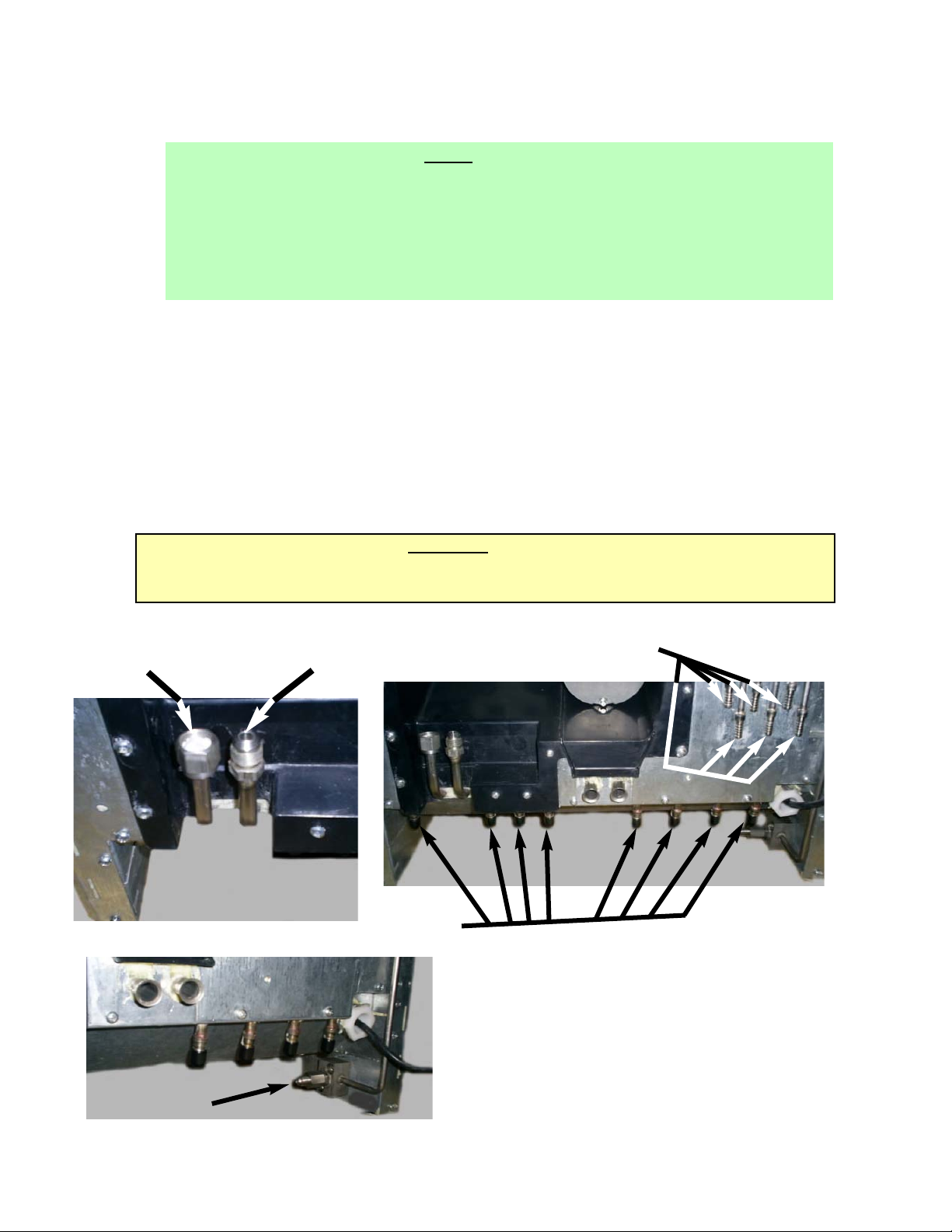
1.4 INSTALLING THE DISPENSER
A. Remove Cup Rest, Drip Tray, Splash Plate, and Top Cover.
B. Remove Cover Plate at rear of unit if not a through-the counter-installation.
C. Connect water supply for carbonator/plain water to the 3/8 inch flare fittings at the front of the
unit (See Figure 2).
D. For the plain water supply line, the inlet water flowing pressure should be at least 75 PSI.
If the water pressure is lower than 75 psi flowing, a Water Booster system must
be used.
NOTE:
The Lancer Water Booster/Tank, PN MC-163172, is offered as a kit.
The Water Booster must be installed as close as possible to the plain water circuit inlet.
If the water flowing pressure is lower than 75 PSI at the plain water inlet, and a water booster
is NOT installed, all water products will not hold a proper flow rate and/or water/syrup ratio.
Additionally, flow conditions at the nozzle may be affected, for example, poor nozzle coning and
mixing.
2
Page 6
3
E. For the soda water supply line, the inlet water static pressure going into the carbonator pump
should NOT exceed 50 PSI. If the static water pressure exceeds 50 psi, a water regulator must
be installed before the carbonator water inlet.
NOTE:
The Lancer Pressure Regulator, PN 18-0306, is offered.
The regulator must be installed as close as possible to the water carbonator pump inlet.
There is no minimum water pressure value feeding the carbonator. If the water pressure does
not exceed 50 psi, but fluctuates over this value (for example, when water usage on other
equipment connected to the same water supply causes pressure “spikes”), the use of a water
regulator is also required.
F. Place CO2
Cylinder with regulator in a serviceable location and route CO2 supply line (75 PSI)
to the 1/4 inch flare fitting at the front of the unit (See Figure 3). Check for leaks.
G. Connect syrup supply lines to the 3/8 inch barb inlet fittings at the front of the unit (See
Figure 4), using BIB (Bag-In-Box) pumps. Check for leaks.
H. Connect flavor injection lines to the barb fittings at the front of the unit (See Figure 4). Check
for leaks.
I. Install Drip Tray and extend hose to open type drain.
J. Drain lines must be insulated with a closed cell insulation. Insulation must cover the entire
length of the drain hose, including fittings. The drain should be installed in such a manner that
water does not collect in sags or other low points, as condensation will form.
K. Install Cup Rest and Splash Plate.
L. Connect Power Cord to grounded electrical outlet.
WARNING:
ICE AUGER AND BIN AGITATION SYSTEM WILL OPERATE AUTOMATICALLY. DO NOT
PLACE HANDS OR ANY BODY PARTS WITHIN THE BIN OR IN THE ICE CHUTE.
M. Test Motor operation by pushing Ice Chute.
Figure 2
Plain Water
Inlet
Figure 4
Syrup
Connections
Flavor Injection Inlets
Figure 3
CO
2 Inlet
Carbonated
Water
Inlet
Page 7

4
N. Clean and sanitize dispenser (see Section 2).
O. Fill unit approximately half full with ice. Push Chute and check for ice delivery.
P. Fill unit with ice.
Q. Install Top Cover.
NOTE
Lancer does not recommend the use of shaved, flake, nugget, or pellet ice in dispensers not properly
equipped to do so.
R. Set brix ratio for beverage dispensing valves according to manufacturer's instructions.
1.5 OPTIONAL INSTALLATION OF SOLD-OUT DEVICE
A. An optional Sold-Out Device can be used to automatically shut off the Syrup Pump when the
Package(s) is empty. This stops the operation of the Pump and the exhaust of gas until a new
syrup package is connected to the Pump.
B. The Lancer Sold-Out device measures syrup vacuum in the Pump Inlet Line. When the Syrup
Package is empty, the Pump increases vacuum causing the device to shut off the gas pressure
to stop the Pump. The Lancer Sold-Out automatically resets, after new Syrup Packages are
connected.
2. CLEANING AND SANITIZING INSTRUCTIONS
2.1 GENERAL INFORMATION
A. Lancer equipment (new or reconditioned) is shipped from the factory cleaned and sanitized in
accordance with NSF guidelines. This equipment must be cleaned and sanitized after
installation is complete, and the operator of the equipment must provide continuous
maintenance as required by this manual and/or state and local health department guidelines to
ensure proper operation and sanitation requirements are maintained.
NOTE
The cleaning and sanitizing procedures provided herein pertain to the Lancer equipment
identified by this manual. If other equipment is being cleaned, follow the guidelines established
for that equipment.
B. Cleaning and sanitizing should be accomplished only by trained personnel. Sanitary gloves are
to be used during cleaning and sanitizing operations. Applicable safety precautions must be
observed. Instruction warnings on the product being used must be followed.
C. Water lines are not to be disconnected during the cleaning and sanitizing of syrup lines to avoid
contamination.
D. Do NOT use strong bleaches or detergents. They tend to discolor and/or corrode various
materials.
E. Do NOT use metal scrapers, sharp objects, steel wool, scouring pads, abrasives, solvents, etc.,
on the dispenser.
F. Do NOT use hot water above 140°F (60°C). This may damage certain materials.
2.2 REQUIRED CLEANING EQUIPMENT
A. Cleansers (for example, Ivory Liquid, Calgon, etc.) mixed with clean, potable water at a
temperature of 90 to 110 degrees Fahrenheit should be used to clean equipment. The mixture
ratio, using Ivory Liquid, is one (1) ounce of cleanser to two (2) gallons of water. A minimum of
five (5) gallons of cleaning mixture should be prepared. Any equivalent cleanser may be used
as long as it provides a caustic based, non-perfumed, easily rinsed mixture containing at least
two (2) percent sodium hydroxide (NaOH). Rinsing must be thorough and use clean, potable
water which is also at a temperature of 90° to 110°F.
NOTE
Extended lengths of product lines may require that an additional volume of cleaning solution be
prepared.
B. Sanitizing solutions should be prepared in accordance with the manufacturer's written
recommendations and safety guidelines. The solution must provide 50 to 100 parts per million
Page 8

5
(PPM) available chlorine. A minimum of five (5) gallons of sanitizing solution should be
prepared. Any sanitizing solution may be used as long as it is prepared in accordance with the
manufacturer's written recommendations and safety guidelines, and provides 50 to 100 parts
per million (PPM) available chlorine. Sanitizing solution is to be purged from line(s) and
equipment by flushing with product only until there is no after taste. Do not rinse with water.
NOTE
Please note that a fresh water rinse cannot follow sanitization of equipment. Purge only with
the end use product until there is no after taste in the product. This is an NSF requirement, since
residual sanitizing solution left in the system could create health hazards.
Extended lengths of product lines may require that an additional volume of sanitizing solution
be prepared.
C. Other
1. Clean cloth towels.
2. Bucket.
3. Small brush (PN 22-0017) - included with installation kit.
4. Extra nozzle.
5. Sanitary gloves.
2.3 DAILY CLEANING
A. Carefully remove the nozzle housings by turning counter-clockwise and pulling down from the
nozzle body.
B. Wash the nozzle housings in warm soapy water and rinse with clean warm water.
C. Wet a clean cloth in warm soapy water.
D. While the nozzle housing is removed, wipe down the perimeter and end of the nozzle body.
E. Fill a cup with clean warm water and rinse nozzle body.
F. Make certain that the nozzle o-ring is not torn or otherwise damaged. If necessary, replace
damaged o-ring with LANCER PN 02-0231.
G. Wet the inner surface of the nozzle housing with water and reinstall the nozzle housing by
sliding it over the nozzle body and turning clockwise to lock in position.
2.4 ICE BIN CLEANING - START UP AND MONTHLY
A. Disconnect Dispenser from power source.
B. Remove Top Cover
C. Melt out any remaining ice from the bin.
D. Remove Splash Plate, Drip Tray and front and rear bin covers.
E. Remove Agitator Pin from Agitator Shaft. Slide Agitator Shaft rearward out of Motor Shaft and
pull out of rear Bearing to remove.
F. Remove Dispensing Wheel from Motor Shaft by sliding rearward.
G. Remove Dispensing Wheel Shroud.
H. Using cleaning solution, described in Section 2.2, and a clean cloth or soft brush, clean all
removable parts, sides of Ice Bin, Ice Chute, and surface of aluminum casting.
I. Using hot water, thoroughly rinse away the cleaning solution.
J. Wearing sanitary gloves, soak a clean cloth towel in sanitizing solution, described in Section 2.2,
and wash all surfaces of removable parts, sides of Ice Bin, Ice Chute, and surface of aluminum
casting.
K. Wearing sanitary gloves, reassemble all removable parts.
L. Fill unit with ice and replace Top Cover.
NOTE
Lancer does not recommend the use of shaved, flake, nugget, or pellet ice in dispensers not properly
equipped to do so.
M. Reconnect Dispenser to power source.
Page 9

6
2.5 CLEANING AND SANITIZING BEVERAGE COMPONENTS - FIGAL SYSTEMS
NOTE
Extended lengths of product lines may require more time for flushing and rinsing lines than stated
below.
A. Disconnect syrup lines from syrup containers (for example, quick disconnects, figal containers,
etc.).
B. Connect hose half of syrup line to a syrup tank filled with clean, potable, room temperature
water. Connect CO
2 supply hose to tank and pressurize.
C. Activate valve until water is dispensed. Flush and rinse line and fittings for a minimum of
60 seconds to remove all traces of residual product.
W
ARNING
TO AVOID POSSIBLE PERSONAL INJURY OR PROPERTY DAMAGE, DO NOT ATTEMPT TO
REMOVE SYRUP TANK COVER UNTIL CO
2 PRESSURE HAS BEEN RELEASED FROM TANK.
D. Disconnect CO
2 supply hose from the water filled syrup tank.
E. Following the instructions as described in Section 2.2 above, mix appropriate amount of
cleaning solution. Fill a tank with this solution. Connect hose half of syrup line to the tank.
Connect CO2 supply hose to tank and pressurize.
F. Activate valve and draw cleaning solution through lines for a minimum of 60 seconds. This will
ensure line is flushed and filled with cleaning solution. Allow line to stand for at least
30 minutes.
G. Disconnect CO2 supply hose from the tank.
H. Connect hose half of syrup line to a tank filled with clean, potable, water at a temperature of
90° to 110°F. Connect CO
2 supply hose to tank and pressurize.
I. Activate valve to flush and rinse line and fittings for a minimum of 60 seconds to remove all
traces of cleaning solution. Continue rinsing until testing with phenolpthalein shows that the
rinse water is free of residual detergent.
W
ARNING
TO AVOID POSSIBLE PERSONAL INJURY OR PROPERTY DAMAGE, DO NOT ATTEMPT TO
REMOVE SYRUP TANK COVER UNTIL CO2 PRESSURE HAS BEEN RELEASED FROM TANK.
J. Disconnect CO2 supply hose from the tank.
K. Following the instructions as described in 2.2 above, mix appropriate amount of sanitizing
solution. Fill a tank with this solution. Connect hose half of syrup line to the tank. Connect
CO2 supply hose to tank and pressurize.
L. Activate valve and draw sanitizing solution through line for a minimum of 60 seconds. This
will ensure line is flushed and filled with sanitizing solution. Allow line to stand for at least
30 minutes.
M. Disconnect CO2 supply hose from the tank.
N. Reconnect syrup lines to syrup containers (for example, quick disconnects, figal containers,
etc.) and ready unit for operation.
O. Draw drinks to refill lines and flush the sanitizing solution from the dispenser.
NOTE
Please note that a fresh water rinse cannot follow sanitization of equipment. Purge only with
the end use product until there is no after taste in the product. This is an NSF requirement.
P. Test dispenser in normal manner for proper operation. Taste dispensed product to ensure there
is no off-taste. If off-taste is found, additional flushing of syrup system may be required.
Q. Repeat cleaning, rinsing, and sanitizing procedures for each valve and each circuit.
2.6 CLEANING AND SANITIZING BEVERAGE COMPONENTS - BAG-IN-BOX SYSTEMS
NOTE
Extended lengths of product lines may require more time for flushing and rinsing lines than
stated below.
A. Disconnect syrup quick disconnect coupling from syrup packages and connect coupling to a bag
Page 10

7
valve removed from an empty Bag-in-Box (BIB) package.
B. Place syrup inlet line in a clean container filled with clean, potable, room temperature water.
C. Activate valve until water is dispensed. Flush and rinse line and fittings for a minimum of
60 seconds to remove all traces of residual product.
D. Following the instructions as described in 2.2 above, mix appropriate amount of cleaning
solution in a clean container. Place syrup inlet line in container filled with cleaning solution.
E. Activate valve and draw cleaning solution through lines for a minimum of 60 seconds. This
will ensure line is flushed and filled with cleaning solution. Allow line to stand for at least
30 minutes.
F. Place syrup inlet line in a clean container filled with clean, potable, water at a temperature of
90° to 110°F.
G. Activate valve to flush and rinse line and fittings for a minimum of 60 seconds to remove all
traces of cleaning solution. Continue rinsing until testing with phenolpthalein shows that the
rinse water is free of residual detergent.
H. Following the instructions as described in 2.2 above, mix appropriate amount of sanitizing
solution in a clean container. Place syrup inlet line in container filled with sanitizing solution.
I. Activate valve and draw sanitizing solution through line for a minimum of 60 seconds. This
will ensure line is flushed and filled with sanitizing solution. Allow line to stand for at least
30 minutes.
J. Remove bag valve from quick disconnect coupling and reconnect syrup inlet line to syrup
package. Ready unit for operation.
K. Draw drinks to refill lines and to flush the chlorine sanitizing solution from the dispenser.
NOTE
Please note that a fresh water rinse cannot follow sanitization of equipment. Purge only with
the end use product until there is no after taste in the product. This is an NSF requirement.
L. Test dispenser in normal manner for proper operation. Taste dispensed product to ensure there
is no off-taste. If off-taste is found, additional flushing of syrup system may be required.
M. Repeat cleaning, rinsing, and sanitizing procedures for each valve and each circuit.
3. HOW TO OPERATE AND ADJUST THE LANCER FS22
3.1 NORMAL OPERATION
A. Fill cup with desired amount of ice.
B. Place cup under nozzle below desired brand.
C. Select up to two (2) desired bonus flavors from those available on the keypad, by pressing
against the flavor label once. Selection indicator light will illuminate, acknowledging selec-
tion(s).
D. Press and hold brand label to fill cup.
E. Top off cup as desired
3.2 PROGRAMMING AND SETUP SOFTWARE
A. INTRODUCTION
NOTE:
The following descriptions reflect Firmware Version V0.161 for the Controller Board and
Firmware Version V1.132 for the Valve Boards. Lancer reserves the right to make changes and
updates as required. If you have any questions regarding the latest versions of programs,
please contact your Lancer representative.
1. The Lancer FS22 has been factory preset to the settings necessary to comply with the
brand/flavor version of the unit requested by the customer.
2. Adjustments or upgrades should only be performed by trained personnel. For any
upgrades, an upgrade kit may be purchased. It will include all of the hardware required for
the upgrade, including bezels and valves.
3. The valves can be adjusted by scrolling through the menus (see Figure 5) using the UP and
DOWN arrows. By pressing the ENTER button, a submenu is revealed. In the submenu,
the individual valves can be adjusted to the desired configuration.
Page 11
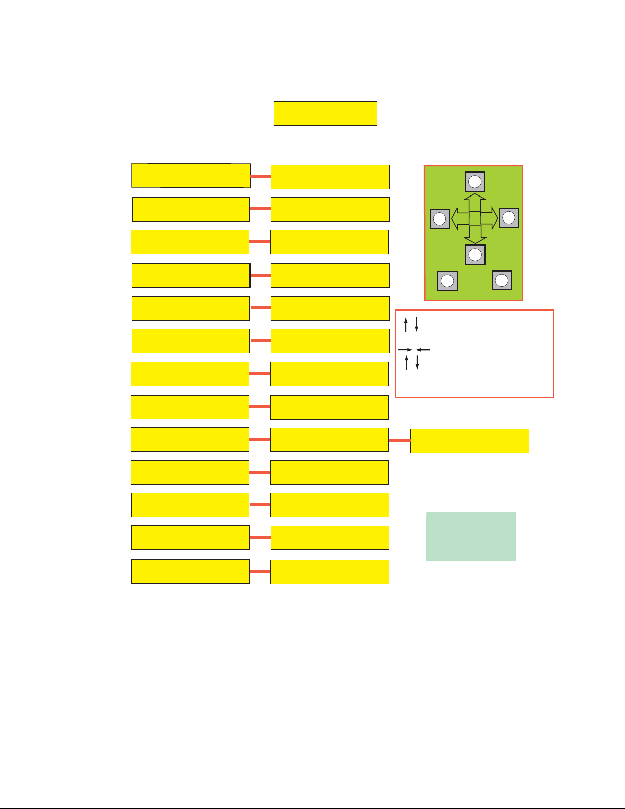
Figure 5
B. MENUS AND SUBMENUS
1. Bonus Flavors
a. Decide if the bonus flavors will be set to add an injected flavor to the brands or dispense
carbonated water/plain water.
b. Choose the Valve number (1-2) by scrolling UP and DOWN arrows.
c. Use the LEFT and RIGHT arrows to shift to the Top, Middle, or Bottom "bonus" flavors
categories.
d. Press the UP and DOWN arrows under Top, Middle, or Bottom to select it as an
injected flavor, carbonated Soda water, or plain Water.
e. Press ENTER to finalize settings. Panel lights should confirm finalized configurations.
8
INITIALIZATION SCREEN
(BOOT UP ONLY)
LANCER FS SERIES
VER. 0.161
MAIN MENU
FS-22 (NO PWB) C
MAJOR / MINOR
FS-22 (NO PWB) C
CONFIG BONUS KEY
FS-22 (NO PWB) C
CARB / WATER SETUP
FS-22 (NO PWB) C
CONFIG ICE TYPE
FS-22 (NO PWB) C
VW ICE STIR TMS
FS-22 (NO PWB) C
SYRUP PURGE
FS-22 (NO PWB) C
CONFIG KEY AS PC
FS-22 (NO PWB) C
PC SETTINGS
FS-22 (NO PWB) C
SOLD OUT
SUB-CATEGORY
BRANDS PER SIDE
V:1 L:2 R:2
BONUS KEY SETUP
V:1 T:F M:F B:F
CARB / WATER SETUP
V1 B1 SODA
CONFIG ICE TYPE
CUBE PELLET
ICE STIR ON 2000
ICE STIR OFF 60
SYRUP PURGE
OFF SINGLE ALL
CONFIG KEY AS PC
V1 B1 PC OFF
SET PC POUR SIZE
V1 B1 S F
SELECT SOLDOUT
SOLD OUT #1
CANCEL
Scrolls through Main Menu
Press "Enter" to enter sub-category
Moves cursor to right or left
Changes value (number/letter)
Press "Enter" to save changes
Press "Cancel" to exit menu
ENTER
2ND SUB-CATEGORY
SOLD OUT #1
OFF
FS-22 (NO PWB) C
SOFTWARE VERSION
FS-22 (NO PWB) C
NUMBER OF VALVES
FS-22 (NO PWB) C
RESET DEFAULTS
FS-22 (NO PWB) C
GLOBAL CONFIG
CONTROLLER X.XXX
V1 X.XXX
1 2
Y Y
RELOAD DEFAULTS?
NO YES
SET MAIN CONFIG
FS8 (PWB)
NOTE:
C = CUBED ICE
P = PELLET ICE
O = OVERRIDDEN
Page 12

9
2. Brands
a. Decide how the brands will be setup.
b. Choose the Valve number (1-2) by scrolling UP and DOWN arrows.
c. Use the LEFT and RIGHT arrows to shift to the Left or Right categories. The Left or
Right categories are set with the assumption that you are looking at them from the front.
d. Press UP and DOWN arrows under Left (1-2) or Right (1-2) to select the brand per side
as a single or double. For example, for bezel PN 05-2120, V:1 L:1 R:2
3. Soda/Water
a. Decide which switch locations will be carbonated and/or non-carbonated drinks.
b. Choose the Valve number (2-3) by scrolling the UP and DOWN arrows.
c. Use the LEFT and RIGHT arrows to shift to the number categories (1-4). The number
categories correspond to the brand location (per valve) that is being configured.
d. Press the UP and DOWN arrows under the number to select if that brand will be
carbonated Soda or non-carbonated plain Water. If a single brand per side, only
number 1 and/or 3 need to be set.
3.3 PURGING THE CARBONATION SYSTEM
A. A. Turn power off.
B. Turn the pressure adjusting screw on the CO
2 regulator counter-clockwise, all the way out.
C. The relief valve for the built-in carbonator is located on the right hand side behind the dispenser
splash plate. Lift the yellow lever on the top of the relief valve until water flows from the holes
in the relief valve. Allow pressure on the regulator to drop and then lock the relief valve lever
into place.
D. Turn the pressure adjusting screw on the CO2
regulator clockwise, until there is resistance.
Open the CO
2 cylinder handle slowly. Turn the CO
2 pressure regulator up (clockwise) slowly to
75 PSIG (5.1 bar).
E. Reconnect the power supply. The remote carbonator pump will activate periodically to fill
carbonator with the appropriate amount of water.
NOTE
To check for CO
2 leaks, close the valve on the CO2 cylinder and observe if the pressure to the
system drops with the cylinder valve closed for five (5) minutes. Open the cylinder valve after
check.
3.4 PURGING THE WATER AND SYRUP SYSTEMS
A. Open a dispensing valve until water and syrup are flowing steadily from the valve.
B. Repeat procedure "A" for each valve.
C. Check all of the unit's syrup and water connections for leaks and repair if necessary.
D. Replace the unit's splash plate and cup rest.
3.5 ADJUSTING WATER FLOW (LFCV
®)
A. The water flow can be adjusted between 2.50 oz/sec (73.9 ml/sec) and 3.75 oz/sec
(110.9 ml/sec) on all dispensing valves using the following procedure.
B. Ice should be on the cold plate for at least one (1) hour before you attempt to brix the valves.
The drink temperature should be no higher than 40°F (4.4°C) when the brix is set.
C. Remove dispenser merchandiser assembly.
D. Rotate switches panel, forward and down by releasing the two pin latches on its sides.
E. Rotate light panel, forward and up by releasing the two pin latches on its sides towards the top.
F. Remove nozzle by twisting counter clockwise and pulling down.
G. Install Lancer syrup separator (PN 54-0362) in place of nozzle.
H. Activate dispensing valve to fill separator syrup tube.
I. Hold a Lancer brix cup under the syrup separator and dispense water and syrup into cup for four
(4) seconds. Divide number of ounces (ml) of water in cup by four (4) to determine water flow
rate per second.
J. To obtain the proper flow, remove protective cap, and use a screwdriver to adjust water flow
control.
K. Repeat process for each "water valve". There can be up to six (6) gray "water valves" on this
dispenser [up to four (4) carbonated "water valves" and two (2) plain "water valves"].
Page 13

3.6 WEEKLY ADJUSTING OF WATER TO SYRUP (RATIO) BRIX (LFCV®)
A. Hold the Lancer brix cup under the syrup separator and activate valve. Check brix.
B. To obtain the proper brix, use screwdriver to adjust syrup flow control.
C. Once proper ratio is obtained repeat to verify.
D. Remove syrup separator (PN 54-0362 installed in Section 3.5.G above).
E. Install nozzle.
F. Repeat process for each valve.
G. Once all of the valves have been brixed, restore switches panel and light panel to their original
positions.
3.7 CARBONATOR PUMP MODIFICATIONS
NOTE
The electric, positive displacement, rotary vane pump with replaceable (250 PSI) bypass, is
maintenance-free. Only trained personnel should service pump. Additionally, it is not
recommended that the pump be used with hard water.
A. Servicing
1. Turn unit off.
2. Remove drip tray and splash plate.
3. Turn the CO
2 off, activate the relief valve.
4. Once the pressure has been released, untighten the inlet/outlet nuts into/out of the pump
3.8 PRIMING THE SYRUP PUMP AT THE CORRECT PRESSURE
For the Syrup Pump to operate correctly, it is necessary to remove all air from the system. After all
lines to the Syrup Pump and Syrup Packages are connected and CO
2 (or air pressure) is set, the
system should be primed as follows:
A. Disconnect Wire to Soda Solenoid or close Shut Off Valve on soda side so that only syrup will
be dispensed when Dispensing Valve is operated.
B. Operate Valve for five (5) seconds and then release for five (5) seconds. Continue drawing
syrup until flow is steady and full.
C. After priming, look for air pockets in Syrup Inlet or Outlet Lines. Repeat priming to remove any
air pockets found.
D. After priming, replace the Wire to Soda Solenoid or open Soda Shut Off Valve on Dispensing
Valve.
E. Repeat above procedure for all Syrup Pumps.
3.9 REPLENISHING BIB (BAG-IN-BOX) SYRUP SUPPLY
A. Remove empty Syrup Package from system by turning Collar on Quick Disconnect Coupling
counterclockwise.
B. On a new Package, push in on tab located above perforated opening flap.
C. After breaking seal on flap, pull the flap up.
D. Reach in the box and pull the Bag Valve out. Remove the Dust Cap.
E. Connect the Quick Disconnect Coupling by turning the Collar clockwise until stopped by the Bag
Valve.
F The Lancer Sold-Out Device will reset automatically.
G. If air has entered the Syrup System, prime the Syrup Pump following the instructions in
Section 3.3
10
Page 14

11
4. TROUBLESHOOTING GUIDE FOR FS22 DISPENSER
TROUBLE CAUSE REMEDY
4.1 No product when A. Keyswitch is off, or Keyswitch A. Turn Keyswitch "ON" and/or
switch is activated. harness disconnected. reconnect Keyswitch harness.
(Switch panel does B. 9-pin valve harness is B. Turn off power, reconnect 9-pin
NOT light up when disconnected. harness, and restore power.
activated). C. Faulty switch assembly. C. Replace switch assembly.
D. No power to unit. D. Check internal breaker and
incoming power.
4.2 No product when A. 25-pin valve harness A. Turn off power, reconnect 25-pin
switch is activated is disconnected. harness, and restore power.
(switch panel DOES B. Faulty switch assembly. B. Replace switch assembly.
light up when activated).
4.3 Push Chute and A. Dispenser not connected A. Connect Dispenser to power
nothing happens. to power source. source.
B. Microswitch defective. B. Replace Microswitch.
C. Wiring Harness not C. Plug in Wiring Harness.
plugged in.
D. PC Board defective. D. Replace PC Board.
4.4 Push Chute. Ice Door A. Wiring Harness not A. Plug in Wiring Harness.
opens but Motor does plugged in.
not run. B. PC Board defective. B. Replace PC Board.
C. Motor defective. C. Replace Motor.
4.5 Push Chute. Motor A. Solenoid not connected to A. Connect Solenoid to PC board.
runs but Ice Door PC Board.
does not open. B. Solenoid defective. B. Replace Solenoid.
C. PC Board defective. C. Replace PC Board.
D. Solenoid bracket screwed D. Unscrew solenoid bracket, raise
too low and not opening solenoid and re-screw bracket.
completely.
4.6 Push Chute, Ice Door A. Dispenser is out of ice. A. Fill unit with ice.
opens, Motor runs, B. Agitator Pin is missing or B. Replace Agitator Pin.
but no ice dispenses, damaged.
or ice is of poor quality. C. Poor ice quality. C. Install water filtration/purification
to ice maker supply water.
4.7 Valves do not operate. A. Keyswitch is off, or Keyswitch A. Turn Keyswitch and/or make sure
harness disconnected. Keyswitch harness is connected.
B. Circuit Breaker tripped. B. Reset Circuit Breaker.
C. Unit not plugged in. C. Plug in Dispenser.
4.8 Water in Ice Bin. A. Coldplate Drain is obstructed. A. Remove Splash Plate to obtain
access to Drain tubes and clear
accordingly.
4.9 Water leakage around A. Damaged or improperly A. If damaged, replace. If improperly
nozzle. installed o-ring on Nozzle. installed, adjust.
4.10 Miscellaneous leakage. A. Gap between parts. A. Tighten appropriate retaining
screws.
B. Damaged or improperly B. Replace or adjust appropriate
installed O-rings. O-rings.
4.11 Noisy/Cavitating A. Insufficient incoming water A. Verify incoming supply water
Carbonator Pump supply pressure. pressure to Carbonator Pump is a
minimum of 25 psi Carbonator
Pump (maximum of 50 psi).
Page 15

12
TROUBLE
CAUSE REMEDY
4.12 Insufficient "Soda" flow. A. Insufficient CO2 supply A. Verify incoming CO2 pressure
(Carbonated drinks) pressure. between 70 - 75 psi.
B. Shutoff on mounting block B. Open shutoff fully.
not fully open.
C. Foreign debris in Soda Flow C. Remove Soda Flow Control from
Control. valve and clean out any foreign
material to ensure smooth spool
movement.
4.13 Insufficient Water flow. A. Insufficient incoming supply A. Verify incoming supply water
(Plain Water drinks) pressure. pressure to Plain Water inlet is a
minimum of 70 psi (maximum of
125 psi).
B. Shutoff on mounting block B. Open shutoff fully.
not fully open.
C. Foreign debris in Water flow C. Remove Water Flow Control from
control. valve and clean out any foreign
material to ensure smooth spool
movement.
D. Water filtration problem. D. Service water system as required.
4.14 Insufficient syrup flow. A. Insufficient CO
2 pressure to A. Adjust CO2 pressure to 80 psi
BIB pumps. (Minimum: 70 psi) for BIB pumps.
B. Shutoff on mounting block B. Open shutoff fully.
not fully open.
C. Foreign debris in syrup flow C. Remove Syrup Flow Control from
control. valve and clean out any foreign
material to ensure smooth spool
movement.
D. Defective BIB Pump.` D. Replace pump.
4.15 Erratic ratio. A. Incoming water and/or syrup A. Check pressure and adjust.
supply not at minimum
flowing pressure.
B. Foreign debris in water and/or B. Remove flow control from
syrup flow control. suspected valve and clean out any
foreign material to ensure smooth
smooth spool movement.
C. CO
2 regulator malfunction. C. Repair or replace CO2 regulator,
as required.
4.16 Water only dispensed; A. Syrup BIB empty. A. Replace syrup BIB as required.
no syrup; or syrup only B. Water or syrup shutoff on B. Open shutoff fully.
dispensed; no water. mounting block not fully open.
C. Improper or inadequate water C. Remove valve from mounting block
or syrup supply. and open shutoffs slightly and
check water and syrup supply. If
no supply, check dispenser for
or other problems. Ensure BIB
connection is engaged.
D. CO
2 pressure to syrup D. Check the CO2 pressure to the
pump(s) too low. pump to ensure it is between
70 - 80 psi.
E. Stalled or inoperative E. Check CO2 pressure and/or
BIB pump. replace pump.
F. Kinked line. F. Remove kink or replace line.
G. C O2 Regulator malfunction. G. Repair or replace CO2 regulator
as required.
4.17 Valve will not shut off. A. Debris in solenoid seat. A. Activate valve a few times to try
and free debris. If that doesn't
eliminate the problem, remove the
solenoid coil and plunger, and
clean out any foreign material.
B. Solenoid plunger "sticking" B. Replace Solenoid coil.
Page 16

4.18 Syrup only dispensed. A. Improper water flow to A. Check for water flow to dispenser.
No water, but CO2 gas dispenser.
dispensed with syrup. B. Carbonator pump motor has B. Reset by turning the unit OFF and
timed out. (A message will and then ON (by using the Circuit
be displayed on the LCD Breaker on the Power Supply, or
screen). momentarily unplugging unit).
C. Liquid level probe not C. Check connections of liquid level
connected properly to PCB. probe to PCB assembly.
D. Faulty PCB assembly. D. Replace PCB assembly.
E. Faulty liquid level probe. E. Replace liquid level probe.
4.19 Excessive foaming. A. No ice in bin. A. Fill bin with ice , and allow
coldplate to re-stabilize.
B. Incoming water or syrup B. Correct prior to dispenser.
temperature too high.
C. CO2pressure too high. C. Adjust CO2 pressure downward,
but not less than 70 psi.
C. Water flow rate too high. D. Readjust and reset ratio.
E. Nozzle and diffuser not clean. E. Remove and clean.
F. Air in BIB lines. F. Bleed air from BIB lines.
4.20 Water continually A. Loose water connection(s). A. Tighten water connections.
leaking at connections. B. Flare seal washer leaks. B. Replace flare seal washer.
4.21 Water leaking from A. Securing screws loosened. A. Tighten screws.
Ice Door. B. Ice Door improperly seated. B. Reattach door assembly to
dispenser.
4.22 Circuit breaker tripping. A. Valve wire harness(es) A. Detect short by disconnecting valve
shorted to itself or Faucet harnesses from Switch Panel
Plate. [(4) 25-pin harnesses and
(4) 9-pin harnesses].
Restore power. If breaker does
NOT trip, then find and replace
shorted harness. If breaker still
trips, re-install the (8) harnesses,
and proceed to Step B, below.
B. Controller PCB is bad. B. Detect by disconnecting the white,
5-pin harness from the controller
PCB. Restore power. If breaker
does NOT trip, then replace
controller PCB. If breaker still trips,
re-install the white 5-pin harness
and proceed to Step C, below.
C. Secondary wire harness C. Locate short from a motor or
is shorted. solenoid harness, and replace as
` necessary.
D. Power Supply is bad. D. Detect short by disconnecting ALL
harness(es) connected to Power
Supply. Restore power. If breaker
still trips, replace Power Supply.
4.23 BIB pump does A. Out of CO2, CO2 not turned A. Replace CO2 supply, turn on CO2
not operate when on, or low CO
2 pressure. supply, or adjust CO2 pressure to
dispensing valve 70-80 psi.
is opened. B. Out of syrup. B. Replace syrup supply.
C. BIB connector not tight. C. Fasten connector tightly.
D. Kinks in syrup or gas lines. D. Straighten or replace lines.
4.24 BIB pump operating, A. Leak in syrup inlet or outlet A. Replace line.
but no flow. line.
B. Defective BIB pump check B. Replace BIB pump.
valve.
TROUBLE
CAUSE REMEDY
13
Page 17
14
4.25 BIB pump continues to A. Leak in suction line. A. Replace line.
operate when bag is B. Leaking o-ring on pump inlet B. Replace o-ring.
empty. fitting.
C. Defective syrup BIB pump. C. Replace defective pump.
4.26 BIB pump fails to A. BIB connector not on tight. A. Tighten BIB connector.
restart after bag B. BIB connector is stopped up. B. Clean out or replace BIB
replacement. connector.
C. Kinks in syrup line. C. Straighten or replace line.
4.27 BIB pump fails to stop A. Leak in discharge line or A. Repair or replace discharge line.
when dispensing valve fittings.
is closed. B. Empty BIB. B. Replace BIB.
C. Air leak on inlet line or bag C. Repair or replace.
connector.
4.28 Low or no carbonation. A. Low or no CO
2. A. Check CO2 supply. Adjust CO2
pressure to 70 psi.
B. Low water pressure. B. Need water a booster kit.
C. Worn or defective carbonator C. Replace carbonator pump.
pump.
D. Backflow preventer not D. Replace backflow preventer,
allowing water to flow. noting the flow direction arrow
(from pump-to-coldplate).
E. Probe malfunctioning. E. Replace Probe.
F. PCB malfunctioning. F. Replace PCB.
5. EXTRA CAPABILITIES
5.1 AUTOMATIC AGITATION AND RESETTABLE BREAKER
W
ARNING
THIS UNIT IS EQUIPPED WITH AUTOMATIC AGITATION. IT MAY ACTIVATE UNEXPECTEDLY.
DO NOT PLACE HANDS, OR FOREIGN OBJECTS IN THE ICE STORAGE COMPARTMENT.
WHEN UNIT IS BEING SERVICED, CLEANED, OR SANITIZED, UNPLUG DISPENSER FROM
THE POWER SOURCE.
A. Resettable breaker switch should not be used as a substitute for unplugging the dispenser from
power source to service unit.
B. Each Series 14400 ice beverage dispenser is equipped with automatic agitation for the ice bin.
1. The unit is shipped with timing set at two (2) seconds ON every 60 minutes for cubed ice.
2. The unit is shipped with timing set at four (4) seconds ON every 150 minutes for pellet ice.
5.3 DIAGNOSTIC
REPROGRAMMING
Only trained technicians should attempt any kind of reprogramming to new firmware version releases.
TROUBLE
CAUSE REMEDY
Page 18
15
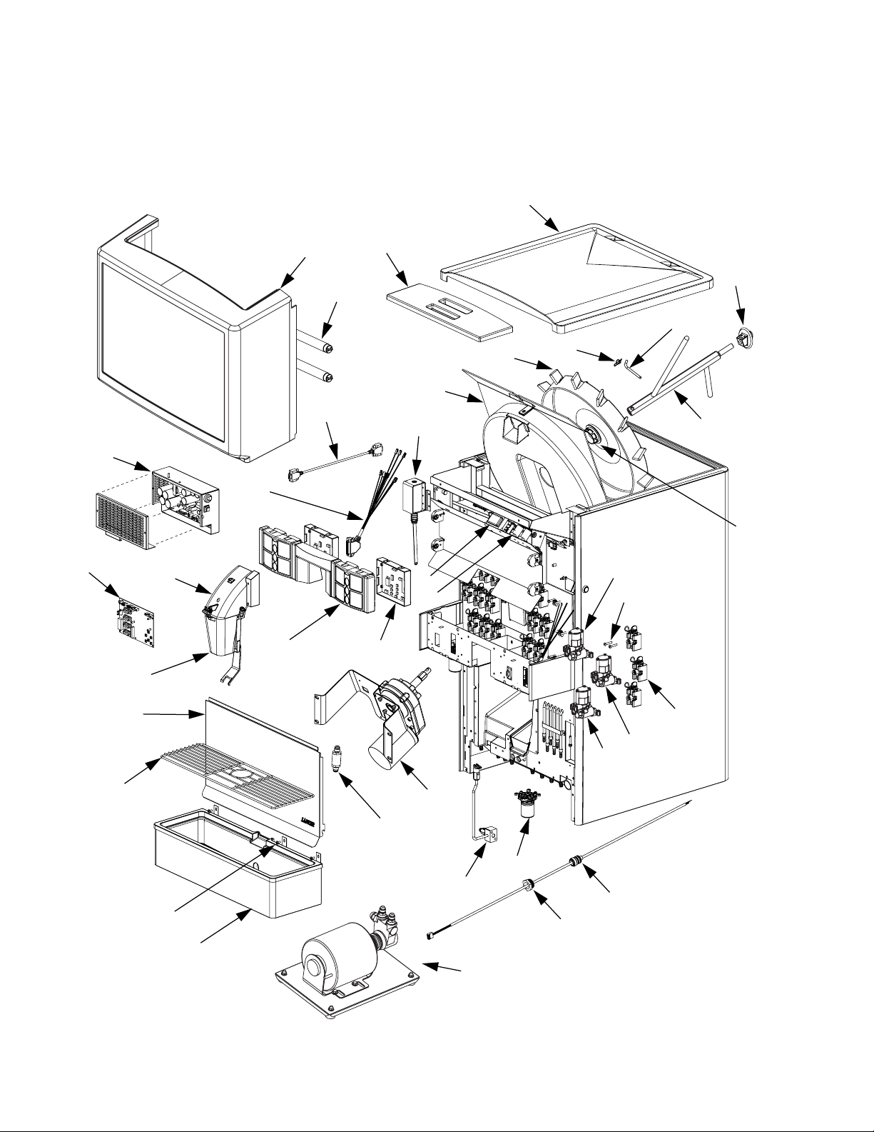
6. ILLUSTRATIONS AND PARTS LISTINGS
6.1 FINAL ASSEMBLY
22
31
30
32
26
34
29
27
28
23
35
25
37
24
36
21
18
19
20
17
16
13
15
33
4
14
12
11
3
6
5
8
7
10
2
9
1
38
Page 19

16
6.1 FINAL ASSEMBLY (CONTINUED)
Item Part No. Description
- 85-14408-06-2 IBD, ACMB, 22”, 150#, 8/6, LFCV
- 85-14408N-06-2 IBD, ACMB, 22”, 150#, 8/6, LFCV, Pellet
R 1 82-3441/01 Drip Tray Assy, IBD22
2 04-0236 Screw, 10-24 x 0.375, PHD,
PH, MS, SS
3 23-0669/01 Cup Rest, Wire, 22”, IBD
4 30-9194 Splash Plate, FS-8
5 17-0556. Check Valve, Vented,
5/8-18, Watts
R 6 82-3795 Motor Assy, Gear, 115V,
1/7HP, IBD
7 82-3370 CO
2 Assy, Inlet/P-Off, FS-16
8 54-0289 Nozzle Assy, Multi-Flavor
9 01-2214 Nut, Swivel, Probe, Carb,
FS-16
10 52-2751/02 Probe Cord Assy, Carb,
FS-16
R 11 82-3020 Valve Assy, LFCV, .2 Syrup
Injection, Natural (Spare
with Adapter)
R 12 82-3024 Valve Assy, LFCV, 3.0 - 4.5,
Soda/Water, Gray (Spare
with Adapter)
R 13 82-3023 Valve Assy, LFCV, 3.0 - 4.5,
Syrup, Black (Spare with
Adapter)
R 14 82-2317/01 Block Mounting Assy, SGL
15 04-1089 Screw, 10-32 x 1.000, RH,
PH/SL
16 02-0406 Seal, Shaft, Motor, IBD
17 23-1373 Agitator Assy, FS/IBD, HEX
18 05-1555 Bearing, Agitator, Rear, IBD
19 10-0762 Pin, Hex Design, FS-16
20 03-0368 Retainer, Pin, Agitator, IBD
R 21 82-3556 Dispensing Wheel Assy,
Hex
22 05-1467 Lid, Back, IBD22, RND
R 23 05-1476/01 Lid, Front, IBD, RND
Item Part
No. Description
R 24 05-1309/02-01 Shroud, Dispensing Wheel,
MOD, IBD
R 25 23-1029 Plunger Assy, Solenoid
R 26 52-2985 Harness, Valve 25-pin,
FS-16, Sealed
27 52-2686 Harness, Control-To-Valve,
9-pin, M/F, FS-8
R 28 12-0146/01 Lamp, 18”, 5W, T8, Daylight
29 82-3771 Merchandiser, Assy, FS-22
R - 06-2994-01 Graphic, FS-22,
Warm Blue
R - 06-2994-02 Graphic, FS-22,
Brilliant Yellow
R 30 82-3664 Assy, Switching Power
Supply, FS-8
R 31 52-2820/01 PCB Assy, FS-IBD
Controller Board
32 82-3538 Ice Chute Assy, IBD30,
Pellet
33 05-2258 Chute, Lower, IC
34 05-2058 Bezel, M-Brand, 2L/2R
35 82-3630 Switch Assy, FS, 2L/2R
36 12-0104 Starter, with Condenser,
IBD
37 12-0188 Ballast, Fluorescent Light,
LC-14-20-C
38 82-3791 Pump Assy, Remote, FS22,
1/3 HP
R in margin indicates change
Item Part No. Description
Page 20
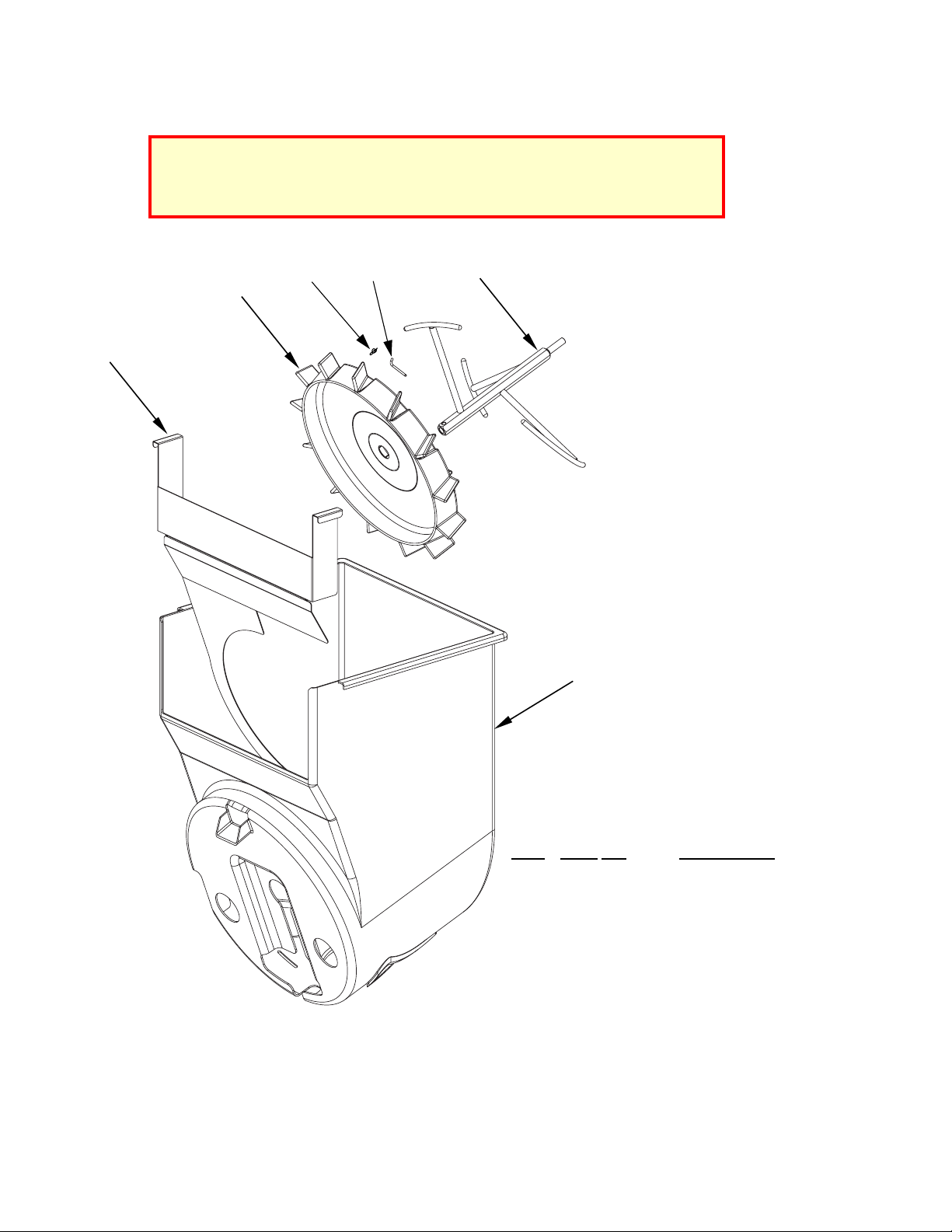
6.2 PELLET ICE ASSEMBLY AND PARTS LISTING
17
ITEM PART NO. DESCRIPTION
R 1 05-2325/01 Ice Shroud, IC
R 2 23-1401/01 Agitator Assy,
Helical, IC
3 10-0762 Pin, Hex Design,
FS-16
4 03-0368 Retainer, Pin,
Agitator, IBD
5 82-3651 Dispensing Wheel
Assy, Pellet Ice
R 6 30-9801/01 Shield, Nugget, IC
R in margin indicates change
NOTICE:
The Pellet Ice components listed on this Instruction Sheet are to be used ONLY in
conjunction with Nugget, Cubelet, or Chewblet ice. LANCER
makes no warranty of
any kind with regard to these components being used with any other kind of ice.
5
4
6
3
2
1
Page 21
18
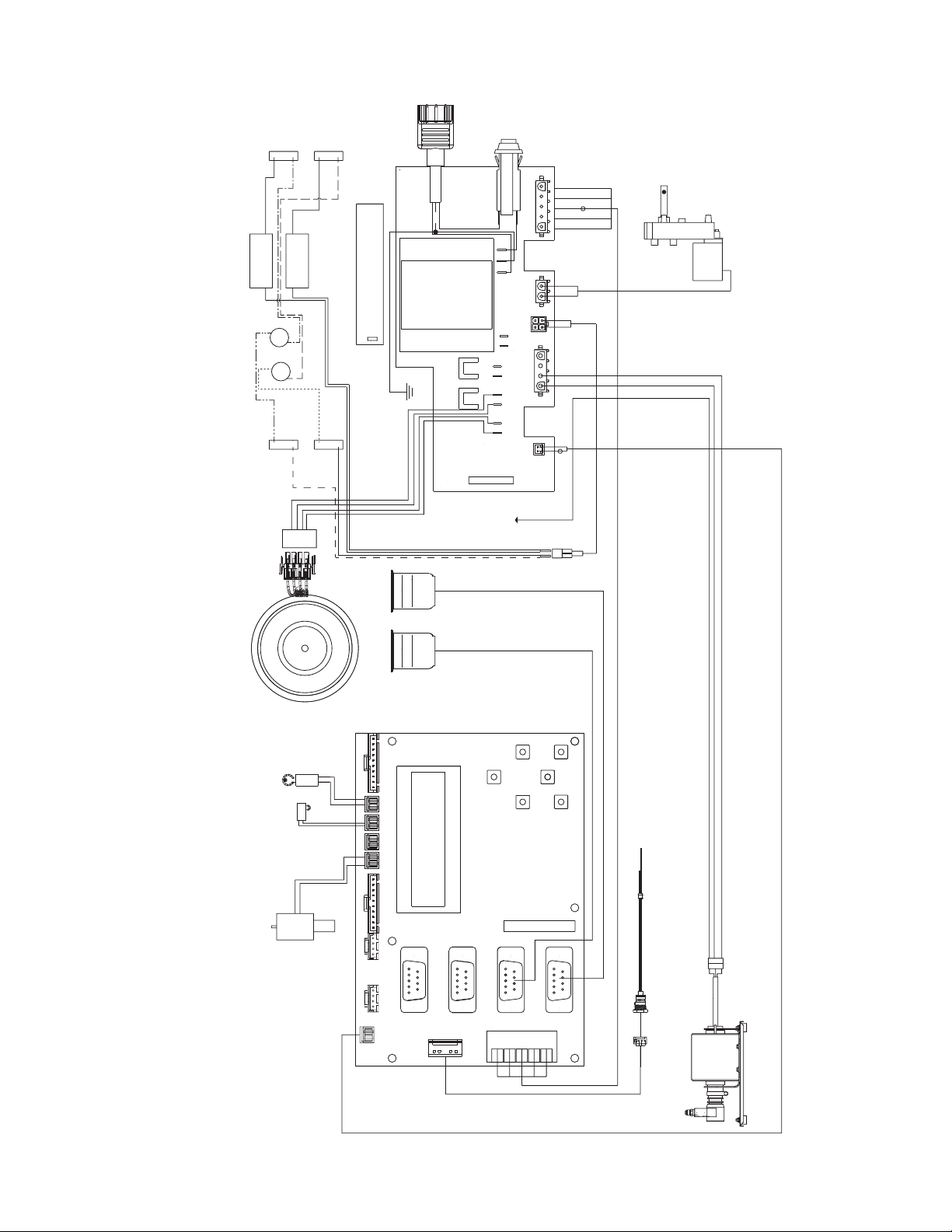
6.3 WIRING DIAGRAM (Figure Schematics)
POWER
CORD
BLACK
BLACK
BLK
WHT
FS22
LIGHTING
FLASH WHEN COMMUNICATING
LED COMMUNICATION LIGHTS
NOTE:
LED
BLACK
BLACK
WHITE
WHITE
GRN
POWER
SUPPLY
RESETTABLE
POWER
CONTROLLER
BLK
ICE
AGITATOR
BALLAST
CARBONATOR
AGI
CARB/
SWITCH
AGITATOR
SCREW
ICE DOOR
SOLENOID
GROUND TO
V1
NOZZLE
V2
NOZZLE
TRANSFORMER
WIRING DIAGRAM
KEY
ICE DOOR
SOLENOID
SWITCH
ICE
SWITCH
SOLD OUT
KEY
ICE
SWITCH
ICE DOOR
ICE OPTIC
FOT
COMM
CARB/AGI
DISPLAY
BOARD
CONTROLLER
JV4
JV3
CARB PROBE
POWER
JV2
PROBE
JV1
REMOTE PUMP
Page 22
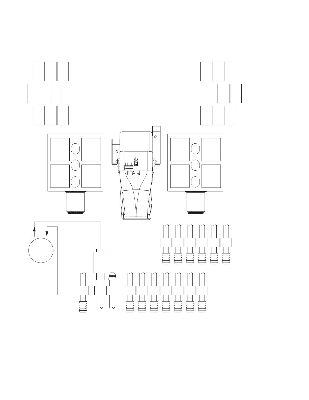
6.4 PLUMBING DIAGRAM WITH VALVE WIRING
19
BRN
BLK
S2-4
BLU
WHT
V2
IS2-3
BLU
BLK
S2-3
RED
GRY
SODA2
YEL
WHT
V2
IS2-2
RED
BLK
S2-1
YEL
BLK
S2-2
RED
BLK
S2-1
S2-2
RED
WHT
V2
IS2-1
YEL
GRY
WATER2
YEL
BLK
VALVE HARNESS
DIAGRAM
RED
BLK
S1-1
YEL
BLK
S1- 2
IS2-1
IS2-2
IS2-3
V2
BLU
BLK
S2- 3
BRN
BLK
S2- 4
WATER 1
IS1-1
IS1-2
IS1-3
V1
BLU
YEL
WHT
WHT
V1
V1
IS1-2IS1-3
BRN
YEL
BLK
BLK
S1-4 S1-2 S1-1
YEL
BLU
GRY
BLK
S1-3 SODA1
BLU
BLK
S1- 3
BRN
BLK
S1- 4
RED
WHT
V1
IS1-1
RED
GRY
RED
BLK
V
A
L
V
E
M
O
U
N
T
I
N
G
N
O
Z
Z
L
E
P
A
N
E
L
I
N
L
IS2- 3 IS2- 2
IS2- 1
IS1- 2IS1- 3
IS1- 1
PUMP
CHECK
VALV E
S2- 4
SODA
WATER
S2- 3
S2- 2
S2- 1
S1- 4
S1- 2S1- 3
S1- 1
E
T
F
I
T
T
I
N
G
S
WATER
SUPPLY
PLUMBING
DIAGRAM
Page 23

20
(Continued from previous page)
Bras Sulamericana LTDA. - Brasil
Contact: Fabio Queiroz
Rua. Dr. Ladislau Retti, 1400
Parque Alexandre
Cotia Sao Paulo - Brasil
CEP: 06714-150
Phone: 55-11-4612-1122
FAX: 55-11-4612-2219
e-mail: fabio.queiroz@bras.com.br
Lancer Chile Ltda. - Chile
Contact: Heriberto Concha
Vicuna mackenna 3019, San joaquin
Santiago, Chile
Phone: 56-2-5521657
FAX: 56-2-5521961
e-mail: lancerchile@lancer.tie.cl
Lancer Pacific
Web Site: www.lancerpacific.com
Australia
Lancer Pacific Pty Ltd
5 Toogood Avenue
Beverley 5009
PO Box 331
Welland 5007
South Australia
Phone: 61-8-8268-1388
FAX: 61-8-8268-1978
e-mail: joe-thorp@lancer-pacific.com.au
(Managing Director, Lancer Pacific)
steve-sotiriou@lancer-pacific.com.au
(for Fountain/soft drink)
bill-cadd@lancer-pacific.com.au
(for Draught Products)
New South Wales / ACT
Lancer Pacific Pty Ltd
Unit 8, 2 Holker Street
Newington 2127
New South Wales
Australia
Phone: 61-2-9648-6840
FAX: 61-2-9648-6850
e-mail: darren-castle@lancer-pacific.com.au
Victoria / Tasmania
Lancer Pacific Pty Ltd
55 Keele Street
Collingwood 3066
Victoria
Australia
Phone: 61-3-8415-1920
FAX: 61-3-8415-1929
e-mail: shane-devlyn@lancer-pacific.com.au
Queensland / Northern Territory
Lancer Pacific Pty Ltd
Unit 27, 256-258 Musgrave Road
Coopers Plains 4108
Queensland
Australia
Phone: 61-7-3274-5700
FAX: 61-7-3875-1805
e-mail: brett-thomson@lancer-pacific.com.au
Western Australia
Lancer Pacific Pty Ltd
24 Ernest Clark Road
Canning Vale 6155
Western Australia
Ph: 61-8-9455-2722
Fax: 61-8-9455-2455
Email: ross-kleinhanss@lancer-pacific.com.au
New Zealand
Lancer Pacific Ltd
9 O’Rorke Street
Onehunga, Auckland
POBox 12-523
Penrose, Auckland
New Zealand
Phone: 64-9-634-3612
Mobile Phone: 64-21-745-389
FAX: 64-9-634-1472
e-mail: mike-peffers@lancer-pacific.com.au
mark-hooper@lancer-pacific.com.au
Lancer Authorized Distributors
Indonesia
P.T. Dikarunia Sejahtera - Indonesia
JI. Gelong Baru Tengah #1A
Tomang, Jakarta, Barat 11440
Indonesia
Phone: 62-21-5694-3245
FAX: 62-21-560-6889
e-mail: dikarunia@cbn.net.id
Philippines
RBP Industrial Sales, Inc. - Philippines
Unit 20, 2/F, Facilities Centre Bldg.
548 Shaw Blvd
1552 Mandaluyong City
Philippines
Phone: 632-531-1221/1215/1289
FAX: 632-531-1271
e-mail: rbpsales@pldtdsl.net
rbp@pldtdsl.net
Lancer Asia
International Sales
6655 Lancer Blvd.
San Antonio, TX 78219
Phone: (210) 310-7000
FAX: (210) 310-7242
1-800-729-1500
e-mail: asia@lancercorp.com
Hong Kong
Patrick Co - Director Asia
Flat A, 24/F., Houston Industrial Bldg.
32-40 Wang Lung Street
Tsuen Wan, N. T., Hong Kong
Phone: 852-94302585
FAX: 852-24082605
e-mail: patrickco@lancer-asia.com
Lancer Authorized Distributors
Shanghai Freser International Co Ltd. - China
1856, Hu Tai Road
Shanghai, 200436, China
Phone: 86-21-5650-3555
FAX: 86-21-5650-2666
e-mail: daniel@freser.com.cn
Freser (HK) Company Ltd - Hong Kong
Flat A, 24/F., Houston Industrial Bldg.
32-40 Wang Lung Street
Tsuen Wan, N. T., Hong Kong
Phone: 852-2408-2595
FAX: 852-2408-2605
e-mail: freserhk@netvigator.com
Hayakawa Sanki - Japan
Hayakawa Sanki, Inc.
1-13-13, Kayaba-cho
Nihonbashi, Chuo-ku
Tokyo, 103-0025
Japan
Phone: 03-5651-1481
FAX: 03-5651-1445
e-mail: toshi@hayakawa-sanki.co.jp
Directory of USA - Canada Offices,
International Offices, and Authorized Distributors (Continued)
Tahoe Corporation - Korea
Tahoe Corporation
2FL, 835-66 Yocksam-dong
Kangnam-Ku
Seoul, Korea
Phone: 82-2-557-5612, -5614
FAX: 82-2-557-5615
e-mail: tahoepark@empal.com
Freser (MALAYSIA) SDN. BHD. - Malaysia
No. 31, Jalan TPP 5/13, Taman
Perindustrian Puchong, Seksyen 5,
47100 Puchong, Selangor, Malaysia
Phone: 60-3-8061-6666
FAX: 60-3-8062-1007
e-mail: freser@tm.net.my
Freser (S) Pte Ltd - Singapore
621 Aljunied Road
#02-09 Lipo Building
Singapore 389834
Phone: 65-6746-8191
FAX: 65-6746-8196
e-mail: fresersin@pacific.net.sg
Freser International Corporation - Taiwan
No. 76, Gui-Sui Street
Taipei 103, Taiwan R.O.C.
Phone: 886-2-2553-1555
FAX: 886-2-2553-2742
e-mail: herman@intl.freser.com.tw
Freser Makasan International Co., Ltd Thailand
Freser Makasan International Co., LTD.
Navanakorn Industrial Estate Zone 4
95/3 Moo 13, Klongnung, Klongluang
Patumthani 12120, Thailand
Phone: 662 520-3457 (Automatic, 7 lines)
FAX: 662 529-3840
e-mail: komsan@makasan.co.th
Lancer - Indian Sub-Continent
India
Shabbir Shafiqui - Area Manager
India and Sub-Continent
B-7, Pannalal Silk Mill Compounds
78, LBS Marg, Bhandup (W)
Mumbai 400-078, India
Phone: 91-22-67161200
Cell No: 91-98-67554152
e-mail: shafiquis@vsnl.com
Lancer Authorized Distributors
Western Refrigeration Ltd - India
B-7, Pannalal Silk Mill Compounds
78 L.B.S. Marg, Bhandup (W)
Mumbai 400-078, India
Phone: 91-22-67161200
91-22-67161201
FAX: 91-22-25962257
e-mail: parmeet@westernequipments.com
Bengal Marketing Company - Bangladesh
Skylark Point (6th Floor)
Room #G-2
24/A Bijoy Nagar,
Dhaka-1000, Bangladesh
Phone: 880-2-934-2987
FAX: 880-2-935-0127
e-mail: bmc@dhaka.agni.com
Dynamic Equipment - Pakistan
Dynamic Equipment and Controls (Pvt.) Ltd.
F-1/23, Canal Cottages, Block-D.
New Muslim Town.
Lahore. Pakistan.
Phone: 0092-42-583-6737
0092-42-583-6787
FAX: 0092-42-586-7924
e-mail: info@dynamic-eqpt.com.pk
m.ateeq@dynamic-eqpt.com.pk
Page 24

Directory of USA - Canada Offices,
International Offices, and Authorized Distributors
Corporate Office
6655 Lancer Blvd. • San Antonio, Texas 78219 • 210-310-7000 • 1-800-729-1500 • FAX 210-310-7250
Lancer USA
Manufacturing Locations
Foster Road Facilities-USA
6655 Lancer Blvd
San Antonio, TX 78219
Web Site: www.lancercorp.com
Phone: (210) 310-7000
MFG FAX: (210) 310-7088
ENG FAX: (210) 310-7096
ACCT FAX: (210) 310-7091
PURCH FAX: (210) 310-7094
Manufacturing - Mexico
Industrias Lancermex S.A. de C.V.
Victoria No. 2708 Nte Colonia Mundo Nuevo CP
260 10, Mexico
Phone: 011- 52 (878) 782-6600
FAX-Purchase: 011- 52 (878) 782-5401
FAX-Accounting: 011- 52 (878) 782-9240
FAX-Engineering: 011- 52 (878) 782-2302
Warehouse
Eagle Pass Warehouse
1793 Brown Street
Building A-2
Eagle Pass, TX 78852-5423
Phone: 830-757-5770
FAX: 830-757-4381
Lancer North America
USA - Canada Sales
6655 Lancer Blvd.
San Antonio, TX 78219
Phone: (210) 310-7000
SALES FAX: (210) 310-7245
CUSTOMER SERVICE FAX: (210) 310-7250
1-800-729-1500
Georgia Office
1125 Northmeadow Parkway, Suite 116
Roswell, GA 30076
Phone: (770) 343-8828
FAX: (770) 475-8646
1-800-729-1750
Lancer Authorized Distributors
Advanced Beverage Solutions (ABS)
100 N. Gary Avenue, Suite C
Roselle, IL 60172
Phone: (847) 524-1707
(877) 814-2271
FAX: (847) 524-1710
www.absone.com
Bevco
6900 Camille Avenue
Oklahoma City, OK 73149
Phone: (405) 672-7770
800-460-4238
FAX: (405) 672-7443
e-mail: sales@bevcoinc.com
Joe Kirwan Company
119 White Oak Lane
Old Bridge, NJ 08857
Phone: (732) 679-1900
FAX: (732) 679-9236
e-mail: sales@jkirwan.com
L & M Beverage Equipment Co. Inc.
12510 Santa Fe Trail Drive
Lenexa, KS 66215
Phone: (913) 888-8988
FAX: (913) 888-9137
e-mail: L7mco@aol.com
(Update #68 - as of July 17, 2006)
Ernest F. Mariani Company
614 West 600 South
Salt Lake City, UT 84104
Phone: (801) 359-3744
FAX: (801) 531-9615
e-mail: febell@efmco.com, or
clay@efmco.com
Mark Powers & Company, Inc.
P.O. Box 72
1821 Henry Street
Guntersville, AL 35976
Phone: (256) 582-6620
FAX: (256) 582-8533
e-mail: sales@markpowers-and-company.com
Maurer Supply, Inc.
843 Rainier Avenue South
Seattle, WA 98144
Phone: (206) 323-8640
FAX: (206) 323-9286
e-mail: maurersupply@qwest.net
Simgo Ltd.
5122 Timberlea Blvd.
Mississauga, Ontario L4W 2S5
Canada
Phone: 905-602-5800
FAX: 905-602-5804
e-mail: simgo@simgo.com
Simgo (B.C.) Ltd.
16-8125 - 130th Street
Surrey, B.C. V3W 7X4
Canada
Phone: 604-590-4022
FAX: 604-590-1601
Lancer Europe
Web Site: www.lancereurope.be
Belgium - European Central Office
Lancer Europe, S.A.
Mechelsesteenweg 592
B-1930 Zaventem
Belgium
Phone: 32-2-755-2390
FAX: 32-2-755-2399
e-mail: info@lancereurope.be
England
Managing Director
Contact: Paul Haskayne
Lancer G.B. Llp.
Unit 9 Prosperity Court, Midpoint 18
Middlewich CW10 OGD
Cheshire, United Kingdom.
Phone: 441606837711
FAX: +441606832705
e-mail: phaskayne@lancergb.co.uk
Hungary
H-2100 Gödöllõ
Isaszegi út 67
Hungary
Phone: 36-28-417-179
FAX: 36-28416-881
e-mail: bodolai@compuserve.com
Lancer International Sales, Inc.
Representation Office
Kashirskoe shosse, 65 (1), Office 610
Moscow 115583 Russia
Mail: Moscow, 115551, Mail Box #2, Russia
Mobile Phone: 7-495-991-7778
Office Phone: 7-495-727-4063
Office FAX: 7-495-727-4064
e-mail: Vladimir.Demkin@ornet.ru
lancer@online.ru
Egypt / Middle East
Elsayed Moniem - Regional Manager
Lancer Middle East/Africa
7 Mubarak Street
East Ain Shams 11311
Cairo, Egypt
Phone: 2-02-49-35-395
FAX: 2-02-49-33-914
Mobile Phone (GSM): 2-010-500-4007
e-mail: elsayed_lancer@msn.com
Lancer Authorized Distributors
Complete Beverage Services, Ltd.
Republic of Ireland and Northern Ireland
Gortrush Industrial Estate
Omagh County Tyrone
Northern Ireland
Office: 44-1662 250 008
FAX: 44-1662-252-991
DispenseTech - South Africa
P.O. Box 17495
Sunward Park, 1470
South Africa
Phone: 27-11-397-7455
FAX: 27-11-397-7648
e-mail: david@dispensetech.co.za
Lancer Latin America
Latin America Sales
6655 Lancer Blvd.
San Antonio, TX 78219
Phone: (210) 310-7000
1-800-729-1500
FAX: (210) 310-7245
e-mail: latinamerica@lancercorp.com
Lancer de Mexico, S.A. de C.V.
Contact: Carlos Robles
Calle Lerdo De Tejada #544 PTE.
Col. Las Villas
San Nicolas De Los Garza, N.L.
Mexico C.P. 66422
Phone: (52)-81-83-05-81-00
Phone: (52)-81-83-05-81-01
Phone: (52)-81-83-05-81-02
FAX: (52)-81-83-05-81-09
e-mail: Carlos.robles@lancer.com.mx
PEL SudAmerica - Ecuador
Lancer Sales Company
Contact: Luciano Lopez
Luis De Beethoven #N4756
Y Capitan Rafael Ramos
Sector Las Acacias
Quito, Ecuador
Phone: (5932) 2406346, 2407289, 2400937
FAX: (5932) 2405371
e-mail: Llopez@ecnet.ec
Lancer Authorized Distributors
PromoVen, S.A. - Argentina
Contact: Rafael Mendoza
Juncal 858 - Piso 3 Depto. “L”
(1062) Buenos Aires
Argentina
Phone: (54.11)4394.7654
FAX: (54.11)4394.1193
e-mail: promoven@fibertel.com.ar
depositopromoven@fibertel.com.ar
(Continued on reverse)
21
Please refer to the Lancer web site
(www.lancercorp.com) for information
relating to Lancer Installation and
Service Manuals, Instruction Sheets,
Technical Bulletins, Service Bulletins,
etc.
 Loading...