

Page 1
INSTALLATION AND SERVICE MANUAL
FOR
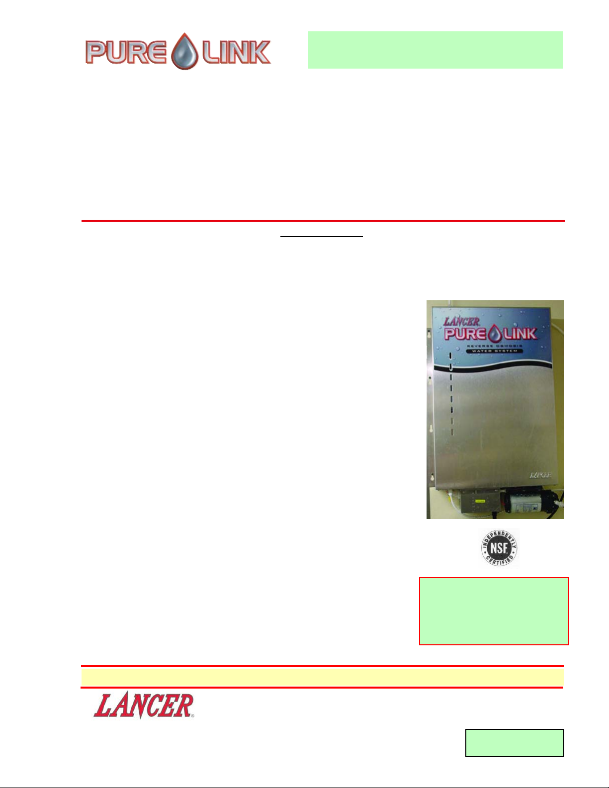
PURE LINK WATER SYSTEMS
LANCER SERIES 1300
DATE: 06/17/03
P.N. 28–0461/03
This Manual supersedes the Installation and Service Manual 28-0461/02, dated 04/23/03
6655 LANCER BLVD. • SAN ANTONIO, TEXAS 78219 USA • (210) 310-7000
"Lancer" is the registered trademark of Lancer • Copyright — 2003 by Lancer, all rights reserved.
FAX SALES • USA-CANADA – 210-310-7250
Warranty / Technical Support - Field • 800-729-1500
Customer Service • Domestic / International – 800-729-1500
SPECIFICATIONS
DIMENSIONS
WIDTH 18 3/4 Inches (47.63 cm)
DEPTH 4 5/8 Inches (11.75 cm)
HEIGHT (with Boost Pump 29 Inches (73.66 cm)
and Transformer)
WEIGHT
Shipping (with Boost and 33.60 pounds (15.24 kg)
Delivery Pump, Transformer,
and two Modules)
Gross Operating (with Boost and 60.60 pounds (24.79 kg)
Delivery Pump, Transformer,
and two Modules)
ELECTRICAL REQUIREMENTS (Only when Booster Pump is included)
100V/50-60Hz 1.2 Amps
115V/60Hz 0.8 Amps
230V/50-60Hz 0.4 Amps
WATER REQUIREMENTS
Potable Water Supply
STORAGE CAPACITY
Storage Unit 4.00 Gallons (15.14 Liters)
One (1) Membrane Unit 4.00 Gallons (15.14 Liters)
Two (2) Membrane Unit 4.00 Gallons (15.14 Liters)
PRODUCTION RATE, WITH BOOST PUMP (@ 60psi, 77°F INLET)*
One (1) Membrane Unit 170.85 GPD* (646.7 LPD)
Two (2) Membrane Unit 269 GPD (1018.3 LPD)
*Gallons per Day
(Continued on inside cover page)
Please refer to the Lancer web site (www.lancercorp.com) for
information relating to Lancer Installation and Service Manuals,
Instruction Sheets, Technical Bulletins, Service Bulletins, etc.
System Tested and Certified by
NSF International against
NSF/ANSI 58 for the reduction of
Barium, Hexavalent Chromium,
Radium 226/228, TDS, and Cysts.
Page 2

(Continued from cover page)
WORKING PRESSURE
Minimum 30 psi (206.8 KPa)
Maximum 120 psi (827.4 KPa)
Maximum inlet pressure 80 psi (551.6 KPa)
(with boost pump)
OPERATING TEMPERATURE
Minimum 40°F (4.4°C)
Maximum 113°F (45°C)
FLOW RESTRICTOR RATIO (REJECT PRODUCT)
One (1) Membrane Unit 3:1
Two (2) Membrane Unit 2:1
Efficiency rating, as verified by testing in accordance with NSF/ANSI 58:
One Membrane 16.96%
Two Membrane 18.46%
Efficiency rating means the percentage of the influent water to the system that is available to the user as
reverse osmosis treated water under operating conditions that approximate typical daily usage.
NOTES:
This system conforms to NSF/ANSI 58 for the specific performance claims as verified and substantiated by test data.
*Testing was performed under standard laboratory conditions - actual performance may vary.
PERFORMANCE DATA
This system has been tested according to NSF/ANSI 58 for reduction of the substances listed
below. The concentration of the indicated substances in water entering the system was
reduced to a concentration less than or equal to the permissible limit for water leaving the
system, as specified in NSF/ANSI 58.
Substance Influent Challenge Maximum Permissible
concentration mg/L Product Water
Concentration mg/L
Barium 10.0 + 10% 2.0
Chromium (hexavalent) 0.3 + 10% 0.1
Radium 226/228 25 pCi/L +
10% 5 pCi/L
Total Dissolved Solids (TDS) 750 + 40 mg/L 187
i
Substance Influent Challenge Reduction Requirement
Concentration
Cyst Minimum 50,000/ml 99.95%
Page 3

TABLE OF CONTENTS
SPECIFICATIONS......................................................................................................................................Cover
PERFORMANCE DATA ......................................................................................................................................i
TABLE OF CONTENTS .....................................................................................................................................ii
1. INSTALLATION ...........................................................................................................................................1
1.1 RECEIVING .................................................................................................................................................1
1.2 UNPACKING ......................................................................................................................................1
1.3 SELECTING INSTALLATION LOCATION..........................................................................................1
1.4 FILTERING THE WATER SUPPLY ....................................................................................................2
1.5 CONNECTING UNIT TO DRAIN........................................................................................................2
1.6 INSTALLING OVERFLOW.................................................................................................................2
1.7 CONNECTING UNIT TO POINT OF USE (POU)..............................................................................2
1.8 CONNECTING UNIT TO WATER SUPPLY .......................................................................................3
1.9 TURNING WATER ON .......................................................................................................................3
1.10 CONNECTING UNIT TO ELECTRIC POWER SUPPLY (IF EQUIPPED WITH
POWER SUPPLY)..............................................................................................................................3
1.11 BOOST PUMP BYPASS PRESSURE SETTING (IF SO EQUIPPED) ..............................................3
1.12 SANITIZING AND PURGING SYSTEM UPON INSTALLATION .......................................................4
2. INSTALLATIONS .........................................................................................................................................5
2.1 TYPES OF EQUIPMENT TO BE CONNECTED ...............................................................................5
2.2 INSTALLATION OF A FOUR (4) GALLON STORAGE UNIT TO SYSTEM (PN 85-1330) ................5
2.3 INSTALLATION OF OPTIONAL EQUIPMENT...................................................................................5
3. CLEANING AND MAINTENANCE ..............................................................................................................6
3.1 FILTER REPLACEMENT ...................................................................................................................7
3.2 WATER QUALITY ..............................................................................................................................7
4. MEMBRANE REPLACEMENT INSTRUCTIONS .......................................................................................7
5. REPLACING THE STORAGE BAG............................................................................................................8
5.1 PURE LINK SYSTEM WITH 4 GALLON STORAGE BAG ................................................................8
5.2 PURE LINK SYSTEM WITH 38.5 GALLON STORAGE BAG ...........................................................8
6. TROUBLESHOOTING.................................................................................................................................8
6.1 UNIT IS NOT MAKING WATER .........................................................................................................8
6.2 BOOSTER PUMP IS NOT RUNNING ...............................................................................................8
6.3 PRODUCTION RATE OF PURE WATER SEEMS TO BE SLOWING DOWN..................................8
6.4 NO WATER OR VERY LITTLE WATER FLOWING TO DRAIN ........................................................8
6.5 SYSTEM CANNOT KEEP UP TO HOST UNIT, ICE MAKER, COFFEE MAKER, ETC....................9
6.6 BOOSTER PUMP WILL NOT SHUT OFF ONCE THE BAG IS FULL OR WATER
FLOWS OUT OF OVER FLOW DEVICE AT TOP OF UNIT..............................................................9
6.7 SYSTEM CHATTER PRIOR TO SHUT OFF .....................................................................................9
TUBE CONNECTIONS ....................................................................................................................................10
7. ILLUSTRATIONS, PARTS LISTINGS, AND WIRING DIAGRAMS ..........................................................11
7.1 LANCER PURE LINK REVERSE OSMOSIS (RO) SYSTEM.....................................................11-12
7.2 LANCER PRE-FILTER KIT, TWIN-PAC, 5 MICRON (10” AND 20”)
(OPTIONAL EQUIPMENT)...............................................................................................................13
7.3 LANCER PURE LINK DELIVERY PUMP KIT, PN 82-3202 (OPTIONAL EQUIPMENT).................13
7.4 LANCER PURE LINK DELIVERY PUMP, PN 86-0139 (OPTIONAL EQUIPMENT) .......................14
7.5 LANCER PURE LINK DELIVERY PUMP, PN 86-0132 (OPTIONAL EQUIPMENT) .......................14
TEST EQUIPMENT (AVAILABLE THROUGH LANCER CUSTOMER SERVICE).........................................15
LANCER PURE LINK WATER UNITS ............................................................................................................16
CERTIFICATE OF WARRANTY ......................................................................................................................17
ii
Page 4
Pure Link
Return Water -
Optional Ice Maker
Vent
Assembly
1/4"
Tube
OD
To
Drain
Brine Water To Drain
Product Water To Carbonator,
Point Of Use, Or Delivery Pump
Carbonated
Water Out
Filtered Water To
Booster Pump Inlet
CAUTION
MUST have Carbon Pre-Filter
5 Micron Carbon Block NSF
Pure Link Installation With Delivery And Booster Pump
Tee Must Be Left
Open at Top
Filtered Water to Inlet
for Units Without
Water Booster Pump
Siphon
Break
(See Detail Drawing)
1
1. INSTALLATION
1.1 RECEIVING
A. Each unit is completely tested and thoroughly inspected before shipment. At the time of
shipment, the carrier accepts the unit and any claim for damage(s) must be made with the
carrier. Upon receiving units from the delivering carrier, carefully inspect carton for visible
indication(s) of damage. If damage exists, have carrier note same on bill of lading and file a
claim with the carrier.
1.2 UNPACKING
A. Remove the unit from carton.
B. Remove inner carton pads and plastic bag.
C. Remove Installation Kit of Loose parts.
D. Inspect for concealed damage(s); if evident, notify delivering carrier and file claim against same.
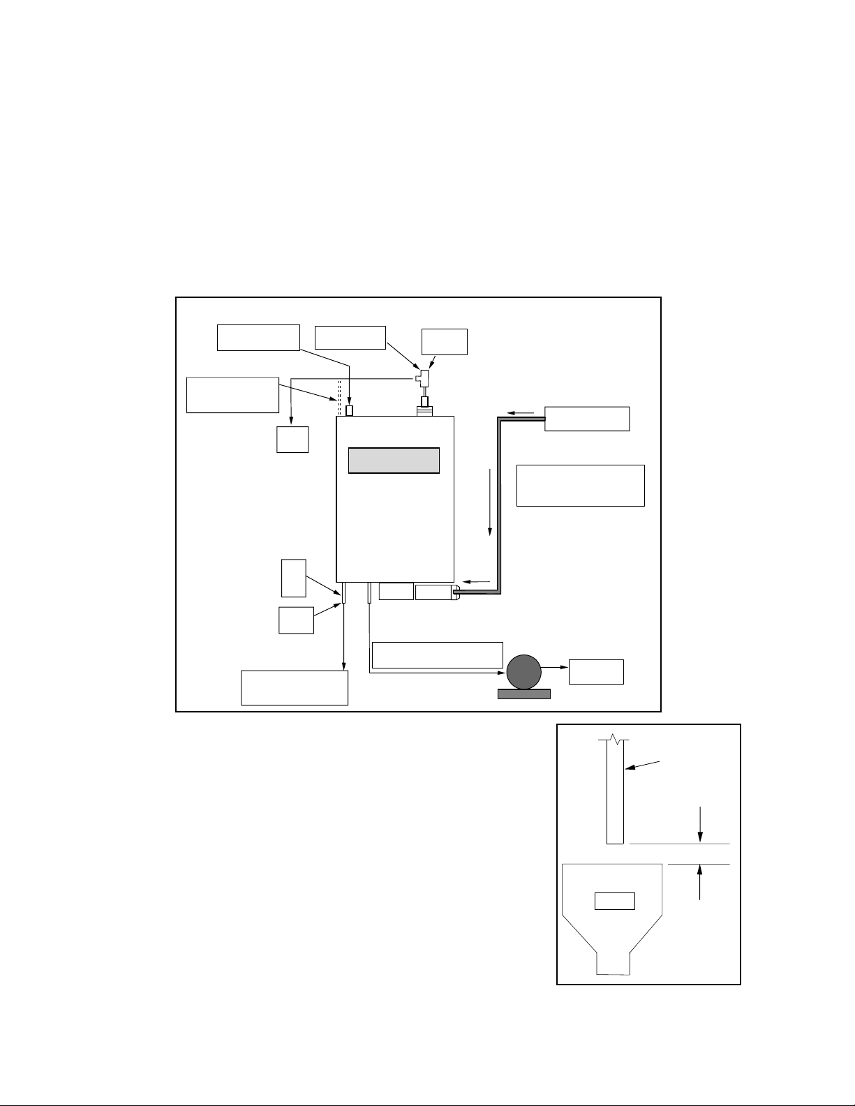
Installation Diagram
Figure 1
Air Gap
Figure 1a
1.3 SELECTING INSTALLATION LOCATION (SEE FIGURE 1)
A. The Pure Link unit is designed to attach to a vertical wall that
must be capable of supporting a minimum weight of 61 pounds
(27.7 kg). Select a location that is close to a drain, a municipal
water supply, and an electrical outlet (if required). If the unit
does not have a delivery pump, it should be mounted high
enough on the wall to allow gravity feed to the point of use.
NOTE: Lancer recommends installation height seven (7) feet (top of
unit) for gravity feed units. A minimum height of seven (7) feet is
required for use with the optional 38.5 Gallon Pure Storage unit.
If the building does not have a pre-filter and a carbon filter on the
incoming water supply to the unit, then allow enough space to
mount a dedicated pre-filter and a carbon filter.
B. Mount unit to wall in desired location. Ensure that unit is properly
secured based on operating weight.
Drain
1/4" Brine Water
from Pure Link
1" (Minimum)
Refer to Local
Plumbing Code
for Specific
Requirement
Page 5
2
1.4 FILTERING THE WATER SUPPLY
The Pure Link System is intended for use with potable water only. Excessive levels of chlorine, bacteria,
iron, turbidity, and/or hardness may affect the RO membranes or other components and may require
additional pre-filtration of the incoming water supply.
A. Water supplied to the Pure Link unit must first pass through a maximum 5 micron pre-filter and
then through a maximum 5 micron carbon block filter. The pre-filter removes suspended solids
and protects the carbon block filter from premature failure. The carbon block filter removes
chlorine and some organic compounds from the incoming water supply which can damage the
module.* The building must
have an adequate filtering system if a dedicated filter system is not
provided to the Pure Link unit. A Block Carbon pre-filter is required; otherwise, granular carbon
filters will release salt and carbon fines that will cause the booster pump to fail and not build
pressure.
* Not performance tested or certified by NSF.
CAUTION
FAILURE TO PROPERLY MAINTAIN AND CHANGE FILTER CARTRIDGES IN A TIMELY MANNER
WILL CAUSE THE PURE LINK UNIT TO REDUCE PRODUCTION AND/OR FAIL TO OPERATE.
B. In the event the building is not equipped with these filters, then a suitable pre-filter and a
carbon block filter must be installed and maintained at proper intervals. For selection of the
proper filtration system, refer to your Lancer Catalog or contact Lancer Customer Service.
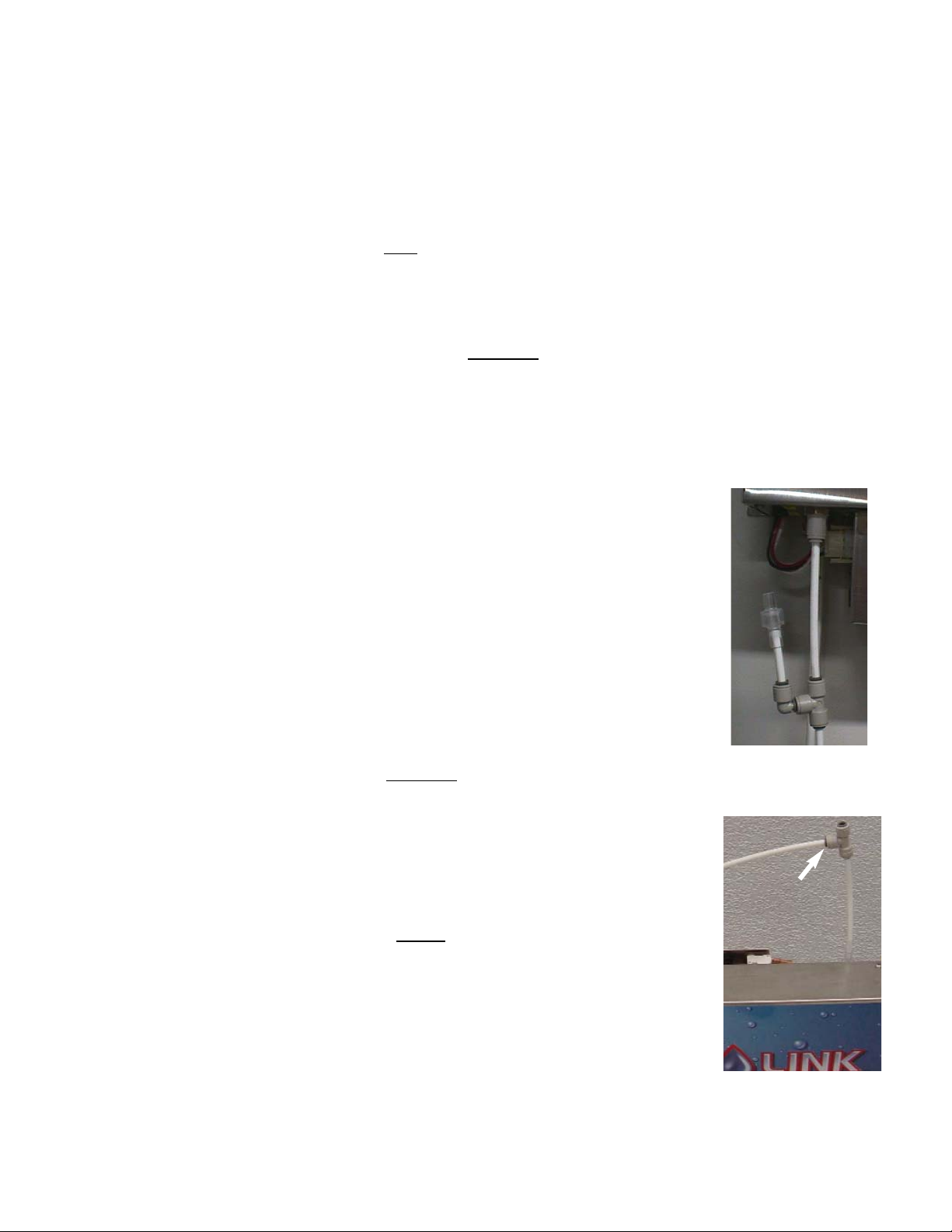
Overflow Assembly
Installation
Figure 3
Siphon Break
Installation
Figure 2
1.7 CONNECTING UNIT TO POINT OF USE (POU)
NOTE:
For selection of the proper filtration system, refer to your Lancer Catalog or
contact Lancer Customer Service.
The Pure Link unit has a connection on the bottom of the unit (marked
“Product Water Out”) which is the gravity feed port. For gravity feed
applications, connect 3/8” OD tubing to port and to the POU.
A. For Pressure Applications, connect 3/8” OD tubing to appropriate
Remote Delivery Pump.
B. Ensure that the Delivery pump is properly sized to meet the demand of
the Point(s) of Use (POU). Refer to Delivery Pump installation
instructions for proper installation.
Connect to Drain
1.5 CONNECTING UNIT TO DRAIN
The module drain is located on the bottom left hand side of the unit, marked
“DRAIN”. Install the siphon break (included in the Installation Kit) to the
“Drain port” of the unit (see Figure 2). Using 1/4” OD tubing, connect the
siphon break to the nearest suitable drain. Follow local plumbing codes for
air gap requirements (see Figure 1a).
1.6 INSTALLING OVERFLOW
A. The only time any water will vent from the overflow is if there is a
failure of the shut off valve to operate correctly and the unit continues
to produce water and overfills the storage bag causing the overflow
valve to vent water.
B. Insert six (6) inch length of 1/4” tubing (supplied with the Install Kit) into
the overflow valve on top right of unit (at location marked”VENT”).
Install the supplied 1/4”tee to tubing, as shown in Figure 3.
CAUTION
FAILURE TO PROPERLY INSTALL THE OVERFLOW ASSEMBLY OR
PLUMB IT TO THE DRAIN COULD RESULT IN WATER DAMAGE.
C. Plumb the overflow valve to drain (see Figure 3). Make sure that the
top of the tee is open to prevent siphoning of water from the storage
bag or backflow into the storage bag.
Page 6

3
C. For High Volume Applications, connect to optional storage unit.
D. When used with the optional 38.5 Gallon Pure Storage unit, the Delivery Pump must be installed
below the tank level to ensure proper operation..
1.8 CONNECTING UNIT TO WATER SUPPLY
A. The water inlet connection for units without
a water boost pump is on the top left hand side of
the unit. Connect to filtered water source using 3/8” OD tubing.
B. The water connection port, for units equipped with a water boost pump, is the inlet port on the
pump (see Figure 1). Connection can be accomplished using 3/8” OD tubing. As an
alternative, the Installation Kit contains an adaptor with a 3/8” barbed fitting. This allows the use
of 3/8” ID beverage tubing as the inlet water tube.
C. Use cold water supply ONLY.
CAUTION
THE UNIT COVER MUST BE PROPERLY INSTALLED ON UNIT DURING OPERATION WITH ALL
FIVE (5) SCREWS IN PLACE. FAILURE TO PROPERLY SECURE COVER TO UNIT WILL
RESULT IN FAILURE OF THE UNIT TO SHUT OFF AND/OR BOOST PUMP WILL OPERATE
CONTINUOUSLY IN BY-PASS.
1.9 TURNING WATER ON
Turn water on to unit and check for leaks. Membrane will begin to produce water to fill storage bag.
The time required to fill the bag is dependent upon the Pure Link model.Water production can be
verified by observing flow rate to drain. If equipped with internal delivery pump, disconnect 3 pin
pump connector from power supply. Follow Sanitizing Instructions in Section 1.12. Allow unit to fill
with water, then reconnect delivery pump.
1.10 CONNECTING UNIT TO ELECTRIC POWER SUPPLY (IF EQUIPPED WITH POWER SUPPLY)
W
ARNING
THIS UNIT MUST BE PROPERLY ELECTRICALLY GROUNDED TO AVOID POSSIBLE FATAL
ELECTRICAL SHOCK OR SERIOUS INJURY TO THE OPERATOR. THE POWER CORD IS
PROVIDED WITH A THREE PRONG GROUNDED PLUG. IF A THREE HOLE GROUNDED
ELECTRICAL OUTLET IS NOT AVAILABLE, USE AN APPROVED METHOD TO GROUND THE
UNIT.
DO NOT USE EXTENSION CORDS WITH THIS UNIT. DO NOT “GANG” TOGETHER WITH
OTHER ELECTRICAL DEVICES ON THE SAME OUTLET.
Plug unit power cord into transformer control box and into the proper electrical outlet. The water
boost pump will begin to operate. Product water will begin to fill the product water storage bag. The
boost pump will shut off when the storage bag is full.
1.11 Boost Pump Bypass Pressure Setting (if so equipped)
A. Install pressure gauge (0-160 psi) on outlet side of boost pump (PN 86-0112). Connect feed
water line from Pure Link unit to other side of gauge.
B. Turn on water supply.
C. Connect unit to electrical supply.
D. With boost pump operating, insert 1/16" hex key into bypass adjustment screw on pump head.
Turn clockwise to increase bypass setting, or turn counterclockwise to decrease bypass setting.
Set to 110 psi.
E. Disconnect electrical supply.
F. Turn off water supply.
G. Remove gauge and reconnect feed water line from Pure Link to boost pump outlet.
H. Turn on water supply and connect unit to electrical supply. Check for pump operation and leaks.
NOTE:
Pressure Test Gauge is available through Lancer Customer Service.
Page 7

4
1.12 SANITIZING AND PURGING SYSTEM UPON INSTALLATION
These instructions apply to all Pure-Link Models.
IMPORT
ANT:
When connecting to steamers, dough proofers, and ice makers, the equipment must be cleaned,
descaled, and sanitized in accordance with the manufacturer's instructions - prior to the operation
of Pure Link unit(s).
A. This equipment must be sanitized according to the manufacturer's instructions at the time of
installation. The operator of this equipment must provide continuous maintenance as required
by this manual and/or state and local health department guidelines to ensure proper operation
and sanitation requirements are maintained.
NOTE:
The cleaning and sanitizing procedures provided herein pertain to the Lancer equipment
identified by this manual. If other equipment is being cleaned, follow the guidelines established
by the manufacturer for that equipment.
1. Cleaning and sanitizing should be accomplished only by trained personnel. Sanitary gloves
are to be used during cleaning and sanitizing operations. Applicable safety precautions
must be observed. Instruction warnings on the product being used must be followed.
B. Membrane Flushing
NOTE:
The membrane is packaged with a preservative to extend shelf life; follow flushing instructions
prior to sanitizing and connecting to point of use.
1. Connect "Product Water" and “Drain” ports at bottom of unit to drain.
2. Turn on water supply and plug in power supply, if applicable.
3. Flush membrane product water and brine water to drain for 20 minutes.
4. Disconnect power supply and turn off water.
5. Connect "Product Water" port to point of use.
6. Proceed to Sanitizing instructions.
C. Recommended Preparation of Sanitizing Solutions
1. The Installation Kit includes a one (1) ounce (28.4 grams) Packet of Kay-5® Sanitizer for
sanitizing at start-up. This solution should be prepared in accordance with the
manufacturer's written recommendations and safety guidelines. Follow manufacturer's
guidelines on the packet label to provide a solution of five (5) parts per million (ppm)
Figure 4
available chlorine with the four (4) gallon storage capacity of
the Pure Link unit [0.08 ounce (2.5 grams) or approximately
1/2 teaspoon per Pure Link unit].
2. An equivalent sanitizer may be substituted as long as it is
prepared in accordance with the manufacturer's written
instructions and safety guidelines, and provides five (5) ppm
available chlorine when diluted with the four (4) gallon
storage capacity.
D. Sanitizing
1. Turn on water supply to unit (see Section 1.9) and plug unit
into electrical supply, if applicable. If unit is equipped with
internal delivery pump, disconnect 3 pin pump connector
from power supply.
2. Allow Pure Link to fill to about the top of the bag shelf. Water
should be visible through third sight “window” from bottom.
3. Remove cap fitting from “Return Water” port (top left of unit),
next to inlet. Retain cap fitting for reinstallation.
4. Insert sanitizer into storage bag through “Return Water” fitting using funnel supplied in the
Installation Kit (see Figure 4).
Page 8

Pure Link
Vent
Assembly
To
Drain
Brine Water To Drain
Product Water To Carbonator,
Point Of Use (POU), or Delivery Pump
Carbonated
Water Out
Filtered Water To Inlet
IMPORTANT
Mount Units Higher
Than Carbonator Inlet
Pure Link Installation With Storage Unit
Tee Must Be
Left Open at Top
3/8 X 3/8 X 3/8 Tee
Storage Only
Vent
Assembly
Siphon Break
5
5. Replace cap fitting on “Return Water” port, ensuring it is fully seated.
6. Allow unit to fill and shut off. (Boost pump will stop operating and water flow to drain will
stop. The backflush feature is indicated by a slow drip.)
7. Discard sanitizing solution to drain.
8. Allow unit to fill and shut off.
9. Discard rinse solution to drain.
10. Repeat rinse procedure (Steps 8 and 9) two (2) times.
11. Allow unit to fill and shut off. Unit is now ready for Point of Use.
12. If applicable, reconnect 3 pin pump connector to power supply.
2. INSTALLATIONS
2.1 TYPES OF EQUIPMENT TO BE CONNECTED
• FBD • Coffee Machine • Ice Tea (if installed)
• Espresso Machine • Carbonator • Proofer
• Ice Machine • Steamer
A. FBD and Carbonator Method
Gravity feed or remote pump system from Product Out port at the bottom of the Pure Link unit.
B. Coffee, Espresso, and Ice Tea Method
Use remote delivery pump kit. (Refer to Lancer Catalog or contact Lancer Customer Service.)
Figure 5
2.2 INSTALLATION OF A FOUR (4) GALLON STORAGE UNIT TO SYSTEM (PN 85-1330)
A. Receive and unpack storage unit (see Sections 1.1 and 1.2).
B. Mount to wall adjacent to the Pure Link Reverse Osmosis (RO) System and at same height.
The storage unit must be
installed at the same height of the Pure Link RO system to ensure
proper filling and shutoff of both units.
C. Connect to Pure Link RO System and into system as shown in Figure 5.
2.3. INSTALLATION OF OPTIONAL EQUIPMENT
A. Installation of a two unit system with two storage units (see Figure 6).
B. Installation of an integrated delivery system (see Figure 7).
Page 9

Pure Link
Vent
Assembly
To
Drain
Brine Water To Drain
Product Water To
Carbonator,
Point Of Use, Or
Delivery Pump
Carbonated
Water Out
CAUTION
MUST have Carbon Pre-Filter
5 Micron Carbon Block NSF
Pure Link Installation
Two Unit System with Two Storage Units
Tee Must Be Left
Open at Top
Pure Link
Storage
PN 85-1330
IMPORTANT
Mount Units Higher
Than Carbonator Inlet
Storage Only
PN 85-1330
SOURCE FROM
CARBON
PREFILTER
Water In To
Booster Pump Inlet
Figure 6
6
3. CLEANING AND MAINTENANCE
NOTE:
The Reverse Osmosis System contains a replaceable treatment component critical for effective reduction of
dissolved solids. The product water shall be tested periodically to verify that the system is performing properly.
TDS Sampling Kits and/or meters are available through Lancer Customer Service.
Figure 7
Pre-Filters
Inlet
INTEGRATED DELIVERY SYSTEM
Vent
Kit
Pure Link
85-1312-269
115 VAC
Drain Kit
1/4" Tube
To Drain
Tea
Expresso
Coffee
Page 10

7
3.1 FILTER REPLACEMENT
Periodic replacement of the sediment pre-filter and carbon block filter should be accomplished in
accordance with the manufacturer's instructions. Replacement of pre-filter and carbon block
cartridges should be scheduled as necessary with regard to filter size, feed water quality, and water
volume usage. Regular scheduled maintenance of the pre-filter is required to prevent premature
failure of Pure Link system components.
3.2 WATER QUALITY
Periodic water quality testing of the Product Water is recommended every six (6) months at a
minimum. When TDS reduction of system is less than 80% compared to untreated feed water,
Lancer recommends replacement of the Membrane Module(s). Sanitizing procedures should be
followed when necessary to reduce bacteria growth. See Section 1.12 of this Manual.
4. MEMBRANE REPLACEMENT INSTRUCTIONS
Single Membrane - Plumbing Diagram
Figure 8
Double Membrane - Plumbing Diagram
Figure 9
4.1 Disconnect electrical supply to Pure Link unit, if applicable.
4.2 Turn off water supply.
4.3 Drain water from storage bag.
4.4 Remove the five screws that secure the enclosure cover and remove cover (save screws for
reinstallation).
4.5 Remove 1/4" tubing from membrane module(s) by holding down color coded collet on membrane
port while pulling on tubing. Take care to note tube placement for reinstallation of replacement
membrane module(s).
NOTE:
Blue collet is feed water inlet, White collet is product water out, Red collet is brine water to drain.
Ensure that Flow Restrictor is properly seated in brine tube before insertion into red collet of
replacement membrane module. Flow Restrictor for single membrane unit is white, double
membrane unit is gray.
4.6 Remove membrane module(s) from mounting clips by firmly pulling out one end and then the other.
4.7 Install replacement membrane modules by firmly pressing into one mounting clip and then the other.
4.8 Reinstall 1/4" tubing to appropriate membrane ports. See Figures 8 and 9 for plumbing diagrams.
Ensure tubing is fully seated into fittings.
4.9 Turn on water supply and connect electrical supply, if applicable.
4.10 Check for leaks, and tighten connections if necessary.
4.11 Replace cover and secure with screws retained from Step 4.4 above. Do not allow bag to fill above
top of bag shelf before cover is in place.
TO STORAGE BAG
WATER OUT
INLET WATER
TO DRAIN
TO STORAGE BAG
WATER OUT
TO DRAIN
WATER IN
Page 11

4.12 Follow Membrane Flushing procedures as outlined in Section 1.12, this manual.
4.13 Lancer recommends replacing the storage bag when membrane module(s) are replaced.
5. REPLACING THE STORAGE BAG
5.1 PURE LINK SYSTEM WITH 4 GALLON STORAGE BAG (LANCER PN 82-3012)
A. With cover off of unit, locate the three (3) bag connectors, two (2) at the top of the bag and
one (1) at the bottom, mounted inside the bag shelf.
B. The translucent bag fitting adapter is affixed to the wall plate using a plastic horseshoe clip, this
does not need to be removed for this operation.
C. Remove bag by disconnecting the tan bag connectors from the translucent fitting adapters, this
is accomplished by pulling the tan bag connector down and away from the back mounting plate.
Repeat for the other two connectors.
D. Install new bag being careful to fully insert the connectors into the fitting adapters. There should
be no clearance around the circumference of the fitting interface.
E. Proceed to Sanitizing Instructions, Section 1.12.
5.2 PURE LINK STORAGE SYSTEM WITH 38.5 GALLON STORAGE BAG
If unit installation is also equipped with 38.5 Gallon Storage Bag(s), refer to Lancer Installation and
Service manual 28-0530/01, Pure Water Storage System, Lancer Series 1300.
6. TROUBLE SHOOTING
TROUBLE
CAUSE REMEDY
6.1 Unit is not making water. A. Water valve is not turned on. A. Turn on feed water to unit.
B. Plugged Pre-filters. B. Replace pre-filters.
C. Electrical not connected. C. Plug into AC outlet.
D. Membrane is clogged. D. Verify water production by
observing flow rate to drain.
Replace membranes, if
necessary.
E. Shut-off Lever stuck in closed E. Ensure shut-off lever is loose;
position. no obstruction on top of unit.
6.2 Booster pump is not A. Unit not plugged in. A. Plug into AC outlet. Plug cord
running. into transformer box.
B. Transformer has failed. B. Check electrical connections
with voltage meter. If necessary,
replace transformer.
C. Loose connections. C. Check all terminal connections.
D. Not plugged into transformer. D. Plug pump lead into transformer.
E. The reservoir is full and the E. Drain water from the bottom
pump is operating properly. port and check for booster pump
to engage.
6.3 Production Rate of Pure A. Pre-filters are clogged. A. Check for pressure drop by
water seems to slow Membranes have scaled. installing gauges at inlet and
down. outlet of pre-filters. There
should be only a slight pressure
drop after each location.
Replace filter cartridges or
membrane(s) as necessary.
6.4 No water, or very little A. Flow restrictor blocked. A. Remove cover and remove drain
water flowing to drain. tube from membrane drain outlet
port (outside center port at the
dual port end of the membrane
housing). Clean or remove
blockage.
B. Pre-Filters are clogged. B. Replace filter cartridges as
necessary.
8
Page 12

TROUBLE CAUSE REMEDY
6.5 System cannot keep up A. Host machine has malfunction, A. Contact your authorized service
to host unit, ice maker, or continuous leak. technician to fix the host
coffee maker, etc. equipment.
B. Pure Link production rate is B. 1. Add booster pump to
too low. increase line pressure
and production output.
2. Increase Pure Link
production by adding another
membrane.
3. If it is already a dual
membrane unit; add one (1)
or more systems, until the
desired daily water usage is
matched.
C. Membranes are scaled. C. Replace membrane(s) as
necessary.
D. Pre-Filters are clogged. D. Replace filter cartridges as
necessary.
6.6 Booster pump will not A. Shut off lever may be A. Locate the pump switch at the
shut off once the bag is obstructed. top of the unit. Ensure there is
full or water flows out of nothing obstructing the function
over flow device at top of the shut off lever.
of unit. B. Shut off lever is out of B. Locate the shut off lever at the
adjustment. top of the unit. Using care,
slightly bend the lever toward
front of unit on right hand side,
by hand.
6.7 System chatter prior to A. Shut off lever is out of A. Locate the shut off lever at the
shut off. adjustment. top of the unit. Using care,
slightly bend the lever toward
front of unit on right hand side,
by hand.
NOTES
9
Page 13

10
TUBE CONNECTIONS
NOTE: Lancer uses only genuine John Guest fittings in manufacturing the Pure Link system and associated components.
How to make a connection
To make a connection, the tube is simply pushed in by hand. The uniquely patented John Guest collet
locking system then holds the tube firmly in place without deforming it or restricting flow.
1. Cut Tube Square
Cut the tube square. It is essential that the outside diameter be free of score
marks and that burrs and sharp edges be removed before inserting into
fitting. For soft thin walled plastic tubing, we recommend the use of a tube insert.
Fitting grips before it seals. Ensure tube is pushed into the tube stop.
2. Insert Tube
4. Pull to check secure
3. Push up to Tube stop
Disconnecting
Push in collet and remove tube
Push the tube into the fitting, to the tube stop. The collet (gripper) has
stainless steel teeth which hold the tube firmly in position while the O-Ring provides
a permanent leak proof seal.
To disconnect, ensure the system is depressurized before removing the tube. Push in
collet squarely against face of fitting. With the collet held in this position, the tube can
be removed. The fitting can then be re-used.
Pull on the tube to check that it is secure. It is a good practice to test the system
prior to leaving site and/or before use.
Page 14
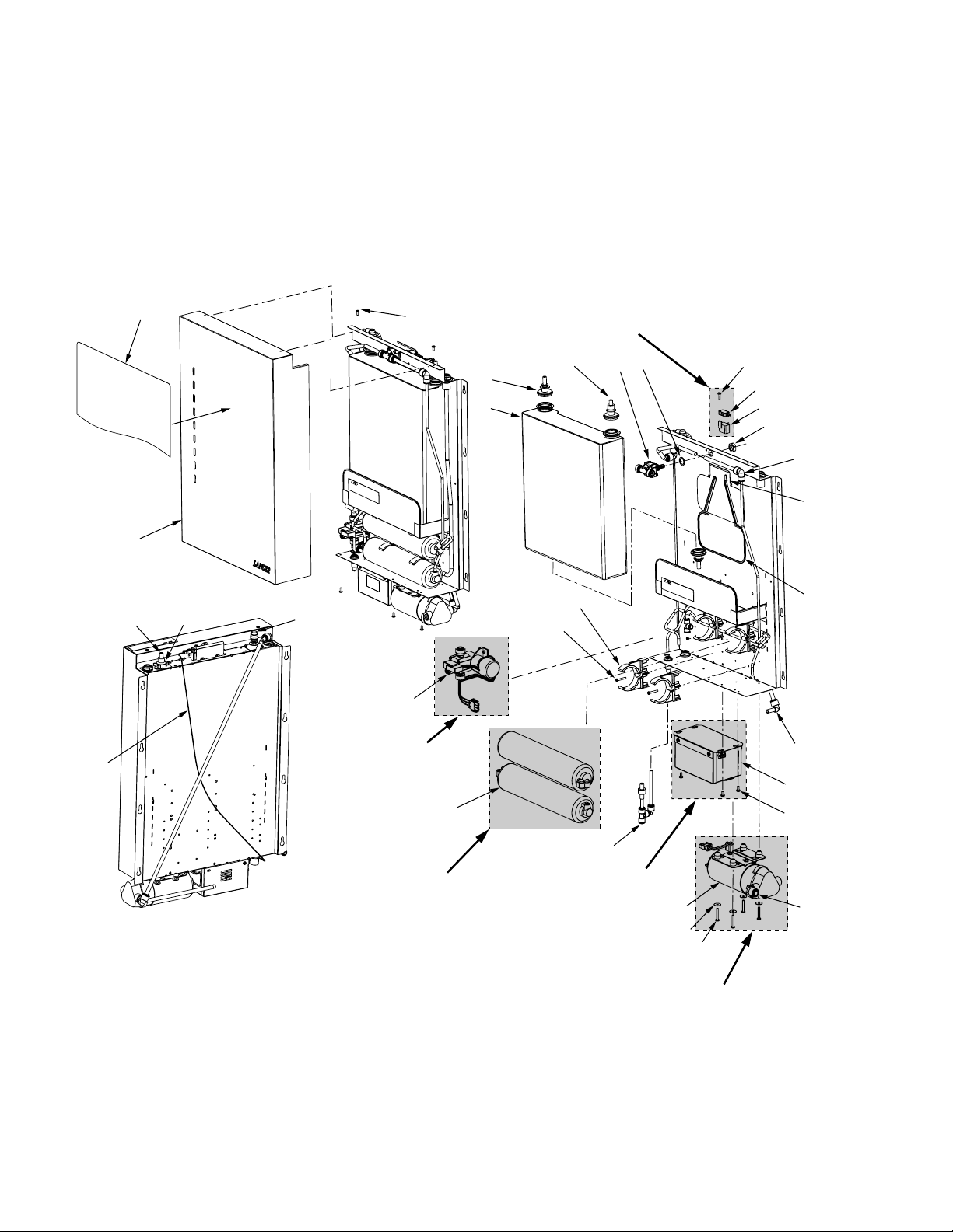
7. ILLUSTRATIONS, PARTS LISTINGS, AND WIRING DIAGRAMS
7.1 LANCER PURE LINK, REVERSE OSMOSIS SYSTEM
11
27
1
3
4
29
28
OPTIONAL ITEM
DELIVERY PUMP
FOR UNITS
MANUFACTURED
THROUGH
05/30/02
1 OR 2 MEMBRANE
2
26
25
OPTIONAL
OPTIONAL ITEM
WITH BOOST PUMP
3
6
5
23
24
OPTIONAL ITEM WITH
BOOST OR DELIVERY
PUMP
22
7
8
17
19
18
11
10
9
12
13
14
15
16
20
21
16
OPTIONAL ITEM
BOOST PUMP
Page 15

ITEM PART NO. DESCRIPTION
1 30-8164/01 Cover, Enclosure
2 04-0477 Screw, 8 - 32 x 0.375, PH
3 82-3402 Vent, Sub-Assy, Lancer Pure Link
4 52-2522 Wiring Harness, Pump
5 82-3012 Bag Assy, 4 Gallon
6 82-3010 Spout, Sub Assy, Pure Link
7 17-0579 Valve, Shut-Off, Mechanical, 3/8”
8 66-1038 Spacer, Valve, Shut-Off
9 04-1241 Nut, Jam, Nylon, 5/8 - 20
-- 82-3276 Kit, Boost Pump Switch, LPL
(Includes Items 9, 10, and 11)
10 12-0423 Switch, Miniature, 250VAC, 15
11 04-0268 Screw, 6 - 19 x 0.625LG, PLSTI,
HH
12 05-1921 Block, Mounting, Booster Pump
13 01-2469 Fitting, Reducer Elbow, 3/8 x 1/4
14 30-8161 Lever, Arm, Shut-Off
R 15 66-1023 Trim, Lever, Shut-Off
16 01-2084 Elbow, Plug-In, 3/8 x 3/8, JG
17 86-0112 Pump, Booster, 24V, 0.9 GPM
18 04-0481 Screw, 8 - 32 x 1.125, PH
19 04-1328 Washer, #8, 0.172 x 0.625 x
0.030
20 52-2540 Control Box Assy, Transformer,
115V
-- 52-2575 Control Box Assy, Transformer,
100V
-- 52-2576 Control Box Assy, Transformer,
230V
21 04-0477 Screw, 8 - 32 x 0.375, PH
22 82-3209 Kit, Drain, Siphon Break,
includes:
-- 01-2100 Fitting, Tee, 1/4”
-- 01-2077 Fitting, Elbow, Plug-In, 1/4 x 1/4
-- 17-0588 Valve, Check, Vent
-- 08-0414 Tubing, LLDPE, JG, 1/4”
23 05-1944 Clip, Membrane
24 04-0481 Screw, 8 - 32 x 1.125, PH
25 81-0534 Membrane, Water, 150 GPD-
OMN
26 86-0106 Pump, Water, 0.7 GPM, 24VDC,
30P (For units manufactured
through 05/30/02)
27 06-2591 Decal, Front, Pure Link
28 01-2479 Fitting, End Stop, 3/8 JG
7.1 LANCER PURE LINK, REVERSE OSMOSIS SYSTEM (CONTINUED)
12
ITEM PART NO.
DESCRIPTION
29 05-1915 Clip, Retaining, Bag
-- 08-0415 Tubing, LLDPE, JG, 3/8
-- 21-0752 Power Cord, IEC (USA, Mexico)
-- 21-0767 Power Cord, IEC SJT (Australia)
-- 21-0768 Power Cord, IEC SJT (UK,
Ireland)
-- 21-0769 Power Cord, IEC SJT (France,
Austria, Germany, Spain)
-- 21-0770 Power Cord, IEC (Italy, Chile)
-- 21-0771 Power Cord, IEC (Israel)
-- 21-0849 Power Cord, IEC (Japan)
R -- 82-3067-1311 Kit, Install (Units manufactured
through 05/19/03)
R -- 82-3067-1312 Kit, Install (Units manufactured
after 05/19/03)
R in margin indicates change or revision
NOTE: Lancer uses only genuine John Guest
fittings in manufacturing the Pure Link
system and associated components.
Page 16

7.3 LANCER PURE LINK DELIVERY PUMP KIT, PN 82-3202 (OPTIONAL EQUIPMENT)
ITEM PART NO. DESCRIPTION
1 86-0123 Pump, Delivery, 1.5 GPM, 115V
2 87-0018 Accumulator, 24 Oz, Shurflo
3 01-2295 Fitting, Male Connector, 3/8 JG x
1/2 MNPT
4 08-0415 Tubing, LLDPE, JG, 3/8
7.2 LANCER PRE-FILTER KIT, TWIN-PAC, 5 MICRON (10” AND 20”) (OPTIONAL EQUIPMENT)
ITEM PART NO. DESCRIPTION
-- 82-3021 10” Sump Kit, Twin-Pac, 5 Micron
-- 82-3078 20” Sump Kit, Twin-Pac, 5 Micron
1 82-3074 10” Pre-filter Cartridge, 5 Micron
-- 82-3081 20” Pre-filter Cartridge, 5 Micron
2 82-3075 10” Carbon Block Cartridge, 5 Micron
-- 82-3082 20” Carbon Block Cartridge, 5 Micron
13
Also see Lancer Instruction Sheet, 28-0515, on
the Lancer web site (www.lancercorp.com).
1
2
3
2
4
1
Page 17

7.5 LANCER PURE LINK DELIVERY PUMP, PN 86-0132 (OPTIONAL EQUIPMENT)
ITEM PART NO. DESCRIPTION
1 86-0132 Pump, Delivery, 115V, Variable
Speed, 4.5 GPM (open Flow)
R 2 01-2393 Fitting, Quick Connect x1/2 Barb,
90 Degree Elbow (Standard
Fitting)
R 3 01-2392 Fitting, Quick Connect x1/2 Barb,
Straight (Optional Fitting)
R in margin indicates change or revision
7.4 LANCER PURE LINK DELIVERY PUMP, PN 86-0139 (OPTIONAL EQUIPMENT)
14
ITEM PART NO. DESCRIPTION
1 86-0139 Pump, Delivery, 115V, Variable Speed,
1.2 GPM (Open Flow)
R 2 01-2393 Fitting, Quick Connect x1/2 Barb, 90
Degree Elbow (Standard Fitting)
R 3 01-2392 Fitting, Quick Connect x1/2 Barb,
Straight (Optional Fitting)
R in margin indicates change or revision
1
2
3
1
2
3
Page 18

TEST EQUIPMENT (AVAILABLE THROUGH LANCER CUSTOMER SERVICE)
Water Quality Test Kit, PN 82-3328
Tests for pH, Alkalinity, Chlorine, and Hardness
TDS Meter, PN 81-0581
1 PPM Resolution
TDS Meter, PN 82-3060
10 PPM Resolution
pH Meter, PN 81-0582
15
Page 19

LANCER Pure Link Water Generator Units
Part Number
Description
85-1311 LPL, Generator, Class 1, No Pumps
85-1311-167 LPL, Generator, Class 1, 100V, 50-60Hz, With Boost Pump
85-1311-267 LPL, Generator, Class 1, 115V, 60Hz, With Boost Pump
85-1311-367 LPL, Generator, Class 1, 230V, 50/60Hz, With Boost Pump
85-1311-158* LPL, Generator, Class 1, 100V, 50/60Hz, With Delivery Pump*
85-1311-258* LPL, Generator, Class 1, 115V, 60Hz, With Delivery Pump*
85-1311-358* LPL, Generator, Class 1, 230V, 50/60Hz, With Delivery Pump*
85-1311-157* LPL, Generator, Class 1, 100V, 50/60Hz, With Delivery and Boost Pump*
85-1311-257* LPL, Generator, Class 1, 115V, 60Hz, With Delivery and Boost Pump*
85-1311-357* LPL, Generator, Class 1, 230V, 50/60Hz, With Delivery and Boost Pump*
85-1312 LPL, Generator, Class 2, No Pumps
85-1312-167 LPL, Generator, Class 2, 100V, 50-60Hz, With Boost Pump
85-1312-267 LPL, Generator, Class 2, 115V, 60Hz, With Boost Pump
85-1312-367 LPL, Generator, Class 2, 230V, 50/60Hz, With Boost Pump
85-1312-158* LPL, Generator, Class 2, 100V, 50/60Hz, With Delivery Pump*
85-1312-258* LPL, Generator, Class 2, 115V, 60Hz, With Delivery Pump*
85-1312-358* LPL, Generator, Class 2, 230V, 50/60Hz, With Delivery Pump*
85-1312-157* LPL, Generator, Class 2, 100V, 50/60Hz, With Delivery and Boost Pump*
85-1312-257* LPL, Generator, Class 2, 115V, 60Hz, With Delivery and Boost Pump*
85-1312-357* LPL, Generator, Class 2, 230V, 50/60Hz, With Delivery and Boost Pump*
85-1312-269 LPL, Generator, Class 2, 115V, 60Hz, With External Delivery Pump
* This item no longer manufactured after 05/30/02
LANCER Pure Link Water Storage Units
Part Number
Description
85-1330 LPL, Storage Unit, 4 Gallon, No Pumps
85-1330-40 LPL, Storage Unit, 38.5 Gallon, No Pumps
LANCER Pure Link Water Units
16
An Explanation of LANCER's Pure Link Part Numbering System
4th Digit
Number of Membranes
(or Class) 1 , 2 or 3
3rd Digit
1 = Generator (R.O.
Purification System)
3 = Storage Systems
Series and Number
85 -
1 = 100V, 50-60Hz
2 = 115V, 60Hz
3 = 230V, 50-60Hz
13 X X
5 = With Delivery Pump
(Manufactured through 05/30/02)
6 = Without Delivery Pump
7 = With Boost Pump
8 = Without Boost Pump
9 = External Delivery Pump
Country Code
XXX
-
XX
-
Page 20

17
PARTS AND EQUIPMENT LIMITED WARRANTY
LANCER® warrants new replacement parts, equipment, and hermetically sealed refrigeration
systems (HSRS) to be free from defects in material and workmanship under normal use and
service. The duration of the warranty for these different items is shown below.
LANCER®‘s
obligation, hereunder, shall be limited to repairing or replacing any part, or part of said
equipment or system which our examination discloses to be defective and which has not been
subjected to any accident, negligence, alteration, abuse or misuse, and additionally in the case
of refrigeration and/or electrical systems, not subjected to high, low or fluctuating electrical
voltage.
LANCER®‘s obligation does not provide for service calls from factory representatives
or from any other agency and shall not include reimbursement for labor charges incident to
removal of any parts or the reinstallation of the same.
LANCER® will accept parts, equipment,
and refrigeration systems freight prepaid by sender. LANCER® will assume freight charges
within the continental United States, or to a port of export within the continental United States
for international shipments.
LANCER® will not be responsible for international freight, customs
fees or duties at country of destination. In the event LANCER®establishes sales and service
organizations outside the continental limits of the United States, the point of shipment of
repaired or replaced parts or equipment may, at
LANCER
®
option, be made from that location,
with freight charges assumed to the point of export from the country in which a sales and
service organization is established.
Warranty Periods
Par
ts:
Ninety (90) days from date of original shipment from a LANCER® facility or from
an authorized Lancer Distributor.
Equipment
:
One (1) year from date of original shipment from a LANCER® facility or from an
authorized Lancer Distributor.
Hermetically Sealed Refrigeration System
:
For the following components of the HSRS, i.e., the compressor, condenser,
evaporator, coldpack, capillary tubes, and drier, five (5) years from date of original
shipment from a
LANCER® facility or from an authorized Lancer Distributor.
All other parts of the HSRS, one (1) year from date of original shipment from a
LANCER® facility or from an authorized Lancer Distributor.
EXCEPT AS SPECIFICALLY SET FORTH HEREIN,
LANCER® MAKES NO EXPRESS
WARRANTIES AS TO ANY MATTER WHATSOEVER AND HEREBY DISCLAIMS ALL
IMPLIED WARRANTIES INCLUDING, WITHOUT LIMITATION, THE IMPLIED WARRANTIES
OF MERCHANTABILITY AND FITNESS FOR ANY PARTICULAR PURPOSE. IN NO EVENT
SHALL
LANCER® BE LIABLE OR OBLIGATED TO CUSTOMER OR TO ANY THIRD PARTY
FOR INCIDENTAL, CONSEQUENTIAL, OR SPECIAL DAMAGES, REGARDLESS OF THE
THEORY OF LIABILITY, ARISING OUT OF, OR IN ANY MANNER RELATED TO
LANCER®
PARTS, EQUIPMENT, OR HSRS, OR ANY DELAY WITH RESPECT TO ITS DELIVERY.
REV: 01/16/01
P.N.: 38-0508/03
 Loading...