

Page 1
POST MIX VALVE LEV® SERIES 100, 145
Operation Manual
PN: 28-0027/05
LEV®
PORTION CONTROL
MODEL 100L 3.0 LEV® MODEL 145L 4.5 LEV®
MODEL 100SSL 3.0 LEV® WITH MODEL 145SSL 4.5 LEV® WITH
SELF-SERVE LEVER SELF-SERVE LEVER
MODEL 100P 3.0 LEV® MODEL 145P 4.5 LEV®
PUSHBUTTON PUSHBUTTON
MODEL 100SF 3.0 LEV® MODEL 145SF 4.5 LEV®
SUREFILL SUREFILL
MODEL 100PC 3.0 LEV® MODEL 145PC 4.5 LEV®
PORTION CONTROL PORTION CONTROL
10011
14512
LEV®
PUSH BUTTON
“Lancer” is the registered trademark of Lancer © 2014 by Lancer, all rights reserved.
LEV®
PUSH BUTTON
LEV®
CREW SERVE
San Antonio, Texas 78219
Technical Support/Warranty: 800-729-1550
custserv@lancercorp.com
FOR QUALIFIED INSTALLER ONLY
LEV®
EASY FILL®
6655 Lancer Blvd.
lancercorp.com
Manual PN: 28-0027/05
Lancer Corp.
800-729-1500
05/01/06
Page 2

ABOUT THIS MANUAL
This booklet is an integral and essential part of the product and should be handed over to the operator after the installation and preserved for any further consultation that may be necessary. Please read carefully the guidelines and warnings contained herein as they are intended to provide the user with essential information for the continued safe use
and maintenance of the product. In addition, it provides GUIDANCE ONLY to the user on the correct services and site
location of the unit.
The installation and relocation, if necessary, of this product must be carried out by qualied personnel with up-to-date
safety and hygiene knowledge and practical experience, in accordance with current regulations.
TABLE OF CONTENTS
SPECIFICATIONS................................................................................................................................3
1. INSTALLATION..............................................................................................................................4
1.1 RECIEVING...........................................................................................................................4
1.2 REMOVAL OF EXISTING VALVE.........................................................................................4
1.3 INSTALLATION OF VALVE...................................................................................................4
1.4 ADJUSTING WATER FLOW.............................................................................................4-5
1.5 ADJUSTING WATER TO SYRUP BRIX...............................................................................5
1.6 INSTALLATION OF SODA LEVER....................................................................................5-6
1.7 REMOVAL AND INSTALLATION OF FRONT SODA/WATER LEVER (KIT PN 82-1458)....6
1.8 REMOVAL AND INSTALLATION OF FLOW CONTROLS....................................................7
2. CLEANING....................................................................................................................................7
2.1 DAILY CLEANING.................................................................................................................7
2.2 BI-WEEKLY SANITIZING......................................................................................................7
3. SYRUP BRIX CUP.........................................................................................................................8
4. TROUBLESHOOTING...................................................................................................................8
4.1 WATER LEAKAGE AROUND NOZZLE................................................................................8
4.2 LEAKAGE BETWEEN UPPER AND LOWER BODIES........................................................8
4.3 MISCELLANEOUS LEAKAGE..............................................................................................8
4.4 INSUFFICIENT WATER FLOW............................................................................................8
4.5 INSUFFICIENT SYRUP FLOW.............................................................................................8
4.6 ERRATIC RATIO BRIX.........................................................................................................8
4.7 NO PRODUCT DISPENSED................................................................................................9
4.8 WATER ONLY DISPENSED, NO SYRUP; OR SYRUP ONLY DISPENSED, NO WATER..9
4.9 VALVE WILL NOT SHUT OFF..............................................................................................9
4.10 EXCESSIVE FOAMING........................................................................................................9
4.11 NO SYRUP-OUT LIGHT........................................................................................................9
5. ILLUSTRATIONS AND PARTS LISTINGS
5.1 LEV® (MODEL 100L, 3.0 OZ/SEC AND MODEL 145L, 4.5 OZ/SEC)...........................10-11
5.2 LEV® WITH SELF-SERVE LEVER (MODEL 100SSL, 3.0 OZ/SEC AND
MODEL 145SSL, 4.5 OZ/SEC)......................................................................................12-13
5.3 LEV® PUSHBUTTON (MODEL 100P, 3.0 OZ/SEC AND
MODEL 145P, 4.5 OZ/SEC)..........................................................................................14-15
5.4 LEV® SUREFILL (MODEL 100SF, 3.0 OZ/SEC AND MODEL 145SF, 4.5 OZ/SEC)....16-17
5.5 LEV® PORTION CONTROL (MODEL 100PC, 3.0 OZ/SEC AND
MODEL 145PC, 4.5 OZ/SEC).......................................................................................18-19
6. APPLIANCE DISPOSAL.............................................................................................................19
2
Page 3

LEV® VALVE SPECIFICATIONS
FLOW RATE:
• All Model 100 (3.0 Valve) valves are adjustable from 1.5 ounces/second (44.4 ml/sec) to 3.0
ounces/second (88.8 ml/sec) of nished drink.
• All Model 145 (4.5 Valve) valves are adjustable from 2.5 ounces/second (74.0 ml/sec) to 5.0
ounces/second (148.0 ml/sec) of nished drink.
• Restricted ow adjustment plug, maximum ow 2.0 ounces/second (59.2 ml/sec) in the Model 100
valves and 3.3 ounces/second (97.7 ml/sec) in the Model 145 valves.
FLOW CONTROLS:
Water and syrup ow controls are individually adjustable without removing valve cover. Syrup ow
control operates with both sugar and diet syrups.
MOUNTING:
Mounts on the same hole center as the following valves with the same mounting screws.
Dole SEV Cornelius SF1
Dole FFV McCann Coca-Cola Valve
Smart Valve
SODA/WATER LEVER:
Manually operated and eld convertible.
WATER AND SYRUP REQUIREMENTS:
MODEL 100 (3.0 Valves) Flowing Pressures at Valve
Minimum Maximum
Water/Soda 40 PSIG (0.276 MPA) 110 PSIG (0.758 MPA)
Syrup (Sugar) 20 PSIG (0.138 MPA) 70 PSIG (0.483 MPA)
Syrup (Diet) 10 PSIG (0.070 MPA) 70 PSIG (0.483 MPA)
MODEL 145 (4.5 Valves) Flowing Pressures at Valve
Minimum Maximum
Water/Soda 30 PSIG (0.207 MPA) 110 PSIG (0.758 MPA)
Syrup (Sugar) 15 PSIG (0.103 MPA) 80 PSIG (0.552 MPA)
Syrup (Diet) 10 PSIG (0.70 MPA) 80 PSIG (0.552 MPA)
ELECTRICAL REQUIREMENT:
24 VAC, 50/60 Hz
3
Page 4

1. INSTALLATION
1.1 RECEIVING
Each unit is completely tested under operating conditions and thoroughly inspected before
shipment. At time of shipment, the carrier accepts the unit and any claim for damage must be made
with the carrier. Upon receiving units from the delivering carrier, carefully inspect carton for visible
indication(s) of damage. If damage exists, have carrier note same on bill of lading and le a claim
with the carrier.
1.2 REMOVAL OF EXISTING VALVE
A. Turn OFF carbonated water supply to dispenser to depressurize the system.
B. Turn OFF all syrup supplies to dispenser.
C. Operate each valve to ensure complete depressurization of water and syrup in the system.
D. Remove existing valve and mounting block. Reuse the mounting block screws.
1.3 INSTALLATION OF VALVE
CAUTION IF DISPENSER IS CONNECTED TO ELECTRICAL POWER, THE UNIT MUST BE PROPERLY GROUNDED
TO AVOID POSSIBLE FATAL ELECTRICAL SHOCK OR SERIOUS BODILY INJURIES.
PRECAUCIÓN SI DISTRIBUIDOR ESTÁ CONECTADA A LA CORRIENTE ELÉCTRICA, LA UNIDAD DEBE ESTAR
DEBIDAMENTE TIERRA PARA EVITAR POSIBLES DESCARGAS ELÉCTRICAS FATAL O LESIONES GRAVES
F
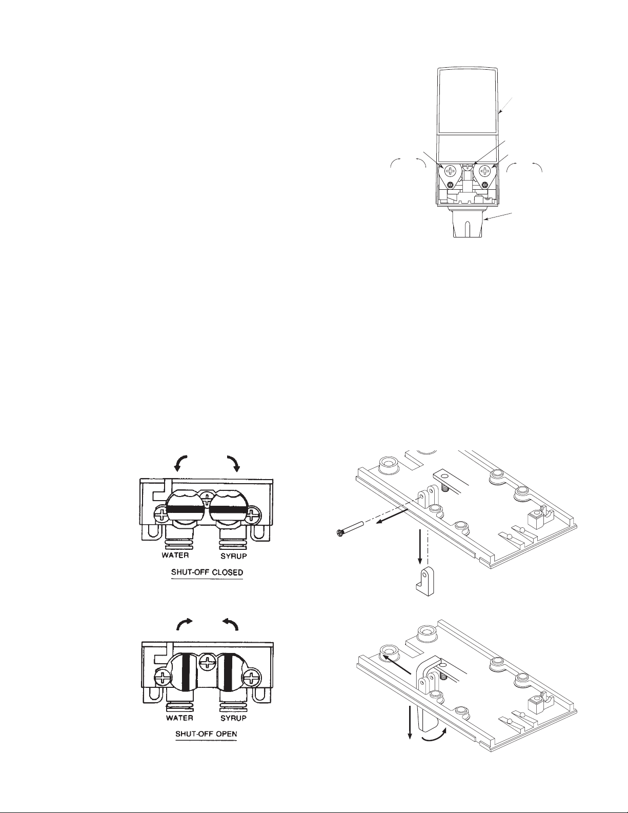
A. Slide I.D. panel up to expose cover mounting screw (see Figure 1).
B. Loosen cover mounting screw (DO NOT REMOVE) and remove cover.
C. Turn both stems on mounting block to the CLOSED position (see Figure 2).
D. Lift up wire retainer and remove mounting block from valve.
E. Replace the inlet water and syrup o-rings on dispenser valve ttings.
F. Lubricate o-rings on the ttings and mounting block with water or an FDA-approved lubricant.
G. If syrup-out light is furnished with valve, run light wires through mounting block and valve plate.
Connect wiring to pressure switch in product line (24 VAC power supply required).
H. Install mounting block to valve plate using four (4) mounting screws removed from existing
mounting block.
I. Install valve on mounting block. Push wire retainer down. This will lock valve to mounting block.
(White stems must be in closed position. See Figure 2.)
J. Turn on carbonator water supply and syrup supply to dispenser.
K. Turn both white stems on mounting block to the OPEN position (see Figure 3). Top of stem will
lock wire retainer in position.
L. If electric version, reconnect to 24 VAC power supply.
M. Operate the valve momentarily to ensure ow of carbonated water and syrup.
NOTE: Model 100 valves are factory preset for a ow rate of 3.0 ounces per second; an adjustment
N. Adjust water ow to correct ow rate (see following instructions).
O. Adjust ratio (oBrix) to correct setting (see following instructions).
P. Install cover on valve and tighten cover mounting screw.
Q. Slide down I.D. panel.
1.4 ADJUSTING WATER FLOW
The water ow for the Model 100 may be adjusted from 1.25 oz/sec (37 ml/sec) to 2.50 oz/sec
(74 ml/sec). The water ow for the Model 145 may be adjusted from 2.0 oz/sec (59.2 ml/sec) to
4.50 oz/sec (133.2 ml/sec). The restricted ow adjustment plug (Model 100) adjusts to a maximum
ow of 2.0 oz/sec (59.2 ml/sec). The restricted ow adjustment plug (Model 145) adjusts to a
maximum ow of 3.3 oz/sec (97.7 ml/sec).
A. Slide up I.D. panel until ow control adjustments are exposed (see Figure 1).
B. Remove nozzle by twisting counter clockwise and pulling down.
C. Remove diffuser by pulling down.
LESIONES.
ATTENTION SI DISTRIBUTEUR EST BRANCHÉE AU COURANT, L’APPAREIL DOIT ÊTRE CORRECTEMENT
TERRE POUR ÉVITER UN CHOC ÉLECTRIQUE MORTEL POSSIBLE OU BLESSURES GRAVES BLESSURES.
may be required. Model 145 valves are factory preset for a ow rate of 4.5 ounces per second; an
adjustment may be required.
4
Page 5
D. Install Lancer syrup separator (yellow) (PN 54-0031 for Model 100 valves) or Lancer syrup
A
B
C
separator (smoke) (PN 54-0201 for Model 145 valves) in place of the nozzle.
E. Activate valve to ll separator syrup tube.
F. Hold a Lancer oBrix cup under syrup separator.
Dispense water and syrup into cup for two (2)
I.D. PANEL
(Shown in
open position)
seconds. Divide number of ounces (ml) of water
in cup by two (2) to determine water ow rate per
second.
G. To obtain desired water ow rate, use a
screwdriver to adjust water ow control (see
Figure 1).
1.5 ADJUSTING WATER TO SYRUP oBRIX
For the Model 100, the syrup ow may be adjusted
from 0.25 oz/sec (7.4 ml/sec) to 0.50 oz/sec
FLOW CONTROL
WATER
DecreaseIncrease
COVER SCREW
FLOW CONTROL
SYRUP
DecreaseIncrease
NOZZLE (WITH
DIFFUSER INSIDE)
(14.8 ml/sec). For the Model 145, the syrup ow may
be adjusted from 0.50 oz/sec (14.8 ml/sec) to 0.90
oz/sec (26.6 ml/sec).
A. Hold the Lancer oBrix cup under the syrup
Typical Valve
Figure 1
separator and activate valve. Check oBrix.
B. To obtain desired oBrix, use screwdriver to adjust syrup ow control (see Figure 1).
C. Remove syrup separator.
D. Install diffuser and nozzle.
E. Slide down I.D. panel.
1.6 INSTALLATION OF SODA LEVER
The soda lever may be eld installed.
A. Remove valve cover.
B. Turn both stems on mounting block to CLOSED position (see Figure 2).
C. Disconnect electric wiring harness.
D. Remove valve from mounting block.
E. Locate bottom plate plug in bottom plate on left side of nozzle (if necessary).
F. Pull out stainless steel pin and remove bottom plate plug (see Figure 4).
Mounting Block Stems in CLOSED Position
Figure 2
Mounting Block Stems in OPEN Position
Figure 3
Figure 4
Figure 5
5
Page 6
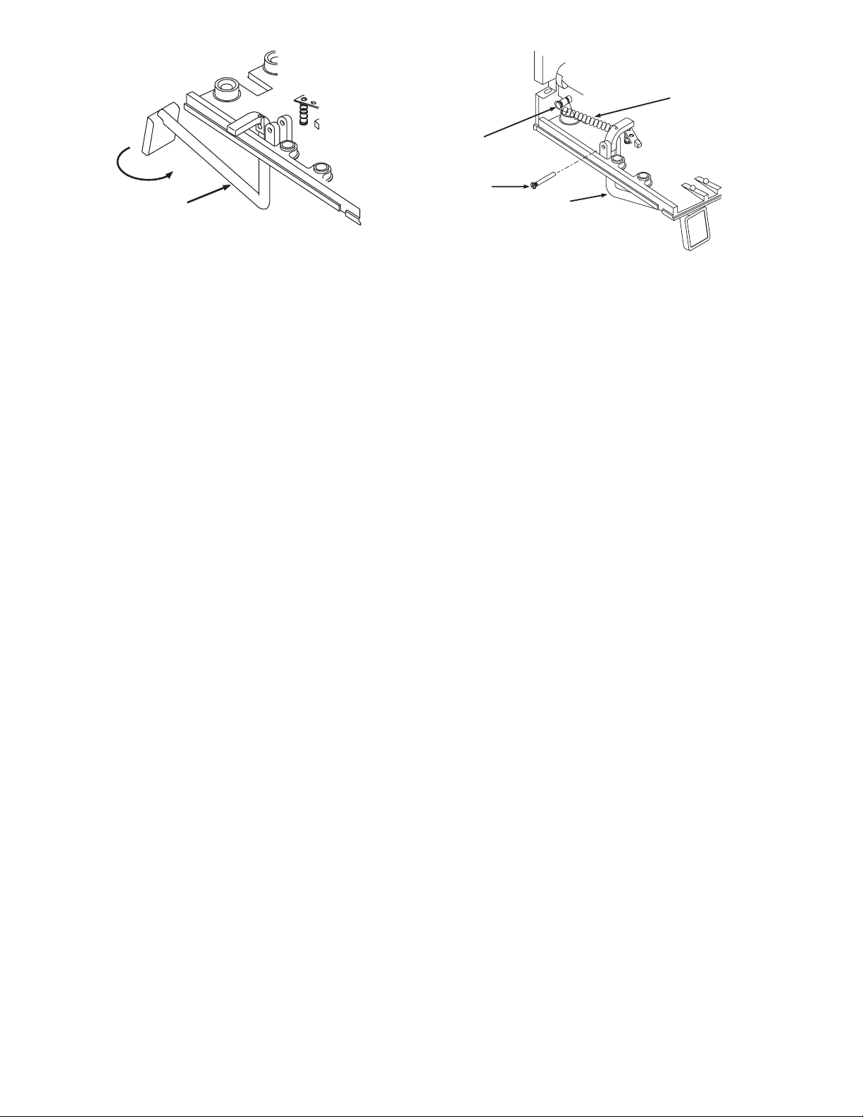
Figure 6 Figure 7
FRONT
SODA/WATER
LEVER
STUD PIN
SPRING
PIN
FRONT
SODA/WATER
LEVER
NOTE: If valve does not have pin, push bottom of plug to snap it out of position.
G. Remove nozzle by twisting counter clockwise and pulling down.
H. Remove diffuser by pulling down.
I. Hold cup lever back and lay soda lever across bottom of valve with small leg extending through
hole. Twist soda lever slightly and bring to upright position. Soda lever will slide between the
vertical supports.
J. Release cup lever.
K. Line up holes in supports and soda lever and install stainless steel pin.
L. Install diffuser and nozzle.
M. Install valve on mounting block and latch wire retainer.
N. Reconnect electric wire harness.
O. Turn both stems on mounting block to OPEN position (see Figure 3).
P. Push soda lever back and check for soda/water ow.
Q. Install cover and tighten cover screw.
R. Slide down I.D. panel.
1.7 REMOVAL AND INSTALLATION OF FRONT SODA/WATER LEVER (KIT PN 82-1458)
A. Slide I.D. panel up to expose cover mounting screw (see Figure 1).
B. Loosen cover mounting screw (DO NOT REMOVE) and remove cover.
C. Close stems on mounting block (see Figure 2).
D. Operate valve to check for complete shutoff of water and syrup.
E. Lift up wire retainer and carefully remove valve from mounting block. Disconnect wire harness.
F. Locate bottom plate plug or soda lever in bottom plate on left side of valve. For removal of
either item, remove pin and retain for reinstallation (see Figure 4).
NOTE: If valve does not have pin, push bottom of plug to snap it out of position.
G. To remove existing soda lever, slide lever behind vertical supports (see Figure 5). Carefully pull
lever down, rotating it towards the back right corner of the bottom plate. Then slide lever out of
the slot.
H. To install the front soda/water lever, rst position the lever so that the contact pad faces towards
the rear of the valve (see Figure 6).
1. Insert the front soda/water lever through the bottom plate and rotate the lever to the left
until the contact pad is facing forward and the extension is positioned over the paddle arm
on the left.
2. To install spring (see Figure 7), press stud pin into hole on upper body and t one end of
spring into outer groove of stud pin. Fit other end of spring into hole on top of front
soda/water lever. Install pin.
I. Install diffuser and nozzle.
J. Install valve on mounting block and latch wire retainer.
K. Reconnect electric wire harness.
L. Turn both stems on mounting block to OPEN position (see Figure 3).
M. Push soda lever back and check for soda/water ow.
N. Attach appropriate label to push pad on front soda/water lever.
O. Install cover and tighten cover screw.
P. Slide down I.D. panel.
6
Page 7

1.8 REMOVAL AND INSTALLATION OF FLOW CONTROLS
SLEEVE
A. Slide I.D. panel up to expose cover mounting screw (see Figure 1).
B. Loosen cover mounting screw (DO NOT REMOVE) and remove cover.
C. Close stems on mounting block (see Figure 2).
D. Operate valve to check for complete shutoff of water and syrup.
E. Remove top screw and loosen bottom screw. Remove retainer.
F. Remove plug adjustment assembly by threading extractor tool (PN 52-1950) into the bonnet
and pulling it out. This will expose the ow control.
G. Lift up wire retainer and carefully remove valve from mounting block. If electric, disconnect wire
harness.
H. Tilt valve forward to remove spring and piston.
NOTE: If piston is going to be reused, use caution when handling.
I. Replace valve to mounting block and
push wire retainer down. This will
provide a stable working condition.
J. To remove sleeve, use ow control
FLOW EXTRACTOR TOOL
extractor tool (PN 52-1950) (see
Figure 8).
RUBBER BUSHING
1. Ensure rubber bushing is loose on
handle.
2. Push rubber bushing into sleeve.
3. Turn clockwise to tighten bushing
inside sleeve.
NOTE: This will allow sleeve to be removed
or installed.
(4) Turn counterclockwise to loosen
bushing inside sleeve. This will
allow tool to be removed from
sleeve.
K. To replace sleeve, place sleeve on ow
control extractor tool (see Figure 8) and
insert in upper body.
Flow Control Extractor Tool
Figure 8
L. Lubricate o-ring with water (or any FDA approved lubricant) and push sleeve to bottom.
M. Reassemble spool, spring, plug adjustment assembly, retainer and screws
N. Turn both shut offs on mounting block to the OPEN position (see Figure 3).
O. Replace cover and tighten mounting screw.
P. Adjust water ow to correct ow rate (refer to Section 1.4).
Q. Adjust oBrix to correct setting (refer to Section 1.5).
R. Slide down I.D. panel.
2. CLEANING
2.1 DAILY CLEANING
A. Nozzle and diffuser must be cleaned daily.
1. Remove nozzle by twisting counter clockwise and pulling down.
2. Remove diffuser by pulling down.
3. Wash nozzle and diffuser with warm water. Ensure that cleaning solution is thoroughly
rinsed from nozzle and diffuser. Residual solution will cause foaming and off taste in
nished product.
4. Reinstall diffuser and nozzle.
NOTE: Ensure compliance with the instructions of the dispenser manufacturer to properly clean
and sanitize the nozzle and diffuser, and ensure no off-taste is present.
2.2 BI-WEEKLY SANITIZING
A. Nozzle and diffuser must be sanitized bi-weekly. Comply with the instructions of the dispenser
manufacturer to properly sanitize the nozzle and diffuser, and ensure no off-taste is present.
7
Page 8
3. SYRUP BRIX CUP
05-0081 Soda Brix Cup 05-0170 Syrup Brix Cup 5.00 to 1
05-0083 Syrup Brix Cup 4.00 to 1 05-0086 Syrup Brix Cup 5.2 to 1
05-0084 Syrup Brix Cup 4.20 to 1 05-0087 Syrup Brix Cup 5.30 to 1
05-0085 Syrup Brix Cup 4.40 to 1 05-0088 Syrup Brix Cup 5.40 to 1
05-0171 Syrup Brix Cup 4.50 to 1 05-0089 Syrup Brix Cup 5.50 to 1
05-0169 Syrup Brix Cup 4.75 to 1 05-0090 Universal Split Cup
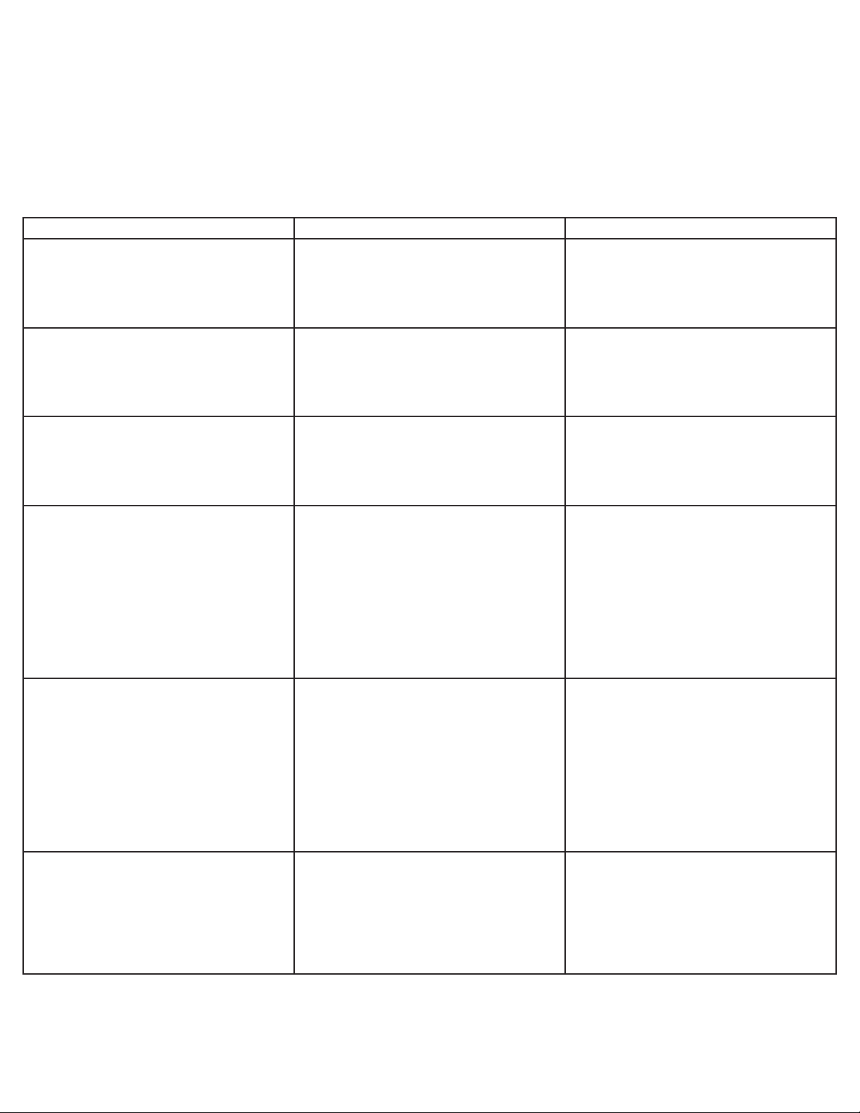
4. TROUBLESHOOTING
TROUBLE CAUSE REMEDY
4.1 Water leakage around nozzle. A. O-ring not properly installed above
diffuser
A. Install or replace o-ring correctly.
B. O-ring is damaged or missing.
4.2 Leakage between upper and lower
bodies.
4.3 Miscellaneous leakage. A. Gap between parts.
4.4 Insufcient water ow. A. Water owing pressure is too low, or
4.5 Insufcient syrup ow. A. Syrup owing pressure is too low, or
A. One or more retaining screws loose.
B. Paddle arm assemblies are worn or
damaged
B. Damaged or improperly installed
o-rings.
restricted
B. Foreign debris in water ow controls.
restricted
B. Replace o-rng.
A. Tighten all six (6) retaining screws.
B. Replace paddle arm assemblies.
A. Tighten appropriate retaining screws
B. Replace or adjust appropriate o-rings
A. 1. Check incoming water from
carbonator to ensure minimum owing
pressure. See SPECIFICATIONS.
2. Check stems on mounting block to
ensure it is in fully OPEN position.
B. Remove water ow control from upper
body and cleanout any foreign materials
to ensure smooth free piston movement.
A. 1. Check incoming syrup to ensure
minimum owing pressure. See
SPECIFICATIONS.
2. Check shutoff on mounting block to
ensure it is in fully OPEN position.
B. Foreign debris in syrup ow controls.
4.6 Erratic Ratio oBrix. A. Incoming water and/or syrup supply
not at sufcient owing pressure.
B. Foreign debris in water and/or syrup
ow controls.
8
B. Remove syrup ow control from upper
body and cleanout any foreign materials
to ensure smooth free piston movement.
A. Check incoming water and syrup
supply to ensure sufcient owing
pressure.
B. Remove ow controls and clean out
any foreign materials to ensure smooth
free piston movement.
Page 9
TROUBLE CAUSE REMEDY
4.7 No product dispensed. A. Water and syrup shutoffs are not fully
OPEN.
A. Check stems on mounting block to
ensure they are in fully OPEN position.
B. Ensure cup lever arm, or I.D. Panel
actuator is actuating switch.
C. Electric current is not reaching valve.
D. Improper or inadequate water or syrup
supply.
4.8 Water only dispensed, no syrup; or
syrup only dispensed, no water.
4.9 Valve will not shut off. A. Cup Lever may be sticking or binding
A. Water or syrup stem on mounting
block not fully OPEN.
B. Improper or inadequate water or syrup
supply.
B. If not, repair or replace.
C. Check electric current supplied to
valve. See SPECIFICATIONS. If current is adequate, check solenoid coil and
switch. Replace if necessary.
D. Remove valve from mounting block
and open stems slightly and check to
ensure proper water and syrup supply. If
no supply, check dispenser for freeze-up
or other problems.
A. Check stems on mounting block to
ensure they are in full OPEN position.
B. Remove valve from mounting block
and open stem slightly to check for
proper syrup and water supply. If no
supply, check dispenser for freeze-up or
other problems.
A. Correct or replace lever.
B. Switch not actuating properly.
C. Solenoid armature not returning to
bottom position.
D. Debris or damage to Paddle arms.
4.10 Excessive Foaming A. Incoming water or syrup temperature
too high.
B. Water ow rate too high.
C. Nozzle and diffuser not clean.
D. Nozzle and diffuser not properly
installed.
E. CO2 pressure too high.
4.11 No syrup-out light. (If equipped.) A. Burned out or defective lamp.
B. Faulty wiring and/or pressure switch in
product line.
B. Check switch for free actuation.
C. Replace defective solenoid armature
or spring.
D. Remove debris and/or replace
damaged paddle arms.
A. Correct at dispenser.
B. Readjust and reset Brix. See Section
1.5.
C. Remove and clean.
D. Remove and install properly.
E. Check for proper pressure setting.
A. Replace harness.
B. Repair or replace.
9
Page 10
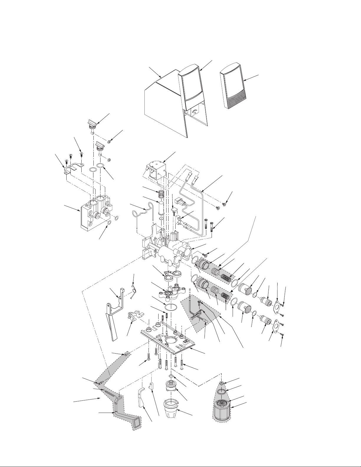
5. ILLUSTRATIONS AND PARTS LISTINGS
5.1 LEV® (MODEL 100L, 3.0 OZ/SEC AND MODEL 145L, 4.5 OZ/SEC)
1
2
3
4
6
1a
7
8
Front Soda/Water
Lever Kit,
PN 82-1458
44
45
48
22
36
33
38
17
5
39
40
41
9
42
12
26
35
16
27
28
10
16
14
18
13
11
14
43
Flow Control, 3.0, Syrup, Kit,
PN 82-1027
Flow Control, 4.5, Syrup, Kit,
PN 82-2226
Flow Control, 3.0, Soda, Kit,
PN 82-1026
Flow Control, 4.5, Soda, Kit,
15
PN 82-2227
19
16
21
22
23
24
25
20
16
21
22
37
30
17a
11
29
47
46
Syrup-Out Light
Kit Option
PN 82-0783
23
24
25
51
52
32
31
50
34
53
Nozzle Assembly, 4.5,
Kit PN 82-2014
49
10
Page 11

5.1 LEV® (MODEL 100L, 3.0 OZ/SEC AND MODEL 145L, 4.5 OZ/SEC) (CONTINUED)
Item Part No. Description
1 05-0287 I.D. Panel
1a 54-0057 I.D. Panel (Syrup-Out)
2 54-0029 Cover Sub Assy
– 54-0030 Cover Assy (Item No. 1-2)
– 54-0059 Cover Assy (Item No. 1a-2)
3 05-0266 Stem, Valve, Mounting Block
4 05-0267 Washer
5 02-0047 O-Ring
6 04-0269 Screw
7 03-0087 Retainer, Stem, Valve,
Mounting Block
8 05-0265 Mounting Block
– 82-0274 Block Assy, Mounting
(Item No. 3-8, 22)
9 03-0233 Retainer, Valve, 1-Piece
10 03-0143 Spring, Pin, LEV®
11 04-0270 Screw
12 54-0189 Body Assy, Upper
13 04-0302 Screw
14 81-0274 Sleeve, Syrup/Water, 3.0
- 81-0382 Sleeve, Syrup/Soda, 4.5
15 81-0273 Piston, Syrup, 3.0
- 81-0383 Piston, Syrup, 4.5
16 02-0132 O-Ring
17 52-0622 Wire Harness
17a 52-0902 Wire Harness (Syrup-Out)
18 81-0275 Piston, Soda, 3.0
- 81-0384 Piston, Soda, 4.5
19 03-0169 Spring, Syrup, Flow Control,
LEV®
20 03-0171 Spring, Soda, Flow Control,
LEV®
21 05-0262 Bonnet, Flow Control
22 02-0126 O-Ring
23 05-1919 Plug, Adjustment,
Flow Control, White
– 82-0527/01 Plug, Adjustment Assy, White
(Item No. 16, 21-23)
24 03-0088 Retainer, Flow Control
25 04-0267 Screw
26 82-2929 Arm, Paddle, Assy
27 54-0046 Body Assy, Lower, 3.0
- 54-0188 Body Assy, Lower, 4.5
28 02-0408 O-Ring, Nozzle, Red, 3.0
(Used in Valves produced
through September 1998)
29 05-0232 Plate, Bottom, 3.0
- 05-1108 Plate, Bottom, 4.5
30 04-0310 Screw
31 02-0133 O-Ring (Used in Valves
produced through
September 1998)
32 05-0281 Plug, Bottom Plate
33 04-0775 Pin, Lever, Soda
Item Part No. Description
34 05-0233 Nozzle, 3.0 (Used in Valves
produced through
September 1998)
- 05-1463 Nozzle, 3.0 (Used
in Valves produced in
September 1998 and later)
35 03-0081 Lever, Spring, Electric
36 05-0231 Lever, Electric
37 05-0238 Yoke, Electric
38 52-0288 Coil Assy,LEV®
39 03-0125 Spring, Solenoid, LEV®
40 10-0117 Armature, LEV®
41 05-0935 Plug, Retainer, Micro-Switch
42 26-0265 Micro-Switch
43 04-0486 Screw
44 04-0724 Pin, Stud
45 03-0238 Spring, Front Soda/Water
Lever
46 05-0490 Holder
47 04-0470 Screw
48 09-0120 Lever, Front, Soda/Water
49 05-0274 Lever, Soda, 3.0
50 54-0028 Diffuser Assy, 3.0 (Used
in Valves produced
through September 1998)
- 05-1593 Diffuser Assy, 3.0 (Used
in Valves produced in
September 1998 and later)
51 02-0133 O-Ring
52 02-0421 Seal, Nozzle, 4.5
53 54-0183 Nozzle Assy, 4.5
11
Page 12

5.2 LEV® WITH SELF-SERVE LEVER
(MODEL 100SSL, 3.0 OZ/SEC AND MODEL 145SSL, 4.5 OZ/SEC)
1
2
3
4
6
38
5
1a
7
8
Front Soda/Water
Lever Kit, PN 82-1458
45
46
42
16
41
17
12
13
14
43
Flow Control, 3.0, Syrup,
Kit, PN 82-1027
Flow Control, 4.5, Syrup,
11
Kit, PN 82-2226
15
19
16
Flow Control, 3.0, Soda,
Kit, PN 82-1026
Flow Control, 4.5, Soda,
Kit, PN 82-2227
39
40
9
22
35
26
21
22
23
24
10
27
28
26
16
14
18
36
P
U
S
H
20
16
37
29
33
30
11
21
22
47
48
17a
Syrup-Out Light
Kit Option
23
24
25
PN 82-0783
31
50
51
52
44
49
32
34
Nozzle Assembly, 4.5,
Kit PN 82-2014
53
12
Page 13

5.2 LEV® WITH SELF-SERVE LEVER
(MODEL 100SSL, 3.0 OZ/SEC AND MODEL 145SSL, 4.5 OZ/SEC) (CONTINUED)
Item Part No. Description
1 05-0287 I.D. Panel
1a 54-0057 I.D. Panel (Syrup-Out)
2 54-0029 Cover Sub Assy
– 54-0030 Cover Assy (Item No. 1-2)
– 54-0059 Cover Assy (Item No. 1a-2)
3 05-0266 Stem, Valve, Mounting Block
4 05-0267 Washer
5 02-0047 O-Ring
6 04-0269 Screw
7 03-0087 Retainer, Stem, Valve,
Mounting Block
8 05-0265 Mounting Block
– 82-0274 Block Assy, Mounting
(Item No. 3-8, 22)
9 03-0233 Retainer, Valve, 1-Piece
10 03-0143 Spring, Pin,LEV®
11 04-0270 Screw
12 54-0189 Body, Upper, Assy
13 04-0302 Screw
14 81-0274 Sleeve, Syrup/Water, 3.0
- 81-0382 Sleeve, Syrup/Soda, 4.5
15 81-0273 Piston, Syrup, 3.0
- 81-0383 Piston, Syrup, 4.5
16 02-0132 O-Ring
17 52-0622 Wire Harness
17a 52-0902 Wire Harness (Syrup-Out)
18 81-0275 Piston, Soda, 3.0
- 81-0384 Piston, Soda, 4.5
19 03-0169 Spring, Syrup, Flow
Control, LEV®
20 03-0171 Spring, Soda, Flow
Control, LEV®
21 05-0262 Bonnet, Flow Control
22 02-0126 O-Ring
23 05-1919 Plug, Adjustment,
Flow Control, White
– 82-0527/01 Plug, Adjustment Assy, White
(Item No. 16, 21-23)
24 03-0088 Retainer, Flow Control
25 04-0267 Screw
26 82-2929 Arm, Paddle, Assy
27 54-0046 Body Assy, Lower, 3.0
- 54-0188 Body Assy, Lower, 4.5
28 02-0408 O-Ring, Nozzle, Red, 3.0
(Used in Valves produced
through September 1998)
29 05-0232 Plate, Bottom,3.0
- 05-1108 Plate, Bottom, 4.5
30 04-0310 Screw
31 02-0133 O-Ring (Used in Valves
produced through
September 1998)
32 05-0281 Plug, Bottom Plate
Item Part No. Description
34 05-0233 Nozzle, 3.0 (Used in Valves
produced through
September 1998)
- 05-1463 Nozzle, 3.0 (Used
in Valves produced in
September 1998 and later)
35 03-0081 Lever, Spring, Electric
36 54-0165 Lever, Self-Serve
37 05-0238 Yoke, Electric
38 52-0288 Coil Assy
39 03-0125 Spring, Solenoid
40 10-0117 A rmature
41 05-0935 Plug, Retainer, Micro-Switch
42 26-0265 Micro-Switch
43 04-0486 Screw
44 09-0120 Lever, Front Soda/Water
45 04-0724 Pin, Stud
46 03-0238 Spring, Front Soda/Water
Lever
47 04-0470 Screw
48 05-0490 Holder
49 05-0274 Lever, Soda, 3.0
50 54-0028 Diffuser Assy, 3.0 (Used
in Valves produced
through September 1998)
- 05-1593 Diffuser Assy, 3.0 (Used
in Valves produced in
September 1998 and later)
51 02-0133 O-Ring
52 05-0421 Seal, Nozzle, 4.5
53 54-0183 Nozzle Assy, 4.5
13
Page 14

5.3 LEV® PUSHBUTTON (Model 100P, 3.0 oz/sec and Model 145P, 4.5 oz/sec)
3
4
36
6
7
5
37
38
8
9
22
40
11
39
12
13
14
15
19
16
16
21
22
23
24
26
Syrup-Out Light
Kit, Option, PN 82-0783
17
35
14
18
20
16
21
22
23
24
25
28
27
26
40a
43
42
41
PUSH
45
10
30
11
31
34
32
29
33
46
44
48
47
Front Soda/Water Lever
Kit, PN 82-1458
Flow Control, 3.0, Syrup,
Kit, PN 82-1027
Flow Control, 4.5, Syrup,
Kit, PN 82-2226
Flow Control, 3.0, Soda,
Kit, PN 82-1026
Flow Control, 4.5, Soda,
Kit, PN 82-2227
1
2
16
Nozzle Assembly Kit, 4.5
PN 82-2014
49
50
51
14
Page 15

5.3 LEV® PUSHBUTTON (Model 100P, 3.0 oz/sec and Model 145P, 4.5 oz/sec) (CONTINUED)
Item Part No. Description
1 54-0140 I.D. Panel, Large Pushbutton
2 54-0029 Cover Sub Assy
– 54-0139 Cover Assy, Large
(Pushbutton, Item No. 1-2)
3 05-0266 Stem, Valve, Mounting Block
4 05-0267 Washer
5 02-0047 O-Ring
6 04-0269 Screw
7 03-0087 Retainer, Stem, Valve,
Mounting Block
8 05-0265 Mounting Block
– 82-0274 Block Assy, Mounting
(Item No. 3-8, 22)
9 03-0233 Retainer, Valve, 1-Piece
10 03-0143 Spring, Pin
11 04-0270 Screw
12 54-0189 Body Assy, Upper
13 04-0302 Screw
14 81-0274 Sleeve, Syrup/Water, 3.0
- 81-0382 Sleeve, Syrup/Soda, 4.5
15 81-0273 Piston, Syrup, 3.0
- 81-0383 Piston, Syrup, 4.5
16 02-0132 O-Ring
17 05-0491 Filler
18 81-0275 Piston, Soda, 3.0
- 81-0384 Piston, Soda, 4.5
19 03-0169 Spring, Syrup,
Flow Control, LEV®
20 03-0171 Spring, Soda,
Flow Control, LEV®
21 05-0262 Bonnet, Flow Control
22 02-0126 O-Ring
23 05-1919 Plug, Adjustment,
Flow Control, White
– 82-0527/01 Plug, Adjustment Assy, White
24 03-0088 Retainer, Flow Control
25 04-0267 Screw
26 82-2929 Arm, Paddle, Assy
27 54-0046 Body Assy, Lower, 3.0
- 54-0188 Body Assy, Lower, 4.5
28 02-0408 O-Ring, Nozzle, Red, 3.0
(Used in Valves produced
through September 1998)
29 05-0232 Plate, Bottom, 3.0
- 05-1108 Plate, Bottom, 4.5
30 04-0310 Screw
31 02-0133 O-Ring (Used in Valves
produced through
September 1998)
32 05-0281 Plug, Bottom Plate
33 04-0775 Pin, Lever, Soda
34 05-0233 Nozzle, 3.0 (Used in Valves
produced through
September 1998)
- 05-1463 Nozzle, 3.0 (Used
in Valves produced in
September 1998 and later)
Item Part No. Description
35 05-0238 Yoke, Electric
36 52-0288 Coil Assy, LEV®
37 03-0125 Spring, Solenoid, LEV®
38 10-0117 Armature, LEV®
39 04-0486 Screw
40 52-0622 Wire Harness
40a 52-0902 Wire Harness (Syrup-Out)
41 04-0470 Screw
42 05-0490 Holder
43 26-0265 Micro-Switch
44 09-0120 Lever, Front Soda/Water
45 04-0724 Pin, Stud
46 03-0238 Spring, Front Soda/Water
Lever
47 05-0274 Lever, Soda
48 54-0028 Diffuser Assy, 3.0 (Used
in Valves produced
through September 1998)
- 05-1593 Diffuser Assy, 3.0 (Used
in Valves produced in
September 1998 and later)
49 02-0133 O-Ring
50 02-0421 Seal, Nozzle, 4.5
51 54-0183 Nozzle Assy, 4.5
15
Page 16

5.4 LEV® SUREFILL (MODEL 100SF, 3.0 OZ/SEC AND MODEL 145SF, 4.5 OZ/SEC)
10
1
21
20
11
3
12
2
13
4
6
14
5
15
36
33
48
36
37
49
37
38
47
39
40
Flow Control, 3.0, Syrup, Kit,
PN 82-1027
Flow Control, 4.5, Syrup, Kit,
PN 82-2226
Flow Control, 3.0, Soda, Kit,
PN 82-1026
Flow Control, 4.5, Soda, Kit,
PN 82-2227
41
42
56
44
57
45
46
7
18
16
17
8
9
22
35
34
35
32
42
43
44
57
45
46
23
19
31
24
30
25
26
27
53
28
29
50
51
54
55
Nozzle Assembly, 4.5,
Kit PN 82-2014
52
Front Soda/Water Lever Kit, PN 82-1458
16
Page 17

5.4 LEV® SUREFILL (MODEL 100SF, 3.0 OZ/SEC AND MODEL 145SF, 4.5 OZ/SEC) (CONTINUED)
Item Part No. Description
1 05-0287 I.D. Panel
2 54-0029 Cover Sub Assy
– 54-0030 Cover Assy (Item No. 1-2)
3 05-0266 Stem, Valve, Mounting Block
4 05-0267 Washer
5 02-0047 O-Ring
6 04-0269 Screw
7 03-0087 Retainer, Stem, Valve,
Mounting Block
8 05-0265 Mounting Block
– 82-0274 Block Assy, Mounting
(Item No. 3-9)
9 02-0126 O-Ring
10 04-0478 Screw
11 30-7245 Strap
12 82-1982 Module, Surell
13 04-0270 Screw
14 05-0788 Module Bracket (Used in
Valves produced through
September 2000)
- 05-1928 Bracket, PCB, White (Used
in Valves produced in
October 2000 and later)
15 52-0288 Coil Assy, LEV®
16 03-0125 Spring, Solenoid, LEV®
17 10-0117 Armature, LEV®
18 03-0233 Retainer, Valve, 1-Piece
19 04-0724 Pin, Stud
20 05-0777 Bushing, Lever
21 30-5416 Lever
22 04-0642 Screw, 6 - 32 x 0.250
23 05-0238 Yoke, Electric
24 04-0775 Pin, Lever, Soda
25 04-0310 Screw
26 03-0238 Spring, Front Soda/Water
Lever
27 09-0120 Lever, Front Soda/Water
28 05-0274 Lever, Soda
29 05-0281 Plug, Bottom Plate
30 04-0270 Screw
31 05-0801 Plate, Bottom, 3.0
- 05-1544 Plate, Bottom, 4.5
32 03-0143 Spring, Pin
33 02-0408 O-Ring, Nozzle, Red, 3.0
(Used in Valves produced
through September 1998)
34 54-0046 Body Assy, Lower, 3.0
- 54-0188 Body Assy, Lower, 4.5
35 82-2929 Arm, Paddle, Assy
36 02-0132 O-Ring
37 81-0274 Sleeve, Syrup/Soda, 3.0
Item Part No. Description
- 81-0382 Sleeve, Syrup/Soda, 4.5
38 81-0275 Piston, Soda, 3.0
- 81-0384 Piston, Soda, 4.5
39 81-0273 Piston, Syrup, 3.0
- 81-0383 Piston, Syrup, 4.5
40 03-0171 Spring, Soda, Flow Control,
LEV®
41 03-0169 Spring, Syrup, Flow Control,
LEV®
42 02-0132 O-Ring
R 43 05-0796 Bonnet, Surell, Black
44 02-0126 O-Ring
45 03-0088 Retainer
46 04-0267 Screw
47 04-0302 Screw
48 54-0189 Body Assy, Upper
49 04-0486 Screw
50 02-0133 O-Ring (Used in Valves
produced through
September 1998)
51 54-0028 Diffuser Assy, 3.0 (Used
in Valves produced
through September 1998)
- 05-1593 Diffuser Assy, 3.0 (Used
in Valves produced in
September 1998 and later)
52 05-0233 Nozzle, 3.0 (Used in
Valves produced through
September 1998)
- 05-1463 Nozzle, 3.0 (Used
in Valves produced in
September 1998 and later)
53 02-0133 O-Ring
54 02-0421 Seal, Nozzle, 4.5
55 54-0183 Nozzle Assy, 4.5
R 56 05-0262 Bonnet, Flow Control, Red
57 05-1919 Plug Adjust, Flow Control,
White Sub Assemblies
Available
R - 82-2992 Plug Adjust Assy, Soda
(Items 42, 43, and 44)
R - 82-0527 Plug Adjust Assy, Syrup
(Items 42, 43, and 44)
R in margin indicates revision or data change
17
Page 18

5.5 LEV® PORTION CONTROL (MODEL 100PC, 3.0 OZ/SEC AND MODEL 145PC, 4.5 OZ/SEC)
1
2
3
4
6
36
7
8
Front Soda/Water Lever
Kit, PN 82-1458
44
22
35
33
17
5
39
37
9
Flow Control, 3.0, Syrup,
11
Kit, PN 82-1027
Flow Control, 4.5, Syrup,
38
12
16
13
14
Kit, PN 82-2226
Flow Control, 3.0, Soda,
Kit, PN 82-1026
Flow Control, 4.5, Soda,
Kit, PN 82-2227
15
19
26
16
21
22
23
24
27
28
10
26
16
14
18
20
16
21
30
29
41
42
40
Syrup-Out Light Kit,
Option, PN 82-2131
22
23
24
25
11
45
43
46
32
18
31
47
34
48
49
Nozzle Assembly Kit, 4.5
PN 82-2014
50
Page 19

5.5 LEV® PORTION CONTROL (MODEL 100PC, 3.0 OZ/SEC AND MODEL 145PC, 4.5 OZ/SEC)
(CONTINUED)
Item Part No. Description
1 52-1581 I.D. Panel (Used in Valves
produced through May 2000)
- 52-2296 I.D. Panel, PC, Parylene
(Used in Valves produced
through June 2000 and later)
2 54-0029 Cover Sub Assy
– 54-0181 Cover Assy, Large (Items No.
1-2)
3 05-0266 Stem, Valve, Mounting Block
4 05-0267 Washer
5 02-0047 O-Ring
6 04-0269 Screw
7 03-0087 Retainer, Stem, Valve,
Mounting Block
8 05-0265 Mounting Block
– 82-0274 Block Assy, Mounting
(Item No. 3-8, 22)
9 03-0233 Retainer, Valve, 1-Piece
10 03-0143 Spring, Pin
11 04-0270 Screw
12 54-0189 Body Assy, Upper
13 04-0302 Screw
14 81-0274 Sleeve, Syrup/Water, 3.0
- 81-0382 Sleeve, Syrup/Soda, 4.5
15 81-0273 Piston, Syrup, 3.0
- 81-0383 Piston, Syrup, 4.5
16 02-0132 O-Ring
17 05-0491 Filler
18 81-0275 Piston, Soda, 3.0
- 81-0384 Piston, Soda, 4.5
19 03-0169 Spring, Syrup, Flow Control,
LEV®
20 03-0171 Spring, Soda, Flow Control,
LEV®
21 05-0262 Bonnet, Flow Control
22 02-0126 O-Ring
23 05-1919 Plug, Adjustment, Flow
Control, White
– 82-0527/01 Plug, Adjustment Assy, White
24 03-0088 Retainer, Flow Control
25 04-0267 Screw
26 82-2929 Arm, Paddle, Assy
27 54-0046 Body Assy, Lower, 3.0
- 54-0188 Body Assy, Lower, 4.5
28 02-0408 O-Ring, Nozzle, Red, 3.0
(Used in Valves produced
through September 1998)
Item Part No. Description
29 05-0232 Plate, Bottom, 3.0
- 05-1108 Plate, Bottom, 4.5
30 04-0310 Screw
31 02-0133 O-Ring (Used in Valves
produced through September
1998)
32 05-0281 Plug, Bottom Plate
33 04-0775 Pin, Lever, Soda
34 05-0233 Nozzle, 3.0 (Used in Valves
produced through
September 1998)
- 05-1463 Nozzle, 3.0 (Used in Valves
produced in September 1998
and later)
35 05-0238 Yoke, Electric
36 52-0288 Coil Assy, LEV®
37 03-0125 Spring, Solenoid, LEV®
38 10-0117 Armature, LEV®
39 04-0486 Screw
40 52-2069 Wire Harness (Syrup-Out)
41 04-0470 Screw
42 05-0490 Holder
43 09-0120 Lever, Front Soda/Water
44 04-0724 Pin, Stud
45 03-0238 Spring, Front Soda/Water
Lever
46 05-0274 Lever, Soda
47 54-0028 Diffuser Assy, 3.0 (Used in
Valves produced through
September 1998)
- 05-1593 Diffuser Assy, 3.0 (Used in
Valves produced in
September 1998 and later)
48 02-0133 O-Ring
49 02-0421 Seal, Nozzle, 4.5
50 54-0183 Nozzle Assy, 4.5
6. APPLIANCE DISPOSAL
To prevent possible harm to the environment from improper disposal, recycle the unit
by locating an authorized recycler or contact the retailer where the product was pur
chased. Comply with local regulations regarding disposal of the refrigerant and
insulation.
19
Page 20

Lancer Corp.
800-729-1500
Technical Support/Warranty: 800-729-1550
custserv@lancercorp.com
lancercorp.com
 Loading...