

Page 1
Product Catalog
Packaged Gases
Ensuring cryogenic supply capabilities.
Any application - Any time
Page 2
Ensuring cryogenic supply capabilities. Any application - Any time
Production Facility
Canton, Georgia
Packaged Gases Advantage
Chart’s Packaged Gases are engineered and manufactured to the highest quality standards to
provide you with the safest and most reliable equipment available. Driven by innovation, our
patented cylinder support system and Liquid Cylinder Control Manifold (LCCM) revolutionized the
industry. Experience from understanding our customer’s specifications and the end-use applications
has made Chart the standard in the industry. When you want the best in packaged gases equipment,
our wide range of products are certain to satisfy your requirements while providing the lowest cost
of ownership.
Engineering Design
Our Packaged Gases equipment designs are
based on integrating patented and proven
innovative technologies. Every component
is engineered, built and tested to create
the safest and most reliable Packaged
Gases equipment available today.
Quality Manufacturing
Our experience and code compliant ISO
9001 ensures our liquid cylinders are
completed to high quality standards and
on time.
Performance
The patented Dura-Cyl design is the
perfect blend of plumbing controls,
rugged durability and thermal efficiency —
giving you the highest performance liquid
cylinder package on the market today.
When you choose Chart, you get single-source accountability
2
from initial quality through after the sale service support.
Page 3
Packaged Gases
How We Build the Best Liquid Cylinder
Simply stated, innovation is the foundation of Chart’s legendary performance, lowest life-cycle cost,
safety, and user-friendliness. Each of Chart’s world-leading liquid cylinders has been developed with
a commitment to quality, precision engineering and technical excellence.
LCCM
The patented Liquid Cylinder Control
Manifold (LCCM) reduces plumbing
connections by combining the Economizer
Handling Ring
Large diameter heavy-gauge stainless
steel rolled ring supported with four
brackets for additional strength. Plumbing,
gauges and control valves are well
protected when exposed to rough handling.
Neck Tube
Our rugged neck tube is a key component
to our patented Dura-Series support system
design. It is a perfect balance of low heat
loss and durability in event of a tip-over.
and Pressure Builder (PB) regulator along
with the PB isolation valve. The set
pressure can easily be adjusted by hand
with the calibrated dome control knob.
Load Ring
The load ring is another key component
to our patented Dura-Series support system
design. In the event of a tip-over, the
shock is distributed from the outer shell
to the inner vessel through the load ring.
This helps prevent failure of the neck
tube and gives protection in all directions.
Outer Shell
Our high-strength high-polish stainless
steel outer shell is a full 12-gauge thickness
for maximum dent resistance for a longer
life quality appearance.
Bottom Support
Another key component to our patented
Dura-Series support system. The bottom
support not only supports the inner vessel
in the event of a tip-over, but this unique
design prevents the outer top head from
caving if the cylinder is dropped vertically.
Footring
Our footring is made of thick 7-gauge
stainless steel and welded 100% to the
bottom head. This all metal, boltless
design helps absorb vertical shock,
promotes cylinder stability and eliminates
maintenance over the cylinder’s life.
Vacuum & Insulation
Reducing heat transfer from the inner
vessel has always been our top priority.
That’s why we integrate a proprietary spiral
wrap super insulation system with our
vacuum maintenance system. This durable
proven package will give you years of troublefree service for maximum NER performance.
Inner Vessel
Every step in design, engineering, fabrication
and inspection is directed toward meeting
DOT 4L, TC4LM and other pressure vessel
codes and specifications.
Vaporizer
We optimize our vaporizer designs with
the available area of the outer shell to
yield the highest gas withdrawal rates
attainable. During the manufacturing
process, we solder the copper coils to the
inside of the outer shell with custom robotic
machines to maximize the solder content
and control the bonding strength to
achieve our high performance specifications.
3
Page 4
Ensuring cryogenic supply capabilities. Any application - Any time
Packaged Gases Meet the Needs of Any Application
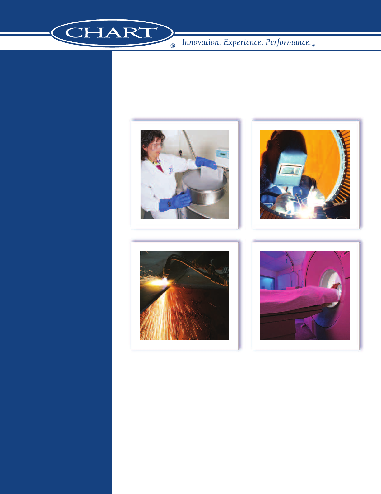
Welding - GMAW/MIG, GTAW/TIG and Laser Beam Welding
etal fabrication uses many different welding processes for the wide range
M
of materials, thicknesses and product applications. Many of these unique and
specialized welding processes use inert shielding gas or the combination of
gases to obtain maximum weld quality with optimized productivity. Liquid
cylinders offer the flexibility to easily alter the gas supply to match the
manufacturing process changes.
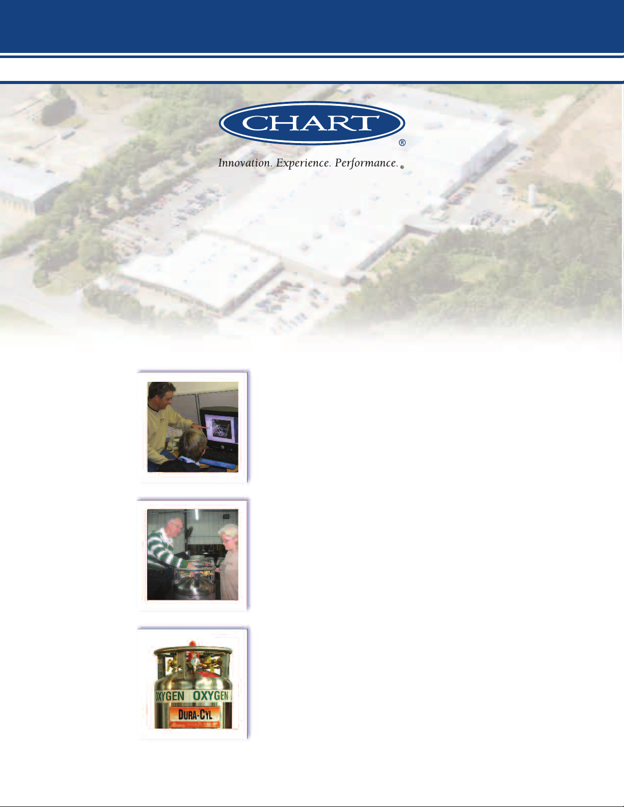
Cutting – Laser, Oxy Fuel and Plasma
All thermal cutting techniques utilize gases to assist in the cutting process.
High-pressure nitrogen and oxygen are used as an assist gas to rapidly remove the
Metal Fabrication
molten metal from the cut zone or burn it away during the laser cutting process.
To maintain maximum laser uptime and achieve the best cut quality, it is critical
that the gas supply be uninterrupted and the required pressures and flows for the
material and thickness being cut are maintained. Oxy Fuel and Plasma cutting
processes have similar requirements. Laser-Cyl liquid cylinders manifolded together
are an economical solution to providing an uninterrupted gas supply.
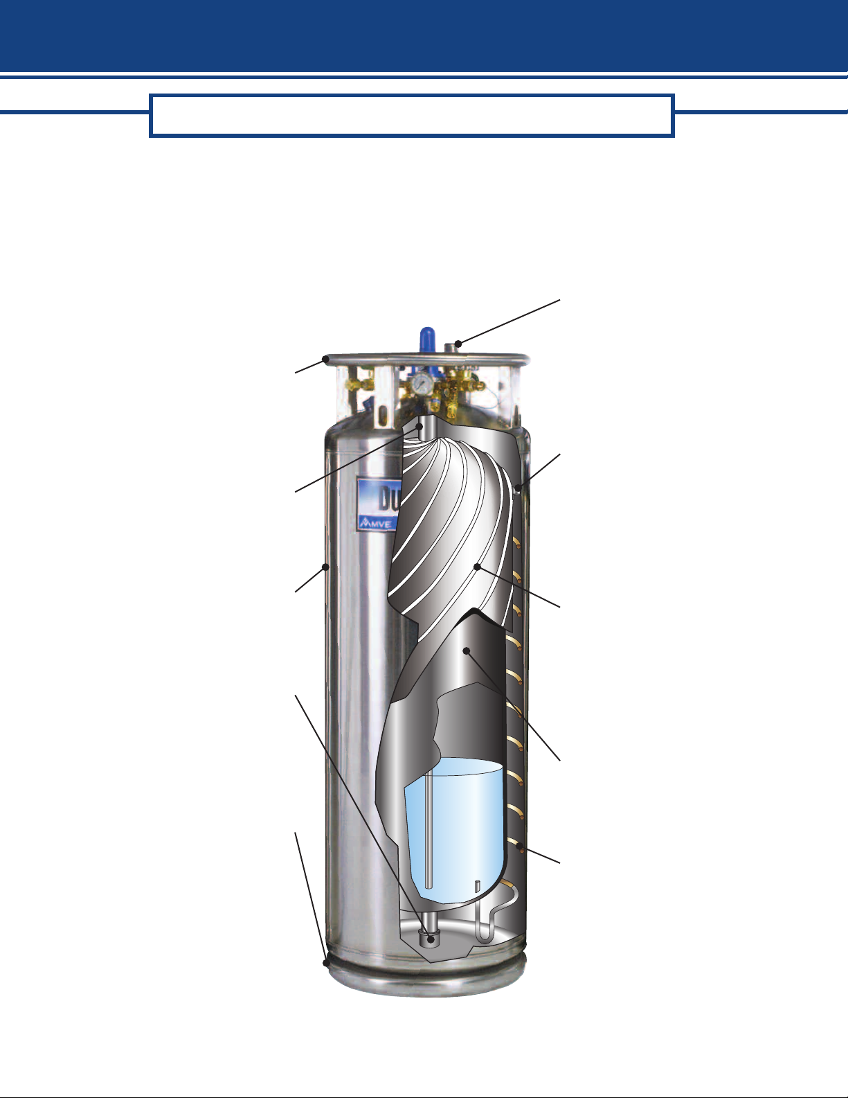
Analytical / Laboratory Metal Processing
Heat Treating • Cryotempering • Thermal Spray Coating
Heat treating and cryotempering processes are dependent on the quality of
the nitrogen gas and liquid supply to maintain production at peak performance.
With the Dura-Cyl located at the point of use, the operator has complete
control over their gas supply for optimum operation. In the thermal spray
coating process, oxygen and argon are used at high pressure and at high flow
rates. Manifolding Dura-Cyl tanks together is an economical solution for
this application.
ICP/ICP-MS – Inductively Coupled Plasma/Mass Spectrometry
GC – Gas Chromatograph
A continuous flow of high purity argon gas is required for ICP/ICP-MS systems to
repeatedly process material samples trouble-free. Dura-Cyl liquid cylinders
manifolded together meet this requirement. In addition, liquid cylinders are
compact so they take up a minimal amount of valuable lab space.
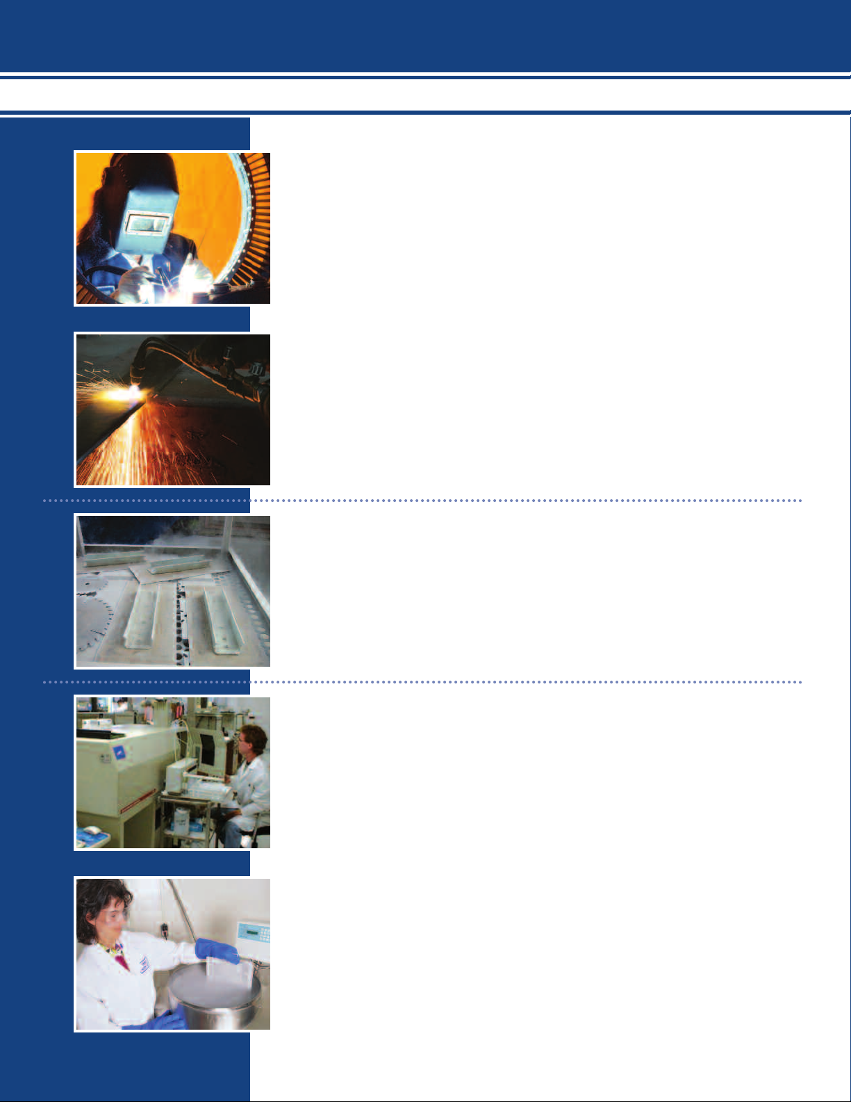
Biological Storage and Research
A sufficient supply of high-quality liquid nitrogen is needed to keep valuable
biological samples stored indefinitely. Any interruption in supply can result in
the loss of many years of research. With dedicated Dura-Cyl liquid cylinders
connected to your equipment, you can be assured of your liquid supply to keep
your samples safe. For applications that require the greatest amount of liquid
in a tight space, the Dura-Cyl 265 with casters is an excellent choice.
4
Page 5
Packaged Gases
MRI - Magnetic Resonance Imaging (Helium)
Superconducting magnets bathed in liquid helium are the most commonly
used magnets in an MRI machine. The low temperature reduces the internal
resistance to zero, which reduces the electrical requirement for the system
dramatically and making it much more economical to operate. Chart’s Ultra
Helium Dewars are designed and built for reliable helium transport. They are
thermally efficient, lightweight and maneuverable – making them the dewar
of choice of lab personnel.
Medical
Oxygen Therapy • Cryotherapy
Medical applications have some of the most stringent gas specifications and
the Dura-Cyl meets these requirements with NF grade availability. Dura-Cyls
manifolded together for respiratory therapy assures a continuous gas supply
and lowers distribution costs over high pressure cylinders. An isolated hyperbaric
chamber with intermittent use of oxygen is also a good application for Dura-Cyls.
NF grade nitrogen can also be supplied for gas applications to operate pneumatic
surgical tools and supply liquid for medical uses such as cryotherapy.
General Processing
Purging and Blanketing
Inert purging and blanketing with nitrogen or argon gas is a common processing
step in many manufacturing applications. These range from pharmaceutical to
chemical to wine making. Other unique applications like keeping fiber optic and
telephone wire lines dry with nitrogen throughout the city make the Dura-Cyl an
excellent choice of inert gas supply.
Electronic Manufacturing and Testing
Electronics manufacturing can use liquid or gaseous nitrogen or argon during the
manufacturing process. Dura-Cyl liquid cylinders offer a compact package where
the pressure and source is near the operation for convenience and customization
of the gas supply. In a related business, printed circuit board testing (HALT/HASS)
performed with liquid nitrogen-powered environmental test chambers requires
quality liquid at the point of use. For intermittent users or small chambers, the
Dura-Cyl is an economical and convenient liquid supply.
5
Page 6
Ensuring cryogenic supply capabilities. Any application - Any time
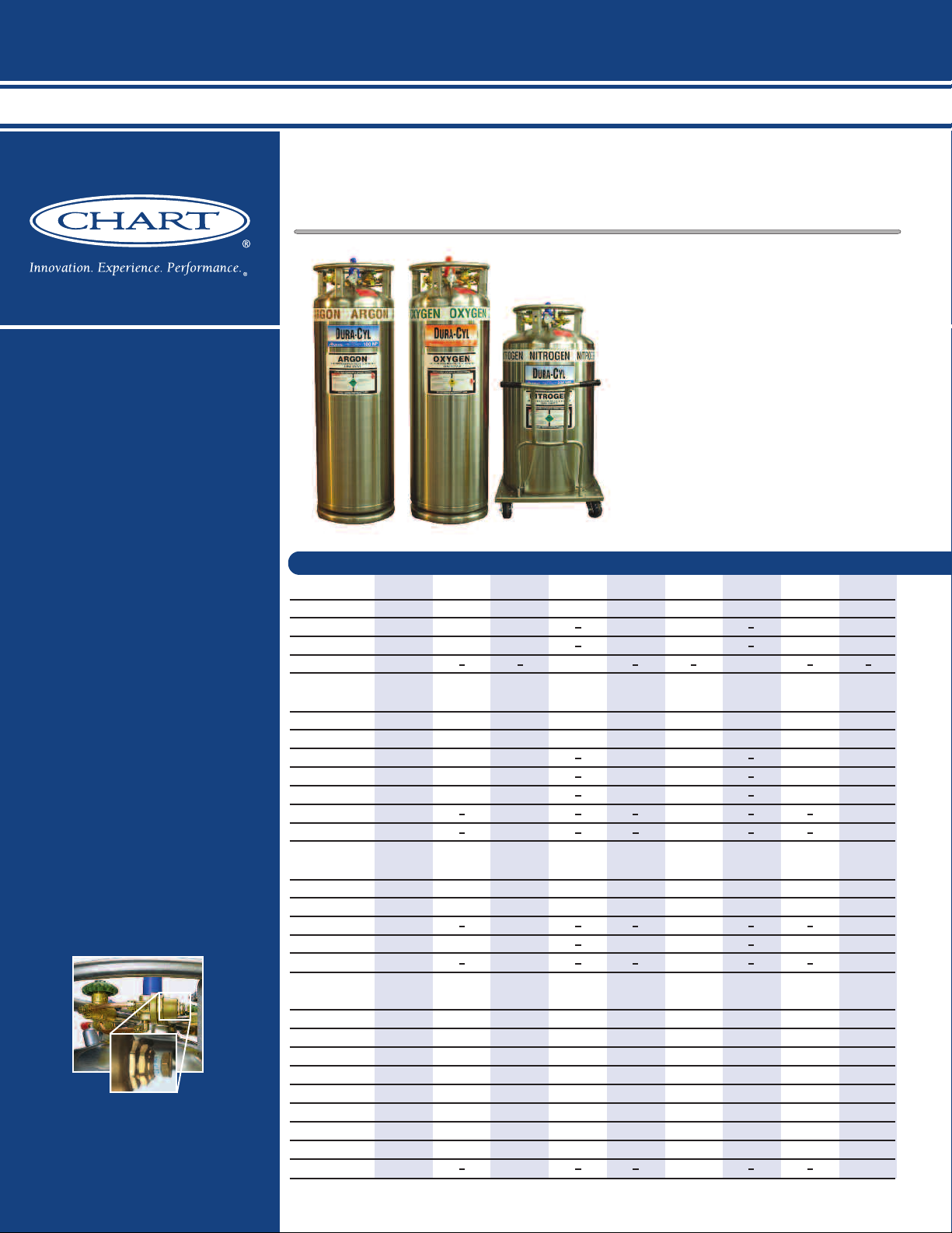
Dura-Cyl
Dura-Cyl Benefits:
• Ideal for liquid nitrogen,
oxygen, argon, CO
or
2
nitrous oxide
• Different sizes, pressures,
and features to meet
your needs
• Stainless steel construction
• Thicker, dent-resistant
outer shell
• Patented durable,
inner-vessel support
system
• Heavy-duty footring and
large diameter handling
ring with four supports
• Combination Pressure
Control Regulator options
• Roto-Cal Liquid Level
Gauge System
• Five-year vacuum
warranty
DURA–CYL
®
PREMIUM LIQUID CYLINDERS
The Dura-Cyl series is a premium transportable
liquid cylinder for cryogenic service. The
patented internal support system design and
quality construction makes the Dura-Cyl series
the most efficient yet rugged cylinder on the
market today. Along with the patented Liquid
Cylinder Control Manifold and our wide choice of
caster base options, the Dura-Cyl Series is also
the most user-friendly cylinder available. Adding
our industry-leading five-year vacuum warranty
and you get the lowest cost of ownership —
making the Dura-Cyl, the preferred choice in
ККККККККК
transportable liquid cylinders.
Footring
MODEL 160 L 160 L 180 L 180 L 180 L 200L 200 L 200 L
Pressure MP HP LP MP HP LP MP HP
LCCM Part Number 10508748 10508756 — 10508764 10496433 — 10508772 10496417
MCR Part Number 10783424 10783467 — 10783491 10783539 — 10783598 10783619
(4)
None
CAPACITY
Liquid (Gross) (liters) 176 176 196 196 196 209 209 209
Liquid (Net) (liters) 165 165 185 185 185 196 196 196
Gas (N2) ft3/ Nm33,685 / 97 3,464 / 91 — 4,099 / 108 3,864 / 102 — 4,375/ 115 4,072/ 108
Gas (O2) ft3/ Nm34,577 / 120 4,348 / 114 — 5,096 / 134 4,843 / 127 — 5,435 / 143 5,048 / 133
Gas (Ar) ft3/ Nm34,448 / 117 4,226 / 111 — 4,961 /130 4,709 / 124 — 5,290 / 139 4,932 /130
Gas (CO2) ft3/ Nm
Gas (N2O) ft3/ Nm
PERFORMANCE
NER (N2) % per day 2.0 2.0 1.5 1.9 1.9 1.85 1.85 1.85
NER (02- Ar) % per day 1.4 1.4 1.0 1.3 1.3 1.2 1.2 1.2
NER (CO2- N2O) % per day — 0.5 — — 0.5 — — 0.5
1
Gas Flow (N2, O2, Ar) SCFH/Nm3/hr 350 / 9.2 350 /9.2 — 350 / 9.2 350 / 9.2 — 400 / 10.5 400 / 10.5
Gas Flow (CO2, N2O) SCFH/Nm3/hr — 110/ 2.9 — — 110 / 2.9 — — 110 / 2.9
Part Number — — 10648450 — — 13277869 — —
(1)(2)
3
— 3,382 / 89 — — 3,766 / 99 — — 4,011 / 105
3
— 3,207 / 84 — --- 3,574 / 94 — — 3,810 / 100
MCR Models have a combination
pressure control regulator with an
exclusive, calibrated micrometer
adjusting screw.
6
DIMENSIONS & PRESSURE RATINGS
Relief Valve Setting psig / barg 230 / 16 350 / 24 22 / 1.5 230 / 16 350 / 24 22 / 1.5 230/ 16 350 / 24
DOT/CTC Rating 4L200 4L292 4L100 4L200 4L292 4L100 4L200 4L292
Diameter in / cm 20 / 50.8 20 / 50.8 20 / 50.8 20 /50.8 20 / 50.8 20 / 50.8 20 / 50.8 20 / 50.8
(3)
Height
Tare Weight lb / kg 250 / 113.4 280 /126.9 210 / 95.2 260 / 117.9 300 / 136.1 210/ 95.2 280 / 126.9 320 / 145.1
Full Weight (N2) lb / kg 517 / 234 531 / 241 540 / 245 557 / 253 580 / 263 559 / 253.5 597 / 271 618 / 280
(1) Net gas capacities at DOT 4L limits. NER = Nominal Evaporation Rate
(2) Most of the Dura-Cyl models are available with permanently installedCGA fittings for medical applications. Contact Customer Service for details.
(3) All dimensions are measured from the floor to the top of the sight gauge protector. (4) Pressure building regulator optional on LP models.
in / cm 59.8 / 151.9 59.8 / 151.9 64.3 /163.3 64.3 / 163.3 64.3 / 163.3 66.6 / 169.2 66.6 / 169.2 66.6/ 169.2
(O2) lb / kg 629 / 285 640 / 290 676 / 307 682 / 309 701 / 318 706 / 320.2 730 / 331 747 /339
(Ar) lb / kg 710/ 322 717 / 325 778 / 354 773 / 351 787 / 357 821 / 372.4 827 / 375 839 / 380
(CO2) lb / kg — 667 / 303 — --- 731 / 331 — — 779 / 353
Page 7

Packaged Gases
Nomenclature
2
3
8
5, 6, 7
4
1
Pressure
Building
Coil
1. Fill / Liquid Valve.
2. Pressure Control Valve.
3. Vent Valve.
4. Pressure Control
Regulator (optional).
5. Pressure Gauge.
6. Pressure Relief Valve.
7. Rupture Disk.
8. Liquid Level Gauge.
Model: LP
Nomenclature
1
3
4
9
6, 7, 8
5
2
Vaporizer
Pressure
Building
Coil
1. Gas Use Valve.
2. Fill / Liquid Valve.
3. Pressure Control Valve.
4. Vent Valve.
5. Combination Pressure
Control Regulator.
6. Pressure Gauge.
7. Pressure Relief Valve.
8. Rupture Disk.
9. Liquid Level Gauge.
Models: MP & HP
The Roto-Cal™ gauge features
an easy-to-read dial liquid
level indicator with swivel
head design.
LCCM Models have an integral
mounted combination pressure
control regulator, isolation valve
and a calibrated dome control knob.
Caster Base
120 L RB 230 L RB 230 L RB 230 L RB 230 L SB 230 L SB 230 L SB 265 L RB 265 L RB 265 L SB 265 L SB
LP LP MP HP LP MP HP MP HP MP HP
— — — 10616546 — 10496468 10496492 — — 10510039 10512561
— — 10783635 10783651 — 10810779 10794027 10783678 10783694 — —
10648396 10648599 — — 10648556 — — — — — —
120 240 240 240 240 240 240 276 276 276 276
110 230 230 230 230 230 230 265 265 265 265
— — 5,024 / 132 4,734 / 124 — 5,024 / 132 4,734 / 124 5,769 / 152 5,438 / 143 5,769 / 152 5,438 / 143
— — 6,244 / 164 5,930 / 156 — 6,244 / 164 5,930 / 156 7,186 / 189 6,811 / 179 7,186 / 189 6,811 / 179
— — 6,073 / 160 5,763 / 151 — 6,073 / 160 5,763 / 151 6,982 / 183 6,634 /174 6,982 / 183 6,634 / 174
— — — 4,614 / 121 — — 4,614 / 121 — 5,305 / 139 — 5,305 / 139
— — — 4,378 / 115 — — 4,378 / 115 — 5,034 / 132 — 5,034 / 132
The Dura-Cyl LP features
a liquid globe valve with
an extended stem for less
ice build-up on the
handle for easier
operation.
2.0 1.5 1.8 1.8 1.5 1.8 1.8 2222
1.4 1.0 1.2 1.2 1.0 1.2 1.2 1.4 1.4 1.4 1.4
— — — 0.5 — — 0.5 — 0.5 — 0.5
— — 400 / 10.5 400 / 10.5 — 400 / 10.5 400 / 10.5 400 / 10.5 400 / 10.5 400 / 10.5 400 / 10.5
— — — 110 / 2.9 — — 110 / 2.9 — 110 / 2.9 — 110 / 2.9
22 / 1.5 22 / 1.5 230 / 16 350 / 24 22 / 1.5 230 /16 350 / 24 230 / 16 350 / 24 230 / 16 350 / 24
4L100 4L100 4L200 4L292 4L100 4L200 4L292 4L200 4L292 4L200 4L292
20 / 50.8 26 / 66.0 26 /66.0 26 / 66.0 26 / 66.0 26 /66.0 26 / 66.0 26 /66.0 26 / 66.0 26 / 66.0 26 / 66.0
51 / 129.5 57.2 / 145.3 57.2 / 145.3 57.2 / 145.3 56.8 / 144.3 56.8 / 144.3 56.8 / 144.3 59.9 / 152.2 59.9 / 152.2 59.5 / 151.1 59.5 / 151.1
165 / 74.8 275 / 125 300 / 136.1 340 / 154.2 311 / 141 300 / 136.1 340 / 154.2 340 /154.2 360 / 163.6 340 / 154.2 360 / 163.6
361 / 164 685 / 311 664 / 301 683 / 310 543 / 247 664 / 301 683 / 310 758 / 344 754 / 343 758 / 344 754 / 343
442 / 201 854 / 388 817 / 370 831 / 377 890 / 407 817 / 370 831 / 377 935 /424 924 / 420 935 / 424 924 / 420
503 / 229 982 / 446 928 / 421 936 / 424 1,018 / 463 928 / 421 936 / 424 1,062 / 481 1,046 / 475 1,062/ 481 1,046 / 475
— — — 868 / 393 — — 868 / 393 — 967 / 439 — 967 / 439
RB = Round Base SB = Square Base
Note: All caster base models are available with stainless steel casters.
Two pull handles are standard
on the round base design.
Some models available
with either round or
square caster bases for
safe and easy mobility.
7
Page 8

Ensuring cryogenic supply capabilities. Any application - Any time
CRYO–CYL
LIQUID CYLINDERS
1
3
8
5, 6, 7
4
2
Vaporizer
Pressure
Building
Coil
Nomenclature
1
1. Gas Use/Vent Valve.
2. Fill / Liquid Valve.
3. Pressure Control Valve.
4. Pressure Control
Regulator.
5. Pressure Gauge.
6. Pressure Relief Valve.
7. Rupture Disk.
8. Liquid Level Gauge.
Cryo-Cyl
The Cryo-Cyl 180L HP is built with
our patented internal support system design and quality construction
but at an economical value over our
premium Dura-Cyl Series. While still
Cryo-Cyl Benefits:
• Ideal for liquid nitrogen,
oxygen, argon, CO
or
2
nitrous oxide
maintaining our standard warranty,
the Cryo-Cyl 180L HP meets the
rugged market demands for a basic
liquid cylinder.
• Stainless steel construction
• Thicker, dent-resistant
outer shell
MODEL 80 L 180 L
• Patented durable,
inner-vessel support
system
CAPACITY
• Heavy-duty footring and
large diameter handling
ring with two supports
• Roto-Cal Liquid Level
Gauge System
• Five-year vacuum
PERFORMANCE
warranty
DIMENSIONS & PRESSURE RATINGS
Standard on all of our liquid cylinders are color-coded model labels,
protectors and two safety devices.
Protector Color Pressure
Yellow LP
Blue MP
Orange HP
Red VHP
8
(1)(2)
Liquid (Gross) (liters) 85 196
Liquid (Net) (liters) 80 185
Gas (N2) ft3/ Nm31,680 / 44 3,864 / 102
Gas (O2) ft3/ Nm32,108 / 55 4,843 / 127
Gas (Ar) ft3/ Nm32,049 / 54 4,709 / 124
Gas (CO2) ft3/ Nm31,640 / 43 3,766 / 99
Gas (N2O) ft3/ Nm31,555 / 41 3,574 / 94
NER (N2) % per day 3.0 1.9
NER (02- Ar) % per day 2.0 1.3
NER (CO2- N2O) % per day 0.8 0.5
Gas Flow (N2, O2, Ar)
Gas Flow (CO2, N2O) SCFH/Nm
Relief Valve Setting psig / barg 350 / 24 350 / 24
Operating Pressure
DOT/CTC Rating 4L292 4L292
Diameter in / cm 20 / 50.8 20 / 50.8
(5)
Height
Tare Weight lb / kg 165/ 74.8 300 / 136.1
Full Weight (N2) lb / kg 287 / 130 580 / 263
(O2) lb / kg 340 / 155 701 / 318
(Ar) lb / kg 377 / 171 787 / 357
(CO2) lb / kg 353 / 161 731 / 331
(1) Net gas capacities at DOT 4L limits.
(2) The Cryo-Cyl modelis available with permanently installed CGA fittings for medical applications.
Contact Customer Service fordetails.
(3) Gas flows of twice the continuous flow rate can be achieved for one hr. over aneighthr. period.
(4) Pressure building regulator range (50-175 psi).
(5) Height dimensions are measured from the floor to the top of the sight gauge protector.
Specifications
Pressure HP HP
Part Number 10648610 14248701
(3)
SCFH/Nm3/hr 100 / 2.6 200 / 5.3
3
/hr 35 / 0.9 65 / 1.7
(4)
psig / barg 125 / 8.6 125 / 8.6
in / cm 39.5 / 100.3 64.3 /163.3
Page 9

Laser-Cyl Benefits:
LASER–CYL
HIGH PRESSURE LIQUID CYLINDERS
1
3
4
9
6, 7, 8
5b
5a
2
Vaporizer
Pressure
Building
Coil
Nomenclature
1
1. Gas Use Valve.
2. Fill / Liquid Valve.
3. Pressure Control Valve.
4. Vent Valve.
5a.Pressure Control
Regulator.
5b.Economizer Regulator
6. Pressure Gauge.
7. Pressure Relief Valve.
8. Rupture Disk.
9. Liquid Level Gauge.
Model: 200
• Built-in vaporizer coils
supply constant pressure
gas at continuous flow
rates up to 575 SCFH
(15.1 Nm
3
/hr)
Packaged Gases
Laser-Cyl
Laser-Cyl is designed specifically
for laser applications, as a high
performance option to expensive
high pressure cylinder tanks. The
Laser-Cyl delivers optimal pressure
up to 500 psig (34.5 bar) and
continuous flow rates up to 575
3
SCFH (15.1 Nm
/hr).
• Piping controls located
on top for easy operation
MODEL 200 450
Specifications
and maintenance
Part Number 10619771 10619659
• Differential pressure
liquid level gauge
accurately displays
product level (450 only)
• Insulation system
provides low NER for
longer holding time
• Available in 200 and 450
liter sizes with an
optional pallet frame
CAPACITY
Liquid (Gross) (liters) 200 450
Liquid (Net) (liters) 196 428
Gas (N2) ft3/ Nm33,521 / 93 7,922 / 208
Gas (O2) ft3/ Nm34,674 / 123 10,519 / 276
Gas (Ar) ft3/ Nm34,552 / 120 10,241/269
Gas (CO2) ft3/ Nm33,537 / 93 7,960/ 209
Gas (N2O) ft3/ Nm33,333 / 88 7,516 / 197
PERFORMANCE
NER (N) % per day 2.0 2.0
NER (02- Ar) % per day 1.4 1.4
NER (CO2- N2O) % per day 0.5 0.5
Gas Flow (N2, O2, Ar) SCFH/Nm
Gas Flow (CO2, N2O) SCFH/Nm
DIMENSIONS & PRESSURE RATINGS
Relief Valve Setting psig / barg 500 /34.5 500 /34.5
DOT/CTC Rating 4L412 4L412
Diameter (cylinder) in / cm 20 / 50.8 30 / 76.2
Height (cylinder)
Base Width (frame) in / cm — 34 / 86.4
Base Depth (frame) in / cm — 34 / 86.4
Base Height (frame) in / cm — 73.8 /187.5
Tare Weight
Full Weight (N2) lb / kg 630 / 286 1,839 / 836
(1)
(2)
(3)
(O2) lb / kg 762 / 346 2,136 / 971
(Ar) lb / kg 846 / 384 2,324 / 1,056
(CO2) lb / kg 791 / 360 2,202 / 1,001
(1) Net gas capacities at DOT 4L limits.
(2) All dimensions are measured from the floor to the top of the sight gauge protector.
(3) Weights are approximate and vary with pallet design.
Pressure VHP VHP
3
/hr 350 / 9.2 575 / 15.1
3
/hr 110 / 2.9 180 / 4.7
in / cm 65.8 / 167.1 61.3/ 155.7
lb / kg 375 / 170 1,265 / 574
9
Page 10

Ensuring cryogenic supply capabilities. Any application - Any time
MEGA–CYL
PALLETIZED CYLINDERS
Nomenclature
1
3
4
9
6, 7, 8
5b
5a
2
Vaporizer
Pressure
Building
Coil
1. Gas Use Valve.
2. Fill / Liquid Valve.
3. Pressure Control Valve.
4. Vent Valve.
5a.Pressure Control
Regulator.
5b.Economizer Regulator
6. Pressure Gauge.
7. Pressure Relief Valve.
8. Rupture Disk.
9. Liquid Level Gauge.
Mega-Cyl
Mega-Cyl Benefits:
• Tough, durable stainless
steel construction
• High-performance Super
Insulation
• Easily accessible valves
and gauges
• Spray header for pump
filling on vent tube
• Accurate differential
pressure contents gauge
(non-electric)
The Mega-Cyl series is Chart’s line of palletized cylinders designed for
easy transport with capacities from 450 to 1000 liters. Engineered with
the volume user in mind, it’s ideal for construction sites, remote purging operations and back-up systems. Mega-Cyl cylinders are available in
all services up to 500 psig (34.5 barg) and are specifically designed to
optimize distribution costs.
Examine the rugged, maneuverable Mega-Cyl series and you’ll find all
the quality features you expect from the industry leader, Chart.
Mechanical differential
pressure gauge standard
for contents indication.
10
Page 11

Packaged Gases
Specifications
MODEL 450 600 800 1000
Pressure HP HP HP HP
Part Number 10588979 11652389 10671262 10752281
CAPACITY
Liquid (Gross) (liters) 450 660 880 1056
Liquid (Net)
Gas (N2) ft3/ Nm
Gas (O2) ft3/ Nm
Gas (Ar) ft3/ Nm
Gas (CO2) ft3/ Nm
(1)
(liters) 428 600 800 950
3
3
3
3
8,875 / 233.2 14,755/ 387.8 19,672 / 517 23,363 / 614
11,111 / 292 18,240 / 479.3 24,320 / 639.1 28,843 / 758
10,812 / 284.1 17,823 / 468.4 23,767 / 624.6 28,234 / 742
8,652 / 227.4 12,191 / 320.4 16,255 / 427.2 18,580 / 488.3
PERFORMANCE
NER (N2) % per day 2.1 1.8 1.8 1.3
NER (02, Ar) % per day 1.4 1.2 1.2 0.9
NER (C02,N20) % per day 0.6 0.5 0.5 0.3
Gas Flow (N2, O2, Ar) SCFH/Nm
Gas Flow (CO2) SCFH/Nm
3
/hr 575 / 15.1 750 / 19.7 880 / 23.1 960 / 25.2
3
/hr 195 / 5.1 250 / 6.6 280 / 7.4 300 / 7.9
DIMENSIONS & PRESSURE RATINGS
Relief Valve Setting psig / barg 350 / 24 350 / 24 350 / 24 350 / 24
DOT/CTC/ASME Rating 4L292 ASME Sec 8/Div1 ASME Sec 8/Div1 ASME Sec 8/Div1
Diameter (cylinder) in / cm 30 / 76.2 42 / 106.7 42 / 106.7 42 / 106.7
Height(cylinder) in / cm 62 / 158 63 / 159 67 / 171 76 / 191
Base Width (frame)
Base Depth (frame)
Height (frame)
Tare Wt. (cyl +frame)
(2)
in / cm 34 / 86.4 45 /114 45 / 114 45 / 114
(2)
(2)
in / cm 34 / 86.4 45 /114 45 / 114 45 / 114
in / cm 74 / 188 72 /183 80 / 203 80 / 203
(3)
lb / kg 1,275 / 580 1,700 / 773 2,500/ 1,136 2,650 / 1,205
Full Weight (N2) lb / kg 1,918 / 872 2,769 / 1,254 3,926 / 1,784 4,343 / 1,974
(O2) lb / kg 2,195 / 998 3,210 / 1,459 4,514 / 2,052 5,038 / 2,290
(Ar) lb / kg 2,393 / 1,088 3,543 /1,610 4,958 / 2,253 5,569 / 2,532
(CO2) lb / kg 2,265 / 1,029 3,324 / 1,510 4,666/ 2,120 5,218 / 2,372
(1) CO2values and 450 liter models based on DOT4L fill density. N2, O2and Ar values based on net volume at 0 psig.
(2) Customized pallets are available upon request.
(3) Weights are approximate and vary with pallet design.
11
Page 12

Ensuring cryogenic supply capabilities. Any application - Any time
WARNING!
DO NOT REMOVE ANY FITTINGS UNLESS
CYLINDER IS BEING SERVICED BY
AUTHORIZED PERSONNEL. DO NOT USE
CYLINDER IF WIRE SEAL IS MISSING,
DAMAGED OR HAS BEEN TAMPERED WITH
OR IF THERE IS ANY DOUBT AS TO THE
CONTENTS CONTAINED IN THIS CYLINDER.
FAILURE TO FOLLOW ANY OF THESE
INSTRUCTIONS MAY RESULT IN DEATH,
SEVERE PERSONAL INJURY AND/OR
PROPERTY DAMAGE.
CGA Fitting Restraints
Maintaining control of product service is of the utmost importance when using liquid cylinders. Chart offers
CGA Fitting Restraints that provide a clear visual indication before any attempt is made to remove or change
use-fittings. Installing and inspecting these restraints ensures that cylinders are filled with the correct
product each and every time. Designs comply with CGA bulletin #SB-26.
A B
Type A & B are standard on all DOT cylinders.
SDC
SDC (Single Direction Clutch,
GENERANT). Also available with
internal check valve.
12
Brazed
Warning Label
(4 1/2” x 3 1/2”)
P/N 10998521
Page 13

Packaged Gases
Liquid Cylinder Accessories
M45 Manifold
The M45 manifold is a convenient,
automatic way of increasing
the gas delivery rate to any
application. The unique changeover valve allows easy manual
selection of the primary bank of
cylinders. An indicator light shows
when the system switches to the
reserve bank so replacement
cylinders can be ordered.
Handling Cart
A variety of handling carts and
accessories are available to
make the transportation of
liquid cylinders safe and easy.
They optimize fast and safe
deliveries by decreasing back
injuries, along with lowering
Worker’s Compensation costs.
Carriage Cart
The four-wheeled carriage cart
permanently attaches to the
lower section of any 20 inch (508
mm) diameter liquid cylinder.
The front pull handle is attached
to the dual swivel wheels for
easy mobility. Rear wheels are
stationary so the carriage cart
with liquid cylinder can be
backed into a tight location.
Ideal for lab users with dedicated
liquid cylinders.
Dual Relief Valves
With dual relief valves one
cylinder can be used for both
liquid (low pressure) or gas
(medium pressure) accounts,
which maximizes the flexibility
of your liquid cylinders.
Hose
Stainless-steel transfer hoses
that remain flexible during liquid
transfer can be coupled with a
bronze phase separator. Ideal
for safe discharge of LN2into
open dewars.
Vent Muffler
The vent muffler can be attached
to the vent connection of the
liquid cylinder to reduce the
venting noise during the fill.
Plastic for inert service and
brass for oxygen service.
13
Page 14

Ensuring cryogenic supply capabilities. Any application - Any time
40
35
30
25
20
15
10
5
0
Depressurization (flash) Losses
Loss (%)
Bulk Tank Pressure (psig)
0 40 80 120 160 200 240
Argon
Oxygen
Nitrogen
Lo-Loss
Lo-Loss Benefits:
• Designed for pressure
transfer filling in argon,
oxygen and nitrogen*
service
• Automatic liquid cylinder
pressure regulation
throughout the fill cycle
• Modular design allows
integration into existing
systems
• Automatic shutoff
improves labor utilization
by allowing unattended
filling
• Promotes DOT-compliant
filling and eliminates
wasted product associated
with vent filling
Lo-Loss is an automated filling
system that dramatically reduces
depressurization (flash) losses
during liquid cylinder filling. By
maintaining an optimal pressure
difference between the bulk tank
and liquid cylinder, losses are
kept at a minimum without
increasing fill times.
* Each product requires a
separate pressure control unit
The Lo-Loss System reduces flash losses during liquid cylinder filling to 3-5% without compromising fill times.
For example, flash losses of up to 23%* (1,217 SCF) will occur when filling a 200 liter liquid cylinder in argon
service from a bulk tank at 150 psig (see graph). By maintaining the liquid cylinder vent pressure at 30 psig
lower than the bulk tank pressure, Lo-Loss reduces flash losses in this example to 3%* (160 SCF).
* An additional 2-4% of product based on gross volume will be lost due to transfer and cool-down losses.
14
Page 15

Argon Maximizer Benefits:
Cylinder Pressure (PSIG)
Hold Time (Hours)
12 Hour Hold Time
52 Hour Hold Time
230
100
50
0 12 32
52
DOT Full Liquid Cylinder Pressure Rise
Comparison to Relief Valve with Argon
Filled with
Argon CryoFill
Filled
without
Argon
CryoFill
• Reduce liquid cylinder fill
losses by as much as 73%*
• Increase customer
satisfaction with longer
hold times (40 hours on
average)
• Reduce liquid cylinder
fill time labor
• Eliminate just-in-time
liquid cylinder filling
*Contact Chart for a customized
economic analysis for details.
Packaged Gases
Argon Maximizer
The Argon Maximizer is an efficient cryogenic heat
exchanger designed to reduce filling losses in argon
liquid cylinders. It operates with a simple heat
transfer principle that consumes inexpensive liquid
nitrogen to subcool the argon during the liquid
cylinder filling process. The results are lower liquid
cylinder filling losses and colder liquid for longer
holding times — giving you better handling logistics
at your fill plant and at your customer’s site. The
Argon Maximizer can also be used with Lo-Loss to
further optimize the filling process.
Note: Argon bulk tank saturated at 130 psig, and cylinders filled
with the Lo-Loss system.
15
Page 16

Ensuring cryogenic supply capabilities. Any application - Any time
Ultra-Helium Dewars
The Ultra Helium Dewar’s
controls are conveniently
located on the top, with
nesting fill couplings to
accept various standard
transfer line sizes. The
optional electric pressure
builder can quickly
increase pressure for
liquid transfer while
maintaining low heat leak.
It has two pre-set ranges
(4 or 8 psig/0.3 or 0.6
barg) for efficient liquid
helium withdrawal.
Ultra-Helium Dewars
Benefits:
• Maximum durability and
lightweight
• Outstanding thermal
performance
• Large ball valves for up
to 3/4” (19 mm)
transfer lines
Model 250 L Model 100 L Model 60 L
The Ultra Helium Dewars are designed and built for reliable transport.
They are light, maneuverable and durable, while providing superior
thermal performance. The unique neck tube design provides proven
support during transportation. The outboard caster base provides
maximum stability in a compact design.
Available in sizes ranging from 60 to 500 liters. The Ultra Helium
Dewars are suitable for air transport (IATA conforming) with the
optional absolute pressure relief valve. All models are 100% nonmagnetic for Magnetic Resonance Imagery (MRI) service.
16
Page 17

ULTRA–HELIUM DEWARS
BUILT FOR RELIABLE TRANSPORT
Packaged Gases
*
Nomenclature
1.
Quick Coupling Stack
2.
Liquid Valve
3.
Handle Assembly
4.
Swivel Caster Non-Magnetic
5.
Rigid Caster Non-Magnetic
6.
Vent Valve Connection
7.
V-Band Clamp
8.
Aux. Relief Isolation Valve
9.
Aux. Relief Valve
1.0 psig (.07 barg)
10.
Pressure Gauge
11.
Secondary Relief Valve
12 psig (.8 barg)
12.
Main Relief Valve
13.
Main Vent Valve
10 psig (.7 barg)
Specifications
MODEL 60 100 250 500
Part Number 10533409 10533417 9923629 11202581
CAPACITY
Liquid (Gross) (liters) 66 110 275 550
Liquid (Net) (liters) 60 100 250 500
PERFORMANCE
NER (N2)
MAWP psig / barg 10.0 / 0.7 10.0 / 0.7 10.0 / 0.7 10.0 / 0.7
DIMENSIONS & PRESSURE RATINGS
Relief Valve Setting psig / barg 10.0 / 0.7 10.0 / 0.7 10.0 / 0.7 10.0 / 0.7
Secondary Relief Valve psig / barg 12.0 / 0.8 12.0 / 0.8 12.0 / 0.8 12.0 / 0.8
Diameter in / cm 24.0 / 61.0 24.0 / 61.0 32.0 / 81.3 42.0 / 106.7
Height in / cm 50.1 / 127.3 59.0 / 147.9 67.4 / 171.1 70.6 / 179.3
Dip Tube Length
Tare Weight lb / kg 184 / 83 212 / 96 348 / 158 480 / 218
(1)
(2)
(1) The dip tube length is measured from the tank flange to the bottom of the inner vessel.
(2) Based on gross capacity.
Contact Customer Service forafull line of Helium Accessories.
% per day 1.75 1.25 1.0 1.0
(1)
in / cm 35.0 / 88.9 43.8 /111.1 54.4 / 138.2 56.4 / 143.1
17
Page 18

Ensuring cryogenic supply capabilities. Any application - Any time
Cylinder Repair & Chart Parts
Quality service and 100%
satisfaction is what you’ll
get when you have your
beverage and liquid
cylinders repaired by
Chart, the same team
that builds them.
• Personalized account
information
Benefits
® Complete cosmetic, revac and
rebuild services
® No hassle shipping with pick-up
and delivery at your door
® Free freight available
® Cylinder inspection with estimate
prior to work
® Component replacement with
stock OEM parts
® DOT/TC and ASME coded facility
® Three/Five year vacuum warranty
® Lowest life-cycle cost
® Service on all makes and models
® Guaranteed 100% satisfaction
® Quickest turn-around time in
the industry
Account Information
Access shipment tracking,
transaction history and
personalized account
information for convenient
account management.
• Order history and
shipment tracking
• Shopping cart stores
your parts before you buy
• Parts available for all
makes and models
• Same-day shipment on
all stock parts
For All Your Parts Needs…
www.chartparts.com
18
Easy To Locate Parts
Looking for a part? Search
our entire inventory of parts
and accessories in seconds.
Locate your part by reviewing
tank diagrams or search by
keyword or part number.
Personalized Service
Have a question about your order?
We’re ready to help! If you can’t
find what you’re looking for, give
us a call at 1-800-400-4683.
Page 19

Packaged Gases
SCF of GAS / Liter of LIQUID
Pressure Argon Nitrogen Oxygen CO
psig psig
0 29.69 24.60 30.36 225 23.58 18.35 24.24 20.34
25 28.24 23.17 28.89 250 23.17 17.89 23.83 20.07
50 27.32 22.26 27.97 275 22.77 17.43 23.43 19.82
75 26.60 21.53 27.25 22.40 300 22.37 16.96 23.03 19.58
100 25.98 20.89 26.63 21.96 325 21.98 16.47 22.64 19.34
125 25.43 20.33 26.09 21.57 350 21.43 15.96 22.25 19.11
150 24.93 19.80 25.59 21.23 375 21.19 15.42 21.86 18.88
175 24.46 19.30 25.12 20.91 400 20.79 14.80 21.47 18.66
200 24.01 18.82 24.67 20.61 425 20.39 14.07 21.08 18.44
Weight Gas Liquid
Pounds Kilograms Cubic Feet Cubic Meters Gallons Liters
(Lb) (Kg) (SCF) (Nm3) (Gal) (L)
1 Pound 1.0 0.4536 9.671 0.2543 0.08600 0.3255
1 Kilogram 2.205 1.0 21.32 0.5605 0.18957 0.7176
1 SCF Gas 0.1034 0.04690 1.0 0.02628 0.008893 0.03366
1 Nm3Gas 3.933 1.7840 38.04 1.0 0.3382 1.2802
1 Gal Liquid 11.630 5.276 112.5 2.957 1.0 3.785
1 L Liquid 3.072 1.3936 29.71 0.7812 0.2642 1.0
1 Pound 1.0 0.4536 13.803 0.3627 0.1481 0.5606
1 Kilogram 2.205 1.0 30.42 0.7996 0.3262 1.2349
1 SCF Gas 0.07245 0.03286 1.0 0.02628 0.01074 0.04065
1 Nm3Gas 2.757 1.2506 38.04 1.0 0.4080 1.5443
1 Gal Liquid 6.745 3.060 93.11 2.447 1.0 3.785
1 L Liquid 1.782 0.8083 24.60 0.6464 0.2642 1.0
Weight Gas Liquid
Pounds Kilograms Cubic Feet Cubic Meters Gallons Liters
(Lb) (Kg) (SCF) (Nm3) (Gal) (L)
1 Pound 1.0 0.4536 12.076 0.3174 0.1050 0.3977
1 Kilogram 2.205 1.0 26.62 0.6998 0.2316 0.8767
1 SCF Gas 0.08281 0.03756 1.0 0.02628 0.008691 0.0329
1 Nm3Gas 3.151 1.4291 38.04 1.0 0.3310 1.2528
1 Gal Liquid 9.527 4.322 115.1 3.025 1.0 3.785
1 L Liquid 2.517 1.1417 30.38 0.7983 0.2642 1.0
SCF (Standard Cubic Foot) gas measured at 1 atmosphere and 70°F. Nm3(normal cubic meter) measured at 1 atmosphere and 0°C.
Liquid measured at 1 atmosphere and boiling temperature. All values rounded to nearest 4/5 significant numbers.
2
Pressure Argon Nitrogen Oxygen CO
Argon
Nitrogen
Oxygen
Gas Densities at Liquid Pressures
2
Conversion Data
Carbon Dioxide
Weight Gas Liquid Solid
Pounds Tons Kilograms Cubic Feet Cubic Meters Gallons Liters Cubic Feet
(Lb) (T) (Kg) (SCF) (Nm3) (Gal) (L) (Cu Ft)
1 Pound 1.0 0.0005 0.4536 8.741 0.2294 0.11806 0.4469 0.010246
1 Ton 2000.0 1.0 907.2 17,483.0 458.8 236.1 893.9 20.49
1 Kilogram 2.205 0.0011023 1.0 19.253 0.5058 0.2603 0.9860 0.2260
1 SCF Gas 0.1144 — 0.05189 1.0 0.02628 0.013506 0.05113 0.0011723
1 Nm3Gas 4.359 0.002180 1.9772 38.04 1.0 0.5146 1.9480 0.04468
1 Gal Liquid 8.470 0.004235 3.842 74.04 1.9431 1.0 3.785 0.08678
1 L Liquid 2.238 0.0011185 1.0151 19.562 0.5134 0.2642 1.0 0.02293
1 Cu Ft Solid 97.56 0.04880 44.25 852.8 22.38 11.518 43.60 1.0
SCF (Standard Cubic Foot) gas measured at 1 atmosphere and 70°F. Nm3(normal cubic meter) gas measured at 1 atmosphere and 0°C.
Liquid measured at 21.42 atmospheres and 1.7°F. All values rounded to nearest 4/5 significant numbers.
Solid measured at -109.25°F.
19
Page 20

Phone
1-800-400-4683
Fax
1-952-758-8275
Worldwide
1-952-758-4484
Chart Inc.
407 Seventh Street NW
New Prague, MN 56071
www.chart-ind.com
©2009 Chart Inc.
P/N 13962022
 Loading...