

Page 1

®
MXD SERIES 200
WASTE OIL HEATER
Installation and Operating
Instructions
Lanair Products LLC
4109 Capital Circle
Janesville,Wisconsin 53546
1-888-370-6531
www.lanair.com
Page 2

®
BEFORE YOU BEGIN INSTALLATION...
IMPORTANT
Read and understand this manual completely before beginning installation.
s This heater is for commercial and industrial use only. This unit is not intended for residential
use.
s This heater must be installed and/or inspected by a licensed heating contractor before
operation. Installer should be trained and thoroughly familiar with the installation and
operation of oil-fired heaters.
s Installation of this unit must be made in accordance with state and local codes or authori-
ties having jurisdiction over environmental control, fuel, fire and electrical safety.
s N.F.P.A. (National Fire Protection Association Publications for Heater Installation)
NFPA No. 30 Flammable and Combustible Liquids Code
NFPA No. 31 Standard for the Installation of Oil Burning Equipment
NFPA No. 70 National Electric Code
NFPA No. 80 A&B Repair Garages and Parking Structures
NFPA No. 211 Standard for Chimneys, Fireplaces,Vents, and
Solid Fuel Burning Appliances
The above standards are available
Park, Quincey,MA 02269
from the National Fire Protection Assn., Battery March
s Read and familiarize yourself with these instructions and associated photos, diagrams and
illustrations before beginning installation or operation.These instructions should be followed closely, to achieve the best possible results.
If you have questions or concerns at any time during the installation, stop the installation
and contact a Lanair Service Representative.
s Check to make sure you have all the required components needed for proper installation
and operation.
s Check each component for visible damage. If you find a damaged component, contact a
Lanair Service Representative for a replacement. D
s This heater is designed to provide economically and environmentally friendly disposal of
waste oil. Due to the nature of the fuel used, this heater should not be relied upon as the
sole source of heat.
s Read and understand the warranty. Fill out the enclosed warranty card and return within
10 days of purchase.
o not install broken or damaged parts.
QUESTIONS?... Contact Customer Service at 1-888-370-6531 M-F 8:00 am- 4:15 pm CST
2
Page 3

MXD SERIES 200 WASTE OIL HEATER
Installation and Operating Instructions
Table of Contents:
Rules For Safe Installation and Operation . . . . . . . . . . . . . . . . . . . . . . . . . . . . . . . . . . . page 2
Sec. 1 General Specifications and Hazards . . . . . . . . . . . . . . . . . . . . . . . . . . . . . . . . . . . . . . . . . . page 4
Sec. 2 Heater Installation . . . . . . . . . . . . . . . . . . . . . . . . . . . . . . . . . . . . . . . . . . . . . . . . . . . . . . . . . . . . . . page 10
Sec. 3 Chimney /Vent System . . . . . . . . . . . . . . . . . . . . . . . . . . . . . . . . . . . . . . . . . . . . . . . . . . . . . . . . page 12
Sec. 4 Draft . . . . . . . . . . . . . . . . . . . . . . . . . . . . . . . . . . . . . . . . . . . . . . . . . . . . . . . . . . . . . . . . . . . . . . . . . . . . . page 15
Sec. 5 Fuel Supply Tank /Piping Installation . . . . . . . . . . . . . . . . . . . . . . . . . . . . . . . . . . . . . . . . . page 15
Sec. 6 Fuel Supply Pump/Piping . . . . . . . . . . . . . . . . . . . . . . . . . . . . . . . . . . . . . . . . . . . . . . . . . . . . . page 17
Sec. 7 Compressed Air Installation . . . . . . . . . . . . . . . . . . . . . . . . . . . . . . . . . . . . . . . . . . . . . . . . . . . page 19
Sec. 8 Electrical Connections/Wiring Diagram . . . . . . . . . . . . . . . . . . . . . . . . . . . . . . . . . . . . . . page 20
Sec. 9 Controls . . . . . . . . . . . . . . . . . . . . . . . . . . . . . . . . . . . . . . . . . . . . . . . . . . . . . . . . . . . . . . . . . . . . . . . . . page 23
Sec.10 Priming Fuel Pump . . . . . . . . . . . . . . . . . . . . . . . . . . . . . . . . . . . . . . . . . . . . . . . . . . . . . . . . . . . . page 25
Sec.11 Burner Start-Up Procedure . . . . . . . . . . . . . . . . . . . . . . . . . . . . . . . . . . . . . . . . . . . . . . . . . . . . page 27
Sec.12 Flame Adjustment . . . . . . . . . . . . . . . . . . . . . . . . . . . . . . . . . . . . . . . . . . . . . . . . . . . . . . . . . . . . . page 29
Sec.13 Maintenance Schedule / Service Adjustments . . . . . . . . . . . . . . . . . . . . . . . . . . . . . . page 32
Sec.14 Troubleshooting . . . . . . . . . . . . . . . . . . . . . . . . . . . . . . . . . . . . . . . . . . . . . . . . . . . . . . . . . . . . . . . page 44
Sec.15 Warranty Certificate . . . . . . . . . . . . . . . . . . . . . . . . . . . . . . . . . . . . . . . . . . . . . . . . . . . . . . . . . . . . page 49
Sec.16 Burner Reference Diagram . . . . . . . . . . . . . . . . . . . . . . . . . . . . . . . . . . . . . . . . . . . . . . . . . . . .page 51
Visit our website at: www.lanair.com
3
Page 4
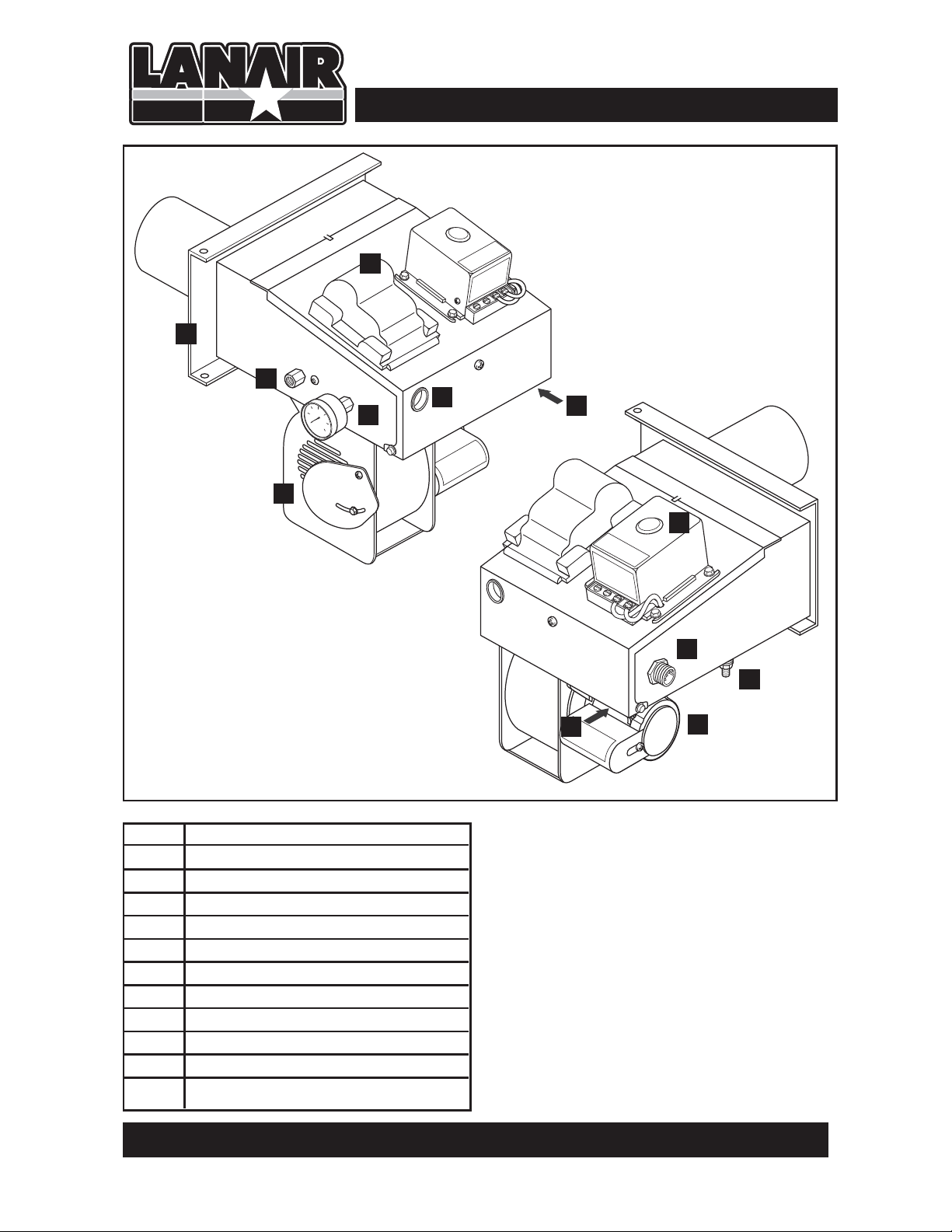
Section 1 - General Specifications & Hazards
2
1
3
6
4
5
8
7
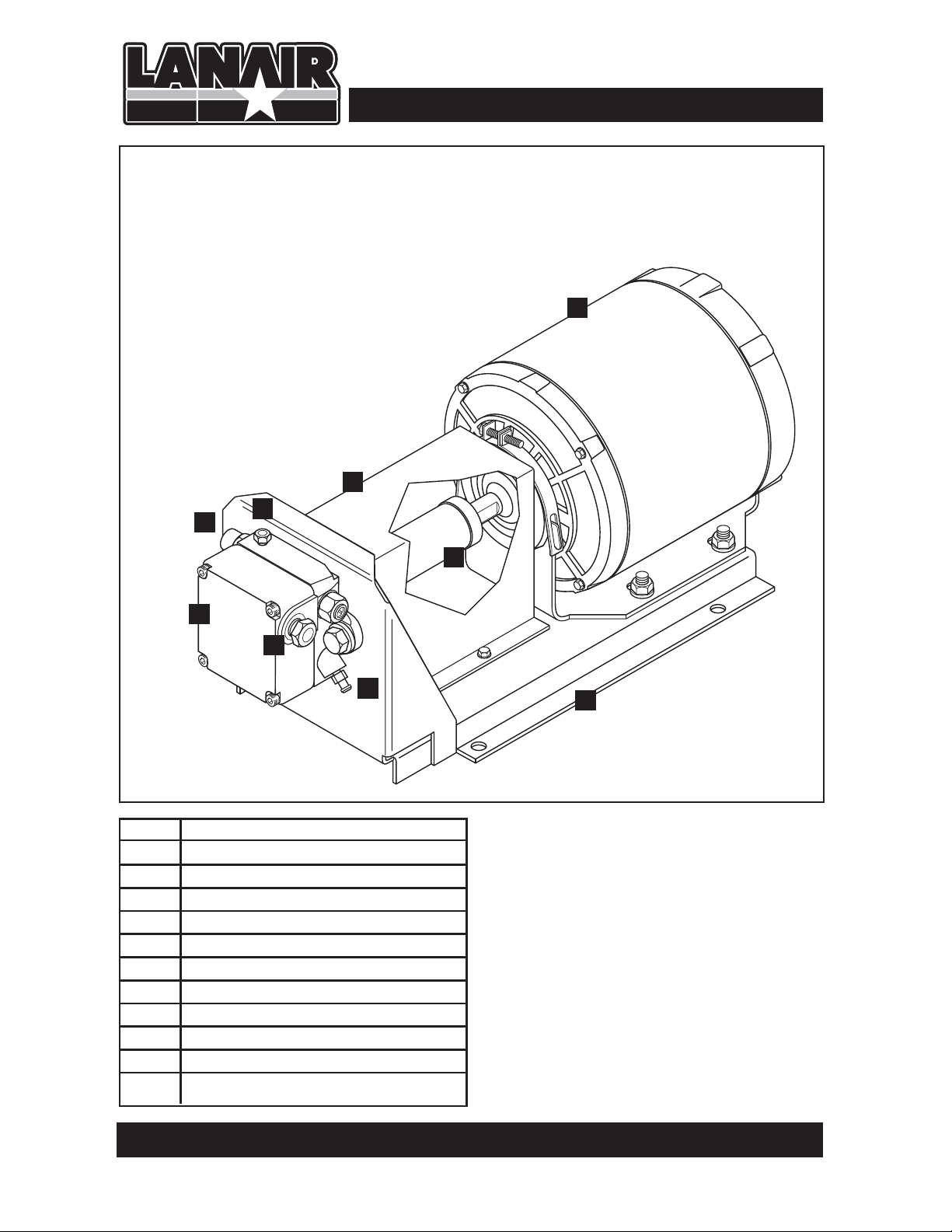
MXD 200 Series Burner
NOTE: This burner is intended for use
with Lanair waste oil fired heaters only
No. Description
1 Mounting Plate
2 Ignitor Transformer
3 Fuel Line Inlet
4 Fuel Pressure Gauge
5 Combustion Air Baffle
6 View Port
7 Oil Primary Safety Control
8 Waste Oil/Fuel Oil Switch
9 Quick Disconnect Receptacle
10 Air Supply Inlet
11 Combustion Blower Motor
9
10
8
11
Burner AssemblyPerformance Ratings
Voltage . . . . . . . . . . . . . . . . . . . . . . 115 vac
Cycles . . . . . . . . . . . . . . . . . . . . . . . . . . 60 hz
Total Operating Amperage . . . . . . . . 4.9
Weight . . . . . . . . . . . . . . . . . . . . . . . . .31 lbs
Oil Primary . . . . . . . . . . . . . . . . . . 0.2 amps
Pre-Heater Block . . . . . . . . . . . . .2.6 amps
Ignitor Transformer . . . . . . . . . . 0.3 amps
QUESTIONS?... Contact Customer Service at 1-888-370-6531 M-F 8:00 am- 4:15 pm CST
4
Page 5
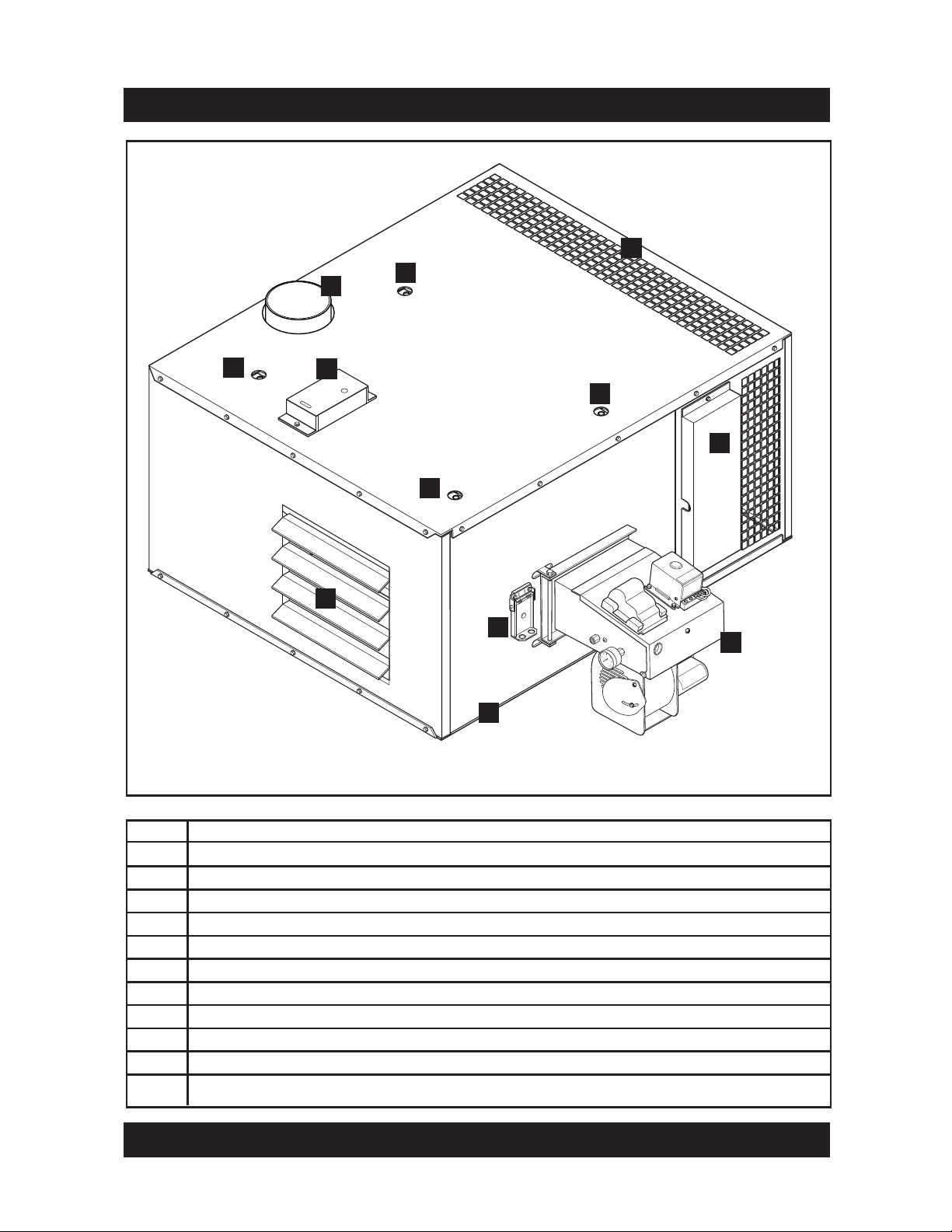
Section 1 - General Specifications & Hazards
9
4
2
2
3
2
7
2
1
5
6
8
No. Description
1 Adjustable Air Flow Louvers
2 Mounting Holes
3 Fan Limit Switch
4 Option Top Exhaust
5 Flame View Port
6 Burner Assembly
7 Electrical Connections Cover
8 Secondary Air Filter/Regulator Location
9
Blower Assembly
Visit our website at: www.lanair.com
5
Page 6
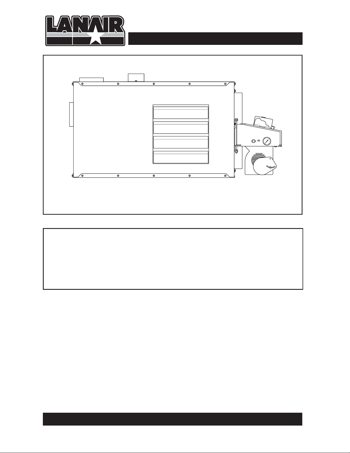
MXD-200 FRONT
Section 1 - General Specifications & Hazards
DIMENSIONS:
MXD-200 Height: 24” Width: 40.25” Depth: 54” Weight: 460 LBS
FIRING CAPACITIES:
MXD-200 Nozzle @ 1.43 gallons/hour, No. 2 fuel oil/used crankcase oil
QUESTIONS?... Contact Customer Service at 1-888-370-6531 M-F 8:00 am- 4:15 pm CST
6
Page 7
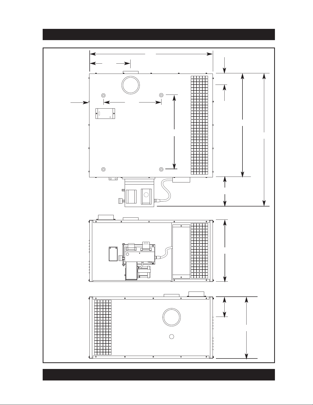
16.5”
Section 1 - General Specifications & Hazards
54”
TOP VIEW
- MXD 200
RIGHT SIDE
- MXD 200
5.5”
22.5”
6” diameter pipe
28.75”
4.5”
40.25”
53.75”
13.5”
LEFT SIDE
- MXD 200
24”
8”
6” diameter pipe
24”
Visit our website at: www.lanair.com
7
Page 8
Section 1 - General Specifications & Hazards
Pump Assembly for use with By-pass Regulator
3
2
8
5
4
7
No. Description
1 Pump Platform
2 Pump Motor
3 Pump Guard
4 Pump
5 Pressure Gauge port
6 Easy Flow Bleed Valve
7 1/4" NPT Inlet
8 1/8" NPT Outlet
9 Pump coupler
9
6
1
Pump AssemblyPerformance Ratings
Voltage . . . . . . . . . . . . . . . . . . . . . . 115 vac
Cycles . . . . . . . . . . . . . . . . . . . . . . . . . . 60 hz
Weight . . . . . . . . . . . . . . . . . . . . . . . . . 24 lbs
Pump Motor . . . . . . . . . . . . . . . . . . 5 amps
QUESTIONS?... Contact Customer Service at 1-888-370-6531 M-F 8:00 am- 4:15 pm CST
8a
Page 9

Section 1 - General Specifications & Hazards
Optional Metering Pump Assembly
10
8
4
No. Description
1 Pump Platform
2 Pump Motor
3 Pump Guard
4 Pump
5 Pressure Gauge port
6 Easy Flow Bleed Valve
7 1/4" NPT Inlet
8 1/8" NPT Outlet
9 Pump coupler
10 Line to Burner
11 Line to Tank
11
5
7
2
3
9
6
1
Pump AssemblyPerformance Ratings
Voltage . . . . . . . . . . . . . . . . . . . . . . 115 vac
Cycles . . . . . . . . . . . . . . . . . . . . . . . . . . 60 hz
Weight . . . . . . . . . . . . . . . . . . . . . . . . . 16 lbs
Pump Motor . . . . . . . . . . . . . . . 0.59 amps
QUESTIONS?... Contact Customer Service at 1-888-370-6531 M-F 8:00 am- 4:15 pm CST
8b
Page 10

Section 1 - General Specifications & Hazards
DIMENSIONS:
MXD-200 Height: 24” Width: 40.25” Depth: 54” Weight: 460 LBS
FIRING CAPACITIES:
MXD-200 Nozzle @ 1.4 gallons / hour, Used crankcase oil
MXD-200 Nozzle @ 1.4 gallons / hour, No. 2 fuel oil
MINIMUM CLEARANCE TO COMBUSTIBLES:
Top . . . . . . . . . . . . . . . . . . . . . . . 12” Chimney Connector . . . . . 18”
Sides . . . . . . . . . . . . . . . . . . . . . 24” Rear . . . . . . . . . . . . . . . . . . . . . 6”
Burner Side . . . . . . . . . . . . . . . 38”
Front . . . . . . . . . . . . . . . . . . . . . 60” Bottom . . . . . . . . . . . . . . . . 24”
THIS HEATER IS DESIGNED TO BURN THE FOLLOWING APPROVED FUELS:
Used 5W through 50W Crankcase Oils
No. 1 and No. 2 Fuel Oils
s4HE,ANAIR(EATERPROVIDESTHEOWNERWITHADEPENDABLEVERSATILEANDSIMPLEMEANSOF
BURNING.OAND.OFUELOILSAND7THROUGH7USEDCRANKCASEOILS-AINTAINED
CORRECTLYTHEHEATERWILLGIVEYOUYEARSOFSERVICE0LEASECAREFULLYREADTHISOWNERS
MANUAL)FINANYCASEYOUHAVEAPROBLEMWITHYOURHEATERORITSINSTALLATIONYOUSHOULD
CONTACTTHE,ANAIR#USTOMER3ERVICE$EPARTMENTAT
s Do not attempt to start the burner when excess oil, oil vapor, or fumes have
accumulated! Never press the red button on the oil primary control more than
twice! This could cause excess vapor, or fuel to ignite causing damage to the
heater and/or chimney.
s Do not store or use gasoline, or any other FLAMMABLE liquid and/or Vapors near this
heater.
s This heater is not designed for use in hazardous atmospheres such as: 0aint Shops, Feed
Mills, installations WHEre explosiVe or FLAMMABLE conditions are present or could occur.
WARNING! Lanair heaters rely on natural draft. DoWN drafts (positiVe pressures)
in the heaters chimney WILL occur in BUILDINGS WHEre negatiVe pressures are created
By exhaust fans, (car exhaust, paint BOOTHs, etc).Do not try to use a poWer V
!
oVercome a doWN draft (positiVe pressure). An adequate make-up air system is
required WHEN exhaust fans are used (consult your heating contractor).
ent to
Visit our website at: www.lanair.com
9
Page 11
Section 2 - Heater Install w/ Bypass Regulator
10 ft.
min.
1
any object within 10 ft.
2
3
4
5
6
7
8
8
10
9
11
Room
Thermostat
Chimney Cap
3 ft. taller than
Class “A” Chimney
Barometric Damper
2-3 ft. away from heater
Chimney Connector
10 foot max. length
1/4” rise per foot of length
21
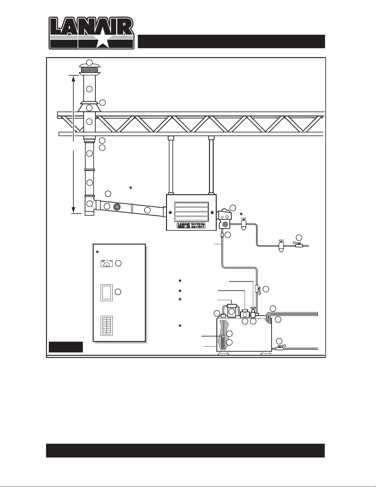
TYPICAL INSTALLATION:
HEATER/CHIMNEY PACKAGE
Through the roof installation
Ceiling Hung
8 ft. min.
10 ft. max.
11
Fuel Line - 1/2” O.D.
Soft Copper
12
Secondary Air Regulator
13
Primary Air Regulator (not supplied)
15
Set to 30 lbs.
Service
Disconnect
Main Power
120v - 60 hz 20 amp
Figure 1
1. Chimney Cap
2. Chimney Pipe (36”)
3. Storm Collar
4. Roof Flashing
5. Chimney Pipe (36")
6. Finishing Collar
7. Slip Connector (14")
8. Black Pipe (24")
9. Black Tee w/cap
22
10. Barometric Damper
11. Black Pipe (24")
12. Burner
13. Union
14.
Tank Vent
15. Shut-off Valve
16. Shut-off Valve
17. Suction Line Strainer
18. Fuel Pump
Oil Bypass Regulator
Pump Assembly
Primary Strainer
1/2” Checkvalve
and Oil
Strainer
Supply Tank
16
17
13
18 25
19
20
14
24
23
19. Check Valve
20. Pick-up Tube Strainer
21. Thermostat
22. Service Disconnect
23. Tank Drain
24. Fill Pipe
25. Oil Bypass Pressure Reg.
★ Included with Heater
QUESTIONS?... Contact Customer Service at 1-888-370-6531 M-F 8:00 am- 4:15 pm CST
10a
Page 12

Section 2 - Heater Install w/ Metering Pump
10 ft.
min.
1
any object within 10 ft.
2
3
4
5
6
7
8
8
10
9
11
Room
Thermostat
Chimney Cap
3 ft. taller than
Class “A” Chimney
Barometric Damper
2-3 ft. away from heater
Chimney Connector
10 foot max. length
1/4” rise per foot of length
21
TYPICAL INSTALLATION:
HEATER/CHIMNEY PACKAGE
Through the roof installation
Ceiling Hung
8 ft. min.
10 ft. max.
11
Fuel Line - 1/2” O.D.
Soft Copper
12
Secondary Air Regulator
13
Primary Air Regulator (not supplied)
15
Set to 30 lbs.
Service
Disconnect
16
14
24
23
Main Power
120v - 60 hz 20 amp
Figure 1
1. Chimney Cap
2. Chimney Pipe (36”)
3. Storm Collar
4. Roof Flashing
5. Chimney Pipe (36")
6. Finishing Collar
7. Slip Connector (14")
8. Black Pipe (24")
9. Black Tee w/cap
22
10. Barometric Damper
11. Black Pipe (24")
12. Burner
13. Union
14.
Tank Vent
15. Shut-off Valve
Metering Pump
Primary Strainer
1/2” Checkvalve
and Oil
Strainer
Supply Tank
17
13
18
19
20
19. Check Valve
20. Pick-up Tube Strainer
21. Thermostat
22. Service Disconnect
23. Tank Drain
24. Fill Pipe
16. Shut-off Valve
17. Suction Line Strainer
18. Fuel Pump
★ Included with Heater
QUESTIONS?... Contact Customer Service at 1-888-370-6531 M-F 8:00 am- 4:15 pm CST
10b
Page 13
Section 2 - Heater Installation
Ductable Applications:
This unit is designed for outlet air ducting applications with .20 inch W.C or less static
pressure. Existing louvers must be removed before attaching ductwork. This unit is not
designed for a return air connection. A qualified heating contractor must design the
ductwork for your installation. Existing ductwork may not meet the requirements of
this furnace.
General Requirements
1.1.Do not install the heater on a combustible surface of any kind. For minimum clearance to
combustible material (see Page 9)
2. Install the heater in a location to utilize total heat throw.
3. Install the heater in a location to permit a correct outdoor chimney exit to eliminate
down drafts, and provide easy chimney installation and maintenance. Class A chimney
MUST be used when passing through any wall or ceiling. See Section 3 Chimney
Installation
4. Install the heater in a location to permit the fuel supply to be as close as possible.
5. Do not install the heater more than 10 feet above the top of the fuel supply tank.
6. Before suspending the heater check the supporting structure and reinforce if necessary
to support the weight of the heater/system.
7. Use 3/8” steel threaded rod to suspend the heater from a capable load carrying ceiling
structure when not using the Lanair Waste Oil Storage Tank.
8. The heater must be suspended level for proper operation. A heater that is not level could
cause a hazardous situation in which personal injury or property damage may result.
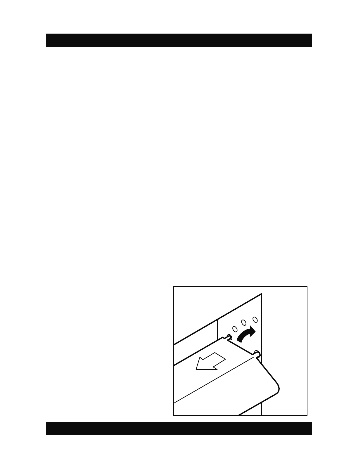
Adjustable Locking Louvers
The MX Series heaters feature spring
loaded locking louvers. To adjust:
• Slowly push the louver to the left
until the locking pin disengages.
NOTE: Do not allow the pivot pin
to come out of the hole.
• Tilt the louver forward/backward
until desired position is obtained.
Pivot Pin.
NOTE: Do not
allow pin to
disengage while
adjusting
• Release louver so locking seats
into the hole.
Visit our website at: www.lanair.com
11
Page 14
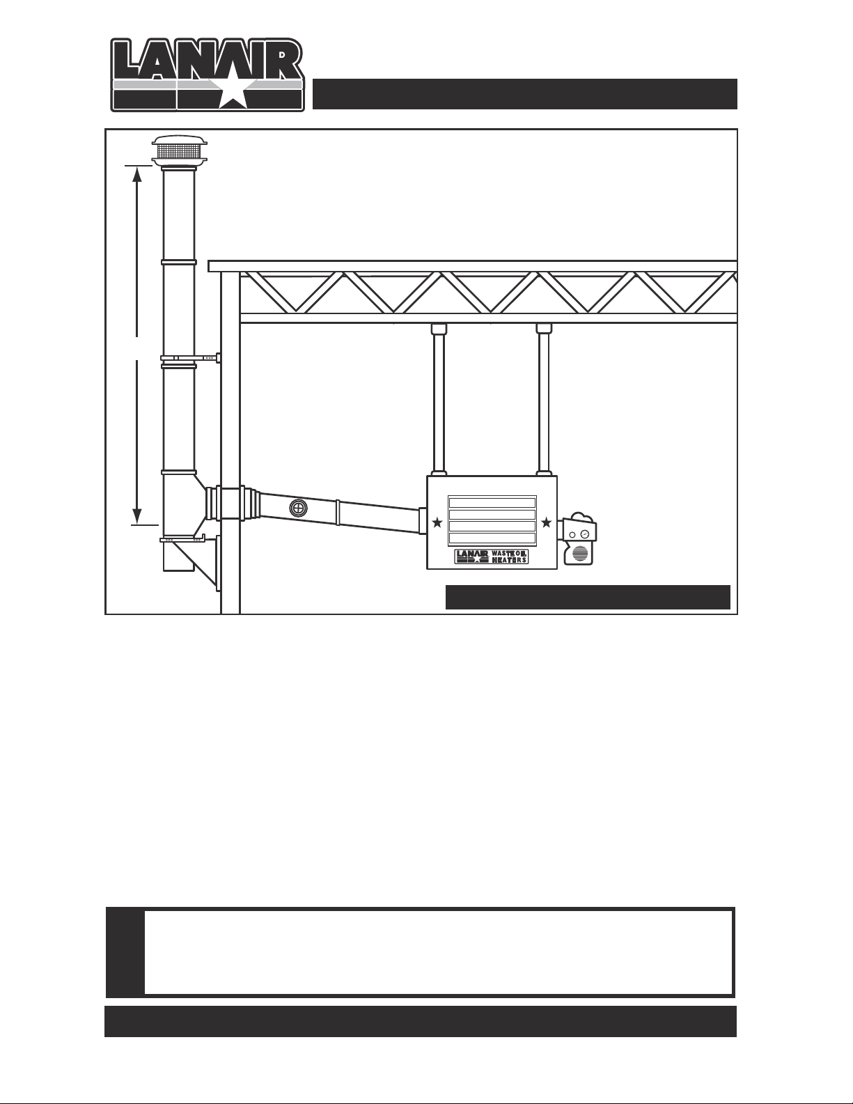
Section 3 - Chimney/Vent System
10 ft.
min.
Chimney Cap
3 ft. taller than
any object within 10 ft.
Class “A” Chimney
Barometric Damper
2-3 ft. away from heater
NOTE: Class "A" components require a 2" clearance
from combustible materials. All other chimney components require a minimum 18" clearance from combustible materials
Ceiling Hung
8 ft. min.
10 ft. max.
Chimney Connector
10 foot max. length
1/4” rise per foot of length
Figure 2 - Typical Chimney Installation
General Requirements
1. Safe operation of any gravity vented heating appliance requires a proper air make-up
system to prevent the heater exhaust gases from being drawn into the building.These
gases could cause death, serious injury, and/or property damage. Exhaust fans, paint
booths may cause draft problems.
2. Never vent this heater into another heating appliances chimney. Never vent into “Class B”
chimney.Gas heaters use “Class B”chimney, it is rated for a much lower temperature than
is required for your waste oil furnace.This heater must have its own separate “Class A”
chimney.
3. Inspect and maintain the chimney on an annual basis.
Failure to provide proper venting of the heater exhaust gases could
result in death, serious injury, and/or property damage. FOLLOW
!
CHIMNEY MANUFACTURERS INSTRUCTIONS.
QUESTIONS?... Contact Customer Service at 1-888-370-6531 M-F 8:00 am- 4:15 pm CST
12
Page 15
Section 3 - Chimney/Vent System
General Requirements (cont.)
4. Install a U.L. listed barometric damper in the chim-
ney. Do not reduce or enlarge the vent pipe.
5. Do not use more than one 90° elbow. Each 90°
elbow equals a 10’ run of chimney.The maximum
run for the chimney connector is 30’.
6. To prevent the drawing of exhaust gases into the
building, keep the barometric draft control at least
24” from the heater, exhaust fan etc..
7. Position the draft control as shown. Barometric
Damper gate pins must be horizontal (Parallel to
the floor) for proper operation.
8. Secure all connections in the chimney connector with 3 screws per joint.
9. The chimney connector clearance to any combustible material is 18”. The “Class A”
chimney clearance to any combustible is 2”. Follow the chimney
instructions.
Barometric Damper Position
HORIZONTAL
VERTICAL
NOTE: Barometric Damper may
be mounted horizontally or
vertically. Angle gate pins
must be horizontal for proper
operation
manufacturer’s
10. Do not install heat re-claimers, manual draft controls, or any other type of restrictive
control in the chimney.
11. Install clean out tee with a cap, at the transition of the chimney. FOLLOW CHIMNEY
MANUFACTURERS INSTRUCTIONS.
12. Use “Class A” insulated chimney pipe to vent exhaust gases through wall, ceilings, attics,
roofs, combustibles, etc. Class A chimney must be used for the entire run once passing
through a wall of ceiling.
13. Vent chimney at least 3 feet above the roof and at least 3 feet higher than any portion
of the building, roof, or obstruction within 10 feet of the chimney.
14. The chimney cap should be at least 3’ above the chimney exit through the roof.
15. Do not use a rotating chimney cap.Use a non-restrictive “Class A” cap made for the type
“Class A”chimney you are using. Follow chimney manufactu
16. The chimney must be capable of producing a negative -.02 W.C. draft when cold and .06 W.C. draft when hot. Refer to Section 4 Draft Instructions. Refer to Section 3.10 for
typical Chimney Installation.
NOTE: Do not install chimney in front of the heater (in air stream of fan)
rer’s instruction.
Visit our website at: www.lanair.com
13
Page 16
Section 3 - Chimney/Vent System
17. If you are unable to attain the proper draft, check for exhaust fans in the building.To test
if there is a problem, open an overhead door and see if you now have the proper draft.
You may have to add one or more sections of “Class A”chimney to the roof to get the
proper draft.
18. The heater and chimney must be installed in accordance with all state and local
codes.The heater must be installed in accordance with the specifications listed in
this manual. The chimney must be installed per the chimney manufacturer’s
instruction. Use “Class A” chimney only.
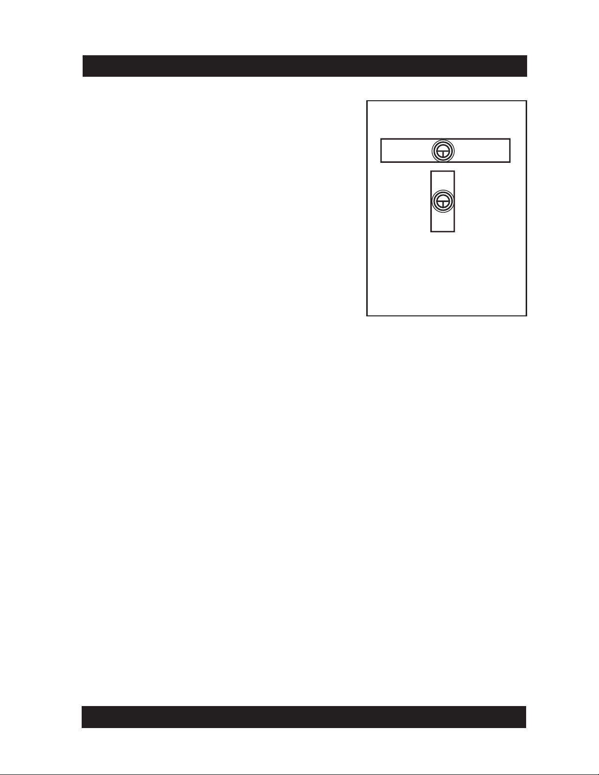
Chimney Configurations Using Top Vent ( not to scale )
Left Exhaust
Install Cap
On Vent
Right Exhaust
Through Roof
Left Exhaust
Through Roof
Install Cap
On Vent
Right Exhaust
Through Wall
Install Cap
On Vent
Install Cap
On Vent
NOTE: If using the top vent, the installed cap must be removed and placed on the side vent
using the screws provided.
QUESTIONS?... Contact Customer Service at 1-888-370-6531 M-F 8:00 am- 4:15 pm CST
14
Page 17
Section 4 - Draft
The Lanair heater should have a (negative) -.02 draft reading when cold,and a (negative) -.06
when hot. Check the heater when it is running after 45 minutes. If the reading is not what it
should be, adjust the barometric damper according to the instructions provided with the
damper.The draft reading should be taken with a manometer.Consult your heating contractor, or a manometer can be purchased from the Lanair Customer Service Department .
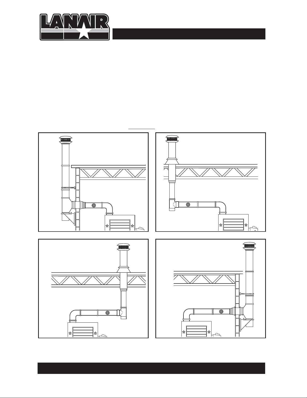
Section 5 - Fuel Supply Tank Install w/ Bypass Regulator
1/2” Copper Tube
(to Burner - not included)
PUMP
ASSEMBLY
(included)
TOP VIEW
Figure 3
9570 By-Pass
Regulator
(included)
9807 Primary Strainer
(included)
8748 Strainer Suction Line
(included)
Tank Drain Plug
1/2” Copper Tube
(to Burner - not included)
8398 Vacuum Guage (included)
1/2” Pick-up Tube
(not included)
8662 Check Valve
(included)
Bottom of strainer must be 6”
from the bottom of the tank
PUMP
ASSEMBLY
(included)
If using a Lanair supply tank follow instructions included with the tank.
!
Visit our website at: www.lanair.com
15a
Page 18
Section 4 - Draft
The Lanair heater should have a (negative) -.02 draft reading when cold,and a (negative) -.06
when hot. Check the heater when it is running after 45 minutes. If the reading is not what it
should be, adjust the barometric damper according to the instructions provided with the
damper.The draft reading should be taken with a manometer.Consult your heating contractor, or a manometer can be purchased from the Lanair Customer Service Department .
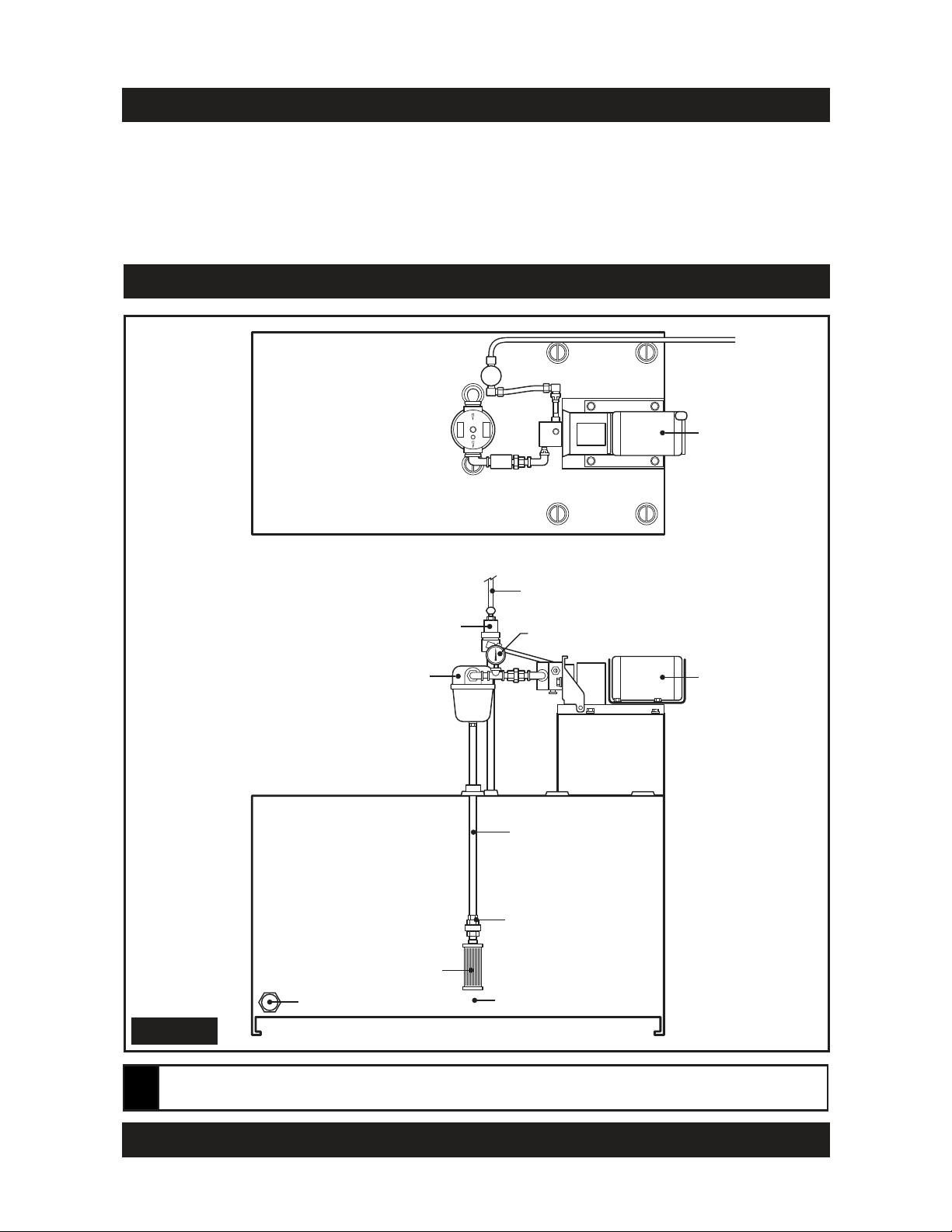
Section 5 - Fuel Supply Tank Install w/ Optional Metering Pump
3/8” Copper Tube
(to Burner - not included)
METERING PUMP
ASSEMBLY
(included)
3/8” Copper Tube
(return to tank - not included)
TOP VIEW
Figure 3
8398 Vacuum Guage (included)
9807 Primary Strainer
(included)
3/8” Copper Tube
(return to tank - not included)
8748 Strainer Suction Line
(included)
Tank Drain Plug
3/8” Copper Tube
(to Burner - not included)
1/2” Pick-up Tube
(not included)
8662 Check Valve
(included)
Bottom of strainer must be 6”
from the bottom of the tank
METERING PUMP
ASSEMBLY
(included)
If using a Lanair supply tank follow instructions included with the tank.
!
Visit our website at: www.lanair.com
15b
Page 19

Section 5 - Fuel Supply Tank Installation
If using a Lanair supply tank follow instructions included with the tank.
!
General Requirements
1. The fuel supply tank and supply lines must be installed in accordance with the National
Fire Protection Association requirements,as well as State and Local ordinances.
2. Regulations require oil storage tanks located inside not too exceed 275 gallons individu-
ally,and are not to exceed a total capacity of 550 gallons in one building. Check State
and Local codes.
3. Locate the fuel supply tank inside the building as close to the heater as possible. It
should be no further than 25 feet from the heater to avoid oil flow problems.
4. The fuel supply tank must be mounted below the burner and the by-pass regulator (or
supply pump assembly when using the optional metering pump). Mounting the fuel
supply tank above the burner will create head pressure and over-fire the burner voiding
the warranty.
5. Pitch the fuel supply 2º with the drain valve at the lowest end to drain off water and
sludge. Sludge may have to manually be removed.
6. Some ordinances may require the fuel supply tank to be vented to outside
and
above the roofline.Check State and Local codes. Keep the vent clear.
7. Install the fuel tank fill pipe at the end of the tank and above the drain.
8. Label the fuel tank for the recommended fuels.
9. Strain all fuel with a 50 X 50 mesh strainer before putting fuel into the tank.
10. When filling the fuel tank with a motorized pump,never leave unattended to prevent
over filling and/or spillage.
11. Keep cap on the fuel tank when not filling.
For optimum performance, the waste oil pump manufacturer recommends that multi-weight oils such as 5W-30W be maintained at 32˚ F
!
minimum and straight weight oils such as 40W and 50W be maintained
at 50˚ F minimum.
QUESTIONS?... Contact Customer Service at 1-888-370-6531 M-F 8:00 am- 4:15 pm CST
16
Page 20

Section 6 - Fuel Supply Pump/Piping
General Requirements
1. Mount the fuel supply pump in a horizontal position (shaft horizontal) near the fuel sup-
ply tank.
2. The oil pump has a maximum suction lift of 14 feet. Suction lift is the length of pipe run
from the bottom of the pick-up strainer to the fuel supply pump.
3. The fuel pump/motor are intended for indoor use only.
4. The fuel pump contains an internal strainer that periodically needs to be cleaned.This
internal strainer is mounted behind the pump cover. Before removing the pump cover
make sure you have a new gasket on hand. Contact the Lanair Customer Service
Department for the proper gasket for your model of pump, at 1-888-370-6531.
5. Install the suction supply line from the inlet side of the fuel pump into the fuel tank
opposite the drain.
6. Install a 1/2” inside diame
out the suction supply line and pick up tube. The use of smaller line, or rubber, plastic or
hydraulic line is unsafe and will void your warranty.
7. Use thread sealing compound on all pipe thread connections. Do Not Use Teflon Tape.
8. Install the suction line strainer in the suction line. Make sure the suction line strainer is 6”
off the bottom of the tank. The suction line strainer may be mounted horizontally or vertically.Consider accessibility.
9. Install a 1/2” NPT pipe union between the suction line strainer and the pick up tube to
allow for service on the pick up tube.
10. Install the check valve (arrow facing towards the pump) on the bottom of the pick up
tube.
11. Install a vacuum gauge in the suction line.This gauge will indicate when service
ed on the strainer, pump or connections.
12.
When using a by-pass regulator install a 1/2” inside diameter (.493) steel pipe, or 1/2”
outside diameter copper from the fuel by-pass regulator (port marked “T”) to the fuel
supply tank. Do not allow this line to protrude into the tank more than 1”. The use of
smaller line, or rubber, plastic or hydraulic line is unsafe and will void your
warranty.
ter (.493) steel pipe, or 1/2” outside diameter copper through-
is need-
When using the optional Metering Pump install a 3/8” copper line from the tee on the
metering pump assembly to the fuel supply tank do not allow this line to protrude
below the level of the oil. The use of smaller line, or rubber, plastic or hydraulic line is
unsafe and will void your warranty.
13. Do not allow the fuel level in the tank to cover the return line.
Visit our website at: www.lanair.com
17
Page 21

Section 6 - Fuel Supply Pump/Piping
14.
When using a by-pass regulator install the fuel supply line from the fuel by-pass regulator
(port B) to the inlet port on the left side of the burner using 1/2” inside diameter (.493)
steel pipe, or 1/2” outside diameter copper tubing. The maximum distance of this line is 25
feet. The fuel supply line must be run below the burner at all times. If the fuel supply line
runs above the burner it will create head pressure. This head pressure will over-fire the
burner voiding the warranty.
When using the optional metering pump install the fuel supply line from the pump
assembly to the burner (see diagram on page 10b).
15.
Install a union in the supply line close to the burner for service.
16.
install a shut-off valve in the fuel supply line for service.
17.
If using copper line on the suction side of the pump use 37º flare fittings on all copper
tubing connections. Do not use compression fittings.
18.
Keep the fuel supply lines 1” off any outside walls.
19.
The fuel supply line must gradually rise to the burner. It should not be higher than
the burner.
20.
Clean all lines, fittings, and parts internally before assembly. A small burr or piece of
rust could plug the nozzle. See Section 2 for an illustration of a typical pump and piping
installation.
When using the optional metering pump skip to Section 7
B.
Port to the oil inlet on the burner assembly.
Install 1/2” O.D. min. copper tubing, or 1/2”
schedule 40 pipe. Failure to install this line
properly will result in damage to your heater,
and will void your warranty.
T.
Port to the oil supply tank for the overflow
return line. Install 1/2” O.D. min. copper
tubing. or1/2“ schedule 40 pipe. This line
MUST run straight into the tank, and
should not be sub-merged in oil. No
elbows should be used. Failure to install
this line properly will result in damage to
your heater, and will void your warranty.
P.
Port from the outlet side of your fuel supply
pump. Install 1/2” O.D. min. copper tubing, or
1/2 schedule 40 pipe. Failure to install this
line properly will result in damage to your
heater, and will void your warranty.
Bottom View of the Aluminum Oil
By-Pass Regulator
Figure 4
QUESTIONS?... Contact Customer Service at 1-888-370-6531 M-F 8:00 am- 4:15 pm CST
18
Page 22

Section 7 - Air Supply Installation
General Requirements
1. Install an air pressure supply line connection to the air filter/regulator on the rear of the
heater.
2. The air supply source must be capable of producing 2.0 CFM @ 60 PSI.
3. Install a shut off valve in the air supply line for service.
4. Install a primary air filter/regulator with a gauge (capable of reading line pressure) in the
air supply line prior to the air filter/regulator mounted on the furnace.The primary air filter/regulator is not supplied with the furnace.
5. If the primary air regulator does not have a filter with a bowl, a condensate drain leg
must be installed in the air supply line.
6. Install a quick disconnect at the air filter/regulator on the furnace for service.
7. For the ease of installation install a flexible airline (.250 I.D.minimum) from the quick
disconnect to the primary air regulator.
8. The air supply line must be pitched uphill from the primary regulator to the furnace to
prevent condensation from entering your burner.
9. Open all air shut off valves, and set the primary air regulator at 30 PSI.
10. Set the air filter/regulator on the front of the furnace to 18 LBS. See illustration below
(Fig.5) for a typical air pressure supply installation.
Figure 5
secondary air filter/
regulator (included)
15
10
5
20
25
air inlet
bottom of burner
to primary air filter/regulator (not included)
and air supply
Visit our website at: www.lanair.com
19
Page 23

Section 8 - Electrical Connections
!
CAUTION: HAZARD OF ELECTRICAL SHOCK!
Main Electrical Installation
1. All wiring must comply with the National Electrical Code. State and Local Ordinances,
and be wired by a qualified electrician.
2. Electrical service MUST BE CONNECTED TO TWO SEPARATE 20 AMP, 115 VAC, 60
HZ single phase circuits.
3. Electrical service connections are made in the electrical junction box on the side of the
heater.
4. The heater must have a safety equipment ground from the main electrical service,
stranded 12 GA minimum.
5. The electrical conductors for electrical service to the heater MUST be stranded 12 GA
minimum.
6. Install a manual service disconnect near the heater, and label its function.
7. The supply voltage must be maintained at a minimum 110 VAC.
8. The electrical conductors from the main electri-
cal service must be within approved conduit.
9. Keep all electrical conductors and conduit away
from the chimney connector as well as any
other hot surfaces. Refer to Figure 7, Wiring
Diagram for color code, etc. Keep the
until the heater is ready to be started. Refer to
Section 12 Start Up Procedure.
power off
Remove wires from the block by inserting a small flat tip screwdriver into the
top slot. Push tip all the way down and
push forward. Remove wire.
Figure 6
QUESTIONS?... Contact Customer Service at 1-888-370-6531 M-F 8:00 am- 4:15 pm CST
20
Page 24

Lanair Pump Motor Electrical Connections
Provided by Installer
Figure 7
LINE IN +
LINE IN -
CIRCUIT
120V 20 AMP
CUST. SUPPLIED
WHITE/YELLOWBLUE
NAF
TIMIL / NAF
LORTNOC
WHITE
ETIHW
RED
ORANGE
LINE IN +
LINE IN -
ROTOM
PMUP
WHITE
RED
BLUE
ETIHW
BLUE
FAN
PURPLE
BLACK
MOTOR
ETIHW
TIMIL
BLUE
DIONELOS
RIA
EGNARO
ELPRUP
White Rodgers
TIMIL / NAF
LORTNOC
Honeywell
YELLOW
WHITE/BLACKRED
BLACK
LIMIT
FAN
RED
DER
RED
BLUE
BLUE (NOT USED)
WHITE
WHITE
WHITE
WHITE
BLACK
SWITCH
PRE-HEATER
RETAEH-ERP
LIO
RETAEH-ERP
RIA
PANS
KSID
KCALB
LAUNAM
TESER
REMROFSNART
BLACK
WHITE
NOITSUBMOC
REWOLB
ETIHW
TATSOMREHT
LLAW
LLEC
DAC
YELLOW
YELLOW
2F 1F 2T 1T
KCALB
YRAMIRP LIO
WHITE
ORANGE
Visit our w ebsite a t : ww w .lanai r . c om
21a
Page 25

Lanair Metering Pump Electrical Connections
Provided by Installer
Figure 7
LINE IN +
LINE IN -
BLACK
RED
CIRCUIT
120V 20 AMP
CUST. SUPPLIED
CAPACITOR
GEAR
MOTOR
WHITE/YELLOWBLUE
NAF
TIMIL / NAF
LORTNOC
WHITE
ETIHW
RED
ORANGE
GREEN
LINE IN +
LINE IN -
BLACK
BLACK
BLUE
GREEN
WHITE
RED
BLUE
ETIHW
BLUE
FAN
PURPLE
BLACK
MOTOR
ETIHW
TIMIL
BLUE
DIONELOS
RIA
EGNARO
ELPRUP
White Rodgers
TIMIL / NAF
LORTNOC
Honeywell
YELLOW
WHITE/BLACKRED
BLACK
LIMIT
FAN
RED
DER
RED
BLUE
BLUE (NOT USED)
WHITE
WHITE
WHITE
WHITE
BLACK
SWITCH
PRE-HEATER
RETAEH-ERP
LIO
RETAEH-ERP
RIA
PANS
KSID
KCALB
LAUNAM
TESER
REMROFSNART
BLACK
WHITE
NOITSUBMOC
REWOLB
ETIHW
TATSOMREHT
LLAW
LLEC
DAC
YELLOW
YELLOW
2F 1F 2T 1T
KCALB
YRAMIRP LIO
WHITE
ORANGE
Visit our w ebsite a t : ww w .lanai r . c om
21b
Page 26

Section 8 - Electrical Connections
CAUTION: HAZARD OF ELECTRICAL SHOCK!
!
Fuel Supply Pump Electrical Installation
1. All wiring must comply with the National Electrical Code, State and Local Ordinances,
and be wired by a qualified electrician.
2. The electrical conductors to the fuel pump motor MUST be stranded 14 GA minimum.
3. The electrical service connections for the fuel pump motor are made in the electrical
junction box on the side of the heater.
4. The pump motor MUST have a safety equipment ground from the main electrical serv-
ice, stranded 14 GA minimum.
5. The electrical conductors from the electrical junction box to the pump motor must be
within approved conduit.
6. Keep all electrical conductors and conduit away from the chimney connector as well as
any other hot surfaces. Refer to Figure 7 Wiring Diagram for color code, etc. Keep the
power off until the heater is ready to be started. Refer to Section 11 Start Up Procedure.
Room Thermostat Installation
1. All wiring must comply with the National Electrical Code, State and Local Ordinances,
and be wired by a qualified electrician.
2. Install the room thermostat in accordance with the directions furnished with the ther-
mostat.
3. Use two conductor thermostat wire for the connection of the thermostat to the T.T. ter-
minals of the oil primary control that is mounted on top of the burners electrical box.
4. Mount the thermostat 5 feet above the floor on an inside wall away from the heater’s
warm air path.
5. The electrical current for thermostat is 24 V, and is provided by the oil primary control.
6. Keep the thermostat wire away from the chimney connector, or any other hot surfaces.
Refer to Section 2 for a typical thermostat installation.
QUESTIONS?... Contact Customer Service at 1-888-370-6531 M-F 8:00 am- 4:15 pm CST
22
Page 27

Section 9 - Controls
s Room Thermostat:
The room thermostat automatically controls the on/off operation of the heater according
to the setting of the desired room temperature.The thermostat works in conjunction with
the oil primary safety control.
s Oil Primary Safety Control/Cad Cell:
The oil primary control is mounted on top of the burner’s electrical box.When the thermostat calls for heat the oil primary control starts the burner by switching on the air solenoid
valve, ignition transformer, combustion air blower, and the fuel pump.The oil primary control works in conjunction with the cadmium sulfide cell (cad cell). The cad cell is mounted
inside the burner cover, and faces the flame.The cad cell monitors the light level inside the
combustion chamber to insure there is a flame present. If there is a loss of flame the primary control will go into its recycle mode. After 1-2 minutes the primary control will restart
the burner.When this happens if there is a flame present, the burner will continue to function. If on start-up no flame is established in 30 seconds the primary control will lock out.
CAUTION: Do not press the reset button more than twice. If the burner fails to start refer to
Section 14 - Trouble Shooting. Burner has a (2) minute automatic restart feature.
s Fan/Limit Control
The fan/limit control performs 3 functions. The fan/limit control monitors the temperature
of the air inside the cabinet. When the air reaches a set point (usually 120º F) it will switch
on the heater fan.When the temperature in the cabinet drops below 90º F the fan/limit
control will turn the fan off.The Fan/Limit Control contains
the axial fan on manual by-passing its automatic function.
The Fan/Limit Control monitors the temperature of the air inside the cabinet. When the
temperature exceeds a fixed set point it switches the burner (Oil Primary Control) off until
the temperature drops to a safe level.The burner will then restart.
“CAUTION”This means the heater has reached its “High Limit”, the cause must be determined and corrected before further use (over firing the unit is normally what causes this
condition). The Fan/Limit Control is located on the top on the front of the cabinet.
an external slide switch to turn
s Barometric Draft Control
The Barometric Draft Control automatically maintains a pre-set chimney draft, and is located in the chimney connector.
s Air Filter/Regulator
The Air Filter/Regulator performs two functions: It removes condensation and dirt from the
air.and it controls the amount of air pressure reaching the nozzle and air operated fuel
valve.The Air/Filter Regulator is mounted on the cabinet near the burner.
Visit our website at: www.lanair.com
23
Page 28

Section 9 - Controls
s Electric Air Solenoid Valve
The Electric Air Solenoid Valve is controlled by the Oil Primary Control. It acts as a shut-off
valve, (it’s open during operation, and closed when the burner is off). The Electric Air
Solenoid Valve is located inside of the burner’s electrical box. (See Page 51).
s Air Operated Fuel Valve
The Air Operated Fuel Valve controls fuel flow out the nozzle.When the Electric Air
Solenoid Valve opens and air pressure pushes on the fuel valve diaphragm, the plunger
moves off the nozzle seat allowing fuel to enter the nozzle. The Air Operated Fuel Valve is
located on the back of the air pre-heater. (See Page 51).
s Air/Oil pre-heater
The Air/Oil pre-heater is an assembly that preheats the atomizing air and fuel to a predetermined temperatu
burner (See Page 51).
s Snap Disc
The Snap Disc accurately controls the temperature of the air/oil pre-heater assembly with
two resistance type cartridge-heating elements. The Snap Disc is mounted on the oil preheater inside the burner. (See Page 51).
re to properly combust used oil. The Air/Oil pre-heater is located in the
s Nozzle
The Nozzle uses air pressure to help pull fuel through its small orifice, and to atomize the
fuel for proper combustion.The Nozzle is located on the end of the air pre-heater opposite
the fuel valve. Replace the Nozzle annually, as they are prone to wear by contaminants in
waste oil (See Page 47).
s Fuel By-Pass Regulator (This is not used with the Optional metering pump)
The Fuel By-Pass regulator controls the pressure of the fuel to the nozzle. The Fuel By-Pass
regulator is located in the line between the outlet side of the pump and the burner.
s Fuel Supply Pump
The Fuel Supply Pump pumps fuel from your oil storage tank to the burner. The Fuel Supply
Pump should be located as close to the fuel supply tank as possible. The Fuel Supply Pump
must be mounted horizontally (Shaft).
s Optional Metering Pump Assembly
The metering pump pumps fuel from your oil storage tank to the burner. It also controls the
volume of fuel, and no regulator is required. The metering pump should be mounted on
your fuel supply pump with the shaft in the horizontal position.
QUESTIONS?... Contact Customer Service at 1-888-370-6531 M-F 8:00 am- 4:15 pm CST
24
Page 29

Section 10 - Priming The Fuel Pump
Priming The Fuel Pump
1.
The fuel level in the supply tank must be
above the check valve on the pick-up tube.
2.
Remove the bowl of the suction line strainer,
and fill with clean fuel. Replace the strainer
bowl.
3.
Remove the two yellow wires from the F-F
terminal on the oil primary control. Install a
jumper wire between the F-F terminals (see
Figs. 8 & 9).
4.
Adjust the air filter/regulator on the heater to
18 PSI.
5.
Remove the fuel supply line from the burner,
and position a container to catch the fuel.
6.
When using the by-pass regulator, back the
thumb screw out (CCW) on the by-pass
regulator until it is free, the turn (CW) two
turns to seat the diaphragm.
7.
Loosen the bleeder screw on the pump one
turn, and attach a piece of 3/16” ID clear plastic
tubing. The tubing should be long enough to
allow the fuel to be returned to the tank.
Figure 8
Remove two yellow wires
Figure 9
8.
Turn the room thermostat above room
temperature, or to the “ON” position.
9.
Momentarily disconnect one end of the
jumper wire at the F-F terminals on the oil
primary. The fuel pump will now start.
Observe the clear tubing attached to the bleeder screw on the pump. When a steady
10.
stream of fuel (no air bubbles) flows close the bleeder screw. Remove the tubing from the
bleeder screw.
Observe the end of the fuel supply line that is disconnected from the burner. Allow a
11.
steady stream (no air bubbles) of fuel to flow into the container for several minutes. This
will flush any debris from the fuel line that could potentially plug the nozzle. The vacuum
gauge reading should not exceed 5” HG of vacuum.
Turn the room thermostat below room temperature or “OFF”. The fuel supply pump will
12.
now stop.
Reconnect the fuel supply line to the burner.
13.
Remove the jumper wire from the F-F terminals on the oil primary control, reattach the
14.
yellow cad cell wires.
Visit our website at: www.lanair.com
Install jumper wire
25
Page 30

Section 10 - Priming The Fuel Pump
12. Turn the room thermostat below room temperature or “OFF”. The fuel supply pump will
now stop.
13. Reconnect the fuel supply line to the burner.
14. Remove the jumper wire from the F-F terminals on the oil primary control, reattach the
yellow cad cell wires.
15. Adjust the burner air filter/regulator to 18 PSI.
16. If the fuel supply pump prime, or fuel stream has air in it (spurting, fluctuating flow) there
is likely a leak in the suction side of the plumbing. Refer to section 14, trouble-shooting,
flow chart #2. The burner should now be ready to fire.
QUESTIONS?... Contact Customer Service at 1-888-370-6531 M-F 8:00 am- 4:15 pm CST
26
Page 31

Section 11 - Burner Start-Up Procedure
Waste Oil Burner Start-Up
1. Make sure the main electrical service for the heater is turned off, and locked out.
2. Fill the oil supply tank with an approved fuel to a level that is above the pick-up tube
check valve.
3. Check for proper draft in the chimney. The draft must read -.02 W.C. cold.
4. Make sure there is air pressure at the heaters air filter/regulator, set at 18 PSI. Set the pri-
mary regulator on the air supply line to 30 PSI.
5. Set the fan/limit control slide switch to automatic.
6. Check the combustion air adjustment baffle for proper setting. Refer to Section 15 Flame
adjustment.
7. Set the room thermostat below room temperature (OFF).
8. Push the reset button on the oil primary control for 3 seconds.
9. Turn the main electrical service ON.
10. Flip the lighted rocker switch for preheating on the burner electrical box to the ON posi-
tion (pre-heater OFF the
11. Prime the fuel supply pump. Refer to Section 10, Priming the Fuel Supply Pump.
If using waste 5W-50W oil, flip the pre-heater rocker switch on (light ON, and wait 5-7
12.
minutes for the pre-heater assembly to reach operating temperature; leave the
pre-heater switch OFF if using No. 1 or No. 2 fuel oil).
Turn the room thermostat up above the room temperature. The burner will now fire,
13.
check the sight glass on the rear of the burner also inspect the flame through the
inspection port. (See page 29-31, flame adjustment).
14. Adjust the burner air filter/regulator to 18 PSI, and the primary air regulator to 30 PSI.
NOTE: 18 PSI on the air filter/regulator is the starting point, you may need to adjust from
there when VISUALLY SETTING THE FLAME (See page 29-31, flame adjustment).
light is off, pre-heater ON the light is on.).
Visit our website at: www.lanair.com
27
Page 32

Section 11 - Burner Start-Up Procedure
15. When using the by-pass regulator adjust the fuel pressure gauge on the left side of the
burner to read.
No. 1 & No. 2 Fuel Oil Approved Waste Oil
Model MXD-200 3.0-3.25 LBS. 2.5-2.75 LBS.
NOTE:
and counter clockwise to decrease pressure to the burner.The oil pressures listed above are a
starting point, you may need to adjust from there when VISUALLY SETTING THE FLAME
(See page 29-31, flame adjustment).
NOTE: When using the metering pump the fuel flow is determined by the pump. Pressures
may not be the same as shown above.
16. Adjust the barometric damper to obtain a draft of -.06 W.C. while the heater is hot and
NOTE: It is VERY IMPORTANT that the barometric damper is set to the required settings to
ensure the natural draft of exhaust gases (see section 4).
17. Depending on the type of fuel used,the elevation, temperature,and oil viscosity, the
18. When the room thermostat setting is met
Adjust the thumb screw on the fuel bypass regulator clockwise to increase pressure,
operating.
combustion air baffle will need to be adjusted for optimum performance (S
31, flame adjustment).
Clockwise:
the burner will shut off, but the fan will continue to operate until the cabinet temperature drops to 90º F.
Increase fuel
pressure
ee page 29-
Counter
Clockwise:
Decrease fuel
pressure
Thumb Screw
Fuel By-Pass Regulator
Not used with the optional Metering Pump
!
QUESTIONS?... Contact Customer Service at 1-888-370-6531 M-F 8:00 am- 4:15 pm CST
The combustion air baffle is NOT factory set
28
Page 33

Section 12 - Flame Adjustment
Flame Adjustment
1. Start the heater, let it run for at least 15 minutes to reach operating temperature before
proceeding.
2. Check the chimney draft, set the barometric damper to -.06 WC when hot and running.
3. Check the atomizing air pressure, set the air filter/regulator on the heater to 18 PSI as a
starting point.
4. When using the by-pass regulator check the fuel pressure gauge on the burner, set to:
Model MXD-200
No. 1 and No. 2 Fuel Oil
Used Crankcase Oil 10W-50
When using the by-pass regulator adjust the thumb screw on the fuel by-pass regulator.
5.
Lock into position. The flame should extend no more than 3/4 of the way into the
chamber. When using the optional metering pump the flow is determined by the
metering pump. Pressures may vary from those listed above.
NOTE: The above pressure is a staring point, depending on your installation you may
need further adjustment. Always VISUALLY SET THE FLAME. See page 30.
6. Loosen the combustion air adjustment
baffle, slowly close the baffle in 1/16”
increments until the heater (flame) starts
to rumble.Then slowly open the baffle in
1/16” increments until the rumbling stops,
(wait 2 minutes between adjustments)
finally open the baffle an additional 1/8”
to provide excess oxygen
fle, (See Fig. 10).
. Secure the baf-
Figure 10
3.0-3.25 LBS
2.5-2.75 LBS
NOTE: Mechanical equipment like gauges
and regulators are not always 100 percent
accurate, VISUAL INSPECTION OF THE
FLAME IS REQUIRED in order to properly
dial in the flame settings, see page 30.
The combustion air baffle is NOT
factory set
!
Visit our website at: www.lanair.com
combustion
air baffle
29
Page 34

Section 12 - Flame Adjustment
NOTE: ALWAYS WEAR EYE, FACE AND BREATHING PROTECTION AND
PROTECTIVE CLOTHING WHEN INSPECTING OR ADJUSTING FLAME.
!
Lift the inspection port cover on the front of the combustion chamber to observe the flame.
The flame tips should extend 3/4 of the way into the combustion chamber. When the unit is
adjusted properly the ash inside the chamber will be white to off white.
Flame tips touching the target brick (end of the chamber) will cause combustion chamber
damage.This condition may be caused by a worn nozzle, or excess burner fuel pressure.
When this condition exists, the ash in the chamber will
be brown to black.
Flame Adjustment - Visual
Flame is over-red (Fig. 11).
t%BSLZFMMPXUPPSBOHFJODPMPS
t5IFøBNFJTIJUUJOHUIFXBMMTöMMJOHUIFDIBNCFS
XJUIBTNPLFZøBNF$PSSFDUJNNFEJBUFMZPSDIBNCFS
NBZCFEBNBHFE
t%FDSFBTFGVFMQSFTTVSFXIFOVTJOHBCZQBTT
SFHVMBUPSBOEBEKVTUDPNCVTUJPOBJS0QFOUIF
DPNCVTUJPOBJSCBõFPOUIFTJEFPGUIFCVSOFS"JS
QSFTTVSFNBZBMTPOFFEUPCFBEKVTUFE
BAD FLAME
The flame is too big, creating an overfire condition
Figure 11
Problem:5PPMBSHFPGBøBNFEBSLZFMMPXJODPMPS
1. 5PPNVDIGVFMQSFTTVSFPOMZXIFOVTJOHBCZQBTT
SFHVMBUPS
2. /PUFOPVHIDPNCVTUJPOBJS
3. /PUFOPVHIBUPNJ[JOHBJSQSFTTVSF
4. 0QFODPNCVTUJPOBJSCBõFPOUIFTJEFPGUIF
CVSOFS
5. "TIJOTJEFUIFDIBNCFSJTEBSLCSPXOUPTPPUZ
CMBDLJODPMPS
Flame is under-red (Fig. 12)
t5IFøBNFJTMJLFBCMPXUPSDI
t-JHIUZFMMPXUPXIJUFJODPMPS
t$IFDLUPTFFJGQSFIFBUFSCMPDLJTIPU
t$IFDLBJS14*JUNBZCFUPPIJHI"EKVTUJO-#
JODSFNFOUT
t0JMQSFTTVSFPOMZXIFOVTJOHBCZQBTTSFHVMBUPS
5IFDPNCVTUJPOBJSCBõFNBZOFFEBEKVTUNFOU
Figure 12
BAD FLAME
The flame is too short
Figure 13
GOOD FLAME
The flame length is approximately 3/4
of the chamber
QUESTIONS?... Contact Customer Service at 1-888-370-6531 M-F 8:00 am- 4:15 pm CST
30
Page 35

Section 12 - Flame Adjustment
Problem: Too small a ame, similar to a blowtorch.
1. Too much atomizing air pressure.
2. Too much combustion air pressure.
3. Not enough fuel pressure when using a by-pass regulator.
Solutions:
1. Correct fuel pressure setting when using a by-pass regulator.
2. Flame tips reach 3/4 of the way into the chamber.
3. Flame has slightly yellow/orange tips.
4. No black smoke coming from the chimney.
5. Ash inside the chamber is white to o white in color.
6. Open combustion air bae on the side of the burner.
Flame is full (Fig. 13).
Bright yellow in color.
Flame extends 3/4 into the chamber.
Flame is not impinging on the chamber walls.
If you need assistance with ame adjustment, please call Lanair's Parts and Service
Department.
DO NOT OVER FIRE YOUR HEATER. IMMEDIATELY ADJUST
THE BURNER TO THE PROPER FLAME LENGTH TO PREVENT
!
DAMAGE TO YOUR HEATER.
CHECK FLAME DAILY (see page 30). ADJUST ACCORDINGLY
!
Visit our website at: www.lanair.com
31
Page 36

Section 13 - Service / Maintenance
MX SERIES HEATER SERVICE / MAINTENANCE SCHEDULE
DAILY
s Check fuel supply
tank level (pre-strain
all fuels).
s Check vacuum gauge
reading on suction
line. See Section 19.
s Check atomizing air
pressure at the air filter/ regulator.Set to
18 psi. Drain water
from the bowl if necessary
s Check the fuel pres-
sure gauge on the
burner.Set to the
correct pressure for
the fuel being used.
s Visually inspect
flame. Adjust accordingly.NOTE: Wear
adequate eye,face
and breathing protection.
s Check draft using a
manometer.Set draft
to -.02 cold, -.06 hot.
s If heater is not to be
used for more than
48 hours (overnight)
flip the pre-heater
rocker switch off
(light off ).
WEEKLY
s Drain water/ anti-
freeze from the fuel
supply tank.
s Check the air pres-
sure setting on the
primary air regulator.
Set to 30 psi.
s Drain water from the
air pressure supply
line drain leg and primary regulator.
s Inspect the combus-
tion, ash build-up
and flame.
NOTE: Wear adequate eye,face and
breathing protection.
MONTHLY
s Check combustion
chamber and heat
exchanger. Clean if
neccessary. Inspect
fire brick.
NOTE: Wear protective clothing,adequate eye,face and
breathing protection. Do not breathe
dust from the combustion chamber.
Wash thoroughly
with soap and
water after cleaning
chamber.
s Clean the chimney,
chimney connector
and barometric
damper.
s Clean pump strainer,
suction line strainer
and pick-up tube
strainer (pp 38).
NOTE: Always prime
pump after cleaning
strainers.
s Check for dirt build-
up on the combustion blower wheel.
Keep wheel clean.
ANNUALLY
(Season Shut Down)
s Shut off main power
supply to heater.
s Perform monthly
service/maintenance.
s Flip air/fuel pre-
heater switch off.
s Shut off air supply.
s Remove air/fuel pre-
heater assembly.
Disassemble and
clean (pp. 34, 35).
s Remove air turbula-
tor and clean (pp. 33)
s Replace nozzle and
quad ring (pp. 34, 35,
39)
s Replace Ignitor (pp
39).
s Adjust turbulator (pp
39).
s Lubricate all
following specifications on the motor
rating plate.
s Clean fuel pump
strainer (see pp 38).
s Drain and clean fuel
supply tank.
motors
s Clean combustion
blower, axial fan
blades and fan cage
QUESTIONS?... Contact Customer Service at 1-888-370-6531 M-F 8:00 am- 4:15 pm CST
32
Page 37

Air Pre-Heater Breakdown
Section 13 - Service / Maintenance
02
51
91
81
41
31
9
7
8
5
6
71
61
11
01
32
21
See pages 36-37 for required
annual oil block maintenance
22
4
3
2
1
This entire pre-heater assembly is available.
Part# 9812
(For a Tune-Up)
Visit our website at: www.lanair.com
33
Page 38

Maintenance - Air Pre-Heater
Section 13 - Service / Maintenance
1. Remove Pre-Heater Assembly
s Disconnect the air line from the
brass fitting on the air pre-heater
and then from
the air solenoid and remove.
s Disconnect wiring from the oil pre-
heater cartridge, air pre-heater
cartridge and snap disc assembly in
the wiring junction box.
s Disconnect fuel line and fitting (6)
from the oil block (5).
s Disconnect fuel pressure gauge (8)
and fitting from the oil block (5).
s Remove button hex screw (14) and
washer (11).
s Lift pre-heater assembly and care
fully pull straight back. Remove
entire assembly from the burner.
s Remove ignitor assembly (6).
2. Remove Diaphragm Assembly
from Air Pre-Heater
s Carefully place pre-heater assembly
in a vice. NOTE: Do not damage
pre-heater.
s Unscrew diaphragm assembly (19)
from air pre-heater and set aside.
Remove o-ring.
Ref. Part
No. No. Qty. Description
1 9853 1 turbulator
2 - 1 set screw
3 9899 1 nozzle Heater
4 - 1 quad ring
5 9814 1 air pre-heater block
6 3728 1 ignitor assembly
7 - 1 hex cap screw
8 - 1 flat washer
9 - 1 connector
10 - 1 1/4" o-ring
11 - 1 11/16" o-ring
12 9549 1 air cartridge heater
13 - 1 spring
14 - 1 viton insert
15 - 1 plunger
16 - 1 adapter block assembly
17 - 1 hex head cap screw
18 - 1 1/2" o-ring
19 - 1 diaphragm assembly
20 - 1 hex head cap screw
21 - 1 oil pre-heater block
3. Remove Adapter Assembly
s Remove hex cap screws (17) and set adapter
assembly aside.
4. Remove Plunger , S
s Remove spring (13) from plunger (15) and clean
both pieces.
s Remove 1/4" o-ring (10) and 11/16" o-ring (11).
s Loosen and remove cartridge heater and set aside.
5. Remove Nozzle Assembly and Quad Ring
s Remove nozzle assembly (3) using a 5/8" wrench.
s If quad ring (4) does not come out with nozzle, care
fully remove it.
QUESTIONS?... Contact Customer Service at 1-888-370-6531 M-F 8:00 am- 4:15 pm CST
pring and Cartridge Heater
Remove wires from the block by
inserting a flat tip screwdriver into the
top slot. Push tip all the way down
and push forward. Remove wire.
34
Page 39

Section 13 - Service / Maintenance
Maintenance - Air Pre-Heater
6. Clean all parts using a parts washer
s All passages must be thoroughly cleaned with a brush.
7. Replace Nozzle Assembly and Quad Ring
s After cleaning air pre-heater assembly, blow dry.
s Install new quad ring (4). Before inserting quad ring in air pre-heater block, a light coat
of oil should be applied. NOTE: Make sure quad ring is properly seated in block before
proceeding (see page 40 for clarification).
s Apply a light coat of oil to the shaft of the new nozzle assembly (3). Carefully insert new
nozzle assembly (3) through the quad ring and into the block. Hand tighten gently.
s Check alignment of ignitors and adjust if necessary (see page 39).
8. Re-install O-rings and Plunger
s Insert 1/4" o-ring (10) and 11/16" o-ring (11) into the air pre-heater block (5).
s Insert plunger
9. Re-install Cartridge Heater
s Apply pipe dope to cartridge heater threads. Insert cartridge heater into air pre-heater
block and tighten.
10. Re-install Adapter Assembly
s Align the holes of the adapter assembly (16) with those on the air pre-heater block (5).
NOTE: Make sure the small end of the adapter pin is facing toward the air pre-heater
block.
s Attach the Adapter assembly (16) to the block using two hex cap screws (17).Tighten
screws.
into air pre-heater block spring end first.
(cont.)
11. Re-install Diaphragm
s Re-attach diaphragm assembly and hand tighten. NOTE: Do not over tighten.
12. Replace Ignitor Assembly (see page 39)
13. Service Oil Pre-Heater (see pages 33-37 for Annual Maintenance Instructions)
THE ENTIRE PRE-HEATER ASSEMBLY IS AVAILABLE
PART# 9812
Visit our website at: www.lanair.com
35
Page 40

Oil Pre-Heater
Breakdown
Section 13 - Service / Maintenance
13
12
12
5
9
7
6
8
11
14
6
Maintenance - Oil Pre-Heater
1. Separate Air Pre-Heater from Oil
Pre-Heater (10)
s Remove o-ring
2. Disassemble Oil Pre-Heater
s Remove six hex cap screws (3)
from face plate (2).
s Remove oil cartridge heater (1).
s Remove four 13/16"OD o-rings (4).
s Remove three plugs (12) from oil
block (5)
s Remove hex cap screw (9) from
inside oil pre-heater block and
clean. NOTE: Do not discard (9).
NOTE: Do not discard.
10
7
12
4
2
3
Ref. Part
No. No. Qty. Description
1 8992 1 cartridge heater
2 - 1 pre-heater face plate
3 - 6 hex cap screw
4 - 4 o-ring 13/16" OD
5 2902 1 oil block
6 9029 2 fitting
7 - 2 o-ring 5/16" OD
8 8430 1 oil gauge
9 - 1 hex cap screw
10 - 1 o-ring 1/2" OD
11 - 1 washer
12 - 3 plug
13 9533 1 snap disc assembly
14 - 1 button hex screw
1
QUESTIONS?... Contact Customer Service at 1-888-370-6531 M-F 8:00 am- 4:15 pm CST
36
Page 41

Section 13 - Service / Maintenance
Maintenance - Oil Pre-Heater
3. Clean Oil Pre-Heater Block
s Clean oil pre-heater block using a parts washer and brush. NOTE: Make sure all
passages are clean.
s Blow dry the oil pre-heater block. inspect ALL passages making sure they are clear and
clean.
4. Reassemble Oil Pre-Heater
s Re-install four 13/16" OD o-rings (4).
s Re-install cartridge heater. NOTE: Do not over-tighten.
s Re-attach face plate (2) using six hex cap screws (3).
s Apply loc-tite to three block plugs (12) and replace.
s Re-install hex cap screw (9) inside oil pre-heater block (5).
s Re-install o-ring (10).
5. Attach Air Pre-Heater Assembly
s Align the holes of the ignitor assembly and air pre-heater with those of the oil pre-
heater (see page 33).
s Attach air pre-heater assembly to the oil pre-heater block (5) using two hex cap screws.
Tighten securely.
6. Re-install Pre-Heater Assembly
s Place the air/oil pre-heater assembly into the burner body.
s Align the holes of the pre-heater assembly with those in
s Secure the assembly to the body by re-installing the button hex screw (14) and washer
(11). NOTE:Do not tighten this screw at this time.
s Re-install oil gauge and oil fitting.
NOTE: Do not tighten these fittings at this time.
s Adjust the pre-heater assembly for proper setting.The end of the turbulator should b
recessed approximately 1/4” into the burner tube (see page 39 for turbulator
adjustment).
s Once adjusted tighten button hex screw (14) and fittings (6) securely.
(cont.)
the burner body.
7. Re-connect Electrical
s Re-connect all wires previously disconnected in the electrical junction box (refer to
wiring diagram, page 21 and the burner reference diagram, page 51).
8. Reconnect PSI Gauge, Fuel Line and Air Line
s Reconnect the PSI gauge (8) to the fitting (6) and tighten (Do Not Over Tighten)
s Reconnect the fuel line to the fitting (6) and tighten securely.
s Reconnect the air line by connecting the one end of the air line to the air solenoid and
the other end to the air fitting (see page 51).
9. Test Operation
s
Follow start-up procedure, page 27.
Visit our website at: www.lanair.com
37
Page 42

Section 13 - Service / Maintenance
Cleaning Suction Line Strainer
inlet 1” NPT
water drain
o-ring
bolt
washer
gasket
spring
outlet 1” NPT
strainer
o-ring
bowl
The suction line strainer should be cleaned
every 30 days of operation. The element is
a washable metal element. If your waste oil
is extremely dirty, this strainer may need to
be cleaned more frequently. Your vacuum
gauge will help you determine when the
filter needs cleaning.The vacuum gauge
reading should not exceed 5" HG of
vacuum. If it does, the strainer needs
cleaning.
1. Disconnect power to the heater.
2. While holding the lower housing,
unscrew the center bolt on the top of
the suction line strainer.
3. Rinse the filter and lower housing in
solvent.
4. Air dry the strainer and lower housing.
5. Re-assemble the strainer, ensuring the
rubber gaskets, spring and o-rings are
in place.
6. Fill the lower housing with waste oil or
fuel oil.
7. Position the lower housing to the top
making sure the o-ring is properly seated. Secure the top and bottom together using the bolt, washer and gasket
removed earlier.
8. Prime the fuel pump (see page 25).
Cleaning/Replacing Fuel Pump
Strainer
strainer
gasket
hex cap screws
QUESTIONS?... Contact Customer Service at 1-888-370-6531 M-F 8:00 am- 4:15 pm CST
1. Disconnect power to the heater.
2. Remove four hex head screws from
pump cover. Carefully remove cover,
strainer and gasket.
3. Clean housing, strainer and pump sur-
face. Check for excess wear.
4. Install a new gasket (P/N 9817).
5. Install strainer and pump housing.
6. Prime the fuel pump (see page 25).
38
Page 43

Ignitor Replacement /
Adjustment
Section 13 - Service / Maintenance
1. Disconnect power to the heater.
2. Remove the pre-heater assembly
from the burner housing.
Disassemble and clean all parts
as instructed on pages
33-37.
3. Using a 1/4" Allen wrench,
carefully remove the one-piece
ignitor from the air pre-heater.
4. Install a new one piece ignitor
(P/N 3728) to the top of the air
pre-heater.NOTE: The tips of the
ignitor should be 3/8" above the
center of the nozzle assembly
and should extend approximately 1/8" beyond the end of the
nozzle. The tips of the one piece
ignitor should be 1/8" apart.
Adjust as required and tighten
nut on the top of the ignitor (see
illustrations for clarification of
placement).
electrodes should extend approximately
1/8” beyond nozzle tip
3/8”
1/16”
Side View
1/8”
Top View
5. Re-assemble pre-heater assembly
(see pages 33-37) carefully reinstall the pre-heater assembly
into burner housing.The turbulator should be approximately 1/4”
from the end of the burner tube.
Adjust as required and secure the
pre-heater assembly to the burner housing by tightening the
adjustment screw on the side of
the burner housing (see illustration).
Visit our website at: www.lanair.com
39
Turbulator 1/4” max. from
end of the tube
Pre-heater Assembly
adjustment screw
Page 44
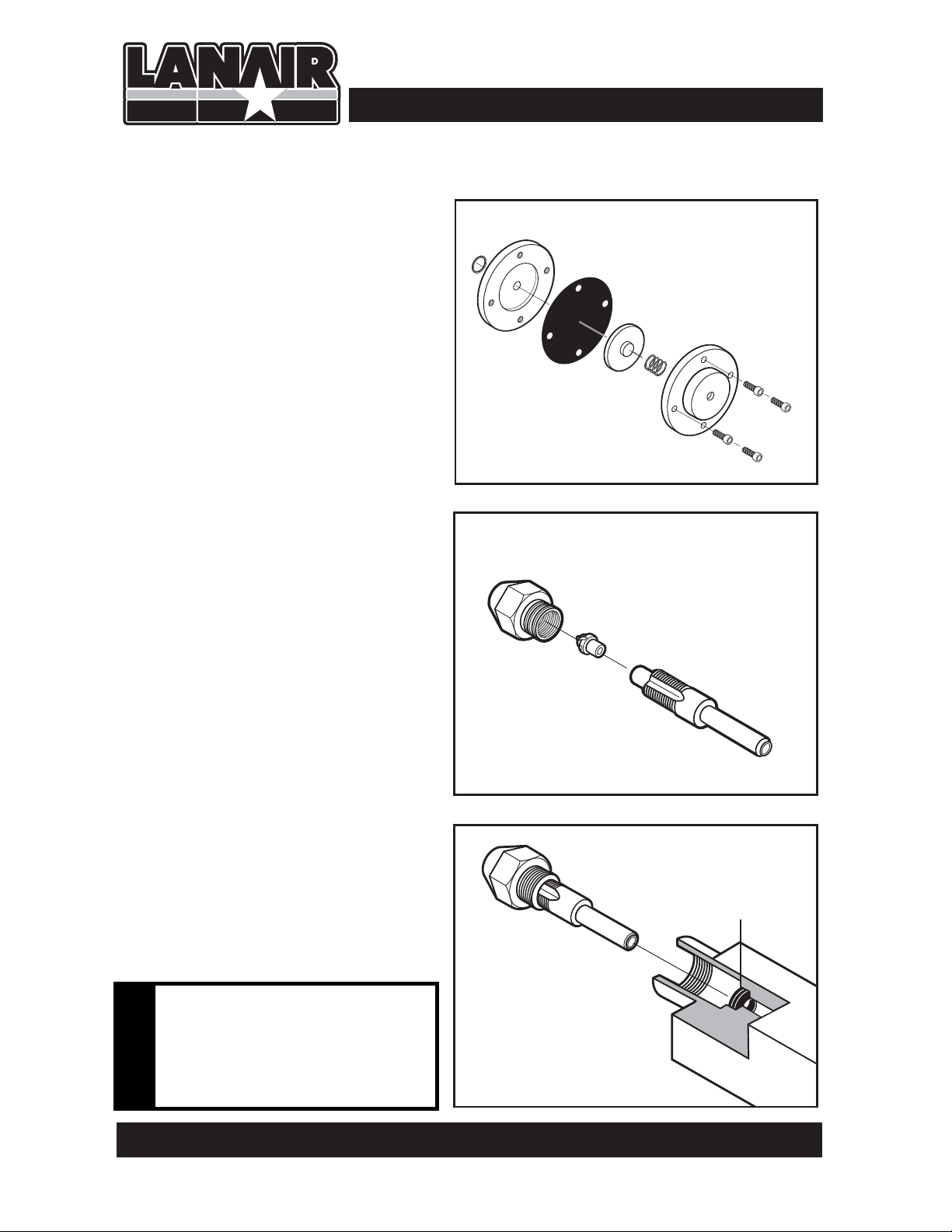
Air Pre-Heater Diaphragm Breakdown
1. Remove the four hex cap screws
from the diaphragm assembly
Section 13 - Service / Maintenance
o-ring
2. Disassemble and inspect diaphragm,
spring and o-ring .
3. Thoroughly clean remaining parts.
4. Re-assemble the diaphragm,
o-ring, spring and hex cap screws.
Air Pre-Heater Nozzle Cleaning /
Replacement
1. Periodic cleaning of the nozzle
assembly may be required.
2. Carefully remove nozzle from the air
pre-heater block.
3. Disassemble the nozzle as shown
and clean thoroughly.Re-assemble
nozzle.
4. Carefully remove the quad ring from
the block and inspect. Replace if necessary.
5. Insert clean/new quad ring into the
air pre-heater block. NOTE: The quad
ring must be properly seated.
Failure to properly seat the quad
ring may result in leakage and
improper burner operation. DO NOT
INSTALL QUAD RING ON THE NOZZLE.
6. Lubricate pin/seat
zle. Tighten gently.
and re-install noz-
diaphragm
piston
spring
Air Pre-Heater Diaphragm Assembly
body
fuel orifice
pin/seat
Air Pre-Heater Nozzle Assembly
nozzle assembly
hex cap
screws
quad ring
Failure to properly seat the quad
ring may result in leakage and
improper burner operation. DO
!
NOT INSTALL QUAD RING ON
THE NOZZLE.
QUESTIONS?... Contact Customer Service at 1-888-370-6531 M-F 8:00 am- 4:15 pm CST
Proper Quad Ring Position
40
Page 45

Section 13 - Service / Maintenance
NOTE: ALWAYS WEAR EYE,FACE AND BREATHING PROTECTION AND PROTECTIVE
CLOTHING WHEN INSPECTING OR CLEANING CHAMBER OR HEAT EXCHANGER.
!
WARNING: DISCONNECT ALL ELECTRICAL POWER TO HEATER BEFORE
SERVICING
!
Cleaning Combustion Chamber/ Heat Exchanger
1. Turn thermostat to the
lowest setting; the
heater must be completely cool to the
touch before attempting to clean the heater
(place the fan/limit on
the manual position to
start the fan and shorten the cooling time if
the unit is hot).
REMOVE
SCREWS
FAN LIMIT SWITCH
2. Turn off all power to
the heater (120 VAC) at
the main disconnect.
Place the fan/limit
switch lever back into
the auto position so
the fan is off upon
restarting.
3. Remove the burner
and flame view port
from the heater.
Remove the galvanized panel covering
the clean-out cover
(remove four (4) #10
screws from the top
and four (4) #10 screws
from the bottom of the
panel and remove).
Spray all of the screws with penetrating oil to prevent breakage before removing
4.
any of the nuts that secure the combustion chamber access door. Let set for
minutes to allow the oil to penetrate.
REMOVE
SCREWS
REMOVE 14 NUTS & WASHERS
five
5.
Remove the clean out cover from the heater by removing (14) 1/2 hex head nuts &
washers. If more than 1/4” of ash is present clean the heat exchanger tubes.
Visit our website at: www.lanair.com
41
Page 46

Section 13 - Service / Maintenance
CAUTION:THE CLEAN OUT PANEL MUST HAVE AN AIR TIGHT SEAL TO
PREVENT EXTREME DAMAGE TO THE COMBUSTION CHAMBER
!
CAUTION:TO AVOID BOLT BREAKAGE, DO NOT OVER-TIGHTEN
!
6. Use an industrial type canister vacuum cleaner with a high efficiency filter, or suitable
tool. Failure to clean heat exchanger tubes annually will impair draft. Reaching
through the burner opening, vacuum or shovel the ash from the combustion chamber.
Inspect the combustion chamber and target brick. Use care when cleaning the
combustion chamber area so the target brick is not disturbed. Insufficient or irregular
cleaning intervals will cause inefficiency, random shutdowns, and extreme damage to
the combustion chamber.
7. Before replacing the combustion chamber access doors, replace the white gasket seal on
the door (contact the Lanair Service Department).When replacing the gaskets apply a
light film of gasket adhesive to adhere the new gasket to the door.Lube the threads of
the screws with a high temperature lubricant. Re-install the heat exchanger access panel.
If any nuts are stripped, replace (use brass).
8. Replace the inspection port with the two (2) #8 hex head sheet metal screws (if
removed). Re-install the clean out cover. Replace burner.
9. Remove the clean out panel on the front left of unit by removing (4) #8 screws to
expose the manifold clean out port.
10. On the left side facing the front of the unit remove the (4) #10 sheet metal screws from
the manifold clean out port. Using an industrial type canister vacuum cleaner with a
high efficiency filter, remove all ash accumulation.
11. The chimney connector can also be removed to allow access to the mani
ing. Clean and inspect the chimney connector if necessary. Replace the four (4) #10
screws in the clean out ports on the heater. Replace the front clean out plate, replacing
the ten (4) #8 sheet metal screws. Check your draft reading to make sure your barometric damper is properly set (See Section 4).
12. Remove roof chimney cap and cleanout tee cap. Using a properly sized chimney brush
sweep ash and soot from roof downward until the chimney is completely clean.
Reinstall chimney and cleanout tee caps.
13. Reconnect all power at the main breaker box, wait ten minutes before turning the ther-
mostat up. Your heater is now ready for normal operation.
NOTE: When changing the target brick, call the Lanair Service Department for assistance.
fold for clean-
WARNING: DO NOT OPERATE YOUR FURNACE WITH CLEAN OUT PANELS
OR PORTS REMOVED
!
QUESTIONS?... Contact Customer Service at 1-888-370-6531 M-F 8:00 am- 4:15 pm CST
42
Page 47

Section 13 - Service / Maintenance
Fuel By-Pass Regulator Assembly
adjusting screw
locking nut
small plug
spring
cap
NOTE:
SKIP THIS SECTION WHEN USING
THE OPTIONAL METERING PUMP
Fuel By-Pass Regulator
Diaphragm Replacement
1.
Disconnect power to the heater.
2.
Remove the locking nut and adjusting
screw from the by-pass regulator
assembly.
3.
Disassemble the by-pass regulator and
discard the small plug, spring, large
plug. washer and diaphragm.
parts.
4.
Thoroughly clean and dry remaining
5.
Re-assemble using new small plug,
spring large plug washer and
diaphragm (Kit P/N 9874).
NOTE: Pay close attention to the positions of the large and small plugs.
large plug
washer
diaphragm
body
Visit our website at: www.lanair.com
43
Page 48

Section 14 - Troubleshooting
Initial Diagnosis:
When an operating problem occurs, a determination must be made whether or not the fuel
pump is pumping a sucient amount of oil that contains no air or water.
Take these steps:
tAdjust the burner air regulator to -0- PSI.
tTurn pre-heater rocker switch o (red light o ).
tShut o oil supply line valve to the burner.
tRemove the fuel supply line from the supply tank.
tWhen using a by-pass regulator attach a exible piece of tubing at least 3 feet long to the
outlet on the return side of the oil by-pass regulator.
tWhen using a metering pump disconnect the fuel supply line from the burner.
tInsert the tubing into the bottom of a large jar.
tJump the cad cell circuit and start the fuel pump (see below).
tAttempt to ll the jar above the open end of the tubing.
tIf the pump will not pump fuel, attempt to prime the pump (Section 10). If the pump
won’t prime refer to Flow Chart Item B.
If no air or water is present the ow must be determined:
tWhen using a by-pass regulator pump fuel for 1 minute into a graduated container, if the
ow rate is less the 250 MILS/Minute (8-1/2 Ounces), refer to Section 14 Troubleshooting
Chart Item B.
If the ow rate is more than 250 MILS/minute (8-1/2 Ounces), refer to Troubleshooting
Chart Item C.
When using the optional metering pump:
Pump fuel for 1 minute into a graduated container. The ow rate will vary by model.
MX-150 . . . . . . . . . . . . . . . . . . 66 ML/MIN
MX-200 & MXD-200 . . . . . . 87 ML/MIN
MX-250 & MXB-250 . . . . . . 109 ML/MIN
MX-300 & MXD-300 . . . . . . 139 ML/MIN
If ow rate using a metering pump is more than +/- 10% contact Lanair Service at
888-370-6531.
After repairs are made, remove the cad cell
jumper wire, and reconnect the cad cell wires
to the oil primary.
By-passing the oil primary safety circuit:
Some trouble-shooting test may require the cad
cell safety circuit in the oil primary control to be
bypassed, to do this:
t3FNPWFUIFZFMMPXXJSFTGSPNUIF''
terminals on the oil primary control.
Remove two yellow wires
WARNING: DO NOT OPERATE YOUR HEATER IF THE OIL PRIMARY
SAFETY CIRCUIT IS NOT WORKING!
!
QUESTIONS?... Contact Customer Service at 1-888-370-6531 M-F 8:00 am- 4:15 pm CST
44
Page 49
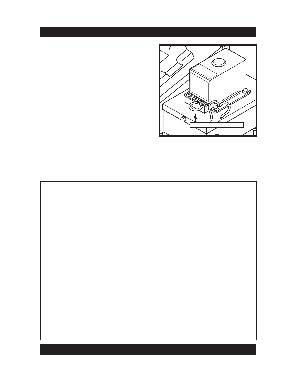
s Install a jumper wire between the two F-F
terminals. Be careful not to touch the T-T
terminals as it may damage the control.
s Push reset button for 2 seconds.
s Turn room thermostat up so that it calls for
heat.
s Disable the air operated fuel valve.
s To activate the oil primary momentarily dis
connect one end of the jumper wire on the
F-F terminals.The burner will attempt to fire.
Section 14 - Troubleshooting
IMPORTANT remove the jumper wire when
testing is complete, and replace the cad cell
wires. Do not run the heater with the cad cell
wires disconnected.
Install jumper wire
Disabling the air operated fuel valve.
Note: Most trouble shooting tests will require the air operated fuel valve to be disabled, to
do this:
s Adjust the heater air filter/regulator to -0- PSI.
Vacuum Gauge reading hints:
No reading 0-1 HG
s Pump not operating.
s Pump air locked and needs priming. Refer to section 10.
s Vacuum leak: ✓ Pump shaft seal ✓ Pump cover gasket
✓ Suction strainer gaskets ✓ Low fuel level in tank
✓ Pipe connections suction side ✓ Strainer in pump cover
Low to normal reading,1-6 inches HG.
s Pump operating properly. s Fuel being used has a low viscosity.
s Fuel oil is being used. s Fuel is at room temperature (warm).
s High level of gasoline in the fuel (use approved fuels only).
High reading, 7 inches of HG, or more.
s Fuel being used has to high of a viscosity. s Suction line strainer dirty or plugged.
s Fuel contains gear lubes (use approved fuels only).
Reading fluctuates (jumps).
s Vacuum leaks in the suction side of the piping to the pump.
s Low fuel level in the tank.
Visit our website at: www.lanair.com
45
.kcuts ro gnorw dellatsni evlav kcehC s.dloc oot si leuFs
Page 50

Section 14 - Troubleshooting
Burner fuel pressure gauge reading hints:
Fuel gauge fluctuates (jumps):
s Leak in suction line plumbing.
s Water/Anti-freeze in fuel.
s Air in fuel, refer to Troubleshooting Chart Item B.
s Quad ring seal for the nozzle may be damaged.
s Seal in adapter block may be worn or damaged.
s Fuel pressure regulator seal leaking or dirty when using a by-pass regulator.
s Suction line strainer plugged or dirty.
Reading gradually decreases:
s Fuel pump output decreasing.
s Fuel viscosity decreasing.
s Orifice in nozzle is wearing.
Reading gradually increases:
s Fuel pump output increasing.
s Fuel viscosity increasing (cold fuel, and/or gear lube).
s Orifice in nozzle is becoming plugged.
Reading drops to –0- PSI when the burner is off.
s Dirt between the diaphragm and the seat in the by-pass regulator when using a
by-pass regulator.
s Dirt between the plunger and the nozzle seat.
s Leak in the plumbing connections.
s Leak in
s Fuel pre-heater switch is off.
the pre-heater assembly (damaged or missing o ring).
Steps to check the air operated fuel valve:
s
Disconnect the two transformer wires from the terminal block in the burner.
s Jump the cad cell circuit (refer to pages 44-45).
s Disconnect the fuel supply pump orange wire from the terminal block inside the
burner.
s Set the dial indicator as shown on the diaphragm piston.
s Zero the dial indicator.
s Start the burner so that the air valve opens.
NOTE: The dial indicator should read +.015 to .050,which references the diaphragm
piston travel.
QUESTIONS?... Contact Customer Service at 1-888-370-6531 M-F 8:00 am- 4:15 pm CST
46
Page 51

Section 14 - Troubleshooting
Symptom Possible Cause Corrective Action
A. Burner will not start 1. Main electrical power 1. Reset breaker
circuit breaker tripped
2. Service disconnect 2. Turn switch on or
switch off or fuse blown replace fuse
3. Thermostat turned down/ 3. Turn thermostat up,
improperly installed/ check wires/test
defective components/replace
4. Oil primary safety 4. Reset/test components,
tripped/defective replace if needed
5. Too much light showing 5. Eliminate light to cad cell
on cad cell/defective Test component
B. Burner attempts to fire, 1. Low oil in supply tank or 1. Fill tank, or drain and
but does not establish a contaminated fuel clean tank
flame
2. Plugged or worn nozzle 2. Clean or replace
3. Fuel pressure gauge 3. See section 6, Page 17
fluctuating/pumping system
4. Pre-heater switch is turned off 4. Turn switch on or test
or defective, or defective switch and cartridge heater
cartridge heater
5. Transformer/electrodes not 5. Test transformer/look
sparking for shorts & repair
Replace electrodes/
transformer
6. No air pressure/defective 6. Turn compressor on/test
regulator/defective solenoid regulator/solenoid. Replace
defective components
7. Water in air system 7. Clean air pre-heater and
drain water from system
8. Combustion blower not 8. See flame adjustment
properly adjusted or pages 29-31.
defective Replace blower
9. Improper draft 9. Check draft see page 15.
Make sure chimney is
properly installed
10. Plugged heat exchanger, 10. Clean heater including
or chimney manifold, chimney
Visit our website at: www.lanair.com
47
Page 52

Section 14 - Troubleshooting
noitcA evitcerroCesuaC elbissoP motpmyS
C. Burner fires, and then 1. Contaminated fuel supply 1. Drain and clean fuel
fails on oil primary safety (water/anti-freeze/gear lube) supply tank. Clean fuel
or dirty fuel filter. filter (see page 38)
2. Improper draft 2. Check draft see page 15.
Make sure chimney is
properly installed
3. Plugged heat exchanger, 3. Clean heater including
manifold, or chimney manifold and chimney
4. Wrong air pressure 4. See flame adjustment pages
29-31
5. Wrong fuel pressure or 5. See flame adjustment
pressure fluctuating pages 29-31. See fuel piping
page 17
6. Improper combustion blower 6. See flame adjustment
setting, or blower is defective pages 29-31. See fuel piping
page 17
7. Oil primary/cad cell defective. 7. Test components/adjust
Cad cell improperly adjusted. cad cell/ clean turbulator
Dirty flame turbulator.
8. Plugged nozzle or pre-heater 8. Clean nozzle and /or
pylbmessa
D. Pre-heater assembly 1. Cartridge heaters defective 1. Test cartridge heaters
not heating or disconnected using an ohm meter.
Air heater 112 Ω ±10%.
Oil heater 37 Ω ±10%.
Snap disc defective 2. Test snap switch for
continuity if
pre-heater is cold
ylbmessa retaeh-er
QUESTIONS?... Contact Customer Service at 1-888-370-6531 M-F 8:00 am- 4:15 pm CST
48
Page 53

Return Guidelines and Warranty
Return Guidelines
1. All returned merchandise must be unused and returned in the same new condition in
which it was originally received, with all accompanying original packaging. Any items
returned used, damaged in any way or with missing components will not be refunded.
Return merchandise must be shipped freight prepaid.
2. All returns must be authorized by the Lanair Customer Service Department.
Unauthorized returns will NOT be accepted or refunded, and may be refused when
received.
3. Authorized returns for merchandise in original boxes and in new condition are subject
to a 20% restocking charge. No returns are accepted on custom or special order items.
Electrical components maybe subject to inspection.
4. All returns must be made within fifteen (15) days after the date of the shipment for
orders within the United States. For foreign orders, the return must be made within
sixty (60) days of the initial shipment.
5. All authorized returns will be fully refunded less restocking fees, shipping and handling
charges.
6. To obtain an authorization number, please call our customer service department at
1-888-370-6531, or email us at service@lanair.com
7. All authorized returns must have the authorization number marked on the outside
of the package and returned to the following address:
Lanair Products LLC
Returns Department
4109 Capital Circle Drive
Janesville, WI 53546
Warranty Conditions
Lanair Products LLC (Manufacturer) warrants to the original purchaser of this used oil
heater, that it will repair or replace at Lanair Products LLC’s option, any part which is in
normal use proves to be defective in material or workmanship within a period of one
year from the date of purchase, provided same is returned (transportation pre-paid)
F.O.B. Janesville Wisconsin, for Lanair Products LLC’s inspection and warranty
determination. Normal wear and tear items are not covered. Lanair Products does not
warrant paint finish. The warranty does not cover labor charges involved with part
replacement or service unless pre-authorized in writing. Lanair Products LLC may also
require photographs of the heater installation for warranty determination.
QUESTIONS?... Contact Customer Service at 1-888-370-6531 M-F 8:00 am- 4:15 pm CST
49
Page 54

Section 15 - Warranty
LANAIR 10 YEAR WASTE OIL HEATER COMBUSTION
CHAMBER AND HEAT EXCHANGER LIMITED WARRANTY
Lanair Products LLC, MANUFACTURER, hereby warrants that any part of manufacturer’s product shall be free from
defect in material and workmanship under normal use according to the provisions and limitations herein set forth for a
period of one (1) year provided same is returned (pre-paid) F.O.B. Janesville, Wisc. for inspection and warranty
determination.
MANUFACTURER warrants the heat exchanger/combustion chamber for three (3) years from the date of purchase and
pro rata thereafter according to the following schedule: If a defect occurs during the first three years,
MANUFACTURER will repair or replace the combustion chamber/heat exchanger FREE* of charge. If a defect occurs
in years four through ten (4-10) MANUFACTURER will repair or replace your combustion chamber/heat exchanger.
Your guaranteed replacement cost will be shared by MANUFACTURER 50/50.
IMPORTANT: Combustion chamber / heat exchanger must be maintained in accordance with the
installation / operating instructions. This extended warranty does not cover normal wear items such as gasket material,
chamber inserts, nuts, bolts, labor costs, etc. The warranty card must be returned within ten (10) days of purchase date
in order for this warranty to be valid. Warranty is limited to original purchaser.
*MANUFACTURER’S determination regarding repair or replacement is final.
Cost of freight is owner’s responsibility.
:desahcruP etaDModel Number: MX Series Heater
Conditions That Will Void Warranty
s Use of liquids such as: solvents, brake fluid, gasoline, K-1, kerosene, paint thinners, gear lube,trans-
former oil, cutting oils, anti-freeze, water or any other liquid not approved for use.
s Tampering with internal components
s Failure to inspect and clean combustion chamber/heat exchanger at the end of each heating season.
s Continuous over-firing of the unit
s Heater has not been installed or serviced in accordance to the installation / operating manual.
s Alteration or misuse of any part
s Use of parts other than those supplied by Lanair.
NOTE: Lanair may require photographs of the heater installation for warranty determination
NOTE: Re-stocking fee of 20% applies on all returned parts
Items Not Covered Under Warranty
s Any portion of the combustion chamber / heat exchanger if:
- The unit is not installed per the owners manual.
- The yearly inspection requirements are not current.
- If the heater is used for a purpose for which it is not intended.
- If the heater is not operated in accordance with the printed instructions in the
- If any alterations or unauthorized repairs are made to the unit.
s Damage incurred from abuse, neglect, shipping, natural acts, misuse or accident.
s Labor costs for service calls for any reason including:
- Cleaning or performing required maintenance.
- Installation corrections
- Any parts installation.
s Parts that are replaced because of normal wear and tear.
s Goods purchased under this agreement shall be used exclusively by the buyer and
other person or third party shall benefit from the express or implied warranties contained
in the agreement.
no
QUESTIONS?... Contact Customer Service at 1-888-370-6531 M-F 8:00 am- 4:15 pm CST
50
Page 55

Section 16 - Burner Reference Diagram
Ignitor
Fuel Supply
Pre-Heater
Adjustment
Oil Pressure
Gauge
Screw
Oil
Pre-Heater
Block
Pre-Heater
View Port
Air
Block
Manual
Reset &
Snap Disk
Air
Supply
To Combustion
Blower
Air
Solenoid
Pre-Heater
Switch
Air Supply
Electrical Quick
Disconnect
To Transformer
Cad Cell
Burner Cover
Visit our website at: www.lanair.com
51
To “F”
Terminals
To Oil Primary
Page 56

Lanair Products LLC
4109 Capital Circle
Janesville, Wisconsin 53546
1-888-370-6531
www.lanair.com
®
© 2009 Lanair Products LLC
Lanair is a registered trademark of Lanair Products LLC
Part # 5032
REV .21a
11-16-10
 Loading...