

Page 1

pH/TDS/Salt
TRACER
POCKETESTER
TM
CODE 1766
pH/Conductivity/TDS/Salinity Meter
Page 2

WARNING! This set contains chemicals
that may be harmful if misused. Read
cautions on individual containers
carefully. Not to be used by children
except under adult supervision
Page 3

TRACER
pH/TDS/SALT POCKETESTERTM• CODE 1766
TABLE OF CONTENTS
Introduction .............................. 4
Specifications ............................. 5
Contents ............................... 6
Parts & Accessories .......................... 6
Meter Description
Front Panel Description ......................... 7
TRACER Display ............................ 7
Basic Operation
Powering the TRACER ......................... 8
Electrode Recognition .......................... 8
Automatic Calibration ......................... 8
TDS Conversion Ratio .......................... 8
Changing the Displayed Temperature Units ............... 9
Data Hold ................................. 9
Auto-Power Off .............................. 9
Low Battery Indicator........................... 9
Testing
Getting Started ............................. 10
Changing the Measurement Function.................. 10
Measurement .............................. 11
Measuring the TDS of Soil ....................... 12
Storing Readings............................. 13
Recalling Stored Readings........................ 13
Clearing the Memory .......................... 13
Calibration
pH.................................. 14-15
Conductivity ............................. 15-16
Operational Matrix ........................ 17-18
Maintenance
Storage ................................. 19
Battery Replacement .......................... 19
Electrode Care .............................. 19
Replacing the Electrode ........................ 20
Electrode Cleaning Recommendations ................. 20
Troubleshooting ........................... 21
Warranty ............................... 22
3
Page 4

INTRODUCTION
Congratulations on your purchase of the pH/TDS/SALT
(pH/conductivity/TDS/Salinity) TRACER PockeTester. The TRACER
is a revolutionary, first of its kind measurement device that offers direct
reading of pH, conductivity, TDS and salinity with one electrode.
Careful use and maintenance will provide years of reliable service.
4
Page 5

SPECIFICATIONS
Display 2000 count LCD with Bar Graph
pH Range 0.00 to 14.00
pH Accuracy ± 0.01 pH typical
pH ATC Range 32 to 194 °F (0 to 90 °C)
pH Measurement Storage 25 tagged (numbered) readings
pH Reference Junction Permanent gel, non-refillable
Conductivity Range 0 to 199.9 µS/cm
200 to 1999 µS/cm
2.00 to 19.99 µS/cm
TDS Range 0 to 99.9 ppm and mg/L
100 to 999 ppm and mg/L
1.00 to 9.99 ppt and g/L
(variable ratio)
Salinity Range 0 to 99.9 ppm S
100 to 999 ppm S
1.00 to 9.99 ppt S
(fixed ratio of 0.5)
TDS Ratio 0.4 to 1.0, adjustable
Salinity Ratio 0.5 fixed
Conductivity ATC 2.0% per °C
Conductivity ATC Range 32.0 to 140.0 °F (0.0 to 60.0 °C)
Temperature Range 23.0°F to 194°F (–5.0°C to 90.0°C)
Temperature Resolution 0.1 up to 99.9, 1 >100
Temperature Accuracy ±1.8°F; 1°C; (from 23 to 122°F; -5 to 50°C)
±5.4°F; 3°C; (from 122 to 194°F; 50 to
90°C)
Conductivity ATC Range 32.0°F to 140°F (0.0°C to 60.0°C)
Accuracy Conductivity: ±2% FS
TDS: ±2% FS
Salinity: ±2% FS
Measurement Storage 25 numbered readings
Low Battery Indication ‘BAT’ appears on the LCD
Power Four CR2032 Lithium Ion batteries
Auto Power Off After 10 minutes of no button presses
(override available)
5
Page 6

Operating Conditions 23 to 122 °F (–5 to 50 °C)
Dimensions 1.6 X 7.9 X 1.6 inches, 40 X 200 X 40 mm
Weight 3.3 oz, 93 g
NOTE: 1 part per thousand (ppt) equals 1000 parts per million (ppm).
Example: 3.1ppt=3,100 ppm
CONTENTS
pH/CON TRACER PockeTester Kit Code 1766
Includes:
Sample Cup w/cap *
Tablet Crusher Code 0175
Buffer Tablets, pH 4.0, 7.0 & 10.0 *
*Not sold in this quantity. See below.
PARTS & ACCESSORIES
pH/TDS/SALT Replacement Electrode Code 1755
Weighted Stand w/Sample Cups (5) Code 1746
Sample Cups w/caps (24) Code 1745
pH 4.0 Mini Buffer Tablets (100) Code 3983A-J
pH 7.0 Mini Buffer Tablets (100) Code 3984A-J
pH 10.0 Mini Buffer Tablets (100) Code 3985A-J
Conductivity Standard, 84 µS, 30 mL, 500 mL Code 6312-G, L
Conductivity Standard, 1413 µS, 30 mL, 500 mL Code 6354-G, L
Conductivity Standard, 12,880 µS, 30 mL, 500 mL Code 6317-G, L
6
Page 7
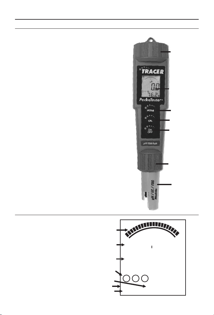
METER DESCRIPTION
Front Panel Description
1. Battery compartment cap
2. LCD Display
3. MODE/HOLD button -
change mode, hold data, store data
4. CAL/RECALL button - calibration,
change temperature units,
recall data
5. ON/OFF button
6. Electrode Collar
7. Electrode
(Note: The Electrode cap is not shown)
1
2
3
4
5
6
7
TRACER Display
1. Bar graph display
2. Measurement units
3. Main display
4. Range calibration and
battery indicators
5. Temperature display
6. Renew indicator
7. HOLD indicator
1
0
t
pp
0
2
3
4
5
6
7
m
2
88.88
M HL
RENEW
HOLD
7
5
10
7
m
mg/L
S
u
pH %
BAT
-8.8.8
10
20
12
°C
°F
Page 8

BASIC OPERATION
Powering the TRACER
The Tracer uses four CR 2032 Lithium Ion batteries. If the batteries are
weak, the BAT indicator will appear on the display. Press the ON/OFF
button to turn the TRACER on or off. The auto power off feature will
shut the TRACER off automatically after 10 minutes after the last
button push.
Automatic Calibration
When the TRACER is turned on, it will enter the Automatic
Calibration mode. SELF and CAL will appear while the calibration is in
progress. After the calibration is completed, the SELF and CAL display
icons will extinguish.
TDS Conversion Ratio
The TDS value is determined by multiplying the conductivity
measurement by a known conversion ratio factor. The meter allows the
selection of a conversion ratio factor in the range of 0.4 to 1.0. The
selected ratio will vary with application but is typically set between 0.5
and 0.7. In the salinity mode, the ratio is fixed at 0.5. The stored ratio
factor will briefly appear in the lower temperature display when the
meter is first turned on or when changing the measurement function to
TDS.
To change the ratio while in the TDS measurement mode:
1. Turn the TRACER on.
2. Press and release the CAL/RECALL
button twice. The stored ratio will
appear in the display.
3. Press the MODE/HOLD button to change
the ratio value in steps of 0.1.
4. When the desired ratio is displayed, press
and release the CAL/RECALL button
to store the value and return to the
normal mode.
5. If no buttons are pressed for 5 seconds, the meter will return to the
measurement mode.
8
Page 9

Changing the Displayed Temperature Units
To change the displayed temperature units between °C or °F:
1. With the TRACER off, press and hold the CAL/RECALL button.
2. With the CAL/RECALL button pressed, momentarily press the
ON/OFF button. When SELF CAL appears in the display, release
the CAL/RECALL button. The TRACER will return to the
operational mode with the temperature displayed in the new units.
Data Hold
Press the MODE/HOLD button to freeze the current reading. The
HOLD icon will appear. The reading will be stored. Press the
MODE/HOLD key to return to normal operation.
Auto-Power Off
The auto-power off feature will automatically shut the meter off 10
minutes after the last button was pressed. To disable the auto-off feature:
1. Press the ON/OFF button to turn the meter on.
2. Wait for the SELF display screen to appear. This is the second
screen to appear after turning on the meter. IMPORTANT: Review
the instructions for the next 3 steps before proceeding. Step 3 must
be followed immediately by Step 4.
3. Press CAL/RECALL button once.
4. Press MODE/HOLD and ON/OFF buttons simultaneously, for
approximately 2 seconds.
5. oFF will be displayed on the screen. Watch carefully. It will
disappear quickly.
6. To re-enable the auto-off feature, repeat steps 3 and 4. ON will be
briefly displayed on the screen.
7. The auto power off feature will be restored automatically when the
meter is turned off. Auto-off is the default function when the meter
is turned on.
Low Battery Indicator
The “BAT” indicator will be displayed when the batteries become weak.
Refer to the Maintenance section for battery replacement information.
9
Page 10

TESTING
Getting Started
1. Remove the cap from the bottom of the TRACER to expose the pH
electrode, reference junction and the conductivity electrodes.
2. Before the first use or after storage, soak the electrode in tap water or
pH 4 buffer for 10 minutes.
3. White KCL crystals may be present in the cap or on the electrode.
This is to be expected if the TRACER has been stored for any
length of time. The crystals will dissolve with soaking or they can be
rinsed off with tap water.
4. Calibrate with pH 7 buffer prior to the first use or after prolonged
storage.
5. When the meter is calibrated for conductivity, salinity or TDS the
meter must be in the conductivity mode. See page 15.
Changing the Measurement Function
The meter can be set to measure Conductivity, pH, Salinity (ppm),
TDS(ppm), or TDS (mg/L). To change the mode:
1. Turn the TRACER on.
2. Press and hold the MODE/HOLD button for 2 seconds. The display
will begin to scroll through the units.
µS or mS (Conductivity)
pH
ppm S or ppt S (Salinity)
ppm or ppt (TDS)
mg/L (TDS)
NOTE: 1 part per thousand (ppt) equals 1000 parts per million (ppm).
Example: 3.1ppt=3,100 ppm
3. Release the MODE/HOLD key when the desired mode is displayed.
NOTE: The “HOLD” function can not be used when changing the
measurement function. If “HOLD” is displayed in the lower left corner
of the display, briefly press the MODE/HOLD button to turn it off.
10
Page 11

MEASUREMENT PROCEDURE
Measurement
1. For small samples fill a sample cup to the 20 mL line with the test
sample. Sample depth must be greater
than or equal to 1.5 inches. pH can also
be measured by contact of the electrode
tip with a wet surface. For larger samples,
pH
Conductivity
TDS Salinity
pH
like pools, go to step 2
2. Press the ON/OFF button. (8888 and
then SELF CAL will appear in the display
during the initial diagnostics).
Pools and
Wate r
Surfaces
Only
3. Press and hold the MODE/HOLD button
to scroll to the desired measurement
mode.
4. Immerse the TRACER electrode in the sample.
Make sure the electrode is completly submersed.
5. Slowly stir the sample with the TRACER to
remove air bubbles if in the Conductivity,
TDS or Salinity mode.
6. If the TRACER is in the Conductivity, TDS,
or Salinity mode, the meter will automatically
auto-range to the proper range and then display
MODE
CAL
ON
OFF
pH/TDS/Salt
the reading.The display will flash “0000” while
autoranging.
7. If the TRACER is in the pH mode, the reading
will flash until it has stabilized. This may take
several seconds depending on the buffer capacity
of the sample.
8. Rinse the electrode in distilled water. Replace
the cap.
NOTE: 1 part per thousand (ppt) equals 1000 parts per million (ppm).
Example: 3.1ppt=3,100 ppm
11
Page 12

NOTE: When measuring samples with low conductivity, thoroughly
rinse the probe with distilled or deionized water before placing it in the
sample to avoid contamination of the sample with electrolyte from the
pH reference electrode. Also increase the sample size to 200 to 500 mL
to decrease the chance of contamination. If a sample cup is used, do not
allow the probe to sit in the sample for any longer than necessary to
avoid electrolyte leakage into the sample. Leakage will raise the
conductivity level.
Measuring the TDS of Soil
1. Fill a 50 mL beaker with the soil sample. Tap the beaker lightly on a
hard surface to remove trapped air. Remove excess soil from the
surface.
2. Empty the soil into a 250 mL wide-mouth flask.
3. Add 100 mL of distilled water. Stopper and shake vigorously.
4. Wait 30 minute. (Shake the flask vigorously three or four times
during this period.)
5. Filter the contents of the flask. Collect the filtrate in a beaker.
6. Rinse the electrode with distilled or deionized water to remove
impurities.
7. Press the ON/OFF button to turn the TRACER on. Make sure the
meter is in the TDS mode.
8. Immerse the electrode in the filtrate. Make sure the tip of the
electrode is completely immersed.
9. Stir the filtrate with the electrode to create a homogeneous solution.
10. Gently stir the filtrate with the electrode. Read the TDS value of
the filtrate from the display.
11. Rinse the electrode in distilled water. Replace the cap.
12
Page 13

Storing Readings
1. After the reading is displayed press and hold the MODE/HOLD
button to store the current reading. The
meter will enter the HOLD mode and HOLD
will be displayed. The storage location
number (1 through 25) will be displayed on
the lower display followed by the reading
being stored.
2. Press the MODE/HOLD button to exit the
HOLD mode and return to normal operation.
3. If an attempt is made to store more than 25
readings, the stored readings will be
overwritten starting with the first reading.
Recalling Stored Readings
NOTE: First ensure that the HOLD symbol is not displayed. If it is, exit
the HOLD function by pressing the MODE/HOLD button.
1. Press the CAL/RECALL button and then press the MODE/HOLD
button. The location number (1 through 25) will briefly appear and
then the value stored in that location will appear. The displayed
units will flash, indicating that the storage recall mode is active.
2. The last stored reading taken will be displayed first. To advance to
the previously stored readings, press the MODE/HOLD button. The
location number is displayed first, followed by the reading stored in
that location.
3. To exit the storage mode, press the CAL/RECALL button and the
TRACER will return to normal operation after displaying “End”.
Clearing Stored Memory
Turn the TRACER on. Press and hold the ON/OFF button for 4
seconds. The display will briefly display “clr” when the memory is
cleared.
1313
Page 14

CALIBRATION
For the most accurate results, allow sufficient time for the temperature
of the probe to reach the temperature of the sample before calibrating.
This will be indicated by a stable temperature reading on the display.
pH
The TRACER can be calibrated at 1, 2 or 3 points. For the most
accurate results with a two point calibration, calibrate the TRACER
with a pH 7 buffer first, then calibrate with either a pH 4 or pH 10
buffer whichever is closest to the pH value of the sample to be tested.
When performing a three point calibration, calibrate with the pH 7
buffer first, followed with the pH 4 buffer and then the pH 10 buffer.
Preparation of Buffers
1. Fill a sample cup with 20 mL of distilled or deionized water.
2. Add one buffer tablet:
pH 4.0 Code 3983A
pH 7.0 Code 3984A
pH 10.0 Code 3985A
3. Use the tablet crusher (0175) to crush the tablet. Stir until the
tablet has disintegrated.
NOTE: Buffers should be prepared fresh daily.
Calibration
1. Fill a sample cup to the 20 mL line with a buffer solution.
2. Press the ON/OFF button to turn the TRACER ON.
3. Place the electrode in the buffer solution. Press and hold the
CAL/RECALL button until “CAL” appears in the lower display.
The meter will automatically recognize the buffer and calibrate itself
to that value. The circled number on the display will match the
value of the buffer.
NOTE: If the buffer solution is more than 1 pH unit off from 4, 7,
or 10, or the electrode slope is low,the meter will assume that there
is an error and the calibration will be terminated. END will be
displayed.
4. During the calibration the pH value on the display will flash. When
the calibration is complete, the TRACER will display “SA” and
“End” and return to normal operation.
5. The appropriately circled indicator (L, M or H) will appear on the
display when a calibration has been completed within one power on
cycle.
14
Page 15

6. For a two or three point calibration, repeat steps1–5with the
remaining buffers.
7. When the TRACER is turned off, the circled indicator
configuration and the calibration data will be memorized.
Calibration Reminder
The “CAL” indicator will appear when the TRACER is in the pH mode
and a calibration is required. The “CAL” indicator will appear if the
meter has not been calibrated after 15 on/off cycles of the meter. Some
applications may require more frequent calibrations than others. The
“CAL” indicator is only a reminder and will not affect function in any
way. The indicator will no longer be displayed when the pH electrode is
recalibrated.
RENEW Indicator
A flashing “RENEW” indicator will appear on the display to warn that
the electrode is not performing to expected specifications. If cleaning or
recalibration does not cause the RENEW indicator to disappear, the
electrode should be replaced. The RENEW indicator will appear when
the pH electrode slope falls below 70% of a nominal slope.
Conductivity
Meter accuracy verification should be performed on a periodic basis as
needed. If calibration is required, the meter must be in the
conductivity mode to perform all calibrations for conductivity, TDS
and salinity. The meter can perform a calibrations and store the data for
each of the three ranges – low, medium and high. The automatic
calibration recognition procedure will recognize conductivity standards
of 84µS (Low), 1413µS (Medium) or 12,880µS (12.88mS) (High). (See
Page 6). Always calibrate in the range closest to the expected
measurement value. For salinity samples within the range of 1.00 to
9.99 ppt salinity, calibrate with a 12,880µS calibration standard.
1. Fill a sample cup to 20 mL line with a conductivity standard.
NOTE: The meter allows for a 1, 2, or 3 point calibration. If
calibration is done for more than one point, the lowest
concentration should be done first to obtain the best accuracy.
Calibrate the ranges from low to high
2. Press the ON/OFF button to turn the TRACER on. Insert the
electrode into the standard. Tap or stir the sample with the Tracer
to dislodge air bubbles.
3. Press and hold the CAL/RECALL button for approximately 2
seconds until the display begins to flash.
15
Page 16

4. The meter will automatically recognize and calibrate to the
conductivity standard. The display will briefly indicate “SA” and
“End” and then return to the measurement mode.
NOTE: “SA” will not appear if the calibration fails.
5. The calibration range indicator will appear on the display for each
range that is calibrated during a power on cycle.
Low Range, 84 µS/cm
L
Medium Range, 1413 µS/cm
M
High Range, 12.88 mS/cm (12,880 µS/cm)
H
NOTE: Each time the calibration mode is entered all calibration
range indicators will be cleared, but only the calibration data for the
currently selected range will be replaced. The calibrations for the
other two ranges will be saved even though the indicators for those
ranges are no longer displayed. Calibration of all three ranges must
be performed during one power on period for all three calibration
range indicators to be displayed.
NOTE: As with all combination pH/conductivity probes, at low
conductivity levels the flow of the pH electrolyte may affect the
readings and result in artificially high conductivity readings. To
eliminate the interference, low level conductivity or TDS
measurements should be taken with a meter that measures
conductivity only.
16
Page 17

OPERATIONAL MATRIX
Function/
Resulting Action Power Mode
On/Off On or
Calibration On pH or
Store Reading On Any Momentary press of
Hold Release On Hold Momentary press of
Enter Memory
Retrieval
Scroll Stored
Readings
Exit Memory
Retrieval
Clear Stored
Memory
Off
On Any
On Memory
On Memory
On Any
Any Momentary press of
Con
Measurement
Mode
Recall
Recall
Memory
Mode
Key Press
Sequence
ON/OFF button
Press & hold
CAL/RECALL button
for 2 seconds until
CAL is displayed
MODE/HOLD button
MODE/HOLD button
Momentary press of
CAL/RECALL button
followed by a
momentary press of
MODE/HOLD button
within 4 seconds.
Momentary press of
MODE/HOLD button.
Displays last in first out.
Momentary press of
CAL/RECALL button
Press and hold the
ON/OFF button for
4 seconds until “clr” is
displayed.
17
Page 18

Function/
Resulting Action Power Mode
Change
Measurement
Mode
Enter CON/TDS
Ratio
Change
CON/TDS
Ratio
Exit
CON/TDS
Ratio
Change
TemperatureUnits
Override Auto
Power Off
Default Reset Off N/A Simultaneously press
On Any Press and hold the
On TDS
(ppm or
mg/L)
On TDS
(ppm or
mg/L)
On TDS
(ppm or
mg/L)
Off Off Press and hold
On Any
Measurement
Mode
Key Press
Sequence
MODE/HOLD button
for at least 2 seconds
Modes will scroll by
until button is released
Press and release the
CAL/RECALL button
twice in succession
Momentary press of
MODE/HOLD button.
Each press increases
ratio by 0.1 from 0.4 to
1.0.
Momentary press of
CAL/RECALL button.
CAL/RECALL button
then momentarily press
ON/OFF button.
Release CAL/RECALL
button after“Self Cal” is
displayed.
Momentarily press
CAL/RECALL button
then simultaneously
press and hold ON/OFF
and MODE/HOLD
buttons for 2 seconds
until “oFF” is displayed.
ON/OFF,
CAL/RECALL and
MODE/HOLD buttons
momentarily. “dFlt”
will be displayed.
18
Page 19

MAINTENANCE
Storage
1. Rinse the electrode in distilled or deionized water.
2. Store the electrode with the cap on. Keep the sponge in the cap
soaked with tap water or pH 4 buffer solution.
3. Always rinse the electrode in deionized water between
measurements to avoid cross contamination. Double rinsing is
recommended when high accuracy is required.
4. Salt deposits may build up in the storage cap and should periodically
be rinsed away. These deposits could affect measurements at low
conductivity.
Battery Replacement
1. Twist off the battery compartment cap.
2. Hold the battery housing in place with one finger. Remove the
battery carrier by pulling on the small tabs.
3. Replace the four CR2032 batteries. Observe polarity.
4. Replace the battery compartment cap.
Electrode Care
1. Always rinse the electrode in distilled or deionized water between
measurements to avoid cross-contamination of the samples. Double
rinsing is recommended when high accuracy is required.
2. Do not touch the electrodes. Touching the surface of the platinized
electrodes may damage and reduce the life of the electrodes.
19
Page 20

REPLACING THE ELECTRODE
1. Unscrew and remove the electrode collar. Turn collar
counter-clockwise.
2. Gently rock the electrode side to side, while pulling it away from the
meter, until it disconnects from the electrode socket.
3. To attach an electrode, align the slots and carefully plug the
electrode into the meter socket.
4. Firmly tighten the electrode collar to create a seal with the rubber
gasket between the electrode and the meter.
Electrode Cleaning Recommendations
Do not soak the electrode in the solutions for longer than the
recommended length of time. To do so may cause a reference potential
shift which will cause a degradation in performance or failure. When
cleaning the electrode, take care not to scratch or damage the sensing
surface or the platinized electrode surfaces.
Contaminant Cleaning Solution Procedure
Water soluble Deionized water Soak or scrub with a soft brush.
Grease and
oil
Heavy grease Alcohol Soak for a maximum of
Lime and
hydroxide
coatings
Warm water and
household detergant
10% Acetic acid Soak until coating dissolves,
Recondition in pH 4 or 7 buffer
for 1 hour.
Soak or scrub with a soft brush,
maximun 10 minutes. Rinse
thoroughly with DI water.
Recondition in pH 4 or 7 buffer
for 1 hour.
5minutes. Scrub with a soft
brush. Rinse thoroughly with
DI water. Recondition in pH 4
or 7 buffer for 1 hour.
maximum 5 minutes. Rinse
thoroughly with DI water.
Recondition in pH 4 or 7 buffer
for 1 hour.
20
Page 21

TROUBLESHOOTING
Problem Cause Action
Reading is frozen HOLD mode Press MODE/HOLD
“BAT” message Batteries low Replace batteries
Meter will not calibrate
in pH
Meter will not calibrate
in conductivity mode
Meter will not turn on Batteries low or dead Replace batteries
“RENEW” message pH sensor needs
Clogged or
contaminated reference
junction
Damaged or worn
sensing membrane
Contaminated pH
buffers
Trapped air bubbles Tap probe or stir a
Dirty probe Clean conductivity
Damaged probe Replace probe
Contaminated
conductivity standards
Barrery polarity Replace batteries with
recalibration
pH sensor slope has
fallen below
acceptable limits
button to exit HOLD
mode.
Clean junction
Replace electrode
Use fresh buffers
sample to release air
bubbles
probe
Use fresh Standards
correct polarity
Recalibrate meter
with fresh buffers
Recalibrate meter
with fresh buffers
21
Page 22

WARRANTY
This instrument is guaranteed to be free from defects in material and
workmanship for a period of one (1) year from the original purchase
date. The probe is guaranteed to be free from defects in material and
workmanship for a period of six (6) months from the original purchase
date. In the event that a defect is found during the warranty time frame,
LaMotte Company agrees that it will be repaired or replaced without
charge except for the transportation costs. This guarantee does not
cover batteries.
This product can not be returned without a return authorization number
from LaMotte Company. For warranty support or a Return
Authorization Number, contact LaMotte Company at 1-800-344-3100
or tech@lamotte.com.
Limitations
This guarantee is void under the following circumstances:
• Damage due to operator negligence, misuse, accident or improper
application.
• Damage or alterations from attempted repairs by an unauthorized
(non-LaMotte) service.
• Damage due to improper power source, AC adapter or battery.
• Damage caused by acts of God or natural disaster.
• Damage occurred while in transit with a shipping carrier.
LaMotte Company will service and repair out-of-warranty products at a
nominal charge.
22
Page 23

Page 24

LaMOTTE COMPANY
Helping People Solve Analytical Challenges
PO Box 329 • Chestertown • Maryland • 21620 • USA
800-344-3100 • 410-778-3100 (Outside U.S.A.) • Fax 410-778-6394
Visit us on the web at www.lamotte.com
®
1766-MN · 02/08
 Loading...