

Page 1
TRACER
R
TM
POCKETESTER
TM
SAL/EC/TDS
1749-01
Page 2

WARNING! This set contains chemicals
that may be harmful if misued. Read
cautions on individual containers
carefully. Not to be used by children
except under adult supervision.
2
Page 3

TRACER
SAL/EC/TDS POCKETESTER
TM
• CODE 1749-01
Introduction .....................................................................................4
Specifi cations ..................................................................................4
Contents ..........................................................................................5
Parts & Accessories ........................................................................5
Meter Description
Front Panel Description ............................................................... 6
TRACER Display .......................................................................... 6
Basic Operation
Powering the TRACER ................................................................ 7
Automatic Calibration ................................................................. 7
TDS Conversion Ratio ................................................................ 7
To Change the TDS Conversion Ratio ....................................... 7
Changing the Display Temperature Units .................................. 8
Data Hold .................................................................................... 8
Auto-Power Off ............................................................................ 8
Low Battery Indicator .................................................................. 8
Testing
Getting Started ............................................................................. 9
Changing the Measurement Function ......................................... 9
Measurement .............................................................................. 10
Measuring the TDS of Soil .......................................................... 10
Storing Readings ........................................................................ 11
Recalling Stored Readings ......................................................... 11
Clearing the Memory .................................................................. 12
Calibration ......................................................................................12
Operational Matrix ..........................................................................14
Maintenance
Storage ........................................................................................ 16
Battery Replacement ..................................................................16
Electrode Care ............................................................................ 16
Replacing the Electrode ........................................................... 16
Electrode Cleaning Recommendations ..................................... 17
Troubleshooting .............................................................................18
Warranty ..........................................................................................19
Page 4

INTRODUCTION
Congratulations on your purchase of the SAL/EC/TDS (Electro Conductivity/
Total Dissolved Solids/Salinity) TRACER PockeTester. The TRACER is a
revolutionary, fi rst of its kind measurement device that offers direct reading
salinity, conductivity, and TDS with one electrode. Careful use and maintenance
will provide years of reliable service.
of
SPECIFICATIONS
Display 2000 count LCD with Bar Graph
Conductivity Range 0 to 199.9 μS
200 to 1999 μS
2.00 to 19.99 mS
TDS Range 0 to 9,990 ppm (variable ratio)
Salinity Range 0 to 9,990 ppm Salt(fi xed ratio of 0.5)
TDS Ratio 0.4 to 1.0, adjustable
Salinity Ratio 0.5 fi xed
Conductivity ATC 2.0% per °C
Temperature Range 32.0 to 149.0 °F, 0.0 to 65.0 °C
Temperature Resolution 0.1 up to 99.9, 1>100
Temperature Accuracy ±1.8°F, 1°C (from 32 to 122°F, 0 to 50°C)± 5.4°F,
Conductivity ATC Range 32.0°F to 140°F, (0.0°C to 60.0°C)
Accuracy Conductivity: ± 2% FS
Measurement Storage 25 numbered readings
Low Battery Indication ‘BAT’ appears on the display
Power Four CR 2032 Lithium Ion batteries
Auto Power Off After 10 minutes of no button presses
Operating Conditions 23 to 122° F, –5 to 50° C
Dimensions 1.6 X 7.4 X 1.6 inches, 40 X 187 X 40 mm
Weight 3.1 oz, 87 g
3°C (from 122 to 194°F, 50 to 90°C)
TDS: ± 2% FS
Salinity: ± 2% FS
4
Page 5

CONTENTS
SAL/EC/TDS TRACER PockeTester Kit Code 1749-01
Includes:
Salinity Standard, 3,000 ppm Code 6005-G
Sample Cup w/cap †
† Not sold individually. See below.
PARTS & ACCESSORIES
SAL/EC/TDS Replacement Electrode Code 1765
Weighted Stand w/Sample Cups (5) Code 1746
Sample Cups w/caps (24) Code 1745
Conductivity Standard, 84 μS Code 6312-G
Conductivity Standard, 1413 μS Code 6354-G
Salinity Standard, 3,000 ppm Code 6005-G
5
Page 6
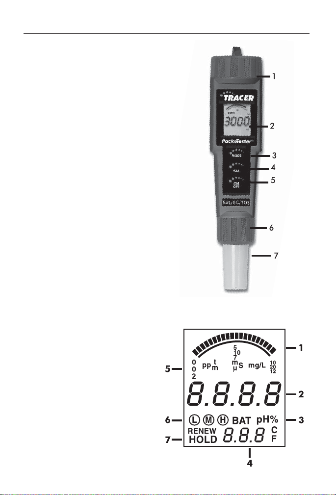
METER DESCRIPTION
Front Panel Description
1. Battery compartment cap
2. LCD Display
3. MODE/HOLD button - change
mode, hold data, store data
4. CAL/RECALL button - calibration,
change temperature units, recall data
5. ON/OFF button
6. Electrode Collar
7. Electrode
(Note: The Electrode cap is not shown)
TRACER Display
1. Bar graph reading
2. Measurement reading
3. BAT (low battery) indicator
4. Temperature display
5. Measurement units
6. Calibration range indicators
7. HOLD indicator
6
Page 7

BASIC OPERATION
Powering the TRACER
The Tracer uses four CR2032 Lithium Ion batteries. If the batteries are weak,
BAT indicator will appear on the display. Press the ON/OFF key to turn
the
the TRACER on or off. The auto power off feature will shut the TRACER off
automatically after 10 minutes after the last button push.
Automatic Calibration
When the TRACER is turned on, it will enter the Automatic Calibration
SELF and CAL will appear while the calibration is in progress. After the
mode.
calibration is completed, the
TDS Conversion Ratio
The TDS value is determined by multiplying the conductivity measurement
by a known conversion ratio factor. The meter allows the selection of a
conversion ratio factor in the range of 0.4 to 1.0. The selected ratio will vary
with application but is typically set between 0.5 and 0.7. In the salinity mode,
the ratio is fi xed at 0.5. The stored ratio factor will briefl y appear in the lower
temperature display when the meter is fi rst turned on or when changing the
measurement function to TDS.
To Change the TDS Conversion Ratio:
1. Turn the TRACER on.
2. Press and release the CAL/RECALL button twice.
The stored ratio will appear in the display.
3. Press the MODE/HOLD button to change the ratio
value in steps of 0.1.
4. When the desired ratio is displayed, press and release
the CAL/RECALL button to store the value and return
to the normal mode.
5. If no buttons are pressed for 5 seconds, the meter
will return to the measurement mode.
SELF and CAL display icons will extinguish.
7
Page 8

Changing the Displayed Temperature Units
To change the displayed temperature units between °F or °C:
1. With the TRACER off, press and hold the CAL/RECALL button.
2. With the CAL/RECALL button pressed, momentarily press the ON/OFF
button. When
button. The TRACER will return to the operational mode with the temperature displayed in the new units.
Data Hold
Press the MODE/HOLD button to freeze the current reading. The HOLD icon
will appear, the reading will be stored. Press the MODE/HOLD key to return
to normal operation.
Auto Power Off
The auto-power off feature will automatically shut the meter off 10 minutes
after the last button was pressed. To disable the auto-off feature:
1. Press the ON/OFF button to turn the meter on.
2. Wait for the
appear after turning on the meter. IMPORTANT: Review the instructions
for the next 3 steps before proceeding. Step 3 must be followed immediately by Step 4.
3. Press CAL/RECALL button once.
4. Press MODE/HOLD and ON/OFF buttons simultaneously. Quickly
release buttons.
SELF CAL appears in the display, release the CAL/RECALL
SELF display screen to appear. This is the second screen to
5. oFF will be displayed on the screen. Watch carefully. It will disappear
quickly.
6. The auto power off feature will be restored automatically when the meter
is turned off. Auto-off is the default function when the meter is turned on.
Low Battery Indicator
The “BAT” indicator will be displayed when the batteries become weak. Refer
to the maintenance section for battery replacement information
8
Page 9

TESTING
Getting Started
1. Remove the cap from the bottom of the TRACER to expose the electrode.
2. Before the fi rst use, rinse the electrode in deionized water and dry.
3. For best results, calibrate for conductivity with a standard in the expected
range of the sample. For maximum accuracy calibrate from low conductivity
value standards to high conductivity value standards.
Changing the Measurement Function
The meter can be set to measure Conductivity, TDS (ppm), TDS (mg/L) or
Salinity (ppm). To change the mode:
1. Turn the TRACER on.
2. Press and hold the MODE/HOLD button for 2 seconds. The display will
begin to scroll through the units.
μS or mS (Conductivity)
ppm (TDS)
ppm (Salinity “S”)
3. Release the MODE/HOLD key when the desired mode is displayed.
4. Note that the “HOLD” function can not be on when changing functions.
9
Page 10

Measurement
1. Fill a sample cup to the 20 mL line with the test sample. Sample depth
must be greater than or equal to 1.5 inches.
2. Immerse the TRACER electrode in the sample. Make sure the electrode is
completely submersed.
3. Press the ON/OFF button. (8888 and then SELF CAL
will appear in the display during the initial diagnostics).
4. Press and hold the MODE/HOLD button to scroll to
the desired measurement mode.
5. Slowly stir the sample with the TRACER to remove
air bubbles.
6. The meter will autorange to the proper range and the
100.9
72.3
MODE
CAL
ON
OFF
SAL/EC/TDS
∞F
reading will be displayed.
7. Rinse the electrode in distilled water. Replace the cap.
Measuring the TDS of Soil
1. Fill a 50 mL beaker with the soil sample. Tap the beaker lightly on a hard
surface to remove trapped air. Remove excess soil from the surface.
2. Empty the soil into a 250 mL
wide-mouth fl ask.
3. Add 100 mL of distilled water.
Stopper and shake vigorously.
4. Wait 30 minute. (Shake the fl ask
vigorously three or four times
during this period.)
5. Filter the contents of the fl ask.
4.01
Collect the fi ltrate in a beaker.
6. Rinse the electrode with distilled
or deionized water to remove
impurities.
10
Page 11

7. Press the ON/OFF button to turn the TRACER on. Make sure the meter is
in the TDS mode.
8. Immerse the electrode in the fi ltrate. Make sure the tip of the electrode is
completely immersed.
9. Stir the fi ltrate with the electrode to create a homogeneous solution.
10. Gently stir the fi ltrate with the electrode. Read the TDS value of the
fi ltrate from the display.
11. Rinse the electrode in distilled water. Replace the cap.
Storing Readings
1. After the reading is displayed press and hold the
MODE/HOLD button to store the current reading.
The meter will enter the HOLD mode and HOLD
will be displayed. The storage location number
will be displayed on the lower display followed by
the reading being stored.
2. Press the MODE/HOLD button to exit the HOLD
mode and return to normal operation.
3. If an attempt is made to store more than 25 readings,
the stored readings will be overwritten starting
with the fi rst reading.
Recalling Stored Readings
NOTE: First ensure that the HOLD symbol is not displayed. If it is, exit the HOLD
function by pressing the MODE/HOLD button.
1. Press the CAL/RECALL button and then press the MODE/HOLD button;
the location number (1 through 25) will briefl y appear and then the value
stored in that location will appear. The displayed units will fl ash, indicat-
ing that the storage recall mode is active.
10
2
20
15
10
s
2
1423
L
72.3
20
∫F
2. The last stored reading taken will be displayed fi rst. To advance to the
previously stored readings, press the MODE/HOLD button. The location
number is displayed fi rst, followed by the reading stored in that location.
3. To exit the storage mode, press the CAL/RECALL button and the
TRACER will return to normal operation after displaying “End”.
11
Page 12

Clearing the Stored Memory
Turn the TRACER on. Press and hold the ON/OFF button for 4 second the display
will briefl y display “clr” when the memory is cleared.
CALIBRATION
For the most accurate results, allow suffi cient time for the temperature of the
probe to reach the temperature of the sample before calibrating. This will be
indicated by a stable temperature reading on the display
Meter accuracy verifi cation should be performed on a periodic basis as needed.
If calibration is required, the meter must be in the salinity mode to perform a
calibration for salinity, or in the conductivity mode to perform calibrations for
conductivity, and TDS. The meter can perform a calibration and store the data
for one range in the salinity mode and each of the three ranges – low, medium
and high for the conductivity and TDS modes. The automatic calibration
recognition procedure will recognize salinity standard 3,000 ppm (medium)
and conductivity standards of 84 μS (Low), 1413 μS (Medium) or 12,880 μS
(12.88 μS) (High). (See Page 5). Always calibrate in the range closest to the
expected measurement value. For salinity samples within the range of 1,000 to
9,999 ppm salinity, calibrate with a 3,000 ppm calibration standard.
1. Fill a sample cup to 20 mL line with a calibration standard.
NOTE: The meter allows for a 1, 2, or 3 point calibration foe conductivity
and TDS. If calibration is done for more than one point, the lowest
concentration should be done fi rst to obtain the best accuracy. Calibrate
the ranges from low to high
2. Press the ON/OFF button to turn the TRACER on. Insert the electrode
into the standard. Tap or stir the sample with the Tracer to dislodge air
bubbles.
3. Press and hold the CAL/RECALL button for approximately 2 seconds.
“CAL” will appear and the display will fl ash.
4. The meter will automatically recognize and calibrate to the calibration
standard. The display will briefl y indicate “SA” and “End” and then
return to the measurement mode.
NOTE: “SA” will not appear if the calibration fails.
12
Page 13

5. The calibration range indicator will appear on the display for each range
that is calibrated during a power on cycle.
Low Range, 84 μS/cm
L
Medium Range, 1413 μS/cm or 3,000 ppm SaH
M
High Range, 12.88 mS/cm (12,880 μS/cm)
H
NOTE: Each time the calibration mode is entered all calibration range indicator
will be cleared, but only the calibration data for the currently selected range will
be replaced. In the conductivity/TDS modes, the calibrations for the other two
ranges will be saved even though the indicators for those ranges are no longer
displayed. Calibration of all three ranges must be performed during one power
on period for all three calibration range indicators to be displayed.
s
13
Page 14

OPERATIONAL MATRIX
Function/
Resulting Action Power Mode
On/Off On or
Off
Calibration On Con Press & hold CAL/
Store Reading On Any Momentary press of
Hold Release On Hold Momentary press of
Enter Memory
Retrieval
Scroll Stored
Readings
Exit Memory
Retrieval
Clear Stored
Memory
Change
Measurement Mode
On Any Momentary press
On Memory
On Memory
On Any
On Any Press and hold MODE/
Any Momentary press of
Recall
Recall
Measure
Mode
Key Press Sequence
ON/OFF button
RECALL button for 2
seconds until CAL is
displayed
MODE/HOLD button
MODE/HOLD button
of CAL/RECALL
button followed by a
momentary press of
MODE/HOLD button
within 4 seconds.
Momentary press of
MODE/HOLD button
Displays last in fi rst out.
Momentary press of
MODE/RECALL button
Press and hold the
ON/OFF button for 4
seconds until “clr” is
displayed.
HOLD button for 2
seconds. Modes will
scroll by until button is
released
14
Page 15

Function/
Resulting Action Power Mode
Enter CON/TDS
Ratio
Change CON/TDS
Ratio
Exit CON/TDS
Ratio
Change
Temperature Units
Override Auto
Power Off
Default Reset Off n/a Simultaneously press
On TDS
(ppm or
mg/L)
On TDS
(ppm or
mg/L)
On TDS
(ppm or
mg/L)
On n/a Press and hold CAL/
On Any Momentarily press
Key Press Sequence
Press and release
the CAL/RECALL
button twice in quick
succession.
Press and release
the CAL/RECALL
button twice in quick
succession. Momentary
press of MODE/HOLD
button. Each press
increases ratio by 0.1
from 0.4 to 1.0.
Momentary press of
CAL/RECALL button.
RECALL button then
momentarily press ON/
OFF button. Release
CAL/RECALL button
after“Self Cal” is
displayed.
CAL/RECALL button
then simultaneously
press and hold CAL/
RECALL and MODE/
HOLD buttons for 2
seconds until “oFF” is
displayed.
ON/OFF, CAL/
RECALL and MODE/
HOLD buttons
momentarily. “dFlt” will
be displayed.
15
Page 16

MAINTENANCE
Storage
1. Rinse the electrode in distilled or deionized water.
2. Store the electrode dry with the cap on.
3. Always rinse the electrode in deionized water between measurements to
avoid cross contamination. Double rinsing is recommended when high
accuracy is required.
Battery Replacement
1. Twist off the battery compartment cap.
2. Hold the battery housing in place with one fi nger. Remove the battery
carrier by pulling on the small tabs.
3. Replace the four CR2032 batteries. Observe polarity.
4. Replace the battery compartment cap.
Electrode Care
1. Always rinse the electrode in distilled or deionized water between
measurements to avoid cross-contamination of the samples. Double
rinsing is recommended when high accuracy is required.
2. Do not touch the electrodes. Touching the surface of the platinized
electrodes may damage and reduce the life of the electrodes.
Replacing the electrode
1. Unscrew and remove the electrode collar. Turn collar counter-clockwise.
2. Gently rock the electrode side to side, while pulling it away from the
meter, until it disconnects from the electrode socket.
3. To attach an electrode, align the slots and carefully plug the electrode into
the meter socket. CAUTION: Take care to align pins carefully. Bent or
broken pins will cause the meter to malfunction.
4. Firmly tighten the electrode collar to create a seal with the rubber gasket
between the electrode and the meter.
16
Page 17

Electrode Cleaning Recommendations
Do not soak the electrode in the solutions for longer than the recommended
length of time. To do so may cause a reference potential shift which will cause
a degradation in performance or failure. When cleaning the probe, do not
scratch or damage the platinized electrode surfaces.
Contaminant Cleaning Solution Procedure
Water soluble
substances
Grease and oil Warm water and
Heavy grease Alcohol Soak for a maximum of 5
Lime and
hydroxide
coatings and oil
Deionized water Soak or scrub with a soft
brush. Rinse thoroughly with
DI water and dry.
Soak or scrub with a soft
household detergant
10% Acetic acid Soak until coating dissolves,
brush, maximun 10 minutes.
Rinse thoroughly with DI
water and dry.
minutes. Scrub with a soft
brush. Rinse thoroughly with
DI water and dry.
maximum 5 minutes. Rinse
thoroughly with DI water and
dry.
17
Page 18

TROUBLESHOOTING
Problem Check Action
Reading is frozen HOLD mode Press MODE/HOLD button
to exit HOLD mode
“BAT” message Batteries low Replace batteries
Meter will not
calibrate
Meter will not turn
on
Unit will not respond
to any key presses
“_oL_” message Sample is out
Trapped air
bubbles
Dirty probe Clean probe
Damaged
probe
Contaminated
standards
Batteries low
or dead
Battery
polarity
Internal fault Perform hard reboot. Remove
of range
Tap probe or stir sample to
release air bubbles
Replace probe
Use fresh standards
Replace batteries
Replace batteries with correct
polarity
batteries, hold ON/OFF
button down for 5 seconds,
replace batteries
Dilute sample
18
Page 19

WARRANTY
LaMotte Company warrants this instrument to be free of defects in parts and
workmanship for 1 year from the date of shipment and the probe to be free of
defects in parts and workmanship for 6 months from the date of shipment. If it
should become necessary to return the instrument for service during or beyond
the warranty period, contact our Technical Service Department at 1-800-344-3100
or tech@lamotte.com for a return authorization number or visit www.lamotte.com
for troubleshooting help. The sender is responsible for shipping charges, freight,
insurance and proper packaging to prevent damage in transit. This warranty does
not apply to defects resulting from action of the user such as misuse, improper
wiring, operation outside of specifi cation, improper maintenance or repair, or
unauthorized modifi cation. LaMotte Company specifi cally disclaims any implied
warranties or merchantability or fi tness for a specifi c purpose and will not be
liable for any direct, indirect, incidental or consequential damages. LaMotte
Company’s total liability is limited to repair or replacement of the product. The
warranty set forth above is inclusive and no other warranty, whether written or
oral, is expressed or implied.
To register your meter with the LaMotte Service Department —
go to www.lamotte.com and choose SUPPORT on the top navigation bar.
19
Page 20

LaMOTTE COMPANY
Helping People Solve Analytical Challenges
PO Box 329 • Chestertown • Maryland • 21620 • USA
800-344-3100 • 410-778-3100 (Outside USA) • Fax 410-778-6394
Visit us on the web at www.lamotte.com
1749-01-MN 12/11
 Loading...