

Page 1
TRACER
POCKETESTER
TM
FLUORIDE
1756
Page 2

WARNING! This set contains chemicals
that may be harmful if misued. Read
cautions on individual containers
carefully. Not to be used by children
except under adult supervision.
Page 3

TRACER
FLUORIDE POCKETESTER
TM
• CODE 1756
Introduction .....................................................................................4
Specifi cations ..................................................................................4
Contents ..........................................................................................5
Parts & Accessories ........................................................................6
Meter Description
Front Panel Description ............................................................... 5
LCD Display .................................................................................6
Electrode Sensor Description .....................................................6
TISAB TesTabs Tablet Description ............................................... 6
Quick Start
Preparation ................................................................................... 7
Calibration .................................................................................... 7
Measurement ............................................................................... 8
Storage and Maintenance ...........................................................8
Operation
Preparation for use ...................................................................... 8
Powering the Fluoride TRACER .................................................. 9
Power-On Diagnostic ................................................................... 9
Calibration .................................................................................... 9
Calibration Frequency ................................................................ 10
Slope Adjustment ....................................................................... 10
Other Standards .......................................................................... 10
Measurement .............................................................................. 10
Temperature Units ....................................................................... 10
Auto-Power Off ............................................................................ 11
Disabling Auto-Power Off ........................................................... 11
Low Battery Indicator .................................................................. 11
Storing Readings ........................................................................ 11
Recalling Stored Readings ......................................................... 11
Clearing Stored Readings .......................................................... 11
Maintenance
Battery Replacement ..................................................................12
Replacing the Electrode ........................................................... 12
Electrode Storage ....................................................................... 12
Warranty ..........................................................................................13
Page 4

INTRODUCTION
The Fluoride TRACER is a system specifi cally designed for the quick and accurate
measurement of fl uoride ions in drinking water and other aqueous samples. Unlike
other electrode based systems the Fluoride TRACER consists of the sensing
electrode, measuring electronics, and the display in one convenient package. This
meter is shipped fully tested; with proper use, this instrument will provide years
of reliable service.
Features
• Automatic temperature compensation (±10oC of calibration temperature)
• Automatic calibration
• Stability sensing to optimize accuracy
• Internal Datalogger for storing up to 25 readings
• Direct reading of ppm units
• Direct reading of relative mV units
• Automatic shut down after 12 minutes to preserve battery life
• Internal error detection
• Convenient TISAB TesTab reagent
SPECIFICATIONS
Range 0.10 to 9.99ppm (mg/L)
Accuracy +/- 3.0% of reading or 0.1ppm whichever is greater
Resolution 0.1ppm
Display 2000 count, Dual function 3 ½ digit LCD with
Electrode Europium doped lanthanum fl uoride single crystal
Electrode Life 1 year minimum
Response Time 90% of change in less than 30 seconds (typical)
Operating Temp. Range 32 to 140°F (0 to 60°C)
ATC Range 32 to 140°F (0 to 60°C)
Measurement Storage 25 tagged (numbered) data sets with recall
Battery Power Four (4) CR2032 button batteries
Low Battery Indication ‘BAT’ appears on the LCD
Auto Power Off After 12 minutes of inactivity
Dimensions/Weight 1.4 x 6.8 x 1.6” (36 x 173 x 41mm); 7.4 oz (210g)
Bargraph, Display size: 24 mm x 20 mm
4
Page 5
CONTENTS
Fluoride TRACER Kit Code 1756
Includes:
Fluoride TRACER Body
Flat Surface Fluoride Electrode
TISAB TesTabs (20)
Tablet Crusher
Sample Cup
Lanyard
Protective Sensor Cap
Batteries, 3V (4)
PARTS & ACCESSORIES
TISAB TesTabs (100) Code 7024-J
Tablet Crusher Code 0175
Flat Surface Fluoride Electrode Code 1757
Fluoride Standarad, 1.0 ppm, 3800 mL Code 2798-M
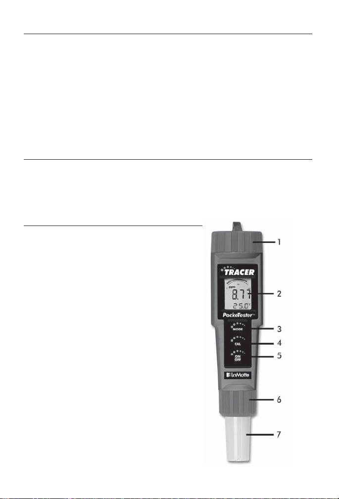
METER DESCRIPTION
Front Panel Description
1. Battery compartment cover
2. LCD Display
3. MODE/HOLD key
4. CAL/RECALL key
5. ON/OFF key
6. Electrode Retaining Collar (ring)
7. Electrode Sensor
(Note: The Electrode storage cap
is not shown)
5
Page 6

LCD Display
1. Bargraph reading
2. Measurement units
3. Main display
4. Low (L) and High (H)
Calibration icons
5. Data HOLD indicator
6. Low Battery indicator
7. Temperature display
Electrode Sensor Description
The sensing electrode is a europium doped lanthanum fl uoride single crystal that
has been incorporated into a removable sensing module that houses a reference
electrode and temperature measurement system. The high resistance electrode
signals are impedance converted to a low resistance output in the sensing module
to ensure stable and noise free performance.
TISAB TesTabs Tablet Description
The Fluoride TRACER allows the users to follow the ASTM and EPA standard
methodology using any of the TISAB reagents and standards already in use.
TISAB TesTabs contain all of the essential and approved chemicals that are
found in the usual TISAB reagents. The “dry” reagent does not contribute to
sample dilution.
6
Page 7

QUICK START
The following procedure describes a quick-start for the Fluoride TRACER using
the TISAB TesTabs. Detailed operating instructions can be found on the pages
that follow.
Preparation
1. Remove the Fluoride TRACER, tablets, electrode module and sample cup
from the box. Remove caps from module.
2. Fit the electrode module onto the end of the meter body, making sure that
the slots line up correctly, and tightly turn the module retaining ring to
secure the assembly.
3. Wipe the fl uoride crystal and reference junction with a damp tissue.
Calibration
1. Fill a sample cup to 20 mL with a 1.0 ppm fl uoride standard Add one
TISAB TesTab (7024). Crush tablet with Tablet Crusher (0175) and mix
until the tablet disintegrates. Or prepare a traditional 1.0 ppm fl uoride
standard and TISAB reagent, or use premade mixed TISAB and 1.0 ppm
standard. Pour 20 mLs of this standard solution into the sample cup.
2. Rinse the end of the Fluoride TRACER module in TISAB solution and
wipe thoroughly with paper tissue.
3. Place the Fluoride TRACER in the 1.0 ppm standard/TISAB mixture.
4. Switch the instrument on using the ON/OFF key. The instrument will
now go through its internal calibration.
5. The 1.0 ppm reading will stabilize in approximately 35 seconds and the
instrument will enter HOLD mode.
6. When in HOLD mode press the CAL key and hold until 1.0 ppm and
‘CAL’ appear in the display. Release the CAL key.
7. Wait until the display stops blinking; the instrument will enter the HOLD
mode.
8. The instrument is now calibrated and ready for use or calibration with a
second standard.
7
Page 8

Measurement
1. Prepare unknown solution by adding one TISAB TesTab (7024) to 20 mL
of the sample. Crush tablet with Tablet Crusher (0175) and mix until the
tablet dissolves. Or use another TISAB reagent system. Thoroughly wipe
the end of the Fluoride Tracer.
2. Place the Fluoride TRACER into the prepared unknown sample.
3. If the display is indicating ‘HOLD’ press the HOLD key to enter the Measure mode. (The HOLD display will switch off).
4. After approximately 35 seconds the instrument will display the value of
the unknown concentration. Refer to the Maintenance Section for battery
replacement information.
5. The readings can be stored in memory by pressing the MODE/HOLD key
for approximately 3 seconds.
Storage and maintenance
1. After use, store the electrode in an analyzed sample. (Fluoride standards
plus TISAB tablet)
2. Thoroughly wipe the sensor with paper tissue. The fl at ended sensors can
be wiped vigorously.
3. The fl uoride module can be replaced once the automatic calibration no
longer suffi ciently calibrates the instrument.
4. Other maintenance information is provided in a later section of this guide.
OPERATION
Preparation for use
1. Remove the Fluoride TRACER, tablets, electrode module and sample cup
from the box. Remove caps from module.
2. Fit the electrode module onto the end of the meter body, making sure that
the slots line up correctly, and tightly turn the module retaining ring to
secure the assembly.
3. Wipe the fl uoride crystal and reference junction with a damp tissue.
(Cleaning techniques are addressed later in this guide).
8
Page 9

Powering the Fluoride TRACER
The Fluoride TRACER uses four (4) CR2032 lithium ion batteries. Press the ON/
OFF key to turn the meter on or off. If the batteries are weak, the ‘BAT’ indicator
appears on the LCD. The auto power off feature shuts the meter off automatically
after approximately 12 minutes of inactivity. The auto power off feature may be
temporarily disabled for convenience or for extended polarization time.
Power-On Diagnostics
1. When the meter is switched ON the LCD displays ‘SELF’ and ‘CAL’
while the meter runs a diagnostic routine.
2. During this time the meter is recalling the user calibration data, performing self diagnostics & initializing the circuitry.
3. When completed, the meter proceeds to the normal measurement mode.
Calibration
The Fluoride TRACER can be calibrated between 1.0 ppm and 10.0 ppm or
between 0.5 and 5.0 ppm Fluoride ion. The following calibration procedure
assumes the normal 1.0 to 10 ppm range has been chosen.
1. Fill a sample cup to 20 mL with a 1 ppm fl uoride standard Add one
TISAB TesTab (7024). Crush tablet with Tablet Crusher (0175) and mix
until the tablet disintegrates. Or prepare a traditional 1.0 ppm fl uoride
standard and TISAB reagent, or use pre made mixed TISAB and 1.0 ppm
standard. Pour 20 mLs of this standard solution into the sample cup.
2. Rinse the end of the Fluoride TRACER module in TISAB solution and
wipe thoroughly with paper tissue.
3. Place the Fluoride TRACER in the 1.0 ppm standard/TISAB solution and
switch the instrument ON using the ON/OFF key. The instrument will
now run its self-calibration.
4. The instrument will enter the HOLD mode when stabilized in the 1.0 ppm
solution.
5. Press the CAL key; ‘CAL’ will appear in the display followed by 0.5ppm
and 5.0 ppm. Continue holding until 1.0 ppm is shown. Release the CAL
key. After the display stops blinking the instrument will enter the HOLD
mode.
6. For a 2 point calibration, repeat the calibration procedure with a 10.0 ppm
standard.
7. The instrument is now calibrated and ready for use. The circled ‘L’ and
‘H’ icons on the display indicate that the low range (L) and high range
(H) calibrations have been completed.
9
Page 10

Calibration Frequency
A 1 point calibration is adequate prior to each new measurement batch or if more
than 24 hours has elapsed since the last calibration. A 2 point calibration should
be performed if the meter is new or has not been calibrated for 5 days.
Slope Adjustment
1. Slope adjustment, although not a frequent requirement, can be carried
out by following the instructions in Calibration above and by calibrating
with a 10.0 ppm standard after calibrating with the 1.0 ppm standard.
2. Press the CAL key until 10.0 ppm appears. Slope adjustment is then
complete.
Other standards
As mentioned the Fluoride TRACER can also be calibrated between 0.5 and 5.0
ppm Fluoride. Follow the calibration instructions above but substitute 0.5 ppm
for 1.0 ppm and 5.0 ppm for 10.0 ppm.
Measurements
1. Prepare an unknown solution by adding, crushing, and dissolving one TISAB TesTab (7024) in 20 mL of the sample or by adding TISAB reagent
to the sample in the same dilution ratio as for the calibration procedure.
Mix thoroughly.
2. Rinse the end of the Fluoride TRACER.
3. Place the Fluoride TRACER into the prepared unknown sample. If the
instrument is in the HOLD mode, press MODE/HOLD to unlock HOLD.
4. After 25 seconds, the instrument will display the value of the unknown
concentration and will then enter the HOLD mode.
Note: The readings can be stored in the memory by pressing the MODE/
HOLD key for approximately 3 seconds as explained in a subsequent section of this user guide.
Temperature Units (ºF / ºC)
1. With the unit OFF, press and hold the CAL/RECALL key.
2. With the CAL/RECALL key depressed, momentarily press the ON/OFF
button to turn the unit ON.
3. The CAL/RECALL key can be released when ‘Self Cal’ is shown in the
display.
4. To switch back to the previous unit of measure, repeat steps 1 through 3.
10
Page 11

Auto-Power OFF Feature
The auto power off feature automatically shuts the meter off 12 minutes after the
most recent button press.
Disabling the Auto-Power OFF Feature
With the unit ON, momentarily press the CAL/RECALL key, then quickly press
and hold both the MODE/HOLD and ON/OFF key until ‘oFF’ is displayed. To
restore the Auto Power Off Feature (auto power OFF enable) simply turn the
meter off and on again using the ON/OFF key.
Low Battery Indication
When the battery voltage falls below the operating threshold, ‘BAT’ will
appear on the display. Refer to the Maintenance section for battery replacement
information.
Storing Readings
Up to 25 readings can be stored in memory for later recall.
1. With the meter in the HOLD mode, press and hold the MODE/HOLD key
for 3 seconds to store a reading. Release the key when the memory location number appears on the lower display.
2. After approximately 30 seconds (measurement duration) the meter will
return to the HOLD mode and another reading can then be stored.
3. If more than 25 readings are stored, previously stored readings (starting
with reading number 1) are overwritten.
Recalling Stored Readings
1. Momentarily press the CAL/RECALL key and then within 4 seconds
momentarily press the MODE/HOLD key. The last stored data point
location will be displayed (1 to 25). Each time the MODE/HOLD button
is momentarily pressed the next most recently stored data key will be
displayed.
2. After the last data point is displayed, pressing the MODE/HOLDkey
again returns the display to the beginning of the list.
3. Pressing the CAL/RECALL key at anytime stops the data retrieval process and returns the meter to the normal measurement mode.
Clearing Stored Readings
4. With the unit ON press and hold the ON/OFF key for 4 seconds.
5. When ‘clr’ is shown in the main display the memory is cleared.
11
Page 12

Maintenance
Battery Replacement
1. Twist off the battery compartment cover.
2. Holding the battery housing in place with a fi nger, pull out the battery
carrier using the two small tabs.
3. Replace the four (4) CR2032 batteries observing proper polarity.
4. Replace the battery carrier, reattach the battery compartment cap and
tighten securely.
Electrode Replacement
1. To remove the electrode, fi rst turn the instrument OFF and then unscrew
and remove the electrode retaining collar. (Turn the collar counter-clockwise to remove).
2. Gently rock the electrode from side to side, pulling it away from the
meter until it disconnects.
3. To attach an electrode, align the positioning “keys” on the electrode and
the main body housing and then carefully push the electrode into the
meter socket until it is fully seated. CAUTION: Take care to align pins
carefully. Bent or broken pins will cause the meter to malfunction.
4. Tighten the electrode retaining collar fi rmly enough to seal the electrode
with the meter.
Electrode Storage
1. The module and can be stored wet or dry. If stored dry it will be necessary to allow approximately 15 minutes of soaking in a fl uoride solution
before the specifi ed performance can be achieved. It is recommended that
the electrode be stored wet in the last test solution used by the instrument
(fl uoride ion plus TISAB reagent).
2. The instrument will give an error code when the electrode can no longer
be calibrated.
3. If the instrument will not calibrate, clean the fl uoride electrode surface
and recalibrate the instrument. If the meter still does not calibrate, replace
the electrode.
12
Page 13

WARRANTY
LaMotte Company warrants this instrument to be free of defects in parts and
workmanship for 1 year from the date of shipment and warrants this probe to
be free of defects in parts and workmanship for 6 months from the date of
shipment. If it should become necessary to return the instrument for service
during or beyond the warranty period, contact our Technical Service Department
at 1-800-344-3100 or tech@lamotte.com for a return authorization number or
visit www.lamotte.com for troubleshooting help. The sender is responsible for
shipping charges, freight, insurance and proper packaging to prevent damage in
transit. This warranty does not apply to defects resulting from action of the
user such as misuse, improper wiring, operation outside of specifi cation, improper
maintenance or repair, or unauthorized modifi cation. LaMotte Company
specifi cally disclaims any implied warranties or merchantability or fi tness for
a specifi c purpose and will not be liable for any direct, indirect, incidental or
consequential damages. LaMotte Company’s total liability is limited to repair or
replacement of the product. The warranty set forth above is inclusive and no
other warranty, whether written or oral, is expressed or implied.
To register your meter with the LaMotte Service Department, go to www.lamotte.com
and choose SUPPORT on the top navigation bar.
13
Page 14

0
Page 15

0
Page 16

LaMOTTE COMPANY
Helping People Solve Analytical Challenges
PO Box 329 • Chestertown • Maryland • 21620 • USA
800-344-3100 • 410-778-3100 (Outside USA) • Fax 410-778-6394
Visit us on the web at www.lamotte.com
1756-MN 6/12
 Loading...