

Page 1
TRACER
P
POCKETESTER
OR
ä
CODE 1742
Page 2

Page 3

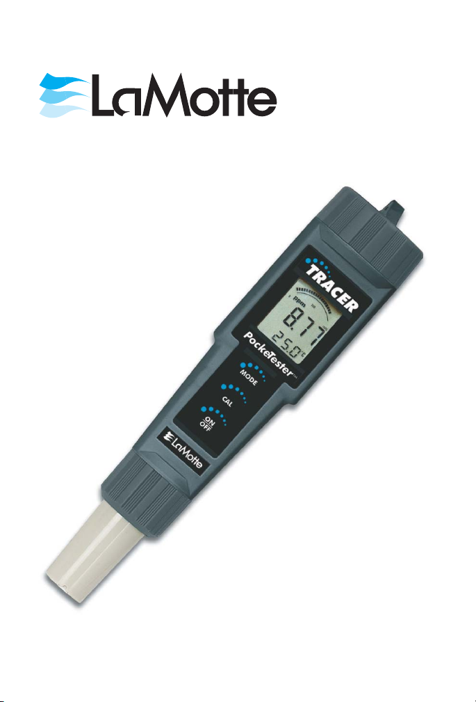
TRACER
ORP POCKETESTER
CODE 1742
Table of Contents
Introduction .............................. 4
Specifications ............................. 4
Contents ................................ 4
Parts & Accessories .......................... 4
Meter Description
Front Panel Description ..................... 5
TRACER Display......................... 5
Basic Operation
Powering the TRACER ..................... 6
Electrode Recognition ...................... 6
Automatic Calibration ...................... 6
Data Hold............................. 6
ORP Testing
Overview ............................. 6
ORP Display ........................... 6
Getting Started .......................... 6
ORP Measurement ........................ 6
Storing Readings ......................... 7
Recalling Stored Readings .................... 7
Maintenance
Storage .............................. 8
Battery Replacement ....................... 8
Cleaning & Conditioning the Electrode ............. 8
Troubleshooting ............................ 9
Replacing the Electrode ........................ 9
Expand Your TRACER ........................10
Warranty ............................... 10
TM
3
Page 4

Introduction
Congratulations on your purchase of the TRACER ORP PockeTester.
The advantages of the TRACER to the user include: Easy to use and
maintain, high accuracy, automatic calibration, and fast response. The
TRACER a 15-reading memory storage. Careful use and maintenance
will provide years of reliable service.
Specifications
Display Multifunction LCD with Bar graph
Operating Conditions 32 to 122°F (0 to 50°C) and < 80% RH
ORP Range & Accuracy ±999mV/±4mV
Measurement storage 15 tagged (numbered) readings
Power Four CR2032 button batteries (see Page
6)
Low battery indication ‘BAT’ appears on the LCD
Auto power off After 10 minutes of inactivity
Contents
ORP TRACER PockeTester Kit, ±999mV Range Code 1742
Includes Sample Cup w/cap*
*Not sold individually. See below.
Parts & Accessories
ORP Replacement Electrode Code 1734
Weighted Stand w/Sample Cups (5) Code 1746
Sample Cups w/caps (24) Code 1745
4
Page 5

Meter Description
Front Panel Description
1. Battery compartment cap
2. LCD Display
3. MODE/HOLD button
4. CAL/RECALL button
5. ON/OFF button
6. Electrode Collar
7. Electrode
(Note: The Electrode cap is not shown)
Display Description
1
. Reading
2
. Units
3
. Bargraph
4
. Data Hold
5
. Scale
6
. Low Battery
5
Page 6

Basic Operation
Powering the TRACER
If the batteries are weak, the
Press the ON/OFF key to turn the TRACER on or off. The auto power
off feature will shut the TRACER off automatically after 10 minutes of
inactivity.
Electrode Recognition
When the TRACER is turned on, it will recognize the type of electrode
that is connected and will display the appropriate unit of measure. An
electrode must be attached before turning the meter on.
Automatic Calibration
When the TRACER is turned on, it will enter the Automatic
Calibration mode. ‘SELF’ and ‘CAL’ will appear on the display while
calibration is in progress. After the calibration is completed, the ‘SELF’
and ‘CAL’ display icons will extinguish and both the main display and
the bargraph will read ORP in mV.
Data Hold
Press the MODE/HOLD button to freeze the current reading. The
display icon will appear along with the held reading. The held reading
will be stored in the next 15-reading storage location. Press the
MODE/HOLD button to return to normal operation.
TESTING
Overview
ORP is the abbreviation for Oxidation Reduction Potential and
represents the oxidizing or reducing nature of a solution. The overall
reactive tendency of a solution can be determined from ORP
measurements.
Display
When the electrode is placed in a solution, the main display and bar
graph will indicate the ORP reading. Readings flash until they have
stabilized. The bar graph is ‘center zero’, i.e. at 500mV there is no
display. As the readings increase from 0 to 1000 mV the bar will move
from the left to the right.
Getting Started
1. Remove the cap from the bottom of the TRACER to expose the
flat surface electrode and reference junction.
2. White KCL crystals may be present in the cap. Rinse the crystals
with tap water.
BAT indicator will appear on the LCD.
HOLD
6
Page 7

ORP Measurement
1. Press the ON/OFF button to turn the meter on. Place the electrode
½” to 1” into the test sample .
2. Stir once and let the reading stabilize for 1 to 3 minutes.
The main display will indicate the ORP in numeric units from 0 to
1000mV. The bar graph will also display the ORP value. As the
ORP increases, the bar graph will move from left to right.
3. Press the ON/OFF button to turn the meter off. Rinse the electrode
with distilled water. Replace cap.
Storing Readings
1. After the reading is made press the MODE/HOLD button to store
the current reading. The
location number will also be displayed followed by the reading
being stored.
2. Press the MODE/HOLD
button to return to normal
operation.
3. Repeat step 1 to store the next
reading.
4. If an attempt is made to store
more than 15 readings, the
stored readings (starting with
the first reading) will be overwritten.
Recalling Stored Readings
NOTE: First ensure that the
the HOLD function by pressing the MODE/HOLD button.
1. Press the CAL/RECALL button once and then press the MODE
button immediately after
through 15) will flash. If the CAL mode is accidentally accessed
(display flashing), press the CAL/RECALL button again to exit.
2. The last stored reading taken will be displayed first. To advance
through the stored readings, press the MODE/HOLD button. The
location number is displayed first, followed by the reading stored in
that location.
3. To exit the recall mode, press the CAL/RECALL button and the
TRACER will return to normal operation.
If the batteries are removed, any stored readings will be discarded.
HOLD icon will be displayed. The storage
HOLD symbol is not displayed. If it is, exit
CAL is displayed; the location number (1
7
Page 8

MAINTENANCE
Storage
To preserve electrode life keep the sponge in the protective cap soaked
with tap water. Dot not use deionized or distilled water.Cap TRACER
when not in use. Store vertically.
Battery Replacement
1. Twist off the battery compartment cap.
2. Hold the battery housing in place with one finger. Remove the
battery carrier by pulling on the small tabs.
3. Replace the four CR2032 batteries. Observe polarity.
4. Replace the battery compartment cap.
NOTE: If the batteries are removed, stored data will be cleared.
Factory calibrations will be retained.
8
Page 9

Troubleshooting
Problem Cause Action
Power on but no
display
Unstable readings Electrode Immerse electrode more deeply in
Static charge Wiping electrode Rinse electrode and blot. Do not wipe
Same readings in
different samples
Display frozen HOLD function Press MODE or turn meter off
Steady “-1 ” display Wait Reading not stable yet
Batteries Insert batteries
Batteries Verify correct polarity
Batteries Replace batteries
sample
Electrode Condition electrode before first use.
Electrode Remove air bubbles caught under
Electrode Clean electrode
Electrode Replace electrode
Cracked or broken
electrode
Button response Remove batteries (stored data will be
Soak in tap water for 10 minutes.
electrode
electrode
Replace electrode. Avoid plunging
electrode into bottom of container and
stir bars.
lost)
Replacing the Electrode
The TRACER is shipped with an electrode attached. If the electrode
needs to be replaced, follow these steps for removing and connecting
electrodes.
1. Turn meter off.
2. To remove the electrode, turn the collar counter-clockwise and
remove it.
3. Gently rock the electrode from side to side, pulling it downwards,
until it disconnects from the meter.
4. To attach an electrode, carefully plug the electrode into the meter
socket. Note that the electrode connector is keyed to ensure a
proper connection.
5. Tighten the electrode collar firmly enough to make a good seal. A
rubber gasket will seal the electrode with the meter.
9
Page 10

Expand Your TRACER
Interchangeable electrodes are available to convert the ORP TRACER
to a Total Chlorine TRACER or a pH TRACER.
Remember to ask for instructions and appropriate reagent or buffer
tablets when ordering Total Chlorine or pH electrodes.
Total Chlorine TRACER Electrode, 0.00-10.00 ppm Code 1732
The Total Chlorine TRACER Electrode (Code
1732) requires the use of TRACER TCL Tablets.
Order Code 7044A-J (100 pack).
pH TRACER Electrode, 0.00 - 14.00 pH Code 1733
The pH TRACER Electrode is used with pH 4.0, 7.0
and 10.0 buffers. Order using the following codes:
pH 4.0 Mini Buffer Tablets (100) Code 3983A-J
pH 7.0 Mini Buffer Tablets (100) Code 3984A-J
pH 10.0 Mini Buffer Tablets (100) Code 3985A-J
WARRANTY
This Instrument is guaranteed to be free from defects in material and
workmanship for a period of one (1) year from the original purchase
date. The probe is guaranteed to be free from defects in material and
workmanship for a period of six (6) months from the original purchase
date. In the event that a defect is found during the warranty time
frame, LaMotte Company agrees that it will be repaired or replaced
without charge except for the transportation costs. This guarantee does
not cover batteries.
This product can not be returned without a return authorization
number from LaMotte Company. For warranty support or a Return
Authorization Number, contact LaMotte Company at 1-800-344-3100
or tech@lamotte.com.
Limitations
This guarantee is void under the following circumstances:
• Damage due to operator negligence, misuse, accident or improper
application.
• Damage or alterations from attempted repairs by an unauthorized
(non-LaMotte) service.
• Damage due to improper power source, AC adapter or battery.
• Damage caused by acts of God or natural disaster.
• Damage occurred while in transit with a shipping carrier.
10
Page 11

LaMotte Company will service and repair out-of-warranty products at a
nominal charge.
Page 12

LaMOTTE COMPANY
Helping People Solve Analytical Challenges
PO Box 329 • Chestertown • Maryland • 21620 • USA
800-344-3100 • 410-778-3100 (Outside U.S.A.) • Fax 410-778-6394
Visit us on the web at www.lamotte.com
®
5/08
 Loading...