

Page 1
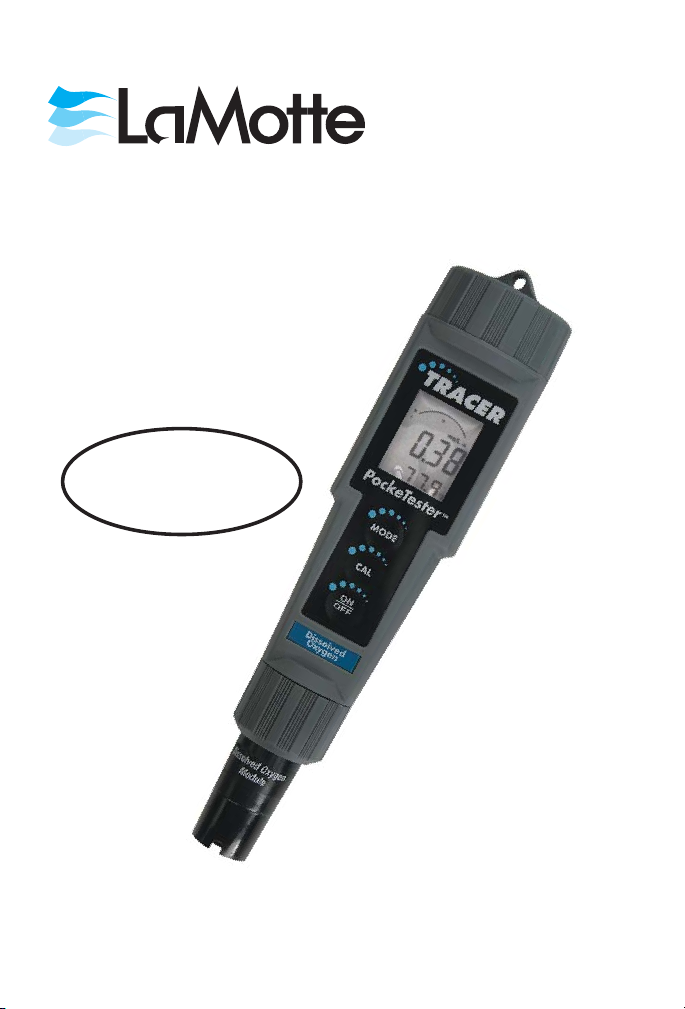
DISSOLVED OXYGEN
TRACER
POCKETESTER
See Short form Instruction
on the back cover. Read the
entire manual before use.
TM
CODE 1761
Page 2

WARNING! This set contains chemicals
that may be harmful if misused. Read
cautions on individual containers
carefully. Not to be used by children
except under adult supervision
Page 3

TRACER
DISSOLVED OXYGEN • CODE 1761
Table of Contents
Introduction ................................ 4
Specifications ............................... 4
Contents ..................................
Parts & Accessories ............................ 5
Meter Description ............................. 6
Front Panel Description.......................... 6
TRACER Display ............................. 6
SetUp................................... 7
Polarization ................................ 7
Calibration ................................ 7
Measuring Dissolved Oxygen ....................... 8
Basic Operation .............................. 8
Powering the TRACER.......................... 9
Changing the Temperature Units .................... 9
Changing Salinity Compensation .................... 9
Changing the Altitude Compensation .................. 9
Changing Measurement Units ...................... 9
Data Hold ................................ 10
Low Battery Indicator .......................... 10
Storing Readings ............................ 10
Recalling Stored Readings........................ 10
Clearing Stored Memory ........................ 11
Disable Auto Power Off ......................... 11
Calibration ................................ 11
Calibration................................ 12
Zero Oxygen Calibration....................... 13-14
Operational Matrix ............................ 15
Maintenance ............................... 15
Battery Replacement .......................... 15
Replacing the Electrode ......................... 15
Storage.................................. 15
Electrode Cleaning Recommendations ................. 16
Membrane Cap Assembly Replacement ............... 16-17
Troubleshooting ............................. 18
Warranty ................................. 19
Short Form instructions ..................... back cover
5
3
Page 4
INTRODUCTION
Congratulations on your purchase of the Dissolved Oxygen/Temperature
Tracer. Units of measure are % saturation, mg/L or ppm for dissolved
oxygen and °C or °F for temperature. Advanced features include data hold,
25 point memory, auto shut off, automatic temperature compensation, and
salinity/altitude compensation. Careful use and maintenance will provide
years of reliable service.
SPECIFICATIONS
Display Dual function 3 ½ digit LCD with Bar Graph
Display size: 24 mm x 20 mm
Range % Sat: 0 to 200.0%
DO: 0 to 20.00 mg/L, 0 to 20.00 ppm
Temp: 0 to 50°C, 32 to 122°F
Resolution: % Sat: 0.1%
DO: 0.01 mg/L, 0.01 ppm
Temp: 0.1°C, 0.1°F (0 to 99°F),
1.0 °F (>100 °F)
Accuracy: % Sat: ±2.0% full scale
DO: ±2% full scale
Temp: ±1.0°C, ±1.8°F
Operating Temperature
0 to 50°C (32 to 122°F)
Range
Automatic Temperature
0 to 50°C (32 to 122°F)
Compensation
Salinity Compensation 0 to 50 ppt in 1 ppt increments
Altitude Compensation 0 to 20,000 ft in 1000 ft increments
Sensor Polarographic type
Membrane Bonded membrane cap with threaded fitting
Data Storage 25 tagged (numbered) data sets with recall
Auto Power Off After 10 minutes of no button presses
(override available)
Battery Power Four 303/357 button batteries
Low Battery Indicator ‘BAT’ appears on LCD
Dimensions 1.4 X 6.8 X 1.6 inches (36 X 173 X 41 mm)
4
Page 5

CONTENTS
Dissolved Oxygen TRACER Kit Code 1761
Includes:
DO TRACER Body
DO Bonded Membrane Cap Assemblies (2)
Electrolyte Solution Code D0600-EL
Sample cup
Lanyard
PARTS & ACCESSORIES
DO Replacement Sensor Kit (sensor module,
membrane cap assembly, electrolyte solution)
DO Membrane Cap Kit (6 membrane cap
assemblies, electrolyte solution, Polishing Strips)
DO Extension Cable, 1 meter (with probe guard
and weight)
DO Extension Cable, 5 meters (with probe guard
and weight)
Code1762
Code 1761M
Code 1763
Code 1764
5
Page 6
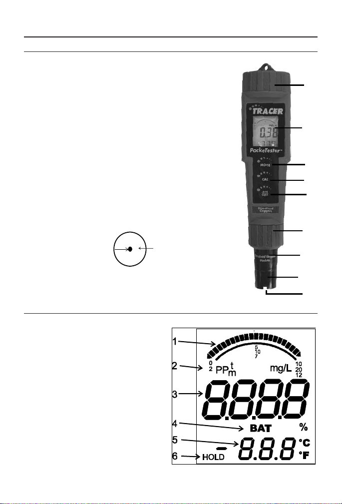
METER DESCRIPTION
Front Panel Description
1.
Battery compartment cap
2. LCD display
3. MODE/HOLD button – change
mode, hold data, store data
4. CAL/RECALL button –
calibration, change temperature
units, recall data
5. ON/OFF button
6. Electrode retaining collar
7. Dissolved oxygen sensor
8. Bonded membrane cap assembly
9. Membrane Cathode
(Note: The electrode storage cap is not shown.)
Bottom View of Electrode
Cathode
TRACER Display
1.
Bar graph reading
2. Measurement units
3. Main display
4. Battery indicator
5. Temperature display
6. Reading hold indicator
Membrane
1
2
3
4
5
6
7
8
9
6
Page 7

SET UP
Polarization
It will take 2-3 minutes for the probe to polarize. When the meter is first
turned on very high oxygen readings will be displayed. However, these
readings will drop to a steady state as oxygen that was absorbed in the
electrolyte solution, while the meter was turned off, is reduced. Once this
steady state is reached, polarization is complete. The meter may have to be
calibrated after polarization.
1. The meter must be in the % saturation mode. If the meter is not in the
% saturation mode, press and hold the MODE/HOLD button to change
to the next unit of measure in the sequence:
% saturation
l
dissolved oxygen, mg/L
l
dissolved oxygen, ppm
l
Release the MODE/HOLD button when % saturation is displayed.
2. Observe the % saturation reading on the display. The electrode will be
polarized when the reading has stopped drifting and is steady. If the %
saturation value that is displayed is 101.7%, proceed to
Testing/Measurement.
3. If the displayed % saturation is not 101.7% the meter must be
calibrated.
NOTE: The auto-power off feature will automatically shut the meter off 10
minutes after the last button was pressed. If the initial polarization of the
electrode takes longer than 10 minutes, the auto-power off feature must be
disabled. See page 11.
Calibration
Calibration should be performed daily. The electrode membrane must be
clean and dry or the calibration will be incorrect. This is a water saturated
air calibration.
1. Press the ON/OFF button to turn the meter on.
2. The meter must be in the % saturation mode. If the meter is not in the
% saturation mode, press and hold the MODE/HOLD button to change
to the next unit of measure in the sequence:
l
% saturation
l
dissolved oxygen, mg/L
l
dissolved oxygen, ppm
Release the MODE/HOLD button when % saturation is displayed.
3. Observe the % saturation reading on the display. Wait until the reading
is stable.
7
Page 8

4. The electrode membrane must be clean and dry or the calibration will
be incorrect. Moisten the sponge in the electrode storage cap with
distilled or tap water. The sponge should be moist but not soaked. Place
the electrode storage cap on the meter.
5. When the reading is stable, press and hold the CAL/RECALL button
for 2 seconds until CAL appears on the display. Release the button.
6. The display will blink until it is stable. 101.7% and “SA” will appear on
the display. When the calibration is complete, “END” will appear on
the display and the meter will return to the measurement mode.
Note: “SA” will not appear if the calibration fails.
7. The % saturation value that is displayed should be 101.7%. If not, allow
electrode to fully polarize, repeat step 5 until the display reads 101.7%.
8. Proceed to Testing/Measurement
MEASURING DISSOLVED OXYGEN
1.
Press the ON/OFF button to turn the meter on. SELF and CAL will
appear on the display as the TRACER self calibrates.
2. Select the desired units of measure by pressing and holding the
MODE/HOLD button.
3. Place the meter in the sample to be measured. Do not immerse the
electrode above the bottom edge of the electrode collar.
4. Slowly use the meter to stir the sample or use a magnetic stirrer. The
probe consumes oxygen at the measuring surface. Constant sample
movement is required to obtain representative results.
5. The display will blink until a stable reading is achieved. Record the
reading.
NOTE: For maximum accuracy, allow sufficient time for the temperature of
the probe to reach the temperature of the sample before taking a reading.
Allow the meter time to settle to the final measurement value before taking
a reading. The greater the difference in temperature between the electrode
and the sample, the longer it will take for the reading to stabilize. It may
take 10 seconds to 5 minutes.
6. Press the ON/OFF button to turn the meter off. Rinse the electrode in
distilled water. Replace the cap.
BASIC OPERATION
Powering the TRACER
Press the ON/OFF button to turn the TRACER on or off. If the batteries
are weak, the BAT indicator will appear on the display. The auto power off
feature will shut the TRACER off automatically 10 minutes after the last
button push. The auto power off feature may be temporarily disabled for
convenience or for extended polarization time during the initial set up of
the meter or when a new membrane cap is installed. (see page 9)
8
Page 9

Turn-On Diagnostics
When the meter is turned on, the “SELF” and “CAL” will be displayed and
the meter will enter into a diagnostic mode. During this time the meter will
recall the User Calibration data, perform self-diagnostics and initialize the
circuitry.
Changing the Temperature Units
To change the displayed temperature units between °C or °F:
1. With the TRACER off, press and hold the CAL/RECALL button.
2. With the CAL/RECALL button pressed, momentarily press the
ON/OFF button to turn the meter on and toggle between °C and °F
temperature units.
3. Release the CAL/RECALL button when Self Cal is displayed.
Changing Salinity Compensation
1.
Press the ON/OFF button to turn the meter on.
2. Press and release the CAL/RECALL button twice. “SAL “ will be
displayed.
3. Press the MODE/HOLD button. Each press of the MODE/HOLD
button will increase the salinity compensation value by 1 ppt (part per
thousand). The available salinity compensation range is 0 to 50 ppt.
4. Press and release the CAL/RECALL button to save the compensation
setting and return to the measurement mode.
Changing the Altitude Compensation
1.
Press the ON/OFF button to turn the meter on.
2. Press and release the CAL/RECALL button twice within 4 seconds.
“SAL “ will be displayed.
3. Press and hold the CAL/RECALL button for 2 seconds to enter the
Altitude Mode. “Ald” will be displayed.
4. The factory default value is sea level. Press the MODE/HOLD button.
Each press of the MODE/HOLD button will increase the altitude
compensation value by 1000 ft. The available altitude compensation
range is 0 to 20,000 ft.
5. Press and release the CAL/RECALL button to save the compensation
setting and return to the measurement mode.
Changing the Measurement Units
To change the mode:
1. Press the ON/OFF button to turn the meter on. The unit of measure
selected when the meter was last turned off will remain on the display.
2. Press and hold the MODE/HOLD button for 2 seconds to scroll through
the units of measure sequence:
9
Page 10

% saturation
l
dissolved oxygen, mg/L
l
dissolved oxygen, ppm
l
3.
Release the MODE/HOLD button when the desired mode is displayed.
The meter will return to the measurement mode.
Note: The measurement units cannot be changed while the HOLD function
is on. If “HOLD” is displayed in the lower left corner of the display, briefly
press the MODE/HOLD button to turn the HOLD function off.
Data Hold
Press the MODE/HOLD button to freeze the current reading. The HOLD
icon will appear. Press the MODE/HOLD key to return to normal
operation.
Low Battery Indicator
The “BAT” indicator will be displayed when the battery voltage falls below
the operating threshold. Refer to the Maintenance section for battery
replacement information.
Storing Readings
1.
After the reading is displayed press and hold the MODE/HOLD button
to store the current reading. The meter will enter the HOLD mode and
HOLD will be displayed. The storage location number will be displayed
on the lower display followed by the reading being stored.
2. Press the MODE/HOLD button to exit the HOLD mode and return to
normal operation.
3. To store the next reading, press the MODE/HOLD button when the
reading is displayed.
4. If an attempt is made to store more than 25 readings, the stored readings
will be overwritten starting with the first reading.
Recalling Stored Readings
1.
Press the CAL/RECALL button once and then press the MODE/HOLD
button within 4 seconds. The last stored data point will be displayed (1
through 25).
2. To advance to the next most recently stored reading, press the
MODE/HOLD button.
3. After the last stored data point is displayed, press the MODE/HOLD
button to return to the beginning of the list.
4. To stop the data retrieval process and return to the normal
measurement mode, press the CAL/RECALL button at any time.
Note: Stored readings can not be recalled if the HOLD function is on. If the
HOLD symbol is displayed, exit the HOLD function by pressing the
10
Page 11

MODE/HOLD button. If there is no data stored in the memory, “END” will
be displayed briefly and the meter will return to the previous mode.
Clearing Stored Memory
Turn the TRACER on. Press and hold the ON/OFF button for 4 seconds.
The display will briefly display “clr” when the memory has been cleared.
Disable Auto Power Off
The auto-power off feature will automatically shut the meter off 10 minutes
after the last button was pressed. To disable the auto-off feature:
1. Press the ON/OFF button to turn the meter on.
2. Wait for the SELF display screen to appear. This is the second screen to
appear after turning on the meter. IMPORTANT: Review the
instructions for the next 3 steps before proceeding. Step 3 must be
followed immediately by Step 4.
3. Press CAL/RECALL button once.
4. Press MODE/HOLD and ON/OFF buttons simultaneously until oFF is
displayed on the screen. Watch carefull. It will disappear quickly.
5. To re-enable the auto-off feature, turn the meter OFF and then turn the
meter ON.
6. The auto power off feature will be restored automatically when the
meter is turned off. Auto-off is the default function when the meter is
turned on.
Calibration
Calibration should be performed daily. The electrode membrane must be
clean and dry or the calibration will be incorrect. This is a water saturated
air calibration.
1. Press the ON/OFF button to turn the meter on.
2. The meter must be in the % saturation mode. If the meter is not in the
% saturation mode, press and hold the MODE/HOLD button to change
to the next unit of measure in the sequence:
l
% saturation
l
dissolved oxygen, mg/L
l
dissolved oxygen, ppm
Release the MODE/HOLD button when % saturation is displayed.
3. Observe the % saturation reading on the display. Wait until the reading
is stable.
4. The electrode membrane must be clean and dry or the calibration will
be incorrect. Moisten the sponge in the electrode storage cap with
distilled or tap water. The sponge should be moist but not soaked. Place
the electrode storage cap on the meter.
11
Page 12

5. When the reading is stable. Press and hold the CAL/RECALL button
for 2 seconds until CAL appears on the display. Release the button.
6. The display will blink until it is stable. 101.7% and “SA” will appear on
the display. When the calibration is complete, “END” will appear on
the display and the meter will return to the measurement mode.
Note: “SA” will not appear if the calibration fails.
7. The % saturation value that is displayed should be 101.7%. If not, allow
electrode to fully polarize, repeat step 5 until the display reads 101.7%.
Zero Oxygen Calibration
The optional zero oxygen calibration will improve the accuracy of
measuring samples with very low or very high dissolved oxygen levels.
1. Place the electrode in a zero oxygen calibration standard, such as 5%
sodium sulfite. Slowly stir the standard with the meter or use a stirring
plate.
2. Wait for the reading to stabilize. This may take a while, depending on
the electrode history.
3. Press the CAL/RECALL button for 2 seconds until CAL is displayed.
4. 0.00 and “SA” will appear on the display. When the calibration is
complete, “END” will appear on the display and the meter will return to
the measurement mode.
Note: “SA” will not appear if the calibration fails.
Note: Sodium sulfite can become deposited on the electrode and on the
coined surface of the electrode-retaining collar. If the sodium sulfite
deposits are not completely removed, it will cause negative error in
future DO measurements.
The meter can also be calibrated with the probe removed. (Zero
current).
5. The % saturation value that is displayed should be 0.00%. If not, allow
the electrode to fully polarize, repeat step 3 until the display reads
0.00%.
12
Page 13

OPERATIONAL MATRIX
Function/Resulting
Action
On/Off On or
Water Saturated Air
Calibration
Power Mode Button Press
Sequence
Any Momentary press of
Off
ON/OFF button
On Any Place electrode in
calibration cap. Press and
hold CAL/RECALL
button for 2 seconds
Zero Calibration On Any Place electrode in zero
solution. Wait for stable
reading. Press and hold
CAL/RECALL button for
2 seconds.
Store Reading On Any Momentary press of
MODE/HOLD button
Hold Release On Hold Momentary press of
MODE/HOLD button
Enter Memory Retrieval On Any Momentary press of
CAL/RECALL button
followed by a momentary
press of MODE/HOLD
button within 4 seconds.
Scroll Stored Readings On Memory
Recall
Momentary press of
MODE/HOLD button.
Displays last in first out.
Exit Memory Retrieval On Memory
Recall
Clear Stored Memory On Any
Memory
Mode
Change Measurement
On Any Press and hold
Mode
Momentary press of
CAL/RECALL button
Press and hold the
ON/OFF button for 4
seconds. “clr” is displayed.
MODE/HOLD button for
at least 2 seconds. Modes
will scroll by until button
is released.
13
Page 14

Function/Resulting
Action
Enter Salinity
Compensation
Change Salinity
Compensation
Exit Salinity
Compensation
Enter Altitude
Compensation
Change Altitude
Compensation
Exit Altitude
Compensation
Change Temperature
Units
Power Mode Button Press
Sequence
On Any Press and release
CAL/RECALL button
twice. Displays SAL
On SAL Momentary press of
MODE/HOLD button.
Each press increases by 1
ppt from 0 to 50 ppt.
On SAL Press and release
CAL/RECALL button for
2 seconds to enter
Altitude Compensation.
Or press and release the
CAL/RECALL button
one more time to enter
the measurement mode.
On Any or
SAL
Press CAL/Recall button
twice to enter SAL. Press
CAL/RECALLfor 2
seconds to enter Altitude
Compensation mode.
Displays Ald
On Ald Momentary press of
MODE/HOLD button
Each press increases by
1000 ft from 0 to 20,000
ft.
On Ald Press CAL/RECALL
button to exit and save
changes.
Off N/A Press and hold
CAL/RECALL button
then momentarily press
ON/OFF button. Release
CAL/RECALL button
when SELF CAL is
displayed.
14
Page 15

Function/Resulting
Action
Override Auto
Power Off
Power Mode Button Press
Sequence
On Any Momentarily press
CAL/RECALL button
then simultaneously press
and hold ON/OFF and
MODE/HOLD until oFF
is displayed.
Defeat Override Off N/A Simultaneously press
ON/OFF, CAL/RECALL,
and MODE/HOLD
momentarily. dFLt will be
displayed.
MAINTENANCE
Battery Replacement
1.
Twist off the battery compartment cap.
2. Hold the battery housing in place with one finger. Remove the battery
carrier by pulling on the small tabs.
3. Replace the four CR2032 batteries. Observe polarity.
4. Replace the battery compartment cap.
Replacing the Electrode
1.
Turn the TRACER off. Unscrew and remove the electrode collar. Turn
collar clockwise.
2. Gently rock the electrode side to side, while pulling it away from the
meter, until it disconnects from the electrode socket.
3. To attach an electrode, align the slots and carefully plug the electrode
into the meter socket.
4. Firmly tighten the electrode collar to create a seal with the rubber
gasket between the electrode and the meter. Do not over tighten.
Storage
Store the TRACER with the Electrode Storage Cap in place. The sponge in
the cap should always be moist without excess liquid.
15
Page 16

Electrode Cleaning Recommendations
Contaminant Cleaning Solution Procedure
Salt build-up Deionized water Soak in 20% or weaker
Acetic Acid solution
for 1 minute. Rinse
thoroughly with DI
water.
Oil Warm water and
household detergent
Clean with mild
detergent solution.
Rinse thoroughly with
DI water.
NOTE: Do not contact the membrane with the cleaning solution. Install a
new membrane after cleaning the electrode.
Membrane Cap Assembly Replacement
1.
The electrode should remain attached to the meter.
2. Carefully unscrew the membrane cap assembly, in a clockwise direction,
and remove it from the electrode.
3. Discard the used membrane cap assembly. It cannot be reused.
4. Rinse the electrode with deionized water or tap water to remove
electrolyte solution.
Electrode
MEMBRANE
CAP
Counter-Clockwise to tighten
Clockwise to loosen
Moisten a Polishing Strip. Use the cloth to clean, polish, shine and/or
5.
Anode
Cathode
Membrane Cap Assembly
Air Vents
remove scratches from the cathode. Do not over polish the sensitive
gold cathode. The polishing step is not necessary when assembling a
new meter.
16
Page 17

6. Remove a new membrane cap assembly from the red storage container.
Do not touch the membrane part of the assembly as skin oils with
interfere with the oxygen permeability rate of the membrane.
7. Set the membrane cap assembly on a flat surface.
8. Fill the membrane cap assembly with Electrolyte Solution (DO600-EL)
to the bottom of the threads on the inside of the cap. To remove air
bubbles trapped in the threads of the assembly, hold the cap steady with
one hand. Tap the side of the assembly sharply with a pen.
9. Do not move the membrane cap assembly. Dip the electrode into the
assembly and remove it. Repeat this step several times. With each dip,
progressively push the electrode deeper into the electrode solution in
the assembly. This dipping technique will minimize the introduction of
air bubbles into the electrolyte solution. Air bubbles can compromise
dissolved oxygen measurements. Finally, carefully pick up the
membrane cap and slowly screw it onto the electrode, in a
counter-clockwise direction, until it is fully tightened.
10. While replacing the cap, excess electrolyte solution will leak out. This is
normal and desirable since it will minimize air pockets in the solution.
Air pockets can compromise dissolved oxygen measurements. If the
electrolyte solution does not overflow, an insufficient amount was
added. Repeat the process with a new membrane cap assembly if air
bubbles or pockets are visible when the probe is inverted. Membrane
cap assemblies can not be reused.
NOTE: Air bubbles outside the cathode (6mm diameter in the center of
the probe) will not interfere.
11. Rinse off the excess electrolyte solution on the outside of the assembly
and electrode.
17
Page 18

TROUBLESHOOTING
Problem Cause Action
Power on but no display Batteries
Batteries
Batteries
Insert batteries or remove tab
Verify correct polarity
Replace low or dead batteries
“BAT” message Batteries Replace weak batteries
Unstable readings Insufficientor
depleted
electrolyte
Readings drift down Insufficient
stirring
Slow response Dirty or
damaged
Replace electrolyte, and
membrane cap assembly if
needed
Stir sample with meter or use
stirring plate
Replace electrolyte and
membrane cap assembly
membrane
Electrode can not be
calibrated
Depleted
electrolyte
Dirty or
damaged
Replace electrolyte and
membrane cap assembly
Replace electrolyte and
membrane cap assembly
membrane
Electrode can not be
calibrated after replacing
electrolyte and membrane
cap
Sample reading
is frozen
Dirty probe.
Cathode is
not a shiny
gold color.
Meter is in
HOLD mode
Meter is
locked
Clean cathode with cleaning
cloth or cleaning paper
Release HOLD
Remove or replace batteries
and restart. Stored readings
will be lost
18
Page 19

WARRANTY
This Instrument is guaranteed to be free from defects in material and
workmanship for a period of six (6) months from the original purchase date.
The electrode is guaranteed to be free from defects in material and
workmanship for a period of six (6) months from the original purchase date.
In the event that a defect is found during the warranty time frame, LaMotte
Company agrees that it will be repaired or replaced without charge except
for the transportation costs. This guarantee does not cover batteries.
This product can not be returned without a return authorization number
from LaMotte Company. For warranty support or a Return Authorization
Number, contact LaMotte Company at 1-800-344-3100 or
tech@lamotte.com.
LIMITATIONS
This guarantee is void under the following circumstances:
• Damage due to operator negligence, misuse, accident or improper
application.
• Damage or alterations from attempted repairs by an unauthorized
(non-LaMotte) service.
• Damage due to improper power source, AC adapter or battery.
• Damage caused by acts of God or natural disaster.
• Damage occurred while in transit with a shipping carrier.
LaMotte Company will service and repair out-of-warranty products at a
nominal charge.
19
Page 20

Short Form Instructions
Read entire manual before first use.
Follow Set Up instruction before first use.
Calibrate meter daily.
Measurement Procedure
1.
Press ON/OFF button.
2. Place meter in sample. Do not submerse the electrode above the bottom
edge of the electrode collar.
3. Stir sample with meter until display stabilizes.
4. Record result.
5. Turn meter off. Rinse electrode with deionized water. Replace cap.
LaMOTTE COMPANY
Helping People Solve Analytical Challenges
PO Box 329 • Chestertown • Maryland • 21620 • USA
800-344-3100 • 410-778-3100 (Outside U.S.A.) • Fax 410-778-6394
Visit us on the web at www.lamotte.com
20
®
1761-MN · 10.08
Page 21

21
 Loading...