

Page 1
TM
Tracer
pH/TDS/Salt PockeTester
Instrument de mesure du pH,
de la conductivité,
du TDS et de la salinité
Code 1766
Do Not allow pH sensor to
dry out.
¬ Store Upright
¬ Before first use, tap meter
against palm to move
electrolyte to tip.
¬ See pages 9 and 17.
Ne laissez pas le capteur
sécher.
¬ Stockez l’instrument à la
verticale.
¬ Avant toute utilisation,
tapotez l’instrument contre
la paume de votre main
pour déplacer l’électrolyte
vers le bout du capteur.
¬ Reportez-vous aux pages
9 et 38.
pH/Conductivity/TDS/Salinity Meter!
Instrument de mesure du pH, de la conductivité, du TDS et de la salinité !
Page 2

INTRODUCTION
Congratulations on your purchase of the TRACER PockeTester. The TRACER
is a revolutionary, first of its kind measurement device that offers direct
reading of pH, conductivity, TDS and salinity with one electrode. Careful use
and maintenance will provide years of reliable service.
WARNING! This set contains chemicals
that may be harmful if misued. Read
cautions on individual containers
carefully. Not to be used by children
except under adult supervision.
Page 3

SPECIFICATIONS
Display 2000 count LCD with Bar Graph
pH Range 0.00 to 14.00
pH Accuracy ± 0.01 pH typical
pH ATC Range 32 to 194 °F (0 to 90 °C)
pH Reference Junction Permanent gel, non-refillable
Conductivity Range 0 to 199.9 µS/cm
TDS Range 0 to 99.9 ppm and mg/L
Salinity Range 0 to 99.9 ppm S
TDS Ratio 0.4 to 0.6, automatic
Salinity Ratio 0.5 fixed
Conductivity ATC 2.0% per °C
Conductivity ATC Range 32.0 to 140.0 °F (0.0 to 60.0 °C)
Temperature Range 23.0°F to 194°F (–5.0°C to 90.0°C)
Temperature Resolution 0.1 up to 99.9, 1 >100
Temperature Accuracy ±1.8°F; 1°C; (from 23 to 122°F; -5 to 50°C) ±5.4°F;
Conductivity ATC Range 32.0°F to 140°F (0.0°C to 60.0°C)
Accuracy Conductivity: ±2% FS
Measurement Memory 25 numbered readings
Low Battery Indication ‘BAT’ appears on the LCD
Power Four CR2032 Lithium Ion batteries
Auto Power Off After 10 minutes (override available)
Operating Conditions 23 to 122 °F (–5 to 50 °C)
Dimensions 1.6 x 7.9 x 1.6 inches (40 x 200 x 40 mm)
Weight 3.3. oz (93 g)
NOTE: 1 part per thousand (ppt) equals 1000 parts per million (ppm). Example: 3.1ppt=3,100 ppm
200 to 1999 µS/cm
2.00 to 19.99 ms/cm
100 to 999 ppm and mg/L
1.00 to 9.99 ppt and g/L
(variable ratio)
100 to 999 ppm S
1.00 to 9.99 ppt S
3°C; (from 122 to 194°F; 50 to 90°C)
TDS: ±2% FS
Salinity: ±2% FS
Page 4

CONTENTS
pH/CON TRACER PockeTester Kit Code 1766
Includes: Sample Cup w/cap †
Tablet Crusher
Buffer Tablets, pH 4.0, 7.0 & 10.0 †
Conductivity Standard, 12,880 µs
†Not sold in this quantity. See below.
Code 0175
Code 6317-G
PARTS & ACCESSORIES
pH/TDS/SALT Replacement Electrode Code 1755
Weighted Stand w/Sample Cups (5) Code 1746
Sample Cups w/caps (24) Code 1745
pH 4.0 Mini Buffer Tablets (100) Code 3983A-J
pH 7.0 Mini Buffer Tablets (100) Code 3984A-J
pH 10.0 Mini Buffer Tablets (100) Code 3985A-J
Conductivity Standard, 84 µS, 30 mL, 500 mL Code 6312-G, L
Conductivity Standard, 1413 µS, 30 mL, 500 mL Code 6354-G, L
Conductivity Standard, 12,880 µS, 30 mL, 500 mL Code 6317-G, L
*WARNING: Reagents marked with an * are considered to be potential health hazards. To
view or print a Safety Data Sheet (SDS) for these reagents go to www.lamotte.com. Search
for the four digit reagent code number listed on the reagent label, in the contents list or in
the test procedures. Omit any letter that follows or precedes the four digit code number.
For example, if the code is 4450WT-H, search 4450. To obtain a printed copy, contact
LaMotte by email, phone or fax.
Emergency information for all LaMotte reagents is available from Chem-Tel:
(US, 1-800-255-3924) (international, call collect, 813-248-0585)
To order individual reagents or test kit components, use the specified code
number.
4
Page 5

METER DESCRIPTION
Front Panel Description
1. Battery compartment cap
2. LCD Display
3. MODE/HOLD button - change mode,
hold data, store data
4. CAL/RECALL button - calibration,
change temperature units, recall
data
5. ON/OFF button
6. Electrode Collar
7. Electrode
(NOTE: The Electrode cap is not shown.)
TRACER DISPLAY
1. Bar graph display
2. Measurement units
3. Main display
4. Range calibration
and battery indicators
1
2
5. Temperature display
6. Renew indicator
7. HOLD indicator
6
7
5
5
10
7
0
0
m
t
mg/L
S
pp
2
µ
m
88.88
BAT pH
HML
RENEW
-8.8.8
HOLD
10
20
12
3
4
°C
5
°F
Page 6
BASIC OPERATION
Powering the TRACER
The TRACER uses four CR 2032 Lithium Ion batteries. If the batteries are
weak, the BAT indicator will appear on the display. Press the ON/OFF button
to turn the TRACER on or off. The auto power off feature will shut the TRACER
off automatically after 10 minutes after the last button push.
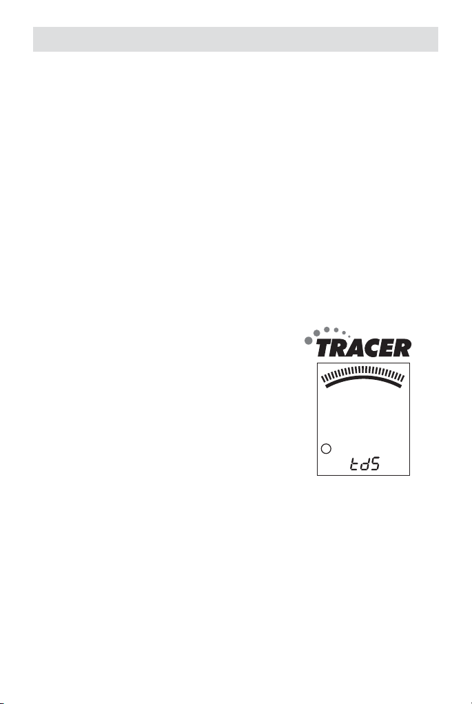
TDS Compensation Ratio
The TDS value is determined by multiplying the conductivity measurement
by a known conversion ratio factor. The meter allows the selection of a
conversion ratio factor in the range of 0.4 to 1.0. The selected ratio will
vary with application but is typically set between 0.5 and 0.7. In the salinity
mode the range is 0.4 to 0.6 auto. The stored ratio factor will briefly appear
in the lower temperature display when the meter is first turned on or when
changing the measurement function to TDS.
To change the ratio while in the TDS measurement mode
(ppm or mg/L):
1. Turn the TRACER on.
2. Press and release the CAL button twice.
The stored ratio will appear in the display.
3. Press the MODE button to change the
ratio value in steps of 0.1.
4. When the desired ratio is displayed, press
and release the CAL button to store the
value and return to the normal mode.
5. If no buttons are pressed for 5 seconds,
the meter will return to the measurement
mode.
10
0
20
0.7
L
6
Page 7

Changing the Displayed Temperature Units
To change the displayed temperature units between °C or °F:
1. With the TRACER off, press and hold the CAL button.
2. With the CAL button pressed, momentarily press the ON/OFF button.
When SELF CAL appears in the display, release the CAL button. The
TRACER will return to the operational mode with the temperature
displayed in the new units.
Data Hold
Press the MODE button to freeze the current reading. The HOLD icon will
appear. The reading will be stored. Press the MODE key to return to normal
operation.
Auto Power Off
The auto-power off feature automatically shuts the meter off 10 minutes
after the most recent button press:
Auto Power OFF Disable
1. To disable the Auto Power Off feature:
2. Turn the unit on.
3. Press CAL once (quickly).
4. Immediately and simultaneously press the MODE and ON/OFF
buttons for approximately 2 seconds, until "oFF" is briefly displayed.
To disengage this feature, turn the unit off with the ON/OFF button. The next
time the unit is powered up, Auto Power OFF mode will be engaged again.
Low Battery Indicator
The “BAT” indicator will be displayed when the batteries become weak. Refer
to the Maintenance section for battery replacement information.
7
Page 8

Measurement and Display Considerations
¬ If the unit appears to be locked (display frozen). It is possible that
the Data Hold mode has been inadvertently accessed by pressing
the MODE button. (“HOLD” will be displayed in the bottom left of the
display.) Press the MODE button again or turn the meter off and then
on.
¬ For maximum accuracy, allow sufficient time for the temperature of
the probe to reach the temperature of the sample before calibrating.
This will be indicated by a stable temperature reading on the display.
Considerations and Technique
¬ Do not touch the inner surfaces of the conductivity electrodes.
Touching the surface of the platinized electodes may damage and
reduce the life of the probe.
¬ Store the electrode in the wetting cap with the sponge moistened with
pH 4.0 buffer solution.
¬ Always rinse the electrode in deionized or distilled water between
measurements to avoid cross contamination of the sample. Double
rinsing is recommended when high accuracy is required.
¬ Periodically, accumulated salt deposits from the reference electrode
may build up in the storage cap, and should be rinsed away. These
deposits could affect measured values of low conductivity samples.
¬ When measuring low conductivity samples, extra care is recommended
in rinsing the probe to avoid contamination of the sample with electrolyte
from the pH reference electrode. This will only be a factor when
the volume of the sample. (Example: Try a 200 to 500 mL sample.)
¬ When a 20mL sample cup is usedthe electrode should not be allowed
to sit in the sample for any longer than necessary, to avoid electrolyte
leakage into the sample, raising the conductivity value.
8
Page 9

TESTING
Getting Started
¬ Remove the cap from the bottom of the Tracer to expose the pH
electrode, reference junction and conductivity electrodes.
¬ Before the first use or after storage, soak the electrode in tap water or
pH 4 buffer solution for about 10 minutes.
¬ Before first use, hold the meter by the top battery compartment
and swiftly tap the back of the meter downward into your palm (not
a hard surface). This assures that the internal electrolyte moves to
the very tip of the electrode. The electrolyte should fill the circular
junction window at the tip of the electrode.
¬ White KCL crystals may be present in the cap or on the electrode.
This is to be expected depending on the length of time in storage.
These crystals will dissolve while soaking the electrode or they can
be rinsed away with tap water.
¬ For best results calibrate with pH 7 buffer solution first, then calibrate
with the buffer solution closest to the expected pH value of the solution
or material to be tested.
¬ To preserve the pH electrode life keep the sponge in the protective cap
soaked with tap water or pH 4 buffer solution.
¬ For best results, calibrate for conductivity with a standard in the
expected range of the sample. For maximum accuracy calibrate from
low conductivity value standards to high value standards.
¬ When the meter is calibrated for conductivity, salinity or TDS the meter
must be in the conductivity mode. See page 14. For storage see page
17.
Changing Measurement Function
The meter can be set to measure pH, Conductivity, TDS, or Salinity. To
change the mode:
1. Press and hold the MODE button for 2 seconds and the display will
begin to scroll through the units.
µs (Conductivity: pH; ppm S (Salinity); ppm (TDS); mg/L (TDS
NOTE: The "HOLD" finction cannot be on when changing the
measurement function. If "HOLD" is displayed in the lower left corner
of the display, briefly press the MODE button to turn it off.
9
Page 10

2. When the desired units are displayed, release the MODE button.
NOTE: 1 part per thousand (ppt) equals 1000 parts per million (ppm).
Example: 3.1 ppt = 3,100 ppm.
3. Release the MODE key when the desired mode is displayed.
NOTE: The “HOLD” function cannot be used when changing the
measurement function. If “HOLD” is displayed in the lower left corner
of the display, briefly press the MODE button to turn it off.
MEASUREMENT PROCEDURE
Measurement
1. For small samples fill a sample cup to the 20 mL
line with the test sample. Sample depth must be
greater than or equal to 1.5 inches. pH can also
be measured by contact of the electrode tip with
a wet surface. For larger samples, like pools, go
to step 2
2. Press the ON/OFF button. (8888 and then SELF
CAL will appear in the display during the initial
diagnostics).
3. Press and hold the MODE button to scroll to the desired
measurement mode.
4. Immerse the TRACER electrode in the sample.
Make sure the electrode is completely submersed.
5. Slowly stir the sample with the TRACER to remove air
bubbles if in the Conductivity, TDS or Salinity mode.
6. If the TRACER is in the Conductivity, TDS, or Salinity
mode, the meter will automatically auto-range to the
proper range and then display
the reading. The display will flash “0000” while autoranging.
7. If the TRACER is in the pH mode, the reading will flash
until it has stabilized. This may take
several seconds depending on the buffer capacity
of the sample.
8. Rinse the electrode in distilled water. Replace the cap.
NOTE: 1 part per thousand (ppt) equals 1000 parts per million (ppm).
Example: 3.1ppt=3,100 ppm
10
Page 11

Conductivity
TDS (ppm)
TDS (mgL)
pH
Salinity
0
µS
100.9
25.0
1000
0
ppm
1000
0
790
°C
25.0
°C
mgL
790
25.0
1000
°C
2
7
790
pH
HML
78.6
12
0
Sppm
790
°F
25.0
NOTE: When measuring samples with low conductivity, thoroughly rinse the
probe with distilled or deionized water before placing it in the sample to
avoid contamination of the sample with electrolyte from the pH reference
electrode. Also increase the sample size to 200 to 500 mL to decrease the
chance of contamination. If a sample cup is used, do not allow the probe to
sit in the sample for any longer than necessary to avoid electrolyte leakage
into the sample. Leakage will raise the conductivity level.
Measuring the TDS of Soil
1. Fill a 50 mL beaker with the soil sample. Tap the beaker lightly on
a hard surface to remove trapped air. Remove excess soil from the
surface.
2. Empty the soil into a 250 mL wide-mouth flask.
3. Add 100 mL of distilled water. Stopper and shake vigorously.
4. Wait 30 minute. (Shake the flask vigorously three or four times
during this period.)
5. Filter the contents of the flask. Collect the filtrate in a beaker.
6. Rinse the electrode with distilled or deionized water to remove
impurities.
7. Press the ON/OFF button to turn the TRACER on. Make sure the
meter is in the TDS mode.
8. Immerse the electrode in the filtrate. Make sure the tip of the
electrode is completely immersed.
9. Stir the filtrate with the electrode to create a homogeneous solution.
10. Gently stir the filtrate with the electrode. Read the TDS value of the
filtrate from the display.
11. Rinse the electrode in distilled water. Replace the cap.
1000
°C
11
Page 12

Measuring the pH of Soil
1. Place a 1:1 ratio of soil and distilled water in a small beaker. For most
analyses, 20 grams of soil and 20 grams distilled water are sufficient.
2. Wait 15 minutes. Stir occasionally with a stirring rod.
3. Stir the sample. Immediately place the electrode in the sample.
4. Wait until the display stabilizes. Record the pH.
5. Rinse the electrode in distilled water. Replace cap.
NOTE: The flat surface electrode will allow for readings directly from the soil
if there is enough moisture present in the soil.
12
Page 13

Storing Readings
1. Press the MOLD button to store a reading. The
storage location number will be displayed on the
lower display, while the main display shows the
stored reading. The meter will enter the HOLD mode
and the "HOLD" indicator will appear.
2. Press the MODE button again to exit the HOLD mode
and return to normal operation.
3. If more than 25 readings are stored, previously
2
1563
L
HOLD
10
µS
stored reading (starting with number 1) will be
overwritten.
Recalling Stored Readings
1. Press the CAL button and then press the MODE button. The location
number (1 through 25) will briefly appear and then the value stored
in that location will appear. The displayed units will flash, indicating
that the storage recall mode is active.
20
4
10
2
20
15
2
1423
L
10
µS
72.3
20
°F
2. The last stored reading taken will be displayed first. To advance to
the previously stored readings, press the MODE button. The location
number is displayed first, followed by the reading stored in that
location.
3. To exit the storage mode, press the CAL button and the TRACER will
return to normal operation after displaying “End”.
Clearing Stored Memory
Turn the TRACER on. Press and hold the ON/OFF button for 4 seconds. The
display will briefly display “clr” when the memory is cleared.
13
Page 14

CALIBRATION
For the most accurate results, allow sufficient time for the temperature of
the probe to reach the temperature of the sample before calibrating. This
will be indicated by a stable temperature reading on the display.
Preparation of pH Buffers
1. Fill a sample cup with 20 mL of distilled or deionized water.
2. Add one buffer tablet:
pH 4.0 Code 3983A
pH 7.0 Code 3984A
pH 10.0 Code 3985A
3. Use the tablet crusher (0175) to crush the tablet. Stir until the tablet
has disintegrated.
NOTE: Buffers should be prepared fresh daily.
Calibration: pH (1, 2 or 3 points)
1. Place the electrode into a buffer solution (4, 7, or 10). Press and hold
the CAL button until "CAL" appears in the lower (temp.) display. When
doing a 2 or 3 point calibration, calibrate with pH 7 buffer first, then
follow with pH 4 then pH 10 buffer.
2. The TRACER automatically recognizes the solution and calibrates
itself to that value (the circled number on the LCD will match the
solution). Note that if the solution is more than 1 pH unit off from
the L (4), M (7), H (10) pH buffer, or if the electrode slope is low, the
TRACER will assume an error and abort the calibration ("End" will be
displayed, and the unit will return to measuring mode.).
3. During calibration, the pH reading flashes on the main display.
4. When calibration is complete, the TRACER automatically displays
"SA", then "End" and reurns to normal operation mode.
5. The appropriate circled indicator (L, M, or H) appears on the LCD
when a particular calibration or series of calibrations has been
completed within one power cycle. Then the TRACER is turned off,
the circled indicator configuration and the calibration data will be
retained.
6. For a two or three point calibration, repeat Steps 1-4.
7. See Reset Calibration Data to clear all calibration data from the
meter.
14
Page 15

Calibration Reminder
The “CAL” indicator will appear when the TRACER is in the pH mode and a
calibration is required. The “CAL” indicator will appear if the meter has not
been calibrated after 15 on/off cycles of the meter. Some applications may
require more frequent calibrations than others. The “CAL” indicator is only a
reminder and will not affect function in any way. The indicator will no longer
be displayed when the pH electrode is recalibrated.
RENEW Indicator
A flashing “RENEW” indicator will appear on the display to warn that
the electrode is not performing to expected specifications. If cleaning
or recalibration does not cause the RENEW indicator to disappear, the
electrode should be replaced. The RENEW indicator will appear when the pH
electrode slope falls below 70% of a nominal slope.
Calibration: Conductivity
Meter accuracy verification should be performed on a periodic basis as
needed. If calibration is required, the meter must be in the conductivity
mode to perform all calibrations for conductivity, TDS and salinity. The
meter can perform calibrations and store the data for each of the three
ranges–low, medium and high. The automatic calibration recognition
procedure will recognize conductivity standards of 84µS (Low), 1413µS
(Medium) or 12,880µS (12.88mS) (High). (See Page 6). Always calibrate in
the range closest to the expected measurement value. For salinity samples
within the range of 1.00 to 9.99 ppt salinity, calibrate with a 12,880µS
calibration standard.
1. Fill a sample cup to 20 mL line with a conductivity standard.
NOTE: The meter allows for a 1, 2, or 3 point calibration. If calibration
is done for more than one point, the lowest concentration should be
done first to obtain the best accuracy. Calibrate the ranges from low
to high
2. Press the ON/OFF button to turn the TRACER on. Insert the electrode
into the standard. Tap or stir the sample with the Tracer to dislodge
air bubbles.
3. Press and hold the CAL button for approximately 2 seconds until the
display begins to flash.
4. The meter will automatically recognize and calibrate to the
conductivity standard. The display will briefly indicate “SA” and “End”
and then return to the measurement mode.
NOTE: “SA” will not appear if the calibration fails.
15
Page 16

5. The calibration range indicator will appear on the display for each
range that is calibrated during a power on cycle.
Low Range, 84μS/cm
L
Medium Range, 1413μS/cm or 3000 ppm SaH
M
High Range, 12,88mS/cm (12,880μS/cm)
H
NOTE: Each time the calibration mode is entered all calibration range
indicators will be cleared, but only the calibration data for the currently
selected range will be replaced. The calibrations for the other two ranges
will be saved even though the indicators for those ranges are no longer
displayed. Calibration of all three ranges must be performed during one
power on period for all three calibration range indicators to be displayed.
NOTE: As with all combination pH/conductivity probes, at low conductivity
levels the flow of the pH electrolyte may affect the readings and result in
artificially high conductivity readings. To eliminate the interference, low
level conductivity or TDS measurements should be taken with a meter that
measures conductivity only.
Reset Calibration Data
Follow this procedure to clear all calibration data from the meter. Resetting
the calibration data may be necessary when new calibration solutions are
used or accuracy of measurements is in question.
1. Turn off the meter.
2. Press and hold the CAL and MODE buttons.
3. Momentarily press the ON/OFF button, as soon as they display comes
on, release all 3 buttons.
4. The display will show “dFLt rSt” (default restart) and all of the
calibration data will be erased. If “dFLt rSt” does not appear, retyr the
procedure.
5. Proceed to the calibration routine for pH and Conductivity.
16
Page 17

OPERATIONAL MATRIX
Function/
Resulting Action Power Mode Key Press Sequence
On/Off On or Off Any Momentary press of ON/OFF
Calibration On pH or Con Press & hold CAL button for 2
Store Reading On Any Momentary press of MODE
Hold Release On Hold Momentary press of MODE
Enter Memory
Retrieval
Scroll Stored
Readings
Exit Memory
Retrieval
Clear Stored
Memory
Change
Measurement
Mode
Enter CON/TDS
Ratio
Change CON/TDS
Ratio
Exit CON/TDS
Ratio
Change
Temperature
Units
On Any Measurement
Mode
On Memory Recall Momentary press of MODE
On Memory Recall Momentary press of CAL
On Any Memory Mode Press and hold the ON/OFF
On Any Press and hold the MODE
On TDS (ppm or mg/L) Press and release the CAL
On TDS (ppm or mg/L) Momentary press of MODE
On TDS (ppm or mg/L) Momentary press of CAL
Off Off Press and hold CAL button
button
seconds until CAL is displayed
button
button
Momentary press of CAL
button followed by a
momentary press of MODE
button within 4 seconds.
button. Displays last in first
out.
button
button for 4 seconds until “clr”
is displayed.
button for at least 2 seconds
Modes will scroll by until
button is released
button twice in succession
button. Each press increases
ratio by 0.1 from 0.4 to 1.0.
button.
then momentarily press ON/
OFF button. Release CAL
button after “Self Cal” is
displayed.
17
Page 18

Override Auto
Power Off
Default Reset Off N/A Simultaneously press ON/
On Any Measurement
Mode
Momentarily press CAL button
then simultaneously press
and hold ON/OFF and MODE
buttons for 2 seconds until
“oFF” is displayed.
OFF, CAL and MODE buttons
momentarily. “dFlt” will be
displayed.
MAINTENANCE
Storage
1. Rinse the electrode in distilled or deionized water.
2. Store the electrode with the cap on. Keep the sponge in the cap
soaked with tap water or pH 4 buffer solution. Do not allow sensor
to dry out. Store upright.
3. Always rinse the electrode in deionized water between
measurements to avoid cross contamination. Double rinsing is
recommended when high accuracy is required.
4. Salt deposits may build up in the storage cap and should periodically
be rinsed away. These deposits could affect measurements at low
conductivity.
Battery Replacement
1. Twist off the battery compartment cap.
2. Hold the battery housing in place with one finger. Remove the battery
carrier by pulling on the small tabs.
3. Replace the four CR2032 batteries. Observe polarity.
4. Replace the battery compartment cap.
18
Page 19

Never dispose of used batteries or rechargeable batteries in household
waste. As consumers, users are legally required to take used batteries
to appropriate collection sites, the retail store where the batteries were
purchased, or wherever batteries are sold.
Disposal: Do not dispose of this instrument in household
waste. The user is obligated to take end-of-life devices to a
designated collection point for the disposal of electrical and
electronic equipment.
ELectrode Care
1. Always rinse the electrode in distilled or deioized water between
measurements to avoid cross-contamination of the samples. Double
rinsing is recommended when high accuracy is required.
2. Do not touch the electrodes. Touching the surface of the platinized
electrodes may damage and reduce the life of the electrodes.
Replacing the Electrode
The TRACER is shipped with an electrode attached. Electrode life is limited
and is dependant on the frequency of use and care. If the electrode needs to
be replaced, follow these steps for removing and connecting electrodes.
1. Turn meter off.
2. To remove the electrode, turn the collar counter-clockwise and
remove it.
3. Gently rock the electrode from side to side, pulling it downwards, until
it disconnects from the meter.
4. To attach an electrode, carefully plug the electrode into the meter
socket. Note that the electrode connector is keyed to ensure a proper
connection.
CAUTION: Take case to align pins carefully. Bent or broken ins will
cause the meter to malfunction.
5. Tighten the electrode collar firmly enough to make a good seal. A
rubber gasket will seal the electrode with the meter.
19
Page 20

Electrode Cleaning Recommendations
Do not soak the electrode in the solutions for longer than the recommended
length of time. To do so may cause a reference potential shift which will
cause degradation in performance or failure. When cleaning the electrode,
take care not to scratch or damage the sensing surface or the platinized
electrode surfaces.
Contaminant Cleaning Solution Procedure
Water soluble Deionized water Soak or scrub with a soft brush. Recondition
Grease and oil Warm water
Heavy grease Alcohol Soak for a maximum of 5minutes. Scrub with
Lime and
hydroxide
coatings
and household
detergent
10% Acetic acid Soak until coating dissolves, maximum 5
in pH 4 or 7 buffer for 1 hour.
Soak or scrub with a soft brush, maximum
10 minutes. Rinse thoroughly with DI water.
Recondition in pH 4 or 7 buffer for 1 hour.
a soft brush. Rinse thoroughly with DI water.
Recondition in pH 4 or 7 buffer for 1 hour.
minutes. Rinse thoroughly with DI water.
Recondition in pH 4 or 7 buffer for 1 hour.
20
Page 21

TROUBLESHOOTING
Problem Possible Cause Action
Reading is frozen Unit is in "HOLD" mode Press MODE button to exit "HOLD"
"BAT" message Batteries are low Replace batteries.
Meter will not
calibrate in pH
Meter will not
calibrate in
conductivity
mode
Unit will not turn onBatteries low or dead Replace batteries.
“RENEW”
message
Unit will not
respond to any
key presses
Low pH slope Replace electrode.
Clogged or contaminated
reference junction
Damaged or worn sensing
membrane
Contaminated pH buffers Use fresh buffers.
Trapped air bubbles Tap or stir to release air bubbles.
Dirty probe Clean conductivity probe.
Damaged conductivity
probe
Contaminated conductivity
standards
Battery installed with
incorrect polarity
pH sensor needs
recalibration
pH sensor slope has fallen
below acceptable limits
Internal fault Perform hard reboot: Remove
mode.
Clean junction.
See cleaning instructions.
Replace electrode.
See cleaning instructions.
Replace electrode.
Use fresh standards.
Replace batteries, observe polarity.
Recalibrate unit.
Use fresh buffers.
Replace electrode.
batteries, hold ON/OFF switch down
for 5 seconds, replace batteries.
21
Page 22

WARRANTY
LaMotte Company warrants this instrument to be free of defects in parts
and workmanship for 1 year from the date of shipment and warrants this
probe be free of defects in parts and workmanship for 6 months from the
date of shipment. If it should become necessary to return the instrument for
service during or beyond the warranty period, contact our Technical Service
Department at 1-800-344-3100 for a return authorization number or visit
www.lamotte.com for troubleshooting help. The sender is responsible for
shipping charges, freight, insurance and proper packaging to prevent damage
in transit. This warranty does not apply to defects resulting from action of
the user such as misuse, improper wiring, operation outside of specification,
improper maintenance or repair, or unauthorized modification. LaMotte
Company specifically disclaims any implied warranties or merchantability
or fitness for a specific purpose and will not be liable for any direct, indirect,
incidental or consequential damages. LaMotte Company’s total liability is
limited to repair or replacement of the product. The warranty set forth above
is inclusive and no other warranty, whether written or oral, is expressed or
implied.
To register your meter with the LaMotte Service Department,
go to www.lamotte.com
and choose SUPPORT on the top navigation bar.
22
Page 23

INTRODUCTION
Félicitations pour votre acquisition du mesureur de TRACER PockeTester
Avec la technologie dynamique à constante de cellule électrolytique du
TRACER, il est possible de mesurer une large gamme de Conductivité, TDS
et Salinité avec la même électrode. Cet appareil peut être utilisé pendant
plusieurs années s’il est manié avec précaution.
AVERTISSEMENT ! Ce kit contient des
produits chimiques qui peuvent être nocifs s’ils sont utilisés de façon impropre.
Lisez avec attention les avertissements
sur chaque récipient. Ce produit n’est
pas destiné à être utilisé par des enfants,
sauf sous la surveillance d’un adulte.
23
Page 24

CARACTÉRISTIQUES TECHNIQUES
Affichage LCD avec 2000 impulsions d’affichage et diagramme
Gamme pH 0,00 à 14,00
Précision pH ±0,01 pH typique
Gamme pH ATC 0°C à 90°C (32°F à 194°F)
Jonction de Référence de pH Gel permanent, non re-remplissable
Gammes de conductivité 0 à 199,9μS/cm
Gammes TDS
(Ratio variable)
Gamme de salinité 0 à 99.9ppm
Taux TDS réglable de 0,4 à 1,0
Taux de Salinité 0,4 à 0,6 automatique
ATC de Conductivité 2,0% par °C
Gamme de température 0,0°C à 65,0°C (32,0°F à 149°F)
Résolution de Température 0,1 à 99,9, 1 >100
Précision de la Température ±1°C; -16,78°C (de 0 à 50°C; 32 à 50,00°F)
Gamme ATC de Conductivité 0,0°C à 60,0°C (32,0°F à 140°F)
Précision Conductivité : ±2% déviation maximale
Mémoire de mesure 25 lecture marquées (numérotées)
Indication piles faibles ‘BAT’ apparaît sur l’écran
Marche/Arrêt Quatre (4) piles lithium ion CR2032
Arrêt automatique Après 10 minutes (remplacement disponible)
Conditions de fonctionnement -5°C à 50°C (23°F à 122°F)
Dimensions 40 x 200 x 40 mm (1,6 x 7,9 x 1,6”)
Poids 93 g (3,55 g)
NOTE: 1 part per thousand (ppt) equals 1000 parts per million (ppm). Example: 3.1ppt=3,100 ppm
en barres
200 à 1999μS/cm
2,00 à 19,99mS/cm
0 à 99.9ppm ou mg/L
100 à 999ppm ou mg/L
1.00 à 9.99ppt ou g/L
100 à 999ppm
1.00 à 9.99ppt
±3°C; -14,78°C (de 50 à 65°C; 122 à 149,0°F)
TDS: ±2% déviation maximale
Salinité : ±2% déviation maximale
24
Page 25

CONTENU
Kit TRACER PockeTester pH/CON Code 1766
Comprend : Un récipient d’échantillon avec bouchon †
Un broyeur de pastille
Des pastilles tampon pH 4,0, 7,0 et 10,0 †
Une solution d’étalon de conductivité, 12 880 µS
†Produit non vendu dans cette quantité. Voir ci-dessous.
Code 0175
Code 6317-G
PIÈCES ET ACCESSOIRES
Électrode de rechange pH/TDS/SELS Code 1755
Support lesté avec récipients d’échantillon (5) Code 1746
Récipients d’échantillon avec bouchons (24) Code 1745
Pastilles tampon mini pH 4,0 (100 Code 3983A-J
Pastilles tampon mini pH 7,0 (100) Code 3984A-J
Pastilles tampon mini pH 10,0 (100) Code 3985A-J
Solution d’étalon de conductivité, 84 µS, 30 mL, 500 mL Code 6312-G, L
Solution d’étalon de conductivité, 1413 µS, 30 mL, 500 mL Code 6354-G, L
Solution d’étalon de conductivité, 12 880 µS, 30 mL, 500 mL Code 6317-G, L
*AVERTISSEMENT : Les réactifs signalés par une astérisque * sont considérés comme
représentant des dangers potentiels pour la santé. Pour afficher ou imprimer les fiches de
données de sécurité (FDS) de ces réactifs, accédez à www.lamotte.com. Cherchez le code
à quatre chiffres du réactif indiqué sur l’étiquette du réactif, dans la liste du contenu ou
dans les procédures d’analyse. Ignorez toute lettre précédant ou suivant le code à quatre
chiffres.
Par exemple, si le code est 4450WT-H, tenez compte uniquement de 4450. Pour obtenir
une version imprimée, contactez LaMotte par courriel, téléphone ou fax.
En cas d’urgence, des informations pour tous les réactifs LaMotte sont disponibles auprès
de Chem-Tel : (US 1-800-255-3924) (appel international, en PCV, 813-248-0585).
Pour commander à nouveau des réactifs ou des composants de kit d’analyse séparément,
utiliser les numéros de code indiqués.
25
Page 26

DESCRIPTION DE L’APPAREIL
Panneau Avant :
1. Compartiment à piles
2. Ecran LCD
3. Bouton MODE (change le mode,
Maintient et mémorise les données)
4. Bouton CAL (Calibrage, changement
des unités de température et rappel
des données).
5. Bouton ON / OFF (Marche/Arrêt)
6. Bague de l’Electrode
7. Electrode de pH/Conductivité
(Remarque: le capuchon de l’électrode
n’est pas montré)
TRACER Ecran LCD
1. Affichage à diagramme en barres
2. Unités de mesure
3. Affichage principal
4. Calibrage de gamme et indicateurs
de pile
5. Affichage de la température
6. Indicateur "Renew"
7. 6. Indicateur des mesures gêlées
26
1
2
6
7
5
10
7
0
0
m
t
mg/L
S
pp
2
µ
m
88.88
BAT pH
HML
RENEW
-8.8.8
HOLD
10
20
12
3
4
°C
5
°F
Page 27

FONCTIONNEMENT DE BASE
Mettre en marche le TRACER
Le mesureur TRACER requiert quatre (4) piles litium ion CR2032 (incluses).
Sii le niveau des piles est faible, le symbole ‘BAT’ apparaît sur l’écran.
Appuyez sur le bouton ON/OFF pour allumer ou éteindre le TRACER. La
fonction mise hors tension automatique éteint automatiquement le TRACER
après 10 minutes d’inactivité, pour préserver la vie de la pile.
Taux de Compensation de TDS
La valeur TDS est déterminée en multipliant une lecture de conductivité par
un facteur de taux connu. Le mesureur permet de sélectionner un taux de
conversion de 0,4 à 1,0. Ce taux varie en fonction de l’application, mais il est
généralement réglé entre 0,5 et 0,7.
Remarque : Le taux enregistré apparaîtra brièvement sur l’affichage de
température inférieur lorsque le mesureur est allumé pour la première fois
ou lorsqu’on change vers la mesure de TDS.
Remarque : En mode Salinité, le taux est 0,4 à 0,6 automatique.
Pour changer le taux, en étant en mode mesure de TDS (ppm ou mg/l) :
1. Appuyez et relâchez le bouton CAL deux
fois de suite. Le taux mémorisé apparaîtra
sur l’écran.
2. Appuyez sur le bouton MODE pour
augmenter la valeur du taux par paliers de
0,1.
3. Lorsque le taux souhaité est affiché,
appuyez et relâchez le bouton CAL pour
mémoriser la valeur et retourner au mode
normal.
4. Si aucun bouton n’est pressé pendant 5
secondes, le mesureur retourne au mode de mesure.
10
0
20
0.7
L
Changer les Unités de Température
Pour changer les unités de la température affichée (ºC ou ºF) :
1. Avec l’appareil éteint, appuyez et maintenez enfoncé le bouton CAL.
2. Avec le bouton CAL appuyé momentanément, appuyez sur le bouton
ON/OFF. Lorsque “SELF CAL” apparaît sur l’écran, relâchez le bouton
CAL. L’appareil s’allumera avec l’affichage de la nouvelle unité de
température.
27
Page 28

Mode Maintenance de Données
Appuyez sur le bouton MODE pour maintenir (geler) une lecture sur l’écran.
Le mesureur entrera en mode HOLD, et l’indicateur HOLD apparaîtra.
Remarque : Ceci mémorise également la valeur mesurée.
Appuyez de nouveau sur le bouton MODE/HOLD pour revenir au
fonctionnement normal.
Extinction automatique
La fonction extinction automatique éteint automatiquement le mesureur 10
minutes après la dernière pression de bouton.
Désactiver l’arrêt automatique
Pour désactiver la fonction de l’éxtinction automatique:
1. Allumez l’appareil.
2. Appuyez une fois (brièvement) sur CAL.
3. Appuyez immédiatement et simultanément sur les boutons MODE et
ON/OFF pendant environ 2 secondes, jusqu’à l’affichage “OFF”.
Pour désactiver cette fonction, éteignez l’unité avec le bouton ON/OFF.
La prochaine fois que vous allumez l’appareil, le mode de l’extinction
automatique sera automatiquement activé.
Indication Piles Faibles
Lorsque les piles sont faibles, l’icône ‘BAT’ apparaît sur l’écran. Reportezvous à la section Maintenance pour savoir comment remplacer les piles
Considérations sur la Mesure et l’Affichage
.
¬ Si l’appareil semble bloqué (écran gelé). Il est possible que le mode
Maintenance de Données ait été activé involontairement en appuyant
sur le bouton MODE. (“HOLD” sera affiché en bas à gauche sur l’écran.)
Appuyez tout simplement de nouveau sur le bouton MODE ou éteignez
et rallumez le mesurer.
¬ Pour une précision maximale, attendez un peu avant le calibrage
pour que la température de la sonde atteigne la température de
l’échantillon. Ceci sera indiqué par une tempéraure stable sur l’écran.
28
Page 29

Considérations et Techniques
¬ Ne touchez pas les surfaces intérieures de la sonde de conductivité.
Si vous touchez la surface des électrodes platinées, cela risque
d’endommager la sonde et de réduire sa durée de vie.
¬ Conserver l’électrode dans son capuchon avec l’éponge humidifié d’une
solution de tampon pH 4.0.
¬ Rincez toujours l’électrode dans de l’eau déminéralisée entre les
mesures, afin de ne pas mélanger la contamination de l’échantillon. Un
rinçage double est recommandé lorsqu’une plus grande précision est
exigée.
¬ Régulièrement, les dépôts de sel accumulés de l’électrode de référence
peuvent se former dans le capuchon de stockage et doivent être rinçés.
Ces dépôts pourraient avoir une influence sur les valeurs mesurées sur
des échantillons de basse conductivité.
¬ En mesurant des échantillons de basse conductivité, une attention
particulière est recommandée en rinçant la sonde pour éviter la
contamination de l’échantillon avec de l’électrolyte de l’électrode
pH de référence. Ceci est uniquement un facteur à considérer lors
de la mesure en basse gamme et peut être minimisé davantage
en augmentant le volume de l’échantillon. (Exemple : Essayez un
échantillon de 200 à 500 mL.)
¬ Si la tasse d’échantillon de 20ml va être utilisée, alors l’électrode ne
doit pas être logée dans l’échantillon plus longtemps que nécessaire,
pour éviter qu'une fuite pH d’électrolyte contamine l’échantillon et
augmente ainsi la valeur de la conductivité.
DÉMARRAGE
¬ Retirez le couvercle situé au bas du ExStik pour exposer l’électrode pH,
la jonction de référence et les électrodes de conductivité.
¬ Avant la première utilisation ou après le rangement, baignez l’électrode
sous l’eau du robinet ou une solution à tampon pH 4 pendant environ
10 minutes.
¬ Avant toute utilisation, maintenez l’instrument par le haut, au
niveau du compartiment des piles, et tapotez sèchement l’arrière de
l’instrument dans la paume de votre main (non sur une surface dure).
Ainsi, l’électrolyte interne se déplace tout au bout de l’électrode.
L’électrolyte doit remplir la fenêtre ronde de jonction au bout de
l’électrode.
¬ Des cristaux blanc chlorure de potassium peuvent se trouver sur le
couvercle ou sur l’électrode. Cela dépendra de la durée du stockage.
Ces cristaux se dissoudront en baignant l’électrode ou par rinçage sous
l’eau du robinet.
29
Page 30

¬ Pour obtenir de meilleurs résultats, calibrez d’abord avec une solution
tampon à pH 7, puis calibrez avec la solution tampon plus proche de la
valeur pH attendue de la solution ou matériel à tester.
¬ Pour préserver la durée de vie de l’électrode pH, maintenez l’éponge
dans le couvercle protecteur sous l’eau du robinet ou une solution
tampon à pH 4.
¬ Pour de meilleures résultats, calibrez pour la conductivité avec un
standard dans la zone attendue de l’échantillon. Pour une plus grande
précision, calibrez de faible conductivité à conductivité élevée.
¬ Lorsque vous étalonnez l’instrument pour la conductivité, la salinité
ou le TDS, réglez-le sur le mode conductivité. Voir page 33. Pour le
stockage, voir page 38.
Changer la Fonction des Mesures
Le mesureur peut être réglé pour mesurer pH, la Conductivité, la TDS ou la
Salinité.
Pour changer le mode :
1. Appuyez sur le bouton MODE/HOLD pendant 2 secondes et l’écran
commencera à faire défiler les unités.
μS (Conductivité); pH; ppm S (Salinité); ppm (TDS); mg/l (TDS);
Remarque : La fonction “HOLD” ne peut pas être en marche lorsque
vous changez la fonction de mesure. Si “HOLD” s’affiche au coin
inférieur gauche de l’écran, appuyez brièvement sur le bouton MODE
pour l’éteindre.
2. 2. Lorsque les unités souhaitées s’affichent, relâchez le bouton
MODE.
30
Page 31

PROCÉDURE DE MESURE
Mesure
1. Pour de petits échantillons, remplissez un
récipient d’échantillon avec l’échantillon
à analyser jusqu’à la ligne des 20 mL. La
profondeur de l’échantillon doit être supérieure
ou égale à 1,5 pouces. Vous pouvez également
mesurer le pH en mettant en contact le bout
de l’électrode avec une surface humide. Pour
des échantillons plus volumineux, comme des
piscines, passez à l’étape 2.
2. Appuyez sur le bouton ON/OFF. (8888 puis
SELF CAL s’affiche à l’écran pendant les diagnostics
initiaux.)
3. Appuyez sur le bouton MODE et maintenez-le enfoncé
pour atteindre le mode de mesure désiré.
4. Immergez l’électrode du TRACER dans l’échantillon.
Assurez-vous que l’électrode est complètement
immergée.
5. Mélangez délicatement l’échantillon avec le TRACER
pour éliminer toute bulle d’air, si l’instrument est en
mode conductivité, TDS ou salinité.
6. Si le TRACER est en mode conductivité, TDS ou
salinité, il sélectionnera automatiquement la plage
appropriée, puis affichera le résultat. L’affichage
clignote et indique « 0000 » lorsque la sélection
automatique de plage est en cours.
7. Si le TRACER est en mode pH, le résultat clignote jusqu’à ce qu’il
se stabilise. Cela peut durer plusieurs secondes selon la capacité
tampon de l’échantillon.
8. Rincez l’électrode à l’eau distillée. Remettez le bouchon.
REMARQUE : 1 ppt (partie par centaine) est égale à 1000 ppm (parties par
million). Exemple : 3,1 ppt = 3100 ppm
Conductivity
0
µS
100.9
25.0
TDS (ppm)
1000
0
ppm
790
°C
25.0
TDS (mgL)
1000
0
mgL
1000
790
°C
25.0
pH
7
2
790
pH
HML
°C
78.6
Salinity
12
0
1000
Sppm
790
°C
°F
25.0
31
Page 32

Remarque: lorsque vous mesurez des échantillons à faible conductivité,
rincez abondamment la sonde avec de l'eau distillée ou désionisée avant de
la placer dans l'échantillon afin d'éviter toute contamination de l'échantillon
par l'électrolyte de l'électrode de référence du pH. Augmentez également
la taille de l'échantillon à 200 à 500 ml pour diminuer les risques de
contamination. Si un échantillon de tasse est utilisé, ne pas laisser la sonde
s'asseoir dans l'échantillon plus longtemps que nécessaire pour éviter les
fuites d'électrolyte dans l'échantillon. La fuite augmentera le niveau de
conductivité.
Mesure du TDS du sol
1. Remplissez un bécher de 50 mL avec l’échantillon de sol. Tapotez
légèrement le bécher sur une surface dure pour évacuer l’air. Enlevez
l’excédent de terre à la surface.
2. Transvasez la terre dans un flacon à col large de 250 mL.
3. Ajoutez 100 mL d’eau distillée. Fermez le flacon et agitez-le
vigoureusement.
4. Patientez 30 minutes. (Agitez le flacon vigoureusement trois ou
quatre fois pendant ce temps.)
5. Filtrez le contenu du flacon. Recueillez le filtrat dans un bécher.
6. Rincez l’électrode à l’eau distillée ou désionisée pour enlever toutes
les impuretés.
7. Appuyez sur le bouton ON/OFF pour allumer le TRACER. Vérifiez que
l’instrument est en mode TDS.
8. Immergez l’électrode dans le filtrat. Assurez-vous que le bout de
l’électrode est complètement immergé.
9. Mélangez le filtrat avec l’électrode pour rendre la solution homogène.
10. Mélangez délicatement le filtrat avec l’électrode. Lisez la valeur TDS
du filtrat à l’écran.
11. Rincez l’électrode à l’eau distillée. Remettez le bouchon.
32
Page 33

Mesure du pH du sol
1. Mettez de la terre et de l’eau distillée dans un petit bécher en
proportion 1:1. Pour la plupart des analyses, 20 grammes de terre et
20 grammes d’eau distillée sont suffisants.
2. Patientez 15 minutes. Mélangez de temps en temps à l’aide d’un
bâtonnet agitateur.
3. Mélangez l’échantillon. Placez immédiatement l’électrode dans
l’échantillon.
4. Patientez jusqu’à ce que l’affichage se stabilise. Enregistrez le pH.
5. Rincez l’électrode à l’eau distillée. Remettez le bouchon.
REMARQUE : La surface plane de l’électrode permet de mesurer le pH
directement à partir du sol si ce dernier est suffisamment humide.
Mémoriser les Lectures
1. Appuyez sur le bouton MODE pour mémoriser une
lecture. Le numéro de localisation de mémorisation
sera affiché sur l’écran inférieur suivi de la lecture
mémorisée sur l'écran principal. Le mesureur entrera
en mode HOLD, et l’indicateur HOLD apparaîtra.
2. Appuyez à nouveau sur le bouton MODE pour quitter
le mode HOLD et retourner au fonctionnement
normal.
3. Si plus de 25 lectures sont mémorisées, les lectures
mémorisées précédemment (en commençant par le numéro 1)
seront effacées.
2
1563
L
HOLD
10
µS
20
4
Rappel de Lectures Mémorisées
1. Appuyez sur le bouton CAL puis appuyez sur le bouton MODE. Un
numéro de localisation (de 1 à 25) apparaîtra brièvement, puis la
valeur mémorisée à cette place s’affichera. Les unités affichées
clignoteront, indiquant que le mode rappel de mémoire est actif.
10
2
20
15
33
2
1423
L
10
µS
72.3
20
°F
Page 34

2. La dernière lecture mémorisée sera affichée en premier. Appuyez et
relâchez le bouton MODE pour faire défiler les lectures mémorisées
une par une. Le numéro de localisation est affiché en premier, suivi
de la lecture mémorisée à cette place.
3. Pour quitter le mode mémoire, appuyez sur le bouton CAL, et le
mesureur retournera au fonctionnement normal, après avoir affiché
‘End’.
Effacer le Contenu de la Mémoire
Avec l’appareil allumé, appuyez et maintenez enfoncé le bouton ON/OFF
pendant 4 secondes. “clr” s’affichera brièvement lorsque la mémoire sera
effacée.
CALIBRAGE
Pour une précision maximale, attendez un peu avant le calibrage pour que la
température de la sonde atteigne la température de l’échantillon. Ceci sera
indiqué par une tempéraure stable sur l’écran.
Préparation des solutions tampon
1. Remplissez un récipient d’échantillon avec 20 mL d’eau distillée ou
désionisée.
2. Ajoutez une pastille tampon :
pH 4,0 Code 3983A
pH 7,0 Code 3984A
pH 10,0 Code 3985A
3. Utilisez le broyeur (0175) pour triturer la pastille. Mélangez jusqu’à ce
que la pastille se soit dissoute.
REMARQUE : Les solutions tampon doivent être fraîches et préparées
quotidiennement.
Calibrage - pH (1, 2, ou 3 points)
1. Placez l’électrode dans une solution tampon (4, 7 ou 10). Appuyé et
maintenez enfonçé le bouton CAL, jusqu’à ce que “CAL” apparaisse
sur l‘affichage inférieur (temp.). Lorsque vous effectuez un calibrage
à 2 ou 3 oints, calibrez d’abord le tampon à pH 7, puis passez au pH 4
et enfin au pH 10.
2. TRACER reconnaît automatiquement la solution et se calibre
sur cette valeur (le numéro encerclé sur l’écran correspond à la
solution). Notez que si la solution est supérieure à 1 unité de pH
34
Page 35

du tampon L (4), M (7), ou H (10) ou si la courbe de l’électrode est
basse, TRACER supposera une erreur et abondonnera le calibrage
(‘End’ s’affiche et l'appareil retourne au mode de mesure).
3. Pendant le calibrage, la lecture de pH clignote sur l’affichage
principal.
4. Lorsque le calibrage est terminé, TRACER affiche automatiquement «
SA » et ‘End’ et retourne au mode de fonctionnement normal.
5. L’indicateur encerclé approprié (L, M ou H) apparaît sur l’écran
lorsqu’un calibrage particulier ou une série de calibrage a été
effectué. Lorsque TRACER est éteint, la configuration de l’indicateur
encerclé et les données de calibrage seront mémorisées.
6. Pour un calibrage à deux ou trois points, répétez les étapes 1 à 4.
7. Voir les données d'étalonnage à zéro pour effacer toutes les données
d'étalonnage du compteur.
Rappel concernant l’étalonnage
L’indicateur « CAL » apparaît lorsque le TRACER est en mode pH et qu’un
étalonnage est nécessaire. L’indicateur « CAL » apparaît si l’instrument
n’a pas été étalonné au bout de 15 cycles de marche/arrêt. Certaines
applications exigent des étalonnages plus fréquents. L’indicateur « CAL »
est uniquement un rappel et n’aura aucun impact sur le fonctionnement de
l’instrument. L’indicateur disparaît lorsque l’électrode pH est ré-étalonnée.
Affichage RENEW
Un avertissement ‘RENEW’ clignotant indique que la sonde ne fonctionne
pas dans le cadre des spécifications prévu. Si le nettoyage ou le recalibrage
ne font pas disparaître l’icône RENEW, remplacez la sonde (voir accessoires
optionnels en dernière page de ce manuel). L’icône RENEW disparaît car
la pente de l’électrode pH est tombée au-dessous de 70% de la pente
nominale.
Étalonnage : conductivité
Vérifiez régulièrement la précision de l’instrument, selon vos besoins.
Si vous devez étalonner l’instrument, vous devez le régler sur le
mode conductivité pour pouvoir effectuer tous les étalonnages pour
la conductivité, le TDS et la salinité. L’instrument peut réaliser des
étalonnages et enregistrer les données pour chacune des trois plages
(inférieure, moyenne et supérieure). La procédure de reconnaissance
d’étalonnage automatique reconnaît les solutions d’étalon de conductivité
de 84 µS (plage inférieure), 1413 µS (plage moyenne) ou 12 880 µS (12,88
mS) (plage supérieure). (Voir page 6.) Étalonnez toujours l’instrument dans
35
Page 36

la plage la plus proche possible de la valeur de mesure attendue. Pour les
échantillons de salinité compris dans la plage allant de 1,00 à 9,99 ppt de
salinité, étalonnez l’instrument avec une solution d’étalon de 12 880 µS.
1. Remplissez un récipient d’échantillon avec une solution d’étalon de
conductivité jusqu’à la ligne des 20 mL.
REMARQUE : L’instrument permet un étalonnage à 1, 2 ou 3 points.
Si vous réalisez un étalonnage pour plus d’un point, commencez par
la concentration la plus faible afin d’obtenir la meilleure précision
possible. Étalonnez les plages en commençant par la plage inférieure
et en terminant par la plage supérieure.
2. Appuyez sur le bouton ON/OFF pour allumer le TRACER. Insérez
l’électrode dans la solution d’étalon. Tapotez ou mélangez
délicatement l’échantillon avec le Tracer pour déloger toute bulle
d’air.
3. Appuyez sur le bouton CAL et maintenez-le enfoncé pendant 2
secondes environ jusqu’à ce que l’affichage se mette à clignoter.
4. L’instrument reconnaît et étalonne automatiquement la solution
d’étalon de conductivité. L’affichage indique brièvement « SA » et «
END », puis repasse en mode de mesure.
REMARQUE : « SA » ne s’affiche pas si l’étalonnage n’a pas
fonctionné.
5. L’indicateur de plage d’étalonnage apparaît à l’écran pour chaque
plage étalonnée pendant un cycle de fonctionnement.
Gamme basse, 84μS/cm
L
Gamme moyenne, 1413μS/cm or 3000 ppm SaH
M
Gamme haute, 12,88mS/cm (12,880μS/cm)
H
REMARQUE : À chaque fois que vous passez en mode d’étalonnage, tous
36
Page 37

les indicateurs de plage d’étalonnage sont effacés, mais uniquement les
données d’étalonnage de la plage en cours de sélection seront remplacées.
Les étalonnages des deux autres plages seront enregistrés même si les
indicateurs de ces plages ne sont plus affichés. L’étalonnage des trois
plages doit être effectué pendant un même cycle de fonctionnement pour
que chacun des indicateurs des trois plages d’étalonnage s’affiche.
REMARQUE : De même que pour toutes les sondes de pH/conductivité,
en cas de niveaux de conductivité faibles, le flux de l’électrolyte pH peut
fausser les résultats et donner des résultats de conductivité artificiellement
élevée. Pour éliminer cette interférence, réalisez les mesures à faible niveau
de conductivité ou de TDS avec un instrument mesurant uniquement la
conductivité.
Réinitialiser les données d’étalonnage
Suivre cette procédure pour effacer toutes les données d’étalonnage du
compteur. Réinitialiser les données d’étalonnage peut être nécessaire
lorsque de nouvelles solutions d’étalonnage sont utilisés ou de l’exactitude
des mesures est en question.
1. Désactiver le compteur.
2. Appuyez et maintenez enfoncée la touche Cal/Rappel/Mode et
maintenez les boutons.
3. Appuyer brièvement sur le bouton On/Off, dès que l’écran s’allume,
relâchez tous les boutons 3.
4. L’affichage indique “dFLt rSt” (par défaut) et toutes les données
d’étalonnage seront effacées. Si “dFLt rSt” n’apparaît pas,
recommencez la procédure.
5. Passez à la routine d’étalonnage pour pH et Conductivité
37
Page 38

MATRICE D’OPÉRATION
Fonction/Action
résultante
On/Off On ou Off N’importe
Calibrage On Conductivité Appuyez et maintenez appuyé le
Mémorise les
lectures
Hold Release On En mode Hold Appuyer momentanément sur le
Saisir Extrait de la
Mémoire
Faire défiler les
Lectures
Quitter Extrait de
Mémoire
Effacer le Contenu
de la Mémoire
Changer le Mode de
Mesure
Saisir taux Cond/
TDS
Changer taux Cond/
TDS
Quitter taux Cond/
TDS
Statut de
Marche
On N’importe
On N’importe
On Mémorisées
On Rappel de
On N’importe
On N’importe
On TDS (ppm ou
On Taux TDS Appuyer momentanément sur le
On Taux TDS Appuyer momentanément sur le
Réglage
de mode
lequel
lequel
quel Mode de
Mesure
On Rappel de
Mémoire
Mémoire
quel Mode de
Mesure
lequel
mg/l)
Séquence de boutons
nécessaire
Appuyer momentanément sur le
bouton ON/OFF
bouton CAL pendant 2 seondes,
jusqu’à l’affichage de la fonction
CAL.
N’importe quel Mode de Mesure
Appuyer momentanément sur le
bouton MODE
bouton MODE
Appuyer momentanément
sur le bouton CAL puis
momentanément sur MODE
(pendant 4 secondes).
Appuyer momentanément sur le
bouton MODE (Affiche d’abord la
dernière lecture)
Appuyer momentanément sur le
bouton CAL
Appuyer et maintenir enfoncé
le bouton ON/OFF pendant 4
secondes jusqu’à l’affichage
“clr”
Appuyer et maintenir enfoncé
le bouton MODE pendant au
moins 2 secondes (les modes
défileront jusqu’à ce que le
bouton soit relâché)
Appuyer et relâcher le bouton
CAL deux fois de suite
bouton MODE (chaque pression
augmente le taux de 0,1, et les
cycles de valeur de 0,4 à 1,0)
bouton CAL
38
Page 39

Changer les Unités
de Température
Désactiver
Extinction
automatique
Remise à zéro Off N/D Appuyez et maintenez enfonçé
OFF Off n/a (mode
off)
On N’importe
lequel Mode de
Mesure
Appuyer et maintenir enfoncé
le bouton CAL, puis appuyer
momentanément sur ON/OFF.
Relâcher le bouton CAL après
que ‘SELF CAL’ s’allume
Appuyer momentanément
sur Cal puis simultanément
appuyer et maintenir enfoncé les
boutons ON/OFF et MODE/HOLD
pendant 2 secondes jusqu’à
l’affichage de « oFF »
simultanément le bouton ON/
OFF, CAL/RECALL et MODE/
HOLD. “dFLt” s’affiche.
ENTRETIEN
Stockage
1. Rincez l’électrode à l’eau distillée ou désionisée.
2. Stockez l’électrode avec son bouchon. Gardez l’éponge du bouchon
imbibée d’eau du robinet ou de solution tampon pH 4. Ne laissez pas
le capteur sécher. Stockez l’instrument à la verticale.
3. Rincez toujours l’électrode avec de l’eau désionisée entre chaque
mesure pour éviter la contamination croisée. Rincez deux fois si vous
avez besoin de résultats très précis.
4. Des dépôts de sel peuvent se former dans le bouchon de stockage. Ils
doivent être éliminés. Pour ce faire, rincez régulièrement le bouchon.
Ces dépôts peuvent fausser les mesures en cas de conductivité
faible.
Remplacement des piles
1. Dévissez le couvercle du compartiment des piles
2. Maintenez le compartiment des piles avec un doigt, retirez le support
des piles en tirant sur les deux languettes.
3. Reinsérez les quatre (4) piles CR2032 en respectant la polarité.
4. Refermez le compartiment des piles
39
Page 40

Ne jetez jamais les piles ou batteries rechargeables dans
les déchets ménagers. En tant que consommateurs, les
utilisateurs sont légalement tenus de prendre les au lieu de
collecte, le magasin de détail où les batteries ont été achetés,
ou partout où les batteries sont vendues.
Élimination : ne pas disposer de cet instrument dans les déchets ménagers.
L’utilisateur s’engage à retirer de la périphériques à un point de collecte pour
l’élimination des équipements électriques et électroniques.
Remplacement de l’électrode
1. Dévissez et enlevez le collier de l’électrode. Tournez le collier dans le
sens contraire des aiguilles d’une montre.
2. Faites osciller délicatement l’électrode d’un côté puis de l’autre
tout en la tirant doucement de son logement, jusqu’à ce qu’elle s’en
détache.
3. Pour fixer une électrode, faites correspondre les encoches et
insérez délicatement l’électrode dans son logement. PRUDENCE :
Veillez à bien aligner les broches. Les broches tordues ou cassées
empêcheront l’instrument de fonctionner correctement.
4. Vissez fermement le collier de l’électrode afin de bien le sceller avec
le joint en caoutchouc qui se trouve entre l’électrode et l’instrument.
40
Page 41

Conseils de nettoyage de l’électrode
Ne faites pas tremper l’électrode dans des solutions au-delà du temps
recommandé. Vous risquez de déplacer le potentiel de référence ce qui
réduirait la performance ou entraînerait un dysfonctionnement. Lorsque
vous nettoyez la sonde, veillez à ne pas gratter ni endommager les surfaces
platine de l’électrode.
Contaminant Solution Netoyyante Instructions
Substances solubles
dans l’eau
Graisse et Huile Eau chaude et détergent
Graisse et Huile
Lourde
Couche de tartre et
d’hydroxyde
Eau déminéralisée Immergez ou frottez avec une
domestique
Alcool Maximum 5 minutes d’immersion,
Acide acétique à 10 % Immergez jusqu’à ce que la couche
brosse douce Remettre en état dans
un tampon 4 ou 7 pendant 1 heure.
Immergez ou frottez avec une
brosse douce, 10 minutes
maximum. Rincez abondamment
avec de l’eau déminéralisée,
remettez en état dans un tampon 4
ou 7 pendant 1 heure.
frottez avec une brosse douce.
Rincez abondamment avec de l’eau
déminéralisée, remettez en état
dans un tampon 4 ou 7 pendant 1
heure.
soit dissoute, maximum 5 minutes. .
Rincez abondamment avec de l’eau
déminéralisée, remettez en état
dans un tampon 4 ou 7 pendant 1
heure.
41
Page 42

RÉSOLUTION DE PROBLÈMES
Problème Cause possible Action
La lecture est gelée L’unité est en mode
L’appareil ne se laisse pas
calibré en mode pH.
L’appareil ne se laisse pas
calibré en mode pH.
L’appareil ne se laisse pas
calibré en mode pH.
L’appareil ne se laisse pas
calibré en mode pH.
Message ‘BAT’ Les piles sont faibles Remplacez les piles
L’appareil ne se laisse
pas calibrer en mode
conductivité
L’appareil ne se laisse
pas calibrer en mode
conductivité
L’appareil ne se laisse
pas calibrer en mode
conductivité
L’appareil ne se laisse
pas calibrer en mode
conductivité
L’unité ne s’allume pas Les piles sont faibles
L’unité ne s’allume pas Les piles sont
Message ‘RENEW’ Le capteur de pH doit
Message ‘RENEW’ La pente du capteur
‘HOLD’
Courbe pH basse Replacez la sonde
Jonction de
référence obstrué ou
contaminée.
Membrane de palpage
endommagée ou
usée.
Tampons pH
contaminés
Solutions de
conductivité
standardisées
contaminées.
Sonde souillée Nettoyer la sonde de conductivité
Sonde de conductivité
endommagée
Bulles d’air piégées Taper ou remuer pour éliminer les
ou épuisées
installées avec une
polarité incorrecte
être recalibré
de pH est tombée endessous des limites
acceptables
Appuyez sur le bouton MODE pour
quitter le mode ‘HOLD’
voir information de
réapprovisionnement.
Nettoyez la jonction (voir
instructions de nettoyage)
Replacez la sonde
voir information de
réapprovisionnement.
Utiliser des tampons pH neufs
Utiliser de nouvelles solutions
standardisées
(voir instructions de nettoyage)
Replacez la sonde
voir information de
réapprovisionnement.
bulles d’air
Remplacez les piles
Replacez le piles en observant la
polarité
Recalibrez l’unité
Utiliser des tampons pH neufs
Replacez la sonde
voir information de
réapprovisionnement.
42
Page 43

L’appareil ne réagit sur
aucune activation des
touches
Faute interne Remise à zéro: Enlever les piles,
maintenir enfonça le bouton
ON/OFF pendant 5 secondes et
reinsérer les piles.
GARANTIE
LaMotte Company garantit que cet instrument est exempt de défauts
matériaux et de fabrication pendant 2 ans à partir de la date d’expédition et
garantit que la sonde est exempte de défauts matériaux et de fabrication
pendant 6 mois à partir de la date d’expédition S’il s’avérait nécessaire de
renvoyer l’instrument au service technique pendant ou au-delà de la période
de garantie, contactez notre service technique au 1-800-344-3100 ou à
l’adresse tech@lamotte.com afin d’obtenir un numéro d’autorisation de
retour ou accédez au site Web www.lamotte.com pour obtenir de l’aide
relative au dépannage. L’expéditeur est responsable des frais d’envoi, du
transport, de l’assurance et de l’emballage adéquat du produit afin que ce
dernier soit protégé contre les dommages qui pourraient survenir durant
le transport. La garantie ne s’applique pas aux défauts résultant de l’action
de l’utilisateur, telle qu’une utilisation impropre, un branchement incorrect,
un fonctionnement hors spécifications, un entretien ou une réparation
inappropriés, ou une modification non autorisée. LaMotte Company
décline expressément toute garantie implicite de qualité marchande ou de
convenance à une fin particulière et ne pourra en aucun cas être tenue pour
responsable de tout dommage consécutif, accessoire, indirect ou direct.
La responsabilité totale de LaMotte Company est limitée à la réparation et
au remplacement du produit. La garantie énoncée ci-avant est inclusive et
aucune autre garantie, écrite ou orale, n’est expresse ou implicite.
Pour enregistrer votre instrument auprès du service technique LaMotte
accédez à www.lamotte.com et cliquez sur SUPPORT dans la barre de
navigation.
43
Page 44

LaMOTTE COMPANY
Helping People Solve Analytical Challenges
PO Box 329 • Chestertown • Maryland • 21620 • USA
800-344-3100 • 410-778-3100 (Outside USA.) • Fax 410-778-6394
www.lamotte.com
1766-MN 08.19
 Loading...