

Page 1

Tracer
TM
pH PockeTester
Code 1741
Do Not allow pH sensor to
dry out.
¬ Store Upright
¬ Before first use, tap meter
against palm to move
electrolyte to tip.
¬ See pages 7 and 10.
Ne laissez pas le capteur
sécher.
¬ Stockez l’instrument à la
verticale.
¬ Avant toute utilisation,
tapotez l’instrument contre
la paume de votre main
pour déplacer l’électrolyte
vers le bout du capteur.
¬ Reportez-vous aux pages
22 et 26.
Water Testing Leader Since 1919!
Leader en analyse d’eau depuis 1919!
Page 2

WARNING! This set contains chemicals
that may be harmful if misued. Read
cautions on individual containers
carefully. Not to be used by children
except under adult supervision.
Page 3

INTRODUCTION
Thank you for selecting the pH TRACERTM PockeTester. This instrument is
designed for high accuracy pH testing. This device is shipped fully tested
and calibrated and, with proper use, will provide years of reliable service.
SPECIFICATIONS
Display Multifunction LCD with Bar graph
Operating Conditions 32 to 122°F (0 to 50°C) and < 80% RH
pH Range & Accuracy 0.01 to 14.00/±0.01 pH typical
Temperature Compensation Automatic from 32 to 194°F (0 to 90°C)
Temperature Range 23 to 194°F (–5 to 90°C)
Temperature Resolution 0.1° up to 99.9, then 1° thereafter
Temperature Accuracy ±1.8°F/1°C [from 23 to 122°F (–5 to 50°C)]
Measurement storage 15 tagged (numbered) readings
Power Four CR2032 button batteries (see Page 6)
Low battery indication
Auto power off After 10 minutes of inactivity
Dimensions 1.4 x 6.8 x 1.6” (35.6 x 172.7 x 40.6 mm),
±5.4°F/3°C [from 122 to 194°F (50 to 90°C)]
BAT appears on the LCD
3.85 oz (110g)
3
Page 4

PARTS & ACCESSORIES
pH Replacement Electrode Code 1733
Weighted Stand w/Sample Cups (5) Code 1746
Sample Cups w/caps (24) Code 1745-24
pH 4.01 Mini Buffer Tablets (100) Code 3983A-J
pH 7.01 Mini Buffer Tablets (100) Code 3984A-J
pH 10.0 Mini Buffer Tablets (100) Code 3985A-J
CONTENTS
pH TRACER PockeTester Kit, 0.00-14.00 pH Range Code 1741
Includes: Sample Cup w/cap †
Tablet Crusher
Buffer Tablets, pH 4.0, 7.0, & 10.0 †
†Not sold in this quantity. See Parts & Accessories.
*WARNING: Reagents marked with an * are considered to be potential health hazards. To
view or print a Safety Data Sheet (SDS) for these reagents go to www.lamotte.com. Search
for the four digit reagent code number listed on the reagent label, in the contents list or in
the test procedures. Omit any letter that follows or precedes the four digit code number.
For example, if the code is 4450WT-H, search 4450. To obtain a printed copy, contact
LaMotte by email, phone or fax.
Emergency information for all LaMotte reagents is available from Chem-Tel:
(US, 1-800-255-3924) (international, call collect, 813-248-0585)
To order individual reagents or test kit components, use the specified code number.
Code 0175
4
Page 5
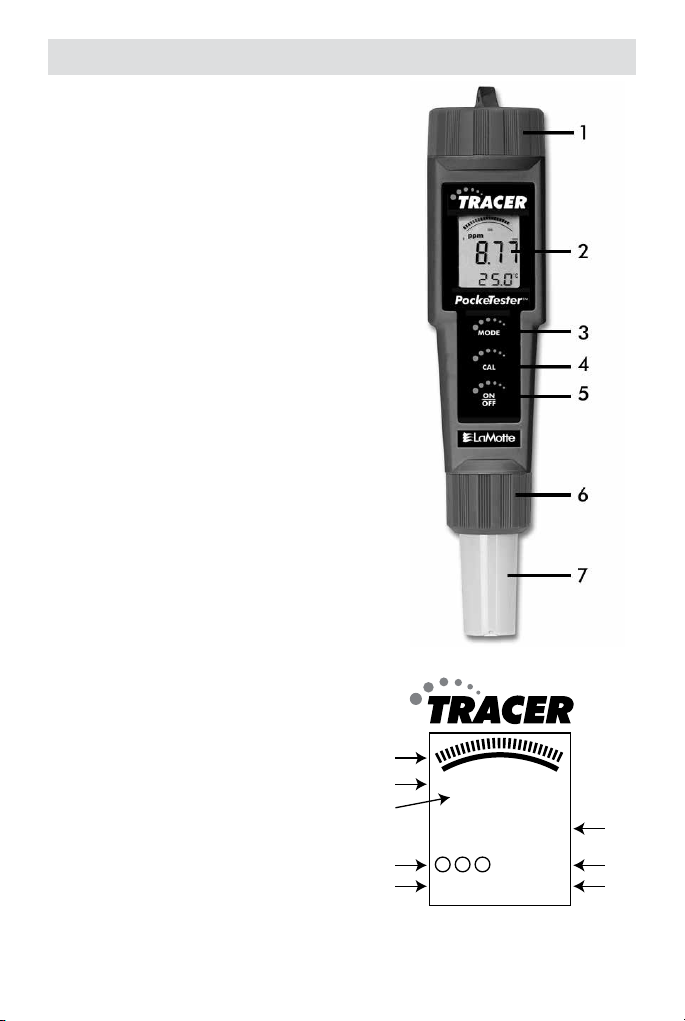
METER DESCRIPTION
Front Panel Description
1. Battery compartment cap
2. LCD display
3. MODE button
4. CAL button
5. ON/OFF button
6. Electrode collar
7. Electrode
(Note: The Electrode cap is not shown)
TRACER DISPLAY
1. Bar graph reading
2. Bar graph scale designations
3. Units of measure
4. Calibration indicators
5.
RENEW and CAL indicators
6. Measurement reading
7.
BAT (low battery) and
HOLD (data hold) indicators
8. Temperature display
1
2
3
4
5
7.0
500
2.0
0
10.04
BAT HOLD
1074
RENEW
78.6
CAL
12
1000
mvpHppm
6
7
°C
8
°F
5
Page 6

BASIC OPERATION
Powering the TRACER
If the batteries are weak, the BAT indicator will appear on the display. Press
the ON/OFF button to turn the TRACER on or off. The auto power off feature
will shut the TRACER off automatically after 10 minutes of inactivity.
Automatic Electrode Recognition
When the TRACER is turned on, it will recognize the type of electrode that
is connected and will display the appropriate unit of measure. An electrode
must be attached before turning the meter on.
Changing the Displayed Temperature Units
Press and hold the CAL button for approximately 3 seconds. The °C or °F icon
will change first and the numerical temperature value will change only after
the button is released.
NOTE: If the calibration mode is accidentally accessed and
the display, turn the TRACER off and begin again.
CAL appears on
Data Hold
Press the MODE button to freeze the current reading. The HOLD display icon
will appear along with the held reading. The held reading will be stored in
memory. Press the MODE button to return to normal operation.
DISPLAY MESSAGES
CAL Reminder
When the TRACER is turned on for the 15th time, without recalibration the
CAL icon will appear on the display indicating the the TRACER may require
calibration. Some applications may require recalibration of the electrode
sooner than others. The
pH electrode is recalibrated.
CAL display is a reminder and will turn off when the
RENEW
A flashing “RENEW” warning indicates that the probe may be nearing the end
of its useful life. If cleaning or recalibration does not cause the
to disappear, replace the electrode (see optional accessories). The
display appears when the output of the pH electrode fails a diagnostic test.
6
Renew icon
Renew
Page 7

pH TESTING
Overview
pH is a unit of measure (ranging from 0 to 14 pH) indicating the degree of
acidity or alkalinity of a solution. pH tests are the most commonly performed
measurements in water analysis, using the negative log of the hydrogen ion
activity of a solution which is an indicator of acidity or alkalinity. Solutions
with a pH of less than 7 are considered acidic, solutions with a pH of
higher than 7 are known as bases, and solutions with a pH of exactly 7 are
considered neutral.
The pH scale is logarithmic, so, for example, if Sample A is 1 pH less than
Sample B, this means that sample A is 10 times more acidic than Sample B.
A difference of 1 pH represents a ten-fold increase or decrease in acidity.
pH Display
When the electrode is placed in a solution, the main display and bar graph
will indicate the pH reading while the lower display will read temperature.
Readings flash until they have stabilized. The bar graph is ‘center zero’, i.e. at
pH 7 there is no display. As the pH rises, the bar will move from the center to
the right. If the pH drops, the bar will move from the center to the left.
Getting Started
1. Remove the cap from the bottom of the TRACER to expose the
electrode glass surface and reference junction.
2. Before first use or after storage, soak the electrode (with cap
removed) in a pH 4 buffer or tap water for 10 minutes.
3. Before first use, hold the meter by the top battery compartment
and swiftly tap the back of the meter downward into your palm (not
a hard surface). This assures that the internal electrolyte solution
moves to the very tip of the electrode. The electrolyte should fill the
circular junction window at the tip of the electrode.
4. White KCl crystals may be present in the cap. These crystals will
dissolve in the soak or they can be rinsed off with tap water.
5. Always calibrate close to the expected measurement value.
6. A sponge is located in the electrode protective cap. Keep this sponge
soaked with a pH 4 solution to prolong the life of the electrode during
storage.
7
Page 8

Preparation of Buffers
1. Fill a sample cup with 20 mL of distilled or deionized water.
2. Add one buffer tablet:
pH 4.0 Code 3983A
pH 7.0 Code 3984A
pH 10.0 Code 3985A
3. Use the tablet crusher (0175) to crush the tablet. Stir until the tablet
has disintegrated.
NOTE: Buffers should be prepared fresh daily.
pH Calibration
The TRACER can be calibrated at 1, 2 or 3 points. For the most accurate
results with a two point calibration, calibrate the TRACER with a pH 7 buffer
first, then calibrate with either a pH 4 or pH 10 buffer whichever is closest
to the pH value of the sample to be tested. When performing a three point
calibration, calibrate with the pH 7 buffer first, followed with the pH 4 buffer
and then the pH 10 buffer. For the most accurate results, always calibrate at
the sample temperature.
1. Place the electrode into a buffer solution (4, 7, or 10 pH) and press
the CAL button. Typically, pH 7 is calibrated first, then 4 or 10,
depending on the measurement range. If readings are going to be
made over the entire range, calibrate with 4, 7 and 10 buffers.
2. The TRACER will automatically recognize the solution and calibrate
itself to that value. The circled number on the display will match the
pH of the buffer.
Note that if the buffer is more than 1 pH unit off from the 4, 7, or 10
pH buffer, the TRACER will assume an error and abort the calibration.
CAL and END will be displayed.
3. During calibration, the pH reading will flash on the main display.
4. When calibration is complete, the TRACER will automatically display
END and return to the pH measurement mode.
5. Rinse the electrode with distilled water.
6. The appropriate circled indicator (4, 7, or 10) will appear on the
display when a calibration has been completed. The calibration will be
stored until a new calibration is performed.
7. For a two- or three-point calibration, repeat Steps 1-5.
8. The meter should be calibrated before each use to obtain the most
accurate results.
8
Page 9

9. Always turn the meter off and then on before calibrating to allow
sufficient
the meter auto powers off during calibration the calibrations remain
valid, but new calibrations will turn the circled indicators off.
time to complete the calibrations during one power cycle. If
Meter Reset
If the meter will not calibrate or displays a -1, reset the meter and attempt
to re-calibrate.
1. Turn off the meter.
2. Remove the battery cartridge from the top of the meter.
3. Press the ON/OFF button for 10 seconds to bleed off all charges
within the meter.
4. Re-insert the batteries and turn the meter on.
5. Follow the pH Calibration procedure.
pH Measurement
1. Place the electrode in the test sample.
2. Record the pH after the reading becomes stable and the display
stops flashing.
3. Press the ON/OFF button to turn the meter off. Rinse the electrode
with distilled water. Replace cap
pH Measurement of Soil
1. Place a 1:1 ratio of soil and distilled water in a small beaker. For most
analyses, 20 grams of soil and 20 grams distilled water are sufficient.
2. Wait 15 minutes. Stir occasionally with a stirring rod.
3. Stir the sample. Immediately place the electrode in the sample.
4. Wait until the display stabilizes. Record the pH.
5. Rinse the electrode in distilled water. Replace cap.
NOTE: The flat surface electrode will allow for readings directly from the soil
if there is enough moisture present in the soil.
Storing Readings
1. After the reading is made press the
MODE button to store the current
reading The storage location number
will be displayed followed by the
reading being stored.
4
pH
10.04
HOLD
HT4
78.6
°F
9
Page 10

2. Press the MODE button to return to normal operation.
3. Repeat step 1 to store the next reading.
4. If an attempt is made to store more
readings (starting with the first reading) will be overwritten.
than 15 readings, the stored
Recalling Stored Readings
NOTE: First ensure that the HOLD symbol is not displayed. If it is, exit the
MODE function by pressing the MODE button.
1. Press the CAL button once and then press the MODE button
immediately after
15) will flash. If the CAL mode is accidentally accessed (display
flashing), press the CAL button again to exit.
2. The last stored reading taken will be displayed first. To advance
through the stored readings, press the MODE button. The location
number is displayed first, followed by the reading stored in that
location.
3. To exit the recall mode, press the CAL button and the TRACER
return to normal operation. If the batteries are removed, any stored
readings and user calibrations will be discarded.
CAL is displayed; the location number (1 through
will
MAINTENANCE
Care/Storage of Electrode
1. Always rinse the electrode in tap, distilled or deionized water between
measurements to avoid cross-contamination of the samples. Double
is recommended when high accuracy is required.
rinsing
2. To preserve electrode life keep the sponge in the protective cap
soaked with a pH 4 buffer. Cap TRACER when not in use. Store
vertically.
Do Not allow sensor to dry out.
3. Do not touch the electrodes. Touching the surface of the electrodes
may damage and reduce the life of the electrodes.
4. Salt deposits may build up in the storage cap and should periodically
rinsed away. These deposits could affect measurements at low
be
conductivity.
10
Page 11

Battery Replacement
1. Twist off the battery compartment cap.
2. Hold the battery housing in place with one finger. Remove the battery
carrier by pulling on the small tabs.
3. Replace the four CR2032 batteries. Observe polarity.
4. Replace the battery compartment cap.
NOTE: If the batteries are removed, stored data and user calibrations
will be cleared. A new user calibration will be required. Factory
calibrations will be retained.
All EU users are legally bound by the Battery Ordinance to
return all used batteries to community collection points or
wherever batteries/accumulators are sold.
Disposal in household trash or refuse is prohibited.
DISPOSAL: Follow the valid legal stipulations in respect of the disposal of the
device at the end of its life cycle
Other Battery Safety Reminders
¬ Never dispose of batteries in a fire. Batteries may explode or leak.
¬ Never mix battery types. Always install new batteries of the same type.
Cleaning and Conditioning the Electrode
Surface Cleaning – Only in case of visible surface contamination or if
readings should become erratic, use a disposable laboratory towel wetted
with ethanol or isopropyl alcohol and gently rub the surface, until no more
residue is visible.
11
Page 12

Replacing the Electrode
The TRACER is shipped with an electrode attached. Electrode life is limited
and is dependant on the frequency of use and care. If the electrode needs to
be replaced, follow these steps for removing and connecting electrodes.
1. Turn meter off.
2. To remove the electrode, turn the collar counter-clockwise and
remove it.
3. Gently rock the electrode from side to side, pulling it downwards, until
it disconnects from the meter.
4. To attach an electrode, carefully plug the electrode into the meter
socket. Note that the electrode connector is keyed to ensure a proper
connection.
CAUTION: Take case to align pins carefully. Bent or broken ins will
cause the meter to malfunction.
5. Tighten the electrode collar firmly enough to make a good seal. A
rubber gasket will seal the electrode with the meter.
12
Page 13

TROUBLESHOOTING
Power on
but no display
Unstable
readings
Slow response
time or reading
drift
Dry bulb Dehydrated membrane,
Static charge Wiping electrode Rinse electrode in 4.0 buffer and
Same readings
in different
buffers and
samples
Batteries Insert batteries
Batteries Verify correct polarity
Batteries Replace batteries
Electrode Immerse electrode more deeply
Electrode Condition electrode before first
Electrode Remove air bubbles caught
Electrode Clean electrode
Electrode Replace electrode
Clogged junction Soak in 4.07M Potassium
Strong alkaline
measurement
Deteriorated gel layer Replace electrode
Protein coating on
electrode surface
Oil, paint, dyes,
suspended solids on
electrode
long term storage
without wetting
Cracked or broken
electrode
in sample
use
under electrode
Chloride (KCl) at 60°C for 30
minutes
Soak in 0.1M Hydrochloric acid
(HCl) overnight
Soak in 1g Pepsin dissolved in 10
mL of 0.1M HCl for 30 minutes or
as needed
Rinse electrode alternately with
materials solvent then a buffer
7.00
Soak electrode tip in wetting cap
filled with 1 mL 4.0 buffer for
24-48 hours
blot. Do not wipe electrode
Replace electrode. Use bulb
guard. Avoid plunging electrode
into bottom of container and stir
bars.
13
Page 14

Erratic LCD
display
Unexpected
readings
Display frozen HOLD function Press MODE or turn meter off
Steady “-1 ”
display
Samples have low ionic
strength (lack salt);
e.g. distilled, deionized,
boiled, lake water (high
pressure)
Buffers Calibrate with fresh buffers
Buffers Calibrate with buffers that
Button response Remove batteries press ON/OFF
Wait Reading not stable yet
For each 50 mL of sample add
1 drop (50 mL) of saturated
Potassium Chloride (KCl). No
alteration in pH will occur by
inert KCl.
bracket sample pH
button for 3 seconds. Reinsert
batteries (stored data will be
lost)
If the meter will not calibrate or displays a -1, reset the meter and attempt
to re-calibrate.
1. Turn off the meter.
2. Remove the battery cartridge from the top of the meter.
3. Press the ON/OFF button for 10 seconds to bleed off all charges
within the meter.
4. Re-insert the batteries and turn the meter on.
5. Follow the pH Calibration procedure.
¬ If the unit appears to be locked (display frozen) it is possible that the
Data Hold mode has been inadvertently accessed by pressing the
MODE button. Press the MODE button again or turn the meter off and
restart if the display appears frozen.
¬ If the meter does freeze and no button presses revive it, remove the
batteries, press the ON button for 10 seconds and then reinsert the
batteries.
¬ If the batteries are removed, any stored readings will be discarded and
the user calibration data for pH will be cleared. New user pH calibration
data is required. However, factory calibration data will be retained.
14
Page 15

EXPAND YOUR TRACER
Interchangeable electrodes are available to convert the pH TRACER to a Total
Chlorine TRACER or an ORP TRACER.
Remember to ask for instructions and appropriate reagents or buffer tablets
when ordering the Total Chlorine or ORP electrodes.
Total Chlorine TRACER Electrode, 0.0-10.0 ppm
The Total Chlorine TRACER Electrode (Code 1732) requires the
use of TRACER TCL Tablets. Order Code 7044-J (100 pack).
ORP TRACER Electrode, ±999 mV
The ORP TRACER Electrode (Code 1734) requires an initial
soaking in a pH 4.0 buffer solution. Order pH 4.0 Mini Buffer
Tablets/100 pack (Code 3893-J).
Code 1732
Code 1734
SAFETY
¬ This device is not a toy. Keep out of the hands of children. It contains
hazardous objects as well as small parts that children could swallow.
If a child swallows any part of this instrument, contact a physician
immediately.
¬ Do not leave batteries and packing material unattended. They can be
dangerous to children if used as toys.
¬ If the device is going to be unused for an extended period of time,
remove the batteries to prevent draining.
¬ Expired or damaged batteries can cause cauterization on contact with
the skin. Always use the appropriate gloves and safety precautions
when handling batteries.
¬ Do not allow the batteries to short-circuit or throw batteries into a fire.
15
Page 16

WARRANTY
LaMotte Company warrants this instrument to be free of defects in parts
and workmanship for 1 year from the date of shipment and warrants this
probe to be free of defects in parts and workmanship for 6 months from the
date of shipment. If it should become necessary to return the instrument for
during or beyond the warranty period, contact our Technical Service
service
Department
at 1-800-344-3100 or tech@lamotte.com for a return authorization
number or visit www.lamotte.com for troubleshooting help. The sender is
responsible for
to prevent damage in
resulting from action of the
outside of specification, improper
modification. LaMotte Company specifically disclaims any implied
warranties or merchantability or fitness for a specific purpose and will
not be liable for any direct, indirect, incidental or
LaMotte Company’s total liability is limited to repair or
product. The warranty set forth above is inclusive and no other warranty,
whether written or oral, is expressed or implied.
To register your meter with the LaMotte Service Department,
go to www.lamotte.com
shipping charges, freight, insurance and proper packaging
transit. This warranty does not apply to defects
user such as misuse, improper wiring, operation
maintenance or repair, or unauthorized
consequential damages.
replacement of the
and choose SUPPORT on the top navigation bar.
16
Page 17

17
Page 18

INTRODUCTION
Félicitations pour votre achat de la TRACER PockeTester. This est livré
entièrement testé et calibré et, avec une utilisation correcte, vous fournira
des années de service fiable.
SPÉCIFICATIONS
Afficheur écran à cristaux liquides avec graphique à
Conditions de fonctionnement 0 à 50°C (32 à 122°F) / < 80% RH
Registre et précision 0,00 à 14,00 / ± 0,01pH type
Compensation de température Automatique de 0 à 90°C (32 à 194°F)
Registre de température -5 à 90°C (23 à 194°F)
Résolution de température de 0,1° à 99,9 puis 1° par la suite
Précision de température ± 1°C / 1,8°F [de -5 à 50°C (23 à 122°F)]
Stockage des mesures 15 lectures étiquetées (numérotées)
Alimentation Quatre (4) piles bouton CR2032
Indication de piles faibles "BAT" (piles) apparaît sur l'afficheur
Coupure automatique après 10 minutes d'inactivité
Dimensions 1.4 x 6.8 x 1.6” (35.6 x 172.7 x 40.6 mm),
Dimensions 40 x 187 x 40 mm (1,6 x 7,4 x 1,6”)
Poids 87 g (87,88 g)
barres
± 3°C / 5,4°F [de 50 à 90°C (122 à 194°F)]
3.85 oz (110g)
18
AVERTISSEMENT ! Ce kit contient des
produits chimiques qui peuvent être nocifs s’ils sont utilisés de façon impropre.
Lisez avec attention les avertissements
sur chaque récipient. Ce produit n’est
pas destiné à être utilisé par des enfants,
sauf sous la surveillance d’un adulte.
Page 19

PIÈCES ET ACCESSOIRES
Électrode de rechange pH Code 1733
Support lesté avec récipients d’échantillon (5) Code 1746
Récipients d’échantillon avec bouchons (24) Code 1745-24
Pastilles tampon mini pH 4,0 (100) Code 3983A-J
Pastilles tampon mini pH 7,0 (100) Code 3984A-J
Pastilles tampon mini pH 10,0 (100) Code 3985A-J
CONTENTS
Kit TRACER PockeTester pH, plage de pH 0,00-14,00 Code 1741
Comprend : Un récipient d’échantillon avec bouchon †
Un broyeur de pastille
Des pastilles tampon pH 4,0, 7,0 et 10,0 †
†Produit non vendu dans cette quantité. Reportez-vous à la section Pièces et accessoires.
*AVERTISSEMENT : Les réactifs signalés par une astérisque * sont considérés comme
représentant des dangers potentiels pour la santé. Pour afficher ou imprimer les fiches de
données de sécurité (FDS) de ces réactifs, accédez à www.lamotte.com. Cherchez le code
à quatre chiffres du réactif indiqué sur l’étiquette du réactif, dans la liste du contenu ou
dans les procédures d’analyse. Ignorez toute lettre précédant ou suivant le code à quatre
chiffres.
Par exemple, si le code est 4450WT-H, tenez compte uniquement de 4450. Pour obtenir
une version imprimée, contactez LaMotte par courriel, téléphone ou fax.
En cas d’urgence, des informations pour tous les réactifs LaMotte sont disponibles auprès
de Chem-Tel : (US 1-800-255-3924) (appel international, en PCV, 813-248-0585).
Pour commander à nouveau des réactifs ou des composants de kit d’analyse séparément,
utiliser les numéros de code indiqués.
Code 0175
19
Page 20

DESCRIPTION DE TRACER
Panneau de commandes avant
1. Couvercle du logement des piles
2. Afficheur LCD
3. Touche de fonction MODE
4. Touche de fonction CAL (Étalonnage)
5. Touche ON/OFF (en marche/arrêt)
6. Collet à électrodes
7. Électrode
(Le capuchon à électrodes n'est pas illustré)
Affichage
1. Lecture du graphique à barres
2. Lecture de mesures
3. Indicateurs BAT (piles faibles)
Et HOLD (maintien des données)
4. Affichage de la température
5. Désignations d'échelle du
graphique à barres
6. Unités de mesure
7. Indicateurs d’Étalonnage
8. Indicateurs RENEW
(remplacer) et CAL (Étalonnage)
1
2
3
4
5
7.0
500
2.0
0
10.04
BAT HOLD
1074
RENEW
78.6
CAL
12
1000
mvpHppm
6
7
°C
8
°F
20
Page 21

FONCTIONNEMENT DE BASE
Alimentation du TRACER
Appuyez sur la touche ON/OFF (en marche/arrêt) pour allumer ou
éteindre le TRACER. L'option de coupure automatique éteint le TRACER
automatiquement après 10 minutes d'inactivité afin de préserver la vie de la
pile.
Reconnaissance automatique de l'électrode
Lorsque le TRACER est en marche, il reconnaît le type d'électrode qui y est
branchée et affiche l'unité de mesure appropriée. Attachez l'électrode avant
de mettre en marche le TRACER.
Modifier les unités de température affichées
Appuyez et maintenez enfoncé la touche CAL (Étalonnage) pendant environ
3 secondes. L'icône °C ou °F changera d'abord et la valeur de température
numérique changea dès que la touche sera relâché. Si vous accédez
par erreur au mode d’étalonnage, le mot CAL (Étalonnage) apparaîtra
sur l'afficheur. Éteignez simplement le TRACER et faites-le démarrer de
nouveau.
Maintien des données
Appuyez sur la touche MODE pour geler la lecture actuelle. L'icône HOLD
(maintien) apparaîtra en même temps que la lecture du maintien. La lecture
du maintien sera également entreposée en mémoire. Appuyez sur la touche
MODE pour revenir en position normale de fonctionnement.
AFFICHER LES MESSAGES
Afficher le rappel CAL
Lorsque le TRACER est mis en marche en mode pH pour la 15ème fois
sans avoir été recalibré, l'icône CAL (Étalonnage) apparaît sur l'afficheur,
indiquant que le TRACER pourrait avoir besoin d'être recalibré. Certaines
applications peuvent exiger l’étalonnage de l'électrode plus souvent que
d'autres. L'affichage CAL est tout simplement un rappel et s'éteindra
lorsque l'électrode du pH sera recalibrée.
Affichage RENEW (renouveler)
Un témoin avertisseur clignotant "RENEW" indique que la sonde arrive peutêtre à la fin de sa durée de vie utile. Si le nettoyage ou l’étalonnage ne fait
pas disparaître l'icône RENEW (renouveler), remplacez l'électrode. RENEW
apparaît sur l'afficheur lorsque la sortie de l'électrode pH échoue au test
diagnostique.
21
Page 22

TEST DE pH
Sommaire
Le pH est une unité de mesure (allant de 0 à 14pH) qui indique le degré
d'acidité ou d'alcalinité d'une solution. Les tests de pH sont les mesures
les plus communément effectuées lors des analyses d'eau et ils rendent
compte du logarithme négatif de l'activité des ions d'hydrogène d'une
solution, ce qui est un signe d'acidité ou d'alcalinité. Les solutions affichant
un pH inférieur à 7 sont considérées comme acides, celles avec un pH
supérieur à 7 sont appelées bases, et finalement les solutions dont le pH est
exactement de 7 sont neutres.
L'échelle du pH est logarithmique, par conséquent, si l'échantillon A affiche
un pH de 1 de moins que l'échantillon B, cela signifie que l'échantillon a est
10 fois plus acide que l'échantillon B. Une différence de pH de 1 représente
une différence d'acidité de facteur 10.
Affichage du pH
Lorsque l'électrode est placée dans une solution, l'afficheur principal et
le graphique à barres indiquent la lecture du pH tandis que l'afficheur
inférieur lit la température (les lectures clignotent jusqu'à ce qu'elles soient
stabilisées). Le graphique à barre est à "zéro centre", c'est-à-dire qu'à un
pH de 7, rien ne s'affiche. À mesure qu'augmente le pH, la barre se déplace
du centre vers la droite. Si le pH baisse, la barre se déplace du centre vers la
gauche.
Guide d’utilisation
1. Enlevez le bouchon au bas du TRACER pour libérer la surface de verre
de l’électrode et la jonction de référence.
2. Avant toute utilisation ou après stockage, faites tremper l’électrode
(sans le bouchon) dans une solution tampon pH 4 ou de l’eau du
robinet pendant 10 minutes.
3. Avant toute utilisation, maintenez l’instrument par le haut, au
niveau du compartiment des piles, et tapotez sèchement l’arrière
de l’instrument dans la paume de votre main (non sur une surface
dure). Ainsi, la solution d’électrolyte interne se déplace tout au bout
de l’électrode. L’électrolyte doit remplir la fenêtre ronde de jonction
au bout de l’électrode.
4. Des cristaux blancs de chlorure de potassium peuvent se trouver
dans le bouchon. Ces cristaux seront dissous lors du trempage,
sinon vous pouvez les éliminer par un rinçage à l’eau du robinet.
5. Étalonnez toujours proche de la valeur de mesure attendue.
22
Page 23

6. Le bouchon de protection de l’électrode contient une éponge. Faites
en sorte que cette éponge soit toujours imbibée de solution pH 4
pour augmenter la durée de vie de l’électrode pendant le stockage.
Préparation des solutions tampon
1. Remplissez un récipient d’échantillon avec 20 mL d’eau distillée ou
désionisée.
2. Ajoutez une pastille tampon :
pH 4,0 Code 3983A
pH 7,0 Code 3984A
pH 10,0 Code 3985A
3. Utilisez le broyeur (0175) pour triturer la pastille. Mélangez jusqu’à
ce que la pastille se soit dissoute.
REMARQUE : Les solutions tampon doivent être fraîches et préparées
quotidiennement.
Étalonnage du pH (1, 2 ou 3 points)
Un étalonnage à deux points avec un tampon de 7 puis 4 ou 10 (selon celui
qui se rapproche le plus de la valeur échantillon prévue) est recommandée.
Un étalonnage à un point (choisissez la valeur la plus rapprochée de la
valeur de votre échantillon prévue) est également valide. Pour une plus
grande exactitude, calibrez toujours selon la température de l'échantillon.
1. Placez l'électrode dans une solution tampon (de 4, 7 ou 10) et
appuyez sur la touche CAL. Le pH de 7 doit être calibré le premier,
puis le 4 et/ou le 10.
2. Le TRACER reconnaît automatiquement la solution et étalonne à
cette valeur. Remarque : Si la solution est supérieure de 1pH du 4,
7 ou 10 pH standard, le TRACER assumera qu'il s'agit d'une erreur
et avortera l’étalonnage. Les mots CAL (étalonnage) et END (fin)
s'afficheront.
3. Pendant l’étalonnage, la lecture du pH clignote sur l'afficheur
principal.
4. Lorsque l’étalonnage est complété, le TRACER affiche
automatiquement END (fin) et revient en mode de fonctionnement
normal.
5. L'indicateur encerclé approprié (4, 7, 10) ou apparaîtra sur l'afficheur
lorsqu'un étalonnage a été complété. Les données d’étalonnage sont
entreposées jusqu'à ce qu'un nouveau étalonnage soit effectué.
6. Pour un étalonnage à deux ou trois points, répétez les étapes 1 à 4.
23
Page 24

Remarque : éteignez toujours le compteur puis rallumez-le avant
l’étalonnage pour allouer une période suffisante afin de compléter les
étalonnages pendant un cycle d'impulsion motrice. Si le compteur
s'éteint automatiquement pendant l’étalonnage, l’étalonnage
demeure valide mais de nouveaux étalonnages éteindront les
indicateurs encerclés.
Remarque: La compensation automatique de température (ATC)
de circuit n'est pas actif lors de l'étalonnage. Pour assurer un
étalonnage plus précis, assurez-vous que les tampons d'étalonnage
sont à 25 °C (77 °F).
RAZ
Si le compteur ne se calibre pas ou affiche un -1, réinitialiser le compteur et
la tentative de re-calibrer.
1. Éteindre le lecteur.
2. Retirez la batterie du haut de l'appareil.
3. Appuyez sur le bouton Marche / Arrêt pendant 10 secondes pour
purger toutes les charges au sein de l'appareil de mesure.
4. Réinsérez les piles et allumez l'appareil.
5. Tentative de ré-étalonner l'appareil.
Mesure du pH
1. Placez l’électrode dans l’échantillon à analyser.
2. Enregistrez le pH une fois que le résultat est stable et que l’affichage
cesse de clignoter.
3. Appuyez sur le bouton ON/OFF pour éteindre l’instrument. Rincez
l’électrode à l’eau distillée. Remettez le bouchon.
Mesure du pH du sol
1. Mettez de la terre et de l’eau distillée dans un petit bécher en
proportion 1:1. Pour la plupart des analyses, 20 grammes de terre et
20 grammes d’eau distillée sont suffisants.
2. Patientez 15 minutes. Mélangez de temps en temps à l’aide d’un
bâtonnet agitateur.
3. Mélangez l’échantillon. Placez immédiatement l’électrode dans
l’échantillon.
4. Patientez jusqu’à ce que l’affichage se stabilise. Enregistrez le pH.
5. Rincez l’électrode à l’eau distillée. Remettez le bouchon.
24
Page 25

REMARQUE : La surface plane de l’électrode permet de mesurer le pH
directement à partir du sol si ce dernier est suffisamment humide.
Lectures entreposées dans la mémoire
1. Appuyez sur la touche MODE pour entreposer une lecture. L'afficheur
affichera brièvement le numéro d'emplacement de la mémoire, puis
la valeur entreposée. (Le maintien des données s'activera).
2. Appuyez sur la touche MODE de nouveau pour revenir en position
normale de fonctionnement.
3. Répétez l'étape 1 pour entreposer la
lecture suivante et ainsi de suite.
4. Après un entreposage de 15 lectures,
le TRACER reviendra à l'emplacement
mémoire 1 et commencera à
remplacer les données existantes par
les données nouvellement entreposées.
4
pH
10.04
HOLD
HT4
78.6
Rappeler les lectures entreposées
Remarque : Vérifiez que le symbole HOLD n'est pas affiché. Si c'est le cas,
sortez de la fonction HOLD en appuyant sur la touche MODE.
1. Appuyez sur la touche CAL puis appuyez sur la touche MODE
immédiatement après que CAL ait été affiché ; le numéro
d'emplacement de stockage (de 1 à 15) clignotera. Si vous avez
accédé accidentellement au mode CAL (l'afficheur clignote), appuyez
sur la touche CAL de nouveau pour sortir.
2. La dernière lecture stockée s'affichera la première. Pour avancer
parmi les lectures stockées, appuyez sur la touche MODE. Le numéro
d'emplacement s'affiche en premier, suivi de la lecture stockée dans
cet emplacement.
3. Pour sortir du mode recall (rappeler), appuyez sur la touche CAL et le
TRACER reviendra en mode de fonctionnement normal.
°F
25
Page 26

ENTRETIEN
Entretien/stockage de l’électrode
1. Rincez toujours l’électrode avec de l’eau du robinet, de l’eau
distillée ou de l’eau désionisée entre chaque mesure pour éviter la
contamination croisée entre les échantillons. Rincez deux fois si vous
avez besoin de résultats très précis.
2. Pour augmenter la durée de vie de l’électrode, faites en sorte
que l’éponge du bouchon de protection soit toujours imbibée de
solution pH 4. Rebouchez le TRACER lorsque vous ne l’utilisez pas.
Stockez-le à la verticale. Ne laissez pas le capteur sécher.
3. Ne touchez pas les électrodes. Si vous touchez la surface des
électrodes, vous risquez de les endommager et de réduire leur durée
de vie.
4. Des dépôts de sel peuvent se former dans le bouchon de stockage. Ils
doivent être éliminés. Pour ce faire, rincez régulièrement le bouchon.
Ces dépôts peuvent fausser les mesures en cas de conductivité
faible.
Remplacement des piles
1. Dévissez le couvercle du compartiment des piles
2. Maintenez le compartiment des piles avec un doigt, retirez le support
des piles en tirant sur les deux languettes.
3. Reinsérez les quatre (4) piles CR2032 en respectant la polarité.
4. Refermez le compartiment des piles
REMARQUE : Si vous enlevez les piles, toutes les mesures
enregistrées seront supprimées et les données d’étalonnage
utilisateur du pH seront effacées. Vous devrez effectuer un nouvel
étalonnage du pH. Toutefois, l’étalonnage d’usine sera conservé.
26
Page 27

Ne jetez jamais les piles ou batteries rechargeables dans
les déchets ménagers. En tant que consommateurs, les
utilisateurs sont légalement tenus de prendre les au lieu de
collecte, le magasin de détail où les batteries ont été achetés,
ou partout où les batteries sont vendues.
Élimination : ne pas disposer de cet instrument dans les déchets ménagers.
L’utilisateur s’engage à retirer de la périphériques à un point de collecte pour
l’élimination des équipements électriques et électroniques.
Autres Batterie sécurité Rappels
¬ Ne jetez jamais les batteries au feu. Les piles peuvent exploser ou fuir.
¬ Ne jamais mélanger les types de piles. Toujours installer des piles
neuves du même type.
Nettoyage et conditionnement de l’électrode
Nettoyage de la surface : uniquement en cas de contamination visible de la
surface ou de résultats incohérents, imbibez un papier absorbant jetable
de laboratoire avec de l’éthanol ou de l’alcool isopropylique et frottez
délicatement la surface jusqu’à ce que tout résidu ait disparu.
Remplacement des électrodes
Le TRACER est expédié avec une électrode attachée. La durée de vie de
l'électrode est limitée et elle dépend (entre autres facteurs) de la fréquence
de l'utilisation et du soin que vous en prenez. Si elle doit être remplacée,
suivez ces étapes pour retirer et rebrancher les électrodes.
1. Pour retirer une électrode, dévissez et retirez complètement
l'électrode qui retient le collet.
2. Secouez doucement l'électrode d'un côté à l'autre, en la tirant pour
la débrancher du compteur.
3. Pour la rattacher, branchez avec soin l'électrode dans la douille du
compteur (prenez note que le connecteur de l'électrode est à accès
direct, afin d'assurer une connexion adéquate).
4. Fixez l'électrode en serrant solidement le collet. (un joint
d'étanchéité en caoutchouc scelle l'électrode sur le compteur).
27
Page 28

DÉPANNAGE
Problème Cause Solution
L’instrument
s’allume
mais rien ne
s’affiche
Résultats
instables
Temps de
réponse lent
ou dérive du
résultat
Tête
asséchée
Piles Insérez les piles
Piles Vérifiez que la polarité est
Piles Changez les piles
Électrode Immergez davantage l’électrode
Électrode Conditionnez l’électrode avant de
Électrode Enlevez les bulles d’air coincées
Électrode Nettoyez l’électrode
Électrode Changez l’électrode
Jonction bouchée Laissez tremper l’électrode dans
Mesure des alcalins élevée Laissez tremper l’électrode
Couche de gel détériorée Changez l’électrode
Couche de protéines à la
surface de l’électrode
Présence d’huile, de
peinture, de colorants, de
matières en suspension
sur l’électrode
Membrane déshydratée,
long stockage sans
imbibition
respectée
dans l’échantillon
l’utiliser
sous l’électrode
une solution de chlorure de
potassium (KCI) 4,07 M à 60 °C
pendant 30 minutes
dans une solution d’acide
hydrochlorique (HCI) 0,1 M toute
une nuit
Faites tremper l’électrode dans
une solution composée de 1 g de
pepsine dissout dans 10 mL de
solution HCI 0,1 M pendant 30
minutes ou autant que nécessaire
Rincez l’électrode avec des
solvants, puis avec une solution
tampon 7,00
Laissez tremper le bout de
l’électrode dans le bouchon
rempli de 1 mL de solution
tampon 4,0 pendant 24-48
heures
28
Page 29

Charge
statique
Résultats
identiques
pour
différentes
solutions
tampon et
différents
échantillons
Affichage
LCD instable
Résultats
inattendus
Affichage
bloqué
« -1 »
s’affiche en
continu
Électrode essuyée Rincez l’électrode avec une
Électrode fendue ou
endommagée
Les échantillons
présentent une faible
force ionique (manque
de sels) ; par exemple,
eau distillée, désionisée,
bouillie, eau de lac
(pression élevée)
Solutions tampon Étalonnez avec des solutions
Solutions tampon Étalonnez avec des solutions
Fonction HOLD Appuyez sur MODE ou éteignez
Réponse de bouton Enlevez les piles et appuyez sur
Attente Le résultat n’est pas encore
solution tampon 4,0 et épongez.
N’essuyez pas l’électrode
Changez l’électrode. Utilisez
la protection pour la tête de
l’électrode. Évitez de mettre en
contact l’électrode avec le fond
des récipients et les agitateurs.
Pour chaque volume d’échantillon
de 50 mL, ajoutez une goutte (50
mL) de chlorure de potassium
saturé (KCI). La valeur du pH ne
variera pas avec du KCI inerte.
tampon fraîches
tampon comprenant le pH de
l’échantillon
l’instrument
le bouton ON/OFF pendant 3
secondes. Remettez les piles
(les données enregistrées seront
perdues)
stable
Si vous ne parvenez pas à étalonner l’instrument ou si -1 s’affiche,
réinitialisez l’instrument et essayez à nouveau de l’étalonner.
1. Éteignez l’instrument.
2. Enlevez le compartiment des piles situé en haut de l’instrument.
3. Appuyez sur le bouton ON/OFF pendant 10 secondes pour évacuer
29
Page 30

toute charge de l’instrument.
4. Remettez les piles en place et allumez l’instrument.
5. Suivez la procédure d’étalonnage du pH.
¬ Si l’appareil semble verrouillé (affichage bloqué), il est possible
que le mode de mémorisation des données ait été sélectionné par
inadvertance en appuyant sur le bouton MODE. Appuyez sur le bouton
MODE à nouveau ou éteignez l’instrument, puis redémarrez-le si
l’affichage est bloqué.
¬ Si l’instrument se bloque et que vous ne parvenez pas à le débloquer
en appuyant sur les boutons, appuyez sur le bouton ON pendant 10
secondes, puis remettez les piles.
¬ Si vous enlevez les piles, toutes les mesures enregistrées seront
supprimées et les données d’étalonnage utilisateur du pH seront
effacées. Vous devrez effectuer un nouvel étalonnage du pH. Toutefois,
l’étalonnage d’usine sera conservé.
AUGMENTEZ LA CAPACITÉ DE VOTRE TRACER
Des électrodes interchangeables sont disponibles pour convertir le TRACER
pH en TRACER Chlore total ou TRACER Potentiel redox.
Pensez à demander les instructions et les réactifs et pastilles tampon
correspondants lorsque vous commandez les électrodes pour le chlore total
ou le potentiel redox.
Électrode TRACER Chlore total, 0,0-10,0 ppm Code 1732
L’électrode TRACER Chlore total (code 1732) requiert l’utilisation
de pastilles TRACER TCL. Code de commande 7044-J (paquet
de 100)
Électrode TRACER Potentiel redox, ±999 mV Code 1734
L’électrode TRACER Potentiel redox (code 1734) doit être
préalablement trempée dans une solution tampon pH 4,0.
Commandez des pastilles tampon mini pH 4,0/paquet de 100
(code 3893-J).
30
Page 31

CONSIDÉRATIONS
¬ Si l'appareil semble être verrouillé (l'afficheur est gelé), il est possible
que le mode de maintien des données ait été sélectionné par
inadvertance en appuyant sur la touche MODE. Appuyez simplement
de nouveau sur la touche MODE pour éteindre le compteur et le
redémarrer si l'afficheur est gelé.
¬ Si le compteur est verrouillé et qu'aucun bouton enfoncé ne le ranime,
retirez les piles, appuyez sur la touche ON (en marche) pendant 10
secondes puis réinsérez les piles.
¬ Prenez note que si les piles sont retirées, toute lecture stockée sera
effacée. Les données d’ étalonnage de l'utilisateur seront également
effacées. De nouvelles données d’étalonnage du pH utilisateur seront
nécessaires. Les données d’étalonnage de l'usine pour tous les
modèles seront toutefois retenues.
GARANTIE
LaMotte Company garantit que cet instrument est exempt de défauts
matériaux et de fabrication pendant 2 ans à partir de la date d’expédition et
garantit que la sonde est exempte de défauts matériaux et de fabrication
pendant 6 mois à partir de la date d’expédition S’il s’avérait nécessaire de
renvoyer l’instrument au service technique pendant ou au-delà de la période
de garantie, contactez notre service technique au 1-800-344-3100 ou à
l’adresse tech@lamotte.com afin d’obtenir un numéro d’autorisation de
retour ou accédez au site Web www.lamotte.com pour obtenir de l’aide
relative au dépannage. L’expéditeur est responsable des frais d’envoi, du
transport, de l’assurance et de l’emballage adéquat du produit afin que ce
dernier soit protégé contre les dommages qui pourraient survenir durant
le transport. La garantie ne s’applique pas aux défauts résultant de l’action
de l’utilisateur, telle qu’une utilisation impropre, un branchement incorrect,
un fonctionnement hors spécifications, un entretien ou une réparation
inappropriés, ou une modification non autorisée. LaMotte Company
décline expressément toute garantie implicite de qualité marchande ou de
convenance à une fin particulière et ne pourra en aucun cas être tenue pour
responsable de tout dommage consécutif, accessoire, indirect ou direct.
La responsabilité totale de LaMotte Company est limitée à la réparation et
au remplacement du produit. La garantie énoncée ci-avant est inclusive et
aucune autre garantie, écrite ou orale, n’est expresse ou implicite.
Pour enregistrer votre instrument auprès du service technique LaMotte
accédez à www.lamotte.com et cliquez sur SUPPORT dans la barre de
navigation.
31
Page 32

LaMOTTE COMPANY
Helping People Solve Analytical Challenges
PO Box 329 • Chestertown • Maryland • 21620 • USA
800-344-3100 • 410-778-3100 (Outside USA.) • Fax 410-778-6394
Visit us on the web at www.lamotte.com
1741-MN 08.18
 Loading...