

Page 1
CON 6/TDS 6
Meter Manual
The LaMotte 6 Series
Page 2

WARNING! This set contains chemicals
that may be harmful if misused. Read
cautions on individual containers
carefully. Not to be used by children
except under adult supervision
Page 3

CONTENTS
Introduction ..............................
Display & Keypad Functions ......................7
Display .................................. 7
Keypad ..................................
Preparation ...............................
Inserting & Removing Rubber Boot ................... 9
Inserting the Batteries .......................... 9
Battery Replacement ........................... 9
Conductivity Electrode Information .................. 10
Connecting the Probe to Meter ..................... 11
Turning the Meter On.......................... 12
Change Conductivity/TDS « Temperature Measurement Mode . . . 13
Calibration .............................. 14
Important Information on Meter Calibration .............14
Preparing the Meter for Calibration ................... 15
Selection of Automatic or Manual Calibration ............. 16
Automatic Calibration (Conductivity) ................. 17
Manual Calibration (Conductivity or TDS) .............. 18
Temperature Calibration ........................ 19
Measurement ............................. 20
With Automatic Temperature Compensation (ATC) .........20
Without ATC (Manual Temperature Compensation) ......... 20
Taking Measurements .......................... 21
Using Manual Ranging Function .................... 21
HOLD Function ............................. 22
Advanced Set-Up Functions .....................23
Advanced Set-up Overview ....................... 23
Select Cell Constant .......................... 25
Automatic Calibration (for CON 6) .................. 26
Setting the TDS Factor (for TDS 6) .................. 26
Temperature Coefficient ........................ 27
Normalization Temperature ....................... 27
Single-Point Calibration ........................ 28
Restore Factory Default Values ..................... 28
Probe Care and Maintenance ..................... 29
Trouble-Shooting Guide ....................... 30
5
8
9
3
Page 4

Error Messages............................. 31
Specifications ...........................32-33
Accessories .............................. 34
Conductivity Theory .........................35
Appendix 1: Calibration Tips..................... 36
Appendix 2: Calculating the TDS Conversion Factor ........37
Appendix 3: Calculation Temperature Coefficients .........37
Warranty ...............................38
Return of Items ............................39
4
Page 5

INTRODUCTION
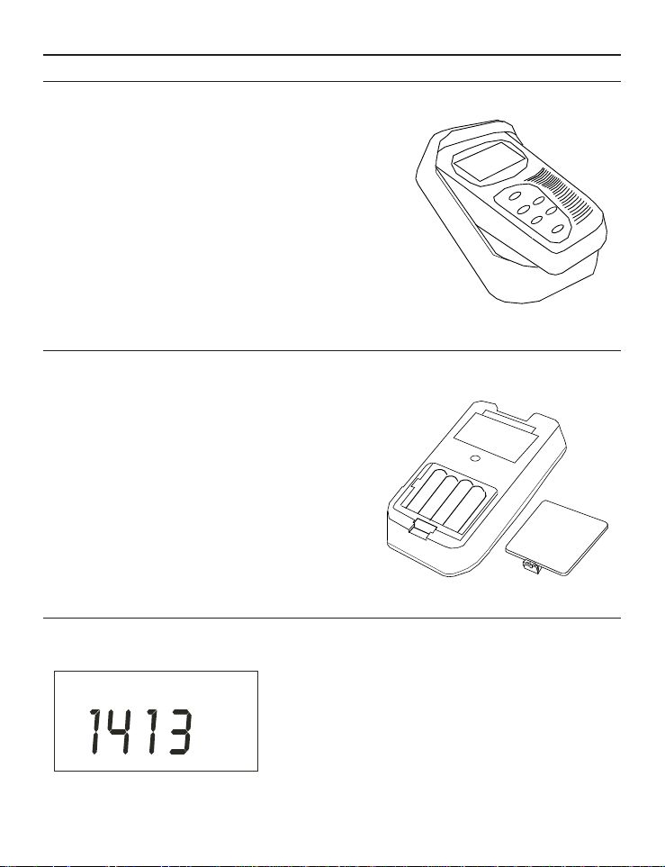
Thank you for purchasing the CON 6 Conductivity Meter or TDS 6 Total
Dissolved Solids Meter. These economy microprocessor-based handheld meters
deliver up to ±0.5% full-scale accuracy. It has a large custom LCD (Liquid
Crystal Display) for clear and easy reading.
The CON 6 measures Conductivity (µS/mS) and Temperature (°C) while the
TDS 6 measures Total Dissolved Solids (TDS) and Temperature (°C). These
sturdy meters measure up to 5 different ranges with auto-ranging capabilities
that that will switch automatically to the appropriate measuring range.
The meters include a conductivity electrode (cell constant K = 1.0) with
built-in temperature sensor, a rubber boot, 4 alkaline “AAA” batteries, and an
instruction manual.
Read the manual thoroughly before operating the meter.
To order other accessories and buffer standard solutions, refer to the
Accessories Section for more information.
5
Page 6
mS
ON
OFF
HOLD
ENTER
CAL
MODE
CON 6
Conductivity/ Meter
C
°
6
Page 7
DISPLAY & KEYPAD FUNCTIONS
pptm
HO LO
%
m
S
µ
1
2
3
4
5
67
C°
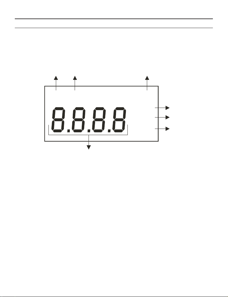
Display
The meter has a large custom LCD that consists of 4-digit segments and
operation annunciators for uS/mS for the CON 6 meter, or ppm/ppt for the
TDS 6 meter, and °C (Temperature). Other annunciators include “HO”
(when the HOLD function is activated) and “LO” (low battery condition).
See Figure below.
LCD and Customized Annunciators for CON 6/TDS 6 meters
1. Primary display
2. Parts Per Million (ppm) or Parts Per Thousand (ppt)
indicator - TDS 6 meter only.
3. milli-Siemens/cm (mS) or micro-Siemens/cm (µS)
4. Temperature indicator
5. Percentage indicator for Temperature Coefficient.
6. Low battery indicator.
7. Hold (freezed) reading indicator.
indicator - CON 6 meter only.
7
Page 8
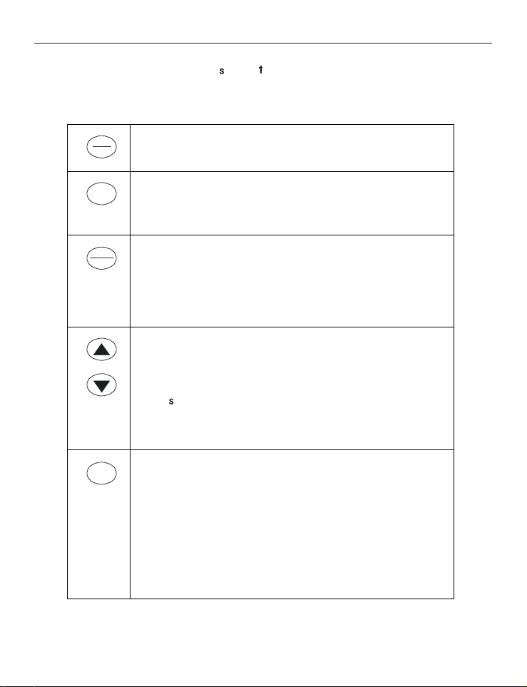
Keypad
ON
OFF
CAL
HOLD
ENTER
MODE
The CON 6 /TDS 6 meter has 6 buttons on the splash-proof keypad; ON/OFF,
HOLD/ENTER, CAL, MODE, and question buttons. Some buttons have
several functions depending on the mode of operation.
Powers on and shuts off the meter. Goes directly
into the measurement mode when the meter is
turned on.
Enters into the calibration mode for
Conductivity/TDS and Temperature.
To abort calibration or set-up mode without
confirming any set value.
HOLD: Freezes the measured reading. To activate,
press HOLD button while in measurement mode. To
release, press HOLD button again.
ENTER: Press to confirm values in the calibration
mode, and to confirm selections in the SET-UP
mode.
In Calibration Mode: Press to scroll through
calibration values.
In Set-up Mode: Press to scroll through the set-up
sub-group programs.
Press button during conductivity measurement
mode to activate manual ranging function. Each
button press will move to a higher conductivity
range.
Selects measurement mode for Conductivity/TDS
and Temperature.
Pressed together with ON/OFF button to go to the
SET-UP mode. This allows customization of meter
preferences such as selecting the electrode cell
constant, normalization temperature, temperature
coefficient factor, TDS factor (for TDS 6), automatic
calibration (CON 6 only) or manual calibration,
single-point or multi-point calibrations, and to reset
meter to factory default.
8
Page 9
PREPARATION
LO
S
µ
Inserting & Removing Rubber Boot
To insert the meter into the rubber boot, slide the top of the meter into the
rubber boot before pushing the bottom edges of
meter down to set it into position. Lift up the
stand at the back of meter for bench top
applications if necessary.
To remove the meter from the rubber boot, first
push the bottom edge of the meter out of the
boot. Ensure that the electrode or temperature
probe cables are not connected.
Inserting the Batteries
The battery compartment is found at the back of instrument as shown. To
open the battery compartment:
1. Remove the rubber boot. Open the
battery compartment. Push in the
direction of arrow and lift up the cover.
2. Insert four AAA batteries. Note the
polarity of battery before inserting into
position.
3. Replace the cover. Press down until it
clicks. Replace the rubber boot.
Battery Replacement
A “LO” annunciator in the LCD will indicate when the battery power is
running low. See Figure below. Replace the
batteries with the same type as recommended
by the manufacturer as soon as possible.
“LO” Battery Condition
Caution: Turn the meter off meter when changing the batteries.
9
Page 10
Conductivity Electrode Information
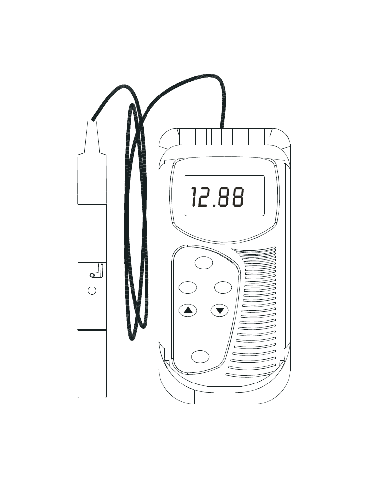
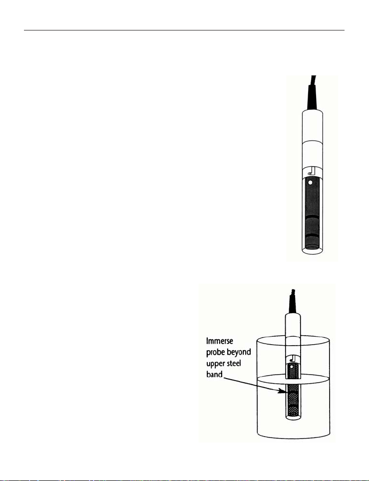
The CON 6/TDS 6 hand-held meter is supplied with a conductivity/TDS
electrode with a BNC connector. This conductivity/TDS electrode comes with
Stainless Steel rings, a cell constant of K = 1.0, and a built-in temperature
sensor for Automatic Temperature Compensation (ATC).
The specially designed Ultem-body housing has chemically
resistant properties. It provides fast temperature response and
reduces air entrapment, which makes it easy to obtain
accurate, stable readings.
The durable probe materials include:
1. Polyetherimide (Ultem) – protective probe guard
2. Polybutylterphalate (Valox) – sensor housing
3. Stainless Steel (SS 304) – 2 steel bands
Proper use of the probe is essential to ensure that the optimum
measurement is taken in the shortest amount of time.
The protective plastic probe guard is removable for simple
periodic maintenance but it must be kept intact during
measurement and calibration.
Always immerse the probe beyond upper steel band.
NOTE:
1. DO NOT remove the protective
probe guard during measurement
and calibration. It will affect the
results.
2. DO NOT submerge the probe
above the protective guard. The
cable can be submerged for brief
periods of time, but not
continuously.
See – “Probe Care and Maintenance”
for more information.
10
Page 11
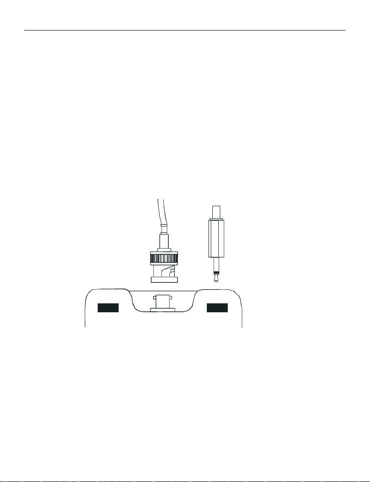
Connecting the Probe to the Meter
BNC connector for
conductivity probe
Phono jack for
Temperature probe
1. To connect the electrode to the meter, align the connector slots with the
posts of the meter socket and rotate the connector clockwise until it locks.
2. To remove, rotate the connector in a counter-clockwise direction until it
unlocks, and slide the connector off the socket.
3. Insert the mini phono jack on the temperature sensor into the socket on
the meter as shown below.
4. Unplug the phono jack when not in use or when measuring Conductivity
or TDS without any temperature compensation (see Manual Temperature
Compensation).
CAUTION: Do not pull on or force the probe cord or the probe wires might
disconnect.
NOTE: Keep connectors clean. Do not touch connectors with soiled hands.
Connection for Conductivity & Temperature Probes
11
Page 12
Turning the Meter On
Measurement Mode
m
S
µ
C°
%
pptmV
pH %MINMAXLOHO
FC°°
m
S
µS
µ
ON
OFF
Measurement Mode
C°
%
ON
OFF
ppm
pptmV
pH %MINMAXLOHO
FC°°
m
S
µ
pptm
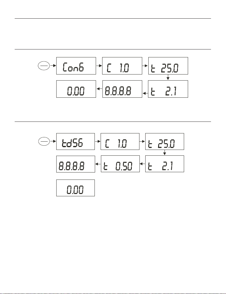
When the meter is turned on, it will go through a series of displays that show
the set-up parameters.
For CON 6
For TDS 6
Press ON/OFF button to turn on the meter.
1. First screen shows [Con 6] (or [tdS 6]) to identify the meter.
2. Second screen shows [C 1.0] which is the conductivity cell constant, k.
Cell constants of 0.1, 1.0 or 10.0 can be selected. Refer to Section on
Advance Set-up. Default value is k=1.0.
3. Third screen shows [t 25.0 °C] which is the Normalization Temperature.
Normalization Temperatures of 25 °C or 20 °C may be selected. Refer to
Section on Advance Set-up. Default value is 25 °C.
12
Page 13
4. Fourth screen shows [t 2.1%] which is the Temperature Coefficient. The
Annunciator
MODE
S
µ
C°
meter can be customized with different Temperature Coefficient values
from 0.0 to 3.0 %/°C in the Advance Set-up mode. Default value is 2.1
%/°C.
5. All LCD segments will light up for 2 seconds, and then advance into the
measurement mode.
6. The meter is ready to measure conductivity or TDS.
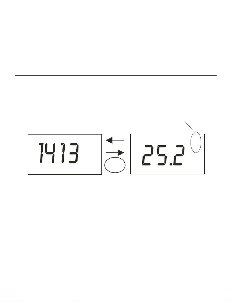
Change Conductivity/ TDS óTemperature Measurement Mode
To switch between the Conductivity/TDS measurement mode and
Temperature measurement mode, press the MODE button.
The customized annunciator will indicate the measurement parameter.
13
Page 14

CALIBRATION
Important Information on Meter Calibration
The meter has five measuring ranges. The meter can be calibrated at one po
int in each of the five measuring ranges. If measurements are being taken in
more than one range, each of the ranges were measurements are being made
must be calibrated.
The following table lists the corresponding conductivity and TDS ranges. Each
range should be calibrated with a solution that falls between the values in the
“recommended calibration solution range” column.
Conductivity
Range
Recommended
Calibration
Solution Range
TDS Range Recommended
Calibration
Solution Range
0.00 to 20.00 µS 6.00 to 17.00 µS 0.00 to 10.00 ppm 3.00 to 8.50 ppm
0.0 to 200.0 µS 60.0 to 170.0 µS 10.0 to 100.0 ppm 30.0 to 85.0 ppm
0 to 2000 µS 600 to 1700 µS 100 to 1000 ppm 300 to 850 ppm
0.00 to 20.00 mS 6.00 to 17.00 mS 1.00 to 10.00 ppt 3.00 to 8.50 ppt
0.0 to 200.0 mS 60.0 to 170.0 mS 10.0 to 200 ppt 30.0 to 170 ppt
When the meter is recalibrated, the old calibrations are replaced on a range by
range basis. For example, if the conductivity meter was previously calibrated at
1413 µS in the 0 to 2000 µS range and it is recalibrated at 1500 µS (also in the
0 to 2000 µS range), the meter will replace the old calibration data (1413 µS)
with the new calibration data (1500 µS ) for that range. The meter will retain
all calibration data in the other ranges.
To completely recalibrate the meter, or when a probe is replaced, it is best to
clear all calibration data. To erase all the old conductivity or TDS calibration
data completely, see – Restore Factory Default Values.
14
Page 15

Preparing the Meter for Calibration
Before starting calibration, be sure the meter is in the correct measurement
mode.
For best results, select a standard value close to the value of the sample that is
being measured. Alternatively use a calibration solution value that is
approximately 2/3 the full-scale value of the measurement range that is being
used. For example, in the 0 to 2000 µS conductivity range, use a 1413 µS
solution for calibration.
Calibrate all measurement ranges to ensure the highest accuracy throughout
the entire measurement range. Note that the CON 6/TDS 6 meter will not
accept calibration values less than 40 µS/cm (20 ppm). All new calibration
values will automatically override existing data.
If solutions with Conductivity lower than 100 µS/cm, or TDS lower than 50
ppm, are being measured the meter should be calibrated at least once a week
for optimum accuracy. If measurements are in the mid-ranges, and the probe is
washed with deionized water and stored dry, the meter can be calibrated once a
month. If measurements are taken at extreme temperatures, the meter should
be calibrated at least once a week.
Fresh conductivity standard solutions should be used during calibration. Do
not reuse standard solutions. They could be contaminated and affect the
calibration and accuracy of the measurements. Store solutions in a dry and cool
environment if possible.
Always rinse the probe with either deionized water or rinse solution before and
after each calibration/sample measurement to avoid cross-contamination. For
details refer to Probe Care and Maintenance.
NOTE: These meters are factory set to a temperature coefficient of 2.1% per
°C. For most applications this will provide good results.
To set the temperature coefficient to different value, see Temperature
Coefficient.
Also, see Appendix 3 - Calculating the Temperature Coefficient to determine
the appropriate temperature coefficient for any solution.
NOTE: The factory default value for normalization temperature is 25 °C. If a
value other than 25 °C is needed, see Normalization Temperature.
15
Page 16

Selection of Automatic or Manual Calibration
This meter is capable of performing either automatic (CON 6 only) or manual
calibration.
In the automatic calibration mode, the meter (CON 6 only) automatically
detects and verifies the appropriate known calibration standards solutions
being calibrated before accepting these particular calibration standards as one
of the calibration values in a specific measurement range. This automatic
calibration mode makes the manual calibration procedure unnecessary.
The calibration standards used for automatic calibration are:
Meter Normalization
Calibration Standards (Range)
Temperature
CON 6 25 °C
1. 84 µS (for 0 – 200 µS/cm)
2. 1413 µS (for 0 – 2000 µS/cm)
3. 12.88 mS (for 0.00 – 20.00 mS/cm)
4. 111.8 mS (for 0.0 – 200.0 mS/cm)
20 °C
1. 76 µS (for 0 – 200 µS/cm)
2. 1278 µS (for 0 – 2000 µS/cm)
3. 11.67 mS (for 0.00 – 20.00 mS/cm)
4. 102.1 mS (for 0.0 – 200.0 mS/cm)
Table 1: Conductivity Calibration Standards for Automatic calibration.
In the manual calibration, non-standard calibration values can be used for
calibration. The appropriate values can be manually input as the desired
calibration standards in each specific range. This is useful in situations with
customized calibration standards that are unique to an application.
To select Automatic or Manual Calibration settings, refer to Automatic
Calibration for more information.
16
Page 17

Automatic Calibration (Conductivity)
mS
mS
mS
mS
CAL
HOLD
ENTER
Measurement Mode
In the Automatic Calibration mode, the meter is capable of accepting a
single-point calibration or up to 4 points for multi-point calibration with the
maximum of 1 point per specific measurement range. For the automatic
calibration standard values refer to Table 1.
1. If necessary, press MODE button to select the
conductivity mode.
2. Rinse the probe thoroughly with deionized water or
a rinse solution, then rinse with a small amount of
calibration standard.
NOTE: For Automatic Calibration one of the
calibration standards listed in Table 1 must be used.
3. Dip the probe into the calibration standard.
Immerse the probe tip beyond the upper steel band .
Gently stir the sample with the probe to create a
homogeneous sample. Allow time for the reading to
stabilize.
4. Press CAL button to enter the conductivity
calibration mode. The [CA] indicator will appear for
1.5 seconds, and a value will appear flashing.
NOTE: To exit calibration without confirmation,
press CAL button again to go back to measurement
mode.
5. Wait for the value to stabilize and press ENTER
button. The calibration standard value will appear
for 3 seconds. If the calibration has been successfully
performed, [donE] will be displayed for about 3
seconds, and the meter will return to the
measurement mode.
6. To perform the next point calibration in the
multi-point calibration, repeat steps 1-5 until all
points have been calibrated.
IMPORTANT NOTES:
1. The meter allows a tolerance range of ±40% of the
calibration standard. An error message “Err 1” will be displayed for 3
seconds if an attempt is made to calibrate with a solution with a value
outside of the tolerance range.
For instance: For 1413 µS conductivity calibration standard, 40% tolerance
is from 848 µS to 1978 µS.
17
Page 18
2. If the temperature (t °C) of the conductivity calibration solution is below 0
mS
mS
mS
mS
CAL
HOLD
ENTER
Measurement Mode
°C or above 50 °C (0°C<t°C>50°C), an error message “Err 2” will be
displayed when performing the auto calibration, and meter will return to
measurement mode.
3. All new calibration data will over-ride existing stored calibration data for
each measuring range calibrated.
4. It is important to use fresh conductivity calibration standards.
5. Low conductivity standard solutions (less than 20 µS /cm) can become
contaminated as soon as they are exposed to the air. Exercise caution
during calibration in the first measurement range (0.00 to 20.0 µS /cm).
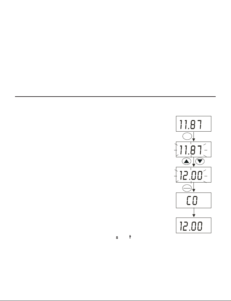
Manual Calibration (Conductivity or TDS)
In Manual Calibration mode (see page 23) the meter can be calibrated with
customized conductivity calibration standards that are
specific to a particular application. The following example
shows the calibration sequence of a 12.00 mS conductivity
calibration standard.
This procedure is for the CON 6 and TDS 6 meters.
1. If necessary, press the MODE button to select the
conductivity mode.
2. Rinse the probe thoroughly with deionized water or a
rinse solution, then rinse with a small amount of
calibration standard.
3. Dip the probe into the calibration standard. Immerse
the probe tip beyond the upper steel band. Gently stir
the sample with the probe to create a homogeneous
sample. Allow time for the reading to stabilize.
4. Press CAL button to enter conductivity calibration
mode. The [CA] indicator will appear for 1.5 seconds,
and a value will appear flashing.
NOTE: To exit calibration without confirmation, press
CAL button again to go back to measurement mode.
5. Wait for the value to stabilize. Press or button and
adjust the value to the calibration standard used.
6. Press the ENTER button. The [CO] indicator will appear for 1.5 seconds,
and the calibration has been successfully performed. The meter will return
to the measurement mode.
7. To perform the next point calibration in the multi-point calibration for the
next range, repeat steps 1-6 until all points have been calibrated.
18
Page 19

Temperature Calibration
The conductivity electrode has a built-in temperature sensor for ATC. The
temperature sensor is factory calibrated to the meter. Calibrate the sensor only
if it is suspected that temperature errors that may have occurred over a long
period of time or if the probe is a replacement probe.
1. Make sure that the phono jack (for temperature measurement) is properly
connected to the meter.
2. Turn on the meter and if necessary, press the MODE button to select the
temperature measurement mode.
3. Press CAL button to start temperature calibration process.
4. Dip the probe into a solution with known temperature (for example, a
temperature bath). Allow time for the temperature to stabilize.
5. After the value has stabilized, press question or button and adjust the
value to the solution temperature.
6. Press the ENTER button. The [CO] indicator will appear for 1.5 seconds,
and the reading will stop flashing. The temperature calibration has been
successfully performed. The meter will return to the measurement mode.
NOTE: To exit calibration without confirmation, press CAL button again to
go back to measurement mode.
NOTE: The temperature reading can be offset up to ±5 °C from the original
(default) reading.
19
Page 20

MEASUREMENT
C°
C°
C°
HOLD
ENTER
°C
CAL
The CON 6/TDS 6 meter is capable of taking measurements with automatic
temperature compensation or manual temperature compensation.
With Automatic Temperature Compensation (ATC)
For ATC, make sure the phono jack of the probe is securely connected to the
meter.
The conductivity/TDS reading displayed will be compensated for according to
the normalization temperature (20 °C or 25 °C) selected. See Normalization
Temperature.
Without ATC (Manual Temperature Compensation)
For manual temperature compensation, unplug the probe phono jack (not
BNC) from the meter.
To use manual temperature compensation, enter the temperature value of the
process into the meter. The meter will compensate the
result to this temperature. Any temperature between 0
and 50 °C (32 to 122 °F) can be selected. The default
value is 25 °C.
1. Make sure that the phono jack (for temperature
measurement) is disconnected from the meter.
2. Turn on the meter and if necessary, press the MODE
button to select the temperature measurement mode.
3. Press CAL button to start the temperature calibration
process.
4. “CA” will appear momentarily and the temperature
value will start flashing.
5. Check the temperature of the sample using an
accurate thermometer. Wait for the value to stabilize.
Press or button and adjust the value on the
display to match the value on the reference
thermometer.
6. Press the ENTER button. The [CO] indicator will
appear for 1.5 seconds, and the reading will stop
flashing. The temperature calibration has been
successfully performed. The meter will return to the
measurement mode.
20
Page 21

Taking Measurements
1. Rinse the probe with deionized or distilled water before use to remove any
impurities adhering to the probe body. Shake or air dry. To avoid
contamination or dilution of the sample, rinse the probe with a small
volume of the sample liquid.
2. Press ON to turn the meter on.
3. Dip the probe into the sample.
4. Allow time for the reading to stabilize. Note the reading on the display.
NOTE: When dipping the probe into the sample, take care to ensure that the
liquid level is above the upper steel band. Gently stir the sample with the
probe to create a homogenous sample.
Using Manual Ranging Function
By default the meter has auto-ranging ability and will automatically select the
range in which the readings appear.
However, a specific range may be selected. This is achieved by pressing
button successively for each measurement range. The five ranges are:
Conductivity
Range (CON 6)
TDS Range (TDS 6)
(if TDS factor is 0.5)
0 – 20.00 µS/cm 0 – 10.00 ppm
0 – 200.0 µS/cm 0 – 100.0 ppm
0 – 2000 µS/cm 0 – 1000 ppm
0 – 20.00 mS/cm 0 – 10.00 ppt
0 – 200.0 mS/cm 0 – 100 ppt
21
Page 22

NOTE:
S
µ
mSmS
Auto-ra nging Manual r anging: 0 - 2 0.00 uS/cm Manual r anging: 0 - 2 00.0 uS/cm
Manual r anging: 0 - 2 000 uS/cmManual r anging: 0 - 2 0.00 mS/cmManual r anging: 0 - 2 00.0 mS/cm
S
µ
S
µ
S
µ
S
µ
S
µ
HOLD
ENTER
HO
If the value of the solution being measured is higher than the range selected
[Or] will appear on the primary display. Press RANGE until the correct range
is selected.
The meter resets to the Auto-ranging function once it is turned off. The
manual ranging function must be reset each time the meter is turned on.
HOLD Function
The hold feature will freeze the display for a delayed
observation. HOLD can be used any time in
measurement mode.
1. To hold a measurement, press the HOLD button
while in measurement mode. [HO] will appear on the
display.
2. To release the held value, press the HOLD button
again. Continue to take measurements.
NOTE:
The meter will shut off automatically after 20 minutes of nonuse.
If the meter is shut off either automatically or manually, the HOLD value will
be lost.
22
Page 23

ADVANCED SET-UP FUNCTIONS
%
C°
Advanced Set-up Overview
The advanced set-up mode customizes the meter preferences and defaults. To
enter the advanced set-up mode:
1. Make sure that the meter is turned off.
2. Press ON and MODE buttons simultaneously, holding both buttons for 2
seconds. First release ON button first before releasing the MODE button.
3. [StUP] indicator will appear momentarily and [CELC] will appear next.
4. Overviews of the CON 6 and TDS 6 Set-up Menu are as follows.
Enter Set-Up Page.
Select Cell Constant. Choice of k =
0.1, 1.0, and 10.0.
Default value is 1.0.
Select Automatic Calibration. “Yes”
for auto calibration and “no” for
manual calibration.
Default value is “Yes”. (Available in
CON 6 meter only)
Adjust Temperature Coefficient
value from 0.0 to 3.0 %/°C.
Default value is 2.1 %/°C.
Select Normalization Temperature.
Choice of either 20 °C or 25 °C.
Default value is 25 °C.
Adjust TDS factor from 0.4 to 1.0.
Default value is 0.5. (Available in
TDS 6 meter only)
23
Page 24

Select Single Point Calibration.
%
C
°
Meter Off
Press ON/OFF and MODE buttons
simultaneously for 2 seconds, release
ON/OFF button first then release MODE
key button a second later.
A "StUP" indicator will appear for 1.5
seconds before showing the first menu
ON
OFF
MODE
Choice of “Yes” or “No”.
Default value is “Yes”.
User reset to factory defaults.
Choice of “Yes” or “No”.
Default value is “no”.
Overview of Advanced Set-Up
Overview of CON 6 Set-Up Menu
24
Page 25

Overview of TDS 6 Set-Up Menu
%
C°
Meter Off
Press ON/OFF and MODE buttons keys
simultaneously for 2 seconds, release
Release ON/OFF button first then release MODE button
a second later.
A "StUP" indicator will appear for 1.5
seconds before showing the first menu.
ON
OFF
MODE
HOLD
ENTER
Select Cell Constant
It is possible to select a cell constant of K = 1.0, 10, or 0.1.
Use a cell of K = 1.0 for midrange measurements
Use a cell ofK=10forhigh range measurements
(above 20 mS or 10 ppt).
Use a cell of K = 0.1 for low range measurements
(below 20 µS or 10 ppm).
The cell included with the meter has a cell constant
of K = 1.0.
1. Enter Advanced Set up.
2. Press or button until [CELC] appears on the
LCD. Press ENTER button.
3. Press or button to select either “1.0”, “0.1” or
“10.0”. Ensure the cell constant selected correspond
with the conductivity electrode that is being used
with the meter.
4. Press ENTER button to select. The meter will
return to the menu, [CELC].
5. Press or button to move to the next menu or
press CAL to exit to measurement mode.
25
Page 26

Automatic Calibration (for CON 6)
HOLD
ENTER
Press ENTER to confirm selection; or
Press CAL to escape without confirming selection
Press ENTER to confirm selection; or
Press CAL to escape without confirming selection
HOLD
ENTER
The automatic calibration allows the meter to be quickly
calibrated to any of the four widely used conductivity
calibration standards. For a list of calibration standards
refer to Table 1.
In the manual calibration mode, customized conductivity
calibration standard can be used to calibrate this meter.
1. Enter Advanced Set-up.
2. Press or button until [ACAL] appears on the
LCD. Press ENTER button.
3. Press or button to select either [Yes]or[no].
4. Press [ENTER] button to select. The meter will
return to the menu, [ACAL].
5. Press or button to move to the next menu or press CAL to exit to
measurement mode.
Setting the TDS Factor (for TDS 6)
The concentration of salts dissolved in solution increases the conductivity of
that solution. This relationship varies from salt to salt and is roughly linear
over a given range for a given salt. The TDS conversion factor is the number
used by the meter to convert from conductivity to TDS.
To calculate the TDS conversion factor refers to
Appendix 2 – Calculating TDS Conversion Factor.
TDS conversion factors for various types of salts can
also be found in chemical reference books.
The TDS conversion factor can be set between 0.4 and
1.0. The meter default is 0.5.
1. Enter Advanced Set-up.
2. Press or button until [tdS] appears on the LCD.
Press ENTER button.
3. Press or button to select a value between 0.4 to
1.0.
4. Press ENTER button to select. The meter will take
return to the menu, [tdS].
5 .Press or button to move to the next menu or press CAL to exit to the
measurement mode.
26
Page 27

Temperature Coefficient
Press ENTER to confirm selection; or
Press CAL to escape without confirming selection
%
%
%
HOLD
ENTER
Press ENTER to confirm selection; or
Press CAL to escape without confirming selection
C°
C°
C°
HOLD
ENTER
The temperature coefficient is the amount of change in
conductivity per degree of temperature; it is expressed in
percent per °C. Entering the exact temperature
coefficient of the solution being measured will accurately
compensate the temperature for almost any solution. The
temperature coefficient can be set between 0.0 and 3.0 %
per °C. The meter default is 2.1% per °C.
6. Enter Advanced Set-up.
7. Press or button until [t.Co %] appears on the
LCD. Press ENTER button.
8. Press or button to select a value between 0.0 and
3.0.
9. Press ENTER button to select. The meter will return
to the menu, [t.Co %].
Press or button to move to the next menu or press CAL to exit to the
measurement mode.
Normalization Temperature
The meter can be set to normalize the conductivity measurements to a
standard temperature of either 25 °C or 20 °C.
The default value is 25 °C.
1. Enter Advanced Set-up.
2. Press or button until [t.nr °C] appears on the
LCD. Press ENTER button.
3. Press or button to select either [25.0 °C]or[20.0
°C].
4. Press ENTER button to select. The meter will return
to the menu, [t.nr °C].
5. Press or button to move to the next menu or
press CAL to exit to the measurement mode.
27
Page 28

Single-Point Calibration
Press ENTER to confirm selection; or
Press CAL to escape without confirming selection
HOLD
ENTER
Press ENTER to confirm selection; or
Press CAL to escape without confirming selection
HOLD
ENTER
A single-point calibration refers to calibrating at one
conductivity value that will be used for all 5 conductivity
ranges.
By selecting [no] to single-point calibration, a calibration
for each conductivity range can be performed.
1. Enter Advanced Set-up.
2. Press or button until [S.P.CA] appears on the
LCD. Press ENTER button.
3. Press or button to select either [Yes]orno].
4. Press ENTER button to select. The meter will return
to the menu, [S.P.CA].
5. Press or button to move to the next menu or
press CAL to exit to the measurement mode.
Restore Factory Default Values
This function allows all parameters to be reset to the factory default settings.
This clears all calibration data and any other set-up
functions that may have been changed.
IMPORTANT: Once activated the meter settings and
calibration data will be erased. Always exercise caution.
Meter reset is not reversible.
1. Enter Advanced Set-up.
2. Press or button until [UrSt] appears on the LCD.
Press ENTER button.
3. Press or button to select either [Yes]or[no].
4. Press ENTER button to select.
5. The meter will return to the measurement mode after
the turn-on initialization.
28
Page 29

PROBE CARE AND MAINTENANCE
Keep the conductivity probe clean. Rinse the probe twice before using. Gently
swirl the probe in the solution while taking readings. Do not immerse the
probe in oily solutions.
For best accuracy, soak a dry probe for at least 5 to 10 minutes or longer before
calibration.
The conductivity probe included with the meter features a removable probe
guard to make cleaning easy.
To remove probe guard:
1. Grip the yellow probe guard and twist clockwise.
The locking notch will release.
2. Slide the probe guard off the end of the probe.
Clean the electrode thoroughly by stirring it in a mild
detergent bath or isopropyl alcohol. Wipe the probe
with a soft tissue paper. Rinse thoroughly in tap water
and then in deionized water. Recalibrate the meter after
cleaning the probe.
NOTE: Remember to re-attach the probe guard prior to
taking readings. Failure to do so could result in
erroneous readings.
Rinse the probe with deionized or tap water before
storing. Never scratch the bands with a hard substance.
Do not strike the probe against any hard surface.
29
Page 30

TROUBLESHOOTING GUIDE
Problem Cause Solution
Power on but
no display
a) Batteries not in
place
b) Batteries not in
correct polarity (+ and
– position)
a) Check that batteries
are in place and
making good contact.
b) Reinsert batteries
with correct polarity.
Unstable
readings
Slow
response
c) Weak batteries
a) Air bubbles in probe
c) Replace batteries.
a) Tap probe to remove
bubbles.
b) Dirty probe
b) Clean the probe and
c) Probe not deep
recalibrate.
enough in sample
c) Make sure sample
d) External noise
pickup or induction
entirely covers the
probe sensors.
caused by nearby
electric motor
d) Move or turn off
interfering motor.
e) Broken probe
e) Replace probe.
a) Dirty / Oily probe a) Clean probe. See
“Probe Care &
Maintenance”.
30
Page 31

ERROR MESSAGES
LCD Display Indicates Cause Solution
“LO”
indicator
appears.
Low battery
level
Need new
batteries or
battery
connection is
bad.
Err 1 Conductivity
calibration
error
Calibration
point is outside
the ±40%
window in the
auto-calibration.
Err 2 Temperature
calibration
error
Auto calibration
is performed
outside the
temperature
range (0 – 50
°C).
Err 3 Conductivity
calibration
error
Calibration
point is within
10% of the
measurement
range in the
manual
calibration
mode.
Clean battery
contacts.
Replace batteries
with fresh ones,
noting polarity.
Check the value
of the
conductivity
calibration
solution.
Turn to manual
calibration mode
and calibrate
again.
If message
persists, return
unit*.
Check the
temperature and
make sure that it
is within the
acceptable range.
If message
persists, return
unit*.
Check the value
of the
conductivity
calibration
solution.
If message
persists, return
unit*.
* See Sections on “Warranty” and “Return of Items”.
31
Page 32

If an error message appears, turning off the meter and
LO
S
µ
turning it on again may eliminate the error message.
Refer to diagram on right.
If error persists, or the meter shows incorrect values,
return the meter.
For a complete diagram of the display see page 3.
SPECIFICATIONS DESCRIPTIONS CON 6 TDS 6
Conductivity Range 0 to 20.00, 200.0,
X
2000 µS/cm;
0 to 20.00,
200.0 mS/cm
Resolution 0.01, 0.1, 1 µS/cm:
0.01, 0.1 ,S/cm
Accuracy ±1% F.S.
TDS Range 0 to 10.00, 10.0 to
100.0, 100 to 1000
ppm;
1.00 to 10.00, 10.00 to
100.0, Up to 200 ppt
depending on the
TDS factor setting.
Resolution 0.01, 0.1, 1 ppm;
XX
0.01, 0.1 ppt
Accuracy
Temperature Range -10.0 to 110.0 °C
±1% F.S. X X
XX
Resolution/Accuracy 0.1 °C / ± 0.5 for °C X
Cell Constant 0.1, 1.0, 10.0
XX
(selectable)
Temperature
Compensation
Automatic / Manual
(from 0 to 50 °C)
XX
X
X
X
X
32
Page 33

SPECIFICATIONS DESCRIPTIONS CON 6 TDS 6
Temperature
0.0 to 3.0% / °C
X
Coefficient
Normalization
Temperature
20.0 °C and 25.0 °C
(selectable)
XX
Conductivity to TDS
0.4 to 1.0
Conversion factor
Number of
calibration points
5: Maximum 1 per
range
Auto- &
Manual-ranging
HOLD Function
Auto Power Off 20 minutes after last
button operation
Inputs BNC for conductivity
and phono jack for
temperature
Display Single Custom LCD
Power Requirements 4 ‘AAA’ Batteries
Battery Life > 100 hours
Dimension / Weight
Meter: 14x7x3.5cm;
200 g
X
XX
XX
XX
XX
X
X
XX
XX
XX
XX
33
Page 34

ACCESSORIES
Replacement Meter and Meter accessories
Item Code
CON 6, portable conductivity meter
complete with conductivity probe of
k=1.0 and case
TDS 6, portable TDS meter complete
with conductivity probe of k=1.0 and
case
Electrode, stainless steel 3 ring,
Ultem body with ATC, BNC plug
(for CON 6), cell constant = 1.0,
x110 mm, 1m cable length
Protective Rubber Boot 5-0040
Calibration Solutions
5-0039-01
5-0037-01
5-0106
84mS, 25 mL
1413mS, 100 mL
6312-G
6354-J
12.88 mS, 25 mL 6317-G
34
Page 35

CONDUCTIVITY THEORY
Conductivity is defined as the ability of a solution to conduct an electrical
current, or the reciprocal of the solution’s ability to resist the current. The
current is conducted by electrically charged particles called ions, which are
present in almost all solutions. Different solutions have different kinds and
amounts of ions. Distilled water has very few ions, and therefore a low
conductivity, while seawater has a large number of ions, and a high
conductivity.
Although a conductivity reading provides an overall measurement of the ionic
strength of a solution, it is not possible to distinguish the specific amounts of
individual ions. For this reason, conductivity is often used to measure the total
dissolved solids (TDS) of a solution. TDS is defined as the amount of solids
that will pass through a 45 micron filter. Rather than filtering a solution, the
TDS can be estimated by multiplying the conductivity measurement by a
predetermined factor. This factor, which is determined gravimetrically, will fall
between 0.55 and 0.9. A commonly used factor is 0.7.
Conductivity is measured using a probe which has two parallel plates separated
by a fixed distance. When a voltage from the meter is applied across the
electrodes, the ions in the solution conduct a current that flows between the
two electrodes. The greater the concentration of ions in the solution, the
larger the current generated and the higher the conductivity. Likewise, the
smaller the concentration of ions, the lower the conductivity. The meter
converts the current measured to a conductivity reading. Conductivity values
are related to the conductance of a solution by the physical dimensions - area
and length — or the cell constant of the measuring electrode. The physical
distance between the plates is also critical, as it effects the strength of the
electric field between the plates. By using cells with defined plate areas and
separation distances, it is possible to standardize conductance measurements.
The relationship between conductance and specific conductivity is:
Specific Conductivity S.C. = (Conductance) (cell constant, k)
= siemens x cm/cm
= siemens/cm
2
where C is the conductance (siemens)
k is the cell constant, length/area or cm/cm
2
Conductivity is measured in microsiemens per centimeter (mS/cm). In waters
of higher conductivity, mS/cm may be multiplied by 1000, giving results as
millisiemens per centimeter (mS/cm). Total dissolved solids are measured in
parts per million (ppm). Therefore:
µS/cm X 0.7 = ppm TDS
35
Page 36

Conductivity measurements are very dependent on temperature. The ability of
the ions to move through the solution, and conduct the current, is related to
the temperature of the solution. As the temperature of the solution rises, the
ions move more quickly through the solution, increasing the conductivity. As
the temperature decreases the ions move more slowly and the conductivity
decreases. Since the conductivity of the same solution can change by as much
as 2 percent per °C, accurate temperature measurements must be made
simultaneously to with the conductivity reading. The CON 6/TDS 6 has a
temperature sensor within the probe that will measure the temperature of the
solution.
To make conductivity readings taken at different times and places comparable,
measurements are often converted to what the conductivity of the solution
would be at 20°Cor25°C. The CON 6/TDS 6 automatically applies this
conversion before displaying a reading.
Because it is a quick, reliable, and inexpensive way of monitoring the ionic
content of a solution, conductivity measurements are widely used in many
areas of water testing from environmental monitoring to municipal water
supplies to many industrial applications.
APPENDIX 1: CALIBRATION TIPS
Only one calibration point is needed to measure solutions throughout the
entire range of the meter. If a range was not calibrated, the meter will
automatically detect the closest range calibrated and use that calibration
information. However, only the ranges that were calibrated will have
maximum accuracy.
If the solutions being measured are near to or greater than 20 mS (10 ppt), or
near to or lower than 100 µS (50 ppm), the meter should be calibrated at least
once a week to get the specified ±1% F.S. accuracy.
If the solutions being measured are in the mid-ranges and the probe was
washed in deionized water and stored dry, the meter should be calibrated at
least once a month.
Wet the probe for 10 minutes before calibrating or taking readings to saturate
the probe surface and minimize drift. If measurements are made at extreme
temperatures, the meter should be calibrated at least once a week.
Use only the conductivity/TDS probe specified for the CON 6/TDS 6 meters.
This probe has a built-in temperature sensor. If a probe without a temperature
sensor is used, the temperature of the solutions must be measured and manually
entered into the meter. (see Manual Temperature Compensation section 5.2)
36
Page 37

APPENDIX 2: CALCULATING The TDS CONVERSION FACTOR
The meter can be calibrated using TDS calibration standard solutions. The
TDS value of the solution at a standard temperature, such as 25 °C, is required.
To determine the conductivity-to-TDS conversion factor use the following
formula:
Factor = Actual TDS ÷ Actual Conductivity @ 25 °C
Definitions:
•Actual TDS: Value from the solution bottle label or as calculated when
prepared with high purity water and precisely weighed salts.
•Actual Conductivity: Value measured using a properly calibrated
Conductivity/Temperature meter.
Both the Actual TDS value and the Actual Conductivity values must be in the
same magnitude of units. For example, if the TDS value is in ppm the
conductivity value must be in µS; if the TDS value is in ppt the conductivity
value must be in mS.
The calculated factor can be checked by multiplying the conductivity reading
by the factor. The result should be the TDS value.
APPENDIX 3: CALCULATING TEMPERATURE COEFFICIENTS
To determine the temperature coefficient of the sample solution:
Where:
tc = Temperature coefficient 25 = 25 °C
C
= Conductivity at Temp 1 CT2= Conductivity at Temp 2
T1
T
= Temp 1 T2= Temp 2
1
NOTE: A controlled temperature water bath is ideal for this procedure.
1. Immerse the probe in the solution and adjust the temperature coefficient to
0% (that is, no compensation) by following instructions as described in
Temperature Coefficient.
37
Page 38

2. Wait for 5 minutes. Note T1and CT1(conductivity at T1).
3. Condition the sample solution and probe to a temperature (T
about 5 °C to 10 °C different from T
C
.
T2
, and note the conductivity reading
1
NOTE: Record the results for future reference. Ideally T
bracket the measurement temperature, and should not differ by more than
) that is
2
and T2should
1
5 °C.
4. Calculate the temperature coefficient of the solution according to the
formula shown above.
5. Enter the calculated temperature coefficient into the meter. Refer to
Temperature Coefficient.
The calculated temperature coefficient will not be applied to all the meter
readings.
WARRANTY
This Instrument is guaranteed to be free from defects in material and
workmanship for a period of three (3) years from the original purchase date.
The probe is guaranteed to be free from defects in material and workmanship
for a period of six (6) months from the original purchase date. In the event
that a defect is found during the warranty time frame, LaMotte Company
agrees that it will be repaired or replaced without charge except for the
transportation costs. This guarantee does not cover batteries.
This product can not be returned without a return authorization number from
LaMotte Company. For warranty support or a Return Authorization Number,
contact LaMotte Company at 1-800-344-3100 or tech@lamotte.com.
Limitations
This guarantee is void under the following circumstances:
• Damage due to operator negligence, misuse, accident or improper
application.
• Damage or alterations from attempted repairs by an unauthorized
(non-LaMotte) service.
• Damage due to improper power source, AC adapter or battery.
• Damage caused by acts of God or natural disaster.
• Damage occurred while in transit with a shipping carrier.
LaMotte Company will service and repair out-of-warranty products at a
nominal charge..
38
Page 39

Packaging and Delivery
Experienced personnel at LaMotte Company assure adequate protection
against normal hazards encountered during shipping. After the product leaves
the manufacturer, the transporter assures all responsibility for its safe delivery.
Damage claims must be filed immediately with the transporter to receive
compensation for damaged good
RETURN OF ITEMS
Should it be necessary to return the meter for repair or servicing, pack the
meter carefully in a suitable container with adequate packing material. A
return authorization number must be obtained from LaMotte Company by
calling 1-800-344-3100, faxing 1-410-778-6394, or emailing
tech@lamotte.com. Often a problem can be resolved over the phone or by
email. If a return of the meter is necessary, attach a letter with the return
authorization number, meter serial number, a brief description of problem and
contact information including phone & FAX numbers to the shipping carton.
This information will enable the service department to make the required
repairs more efficiently.
39
Page 40

LaMOTTE COMPANY
Helping People Solve Analytical Challenges®
PO Box 329 • Chestertown • Maryland • 21620 • USA
800-344-3100 • 410-778-3100 • Fax 410-778-6394
Visit us on the web at www.lamotte.com
626094-26/28 - 09/08
 Loading...