

Page 1
TC-3000e • Code 1964-EPA
TC-3000i • Code 1964-ISO
Version 1.5 • Code 1964-MN • 11-27-07
Page 2
WARNING! This set contains chemicals
WARNING! This set contains chemicals
that may be harmful if misused. Read
that may be harmful if misused. Read
cautions on individual containers
cautions on individual containers
carefully. Not to be used by children
carefully. Not to be used by children
except under adult supervision.
except under adult supervision.
Page 3

CONTENTS
Introduction
Turbidity
WhatisTurbidity?.............................5
HowisTurbidityMeasured?........................5
TakingTurbidityWaterSamples.......................7
Chlorine
WhatisChlorine?.............................7
HowisChlorineMeasured?........................7
TakingChlorineWaterSamples ......................8
Color
WhatisColor?..............................8
HowisColorMeasured? .........................8
SampleDilutionTechniques...........................9
Options and Set Up
FactoryDefaultSettings ............................10
ResettoFactoryDefaultSettings.........................10
Turbidity
SelectingTurbidityUnits..........................10
SelectingaTurbidityCalibrationCurve...................11
Chlorine
SelectingChlorineUnits .........................13
SelectingaChlorineReagentSystem ...................14
Averaging.................................15-16
SettingDate&Time............................16-17
SelectingaLanguage.............................18
SettingAutoShutdown.............................19
Data Logging .............................20-21
Tube Positioning Ring...........................22
Analysis and Calibration
Turbidity
Analysis...............................23-25
DilutionProcedures ...........................26
PreparationofTurbidity-FreeWater...................26-27
TurbidityStandards............................28
CalibrationProcedure.........................28-32
TestingTips .............................32-33
Chlorine
Analysis.................................33
TabletDPDReagents.........................33-38
LiquidDPDReagents.........................39-44
CONTENTS 3
Page 4

Dilutionprocedures ...........................45
StandardSolutions..........................45-48
CalibrationProcedure-Tablets ....................48-51
CalibrationProcedure-Liquid.....................48-51
TestingTips...............................52
Color
Analysis...............................52-54
DilutionProcedures ...........................54
StandardSolutions............................54
CalibrationProcedure.........................55-58
TestingTips...............................58
Troubleshooting Guide..........................59
General Operating Information
Overview.................................60-61
TheKeypad..................................62
TheDisplay&Menus............................63-65
Tube ....................................65
PC Link ..................................66
Output....................................66
ComputerConnection.............................66
Battery Operation
ReplacingtheBattery..............................66
Maintenance
Cleaning...................................66
MeterDisposal................................67
Repairs....................................67
General Information
PackagingandDelivery ............................68
GeneralPrecautions..............................68
SafetyPrecautions...............................68
Limits of Liability ................................68
Specifications...............................69-70
StatisticalandTechnicalDefinitionsRelatedtoProductSpecifications........71
ContentsandAccessories ...........................72
EPACompliance ...............................73
ISOCompliance ...............................73
CECompliance................................73
Warranty...................................73
4 CONTENTS
Page 5

INTRODUCTION
TURBIDITY
What is Turbidity?
Turbidity is an aggregate property of the solution, water in most cases. Turbidity is not
specific to the types of particles in the water. They could be suspended or colloidal
matter and they can be inorganic, organic or biological. At high concentrations
turbidity is perceived as cloudiness or haze or an absence of clarity in the water.
Turbidity is an optical property that results when light passing through a liquid sample
is scattered. The scattering of light results in a change in the direction of the light
passing through the liquid. This is most often caused when the light strikes particles in
solution and is scattered backward, sideways and forward. If the turbidity is low much
of the light will continue in the original direction. Light scattered by the particles allows
the particle to be ”seen” or detected in solution. Just as sunlight passing through a
window is scattered by dust particles in the air, allowing them to be seen.
In the past 10 years, turbidity has become more than just a measure of water clarity.
Because of the emergence of pathogens such as Cryptosporidium and Giardia,
turbidity now holds the key to assuring proper water filtration. In 1998, the EPA
published the IESWTR (interim enhanced surface water treatment rule) mandating
turbidities in combined filter effluent to read at or below 0.3 NTU. By doing so, the
EPA hoped to achieve a 2 log (99%) removal of Cryptosporidium. There is presently
consideration to lower this to 0.1 NTU. The trend has been to check the calibration of
on-line turbidimeters with hand-held field units. The optical design and low detection
limit of the TC-3000 allow very accurate readings for such calibrations.
The meter also allows the user to choose the units of measure for expressing turbidity.
While nephelometric turbidity unit (NTU) has been the standard for years, FNU
(formazin nephelometric unit) and FAU (formazin attenuation unit) are now being used
in ISO 7027 units. American Society of Brewing Chemists (ASBC) units and European
Brewery Convention (EBC) units allow the brewing industry to check process waters.
How is Turbidity Measured?
Scattered Turbidity 90°
and Color Detector
Chlorine
Detector
Turbidity Light
Direct
Turbidity
Detector
Source
IR LED 860nm: 3000i
Tungsten Lamp: 3000e
and stabilization detector
Chlorine LED 525nm
and stabilization detector
Color UV LED 375nm
and stabilization detector
INTRODUCTION 5
Page 6

Turbidity is measured by detecting and quantifying the scattering of light in water
(solution). Turbidity can be measured in many ways. There are visual methods and
instrumental methods. Visual methods are more suitable for samples with high
turbidity. Instrumental methods can be used on samples with both high and low levels
of turbidity.
Two visual methods are the Secchi Disk method and the Jackson Candle method. The
Secchi Disk method is often used in natural waters. A black and white Secchi Disk is
lowered into the water until it can no longer be seen. It is then raised until it can be
seen again. The average of these two distances is known as the “Secchi Depth”. The
Jackson Candle method uses a long glass tube over a standard candle. Water is
added or removed from the tube until the candle flame becomes indistinct. The depth
of the water measured with a calibrated scale is reported as Jackson Turbidity Units
(JTU). The lowest turbidity that can be determined with this method is about 25 NTU.
There are two common methods for instruments to measure turbidity. Instruments can
measure the attenuation of a light beam passing through a sample and they can
measure the scattered light from a light beam passing through a sample. In the
attenuation method, the intensity of a light beam passing through turbid sample is
compared with the intensity passing through a turbidity-free sample at 180° from the
light source. This method is good for highly turbid samples. The most common
instrument for measuring scatter light in a water sample is a nephelometer. A
nephelometer measures light scattered at 90° to the light beam. Light scattered at
other angles may also be measured, but the 90° angle defines a nephelometric
measurement. The light source for nephelometric measurements can be one of two
types to meet EPA or ISO specifications. The EPA specifies a tungsten lamp with a color
temperature of 2,200–3,000 K. The units of measurement for the EPA method are
nephelometric turbidity units (NTU). The ISO specifies a light emitting diode (LED) with
a wavelength of 860 nm and a spectral bandwidth less than or equal to 60 nm. The
units of measurement for the ISO method are formazin nephelometric units (FNU).
The TC-3000e meets the EPA specification and the TC-3000i meets the ISO
specification. The nephelometric method is most useful for low turbidity.
The TC-3000 is a nephelometer that is capable of measuring turbidity by both the
attenuation method and the nephelometric method. It uses a detector placed at 180°
to the light source for the attenuation method. It uses a detector placed at 90° to the
light source for the Nephelometric method. The TC-3000 also has a third detector that
monitors the intensity of the light source. It uses this detector to improve instrumental
stability and minimize calibration drift. The TC-3000 also has a signal averaging
option to improve the stability of readings on low turbidity samples.
The TC-3000 has two different turbidity calibrations, formazin and Japan Standard.
The formazin calibration is the EPA and ISO approved method of calibrating
nephelometers. This calibration can be used with user prepared formazin standards or
commercially purchased formazin standards. LaMotte Company approved AMCO
TM
standards labeled for use with the TC-3000 can also be used with the formazin
calibration. Stablcal
â
standards below 50 NTU should not be used to calibrate the
TC-3000.
The Japan Standard calibration is a calibration for a Japanese Water Works standard.
It is based on Japanese formulated polystyrene turbidity standards. This calibration
should only be use to meet Japanese Water Works requirements. The Japanese
polystyrene standards can only be purchased in Japan. Formazin, AMCO and
Stablcal
6 TURBIDITY
â
standards cannot be used with this calibration.
Page 7

T AKING TURBIDITY WATER SAMPLES
Clean plastic or glass containers may be used for turbidity samples. Ideally, samples
should be tested soon after collection and at the same temperature as when collected.
CHLORINE
What is Chlorine?
Chlorine is added to water systems to sanitize the water. There are various forms of
chlorine that are added to water. These can be gas, liquid (commonly called bleach or
sodium hypochlorite), calcium hypochlorite mixtures, stabilized chlorine products and
as chlorine generated using salt. When these forms of chlorine are added, they react
with water to form free chlorine, hypochlorous acid. If free chlorine reacts with
ammonia, it will form various types of combined chlorine (chloramines). Depending on
the chlorine to ammonia ratio, these can be mono, di or tri chloramines.
Because free chlorine can react with precursors in the water to form carcinogenic
trihalomethanes (THMs), many water systems have switched to chloramines. In these
systems, free chlorine and ammonia are added together and controlled to form
monochloramine. Although not as active a sanitizer as free chlorine, chloramine is less
likely to form THMs. Since it is a slower sanitizer, the concentration of chloramine in
water is higher than the concentration of free chlorine in water distribution systems.
The present EPA limit of chlorine in water systems is 4.0 ppm. The amount of chlorine
used to process waste may be higher than this.
Many states also establish limits on the amount of chlorine that can be discharged into
a body of water after waste processing. These usually are less than 0.1 ppm. The low
detection limit of the TC-3000 makes it ideal for such measurements. Because of its
wide range, the TC-3000 can be used to measure the water used in the wastewater
process, in a distribution system and for many low level discharge requirements.
How is Chlorine Measured?
The most common methods for measuring chlorine are colorimetric methods. In
colorimetric methods, chlorine reacts with reagents added to a water sample. The
reaction of the chlorine with the reagents produces a color. The intensity of the color
produced is proportional to the concentration of chlorine in the sample. The intensity
of the color can be measured by visual comparison with a calibrated color chart or
othere types of visual color comparators. Visual methods suffer due to the subjective
observations of the person judging the colors.
The TC-3000 uses EPA approved DPD reagents to react with chlorine. In the absence
of iodide, free available chlorine reacts instantly with DPD to produce a pink color.
Subsequent addition of potassium iodide (DPD 3) causes a reaction with combined
form of chlorine. The TC-3000 electronically measures the color produced in these
reactions in comparison to a colorless water sample. First it measures the intensity of a
light beam passing through a clear colorless sample, the blank. Then it measures the
intensity of light passing through the pink reacted sample. The TC-3000 uses the ratio
of these two measurements to calculate the concentration of chlorine and displays the
result. The TC-3000 uses the EPA approved wavelength of 525 nm, to make these
measurements.
CHLORINE 7
Page 8

Taking Chlorine Water Samples
Chlorine solutions are not stable and should be analyzed immediately. Samples may
be collected in glass. Amber or opaque bottles are recommended since exposure to
sunlight or agitation will decrease chlorine concentrations. It is best to fill bottles
completely to assure there is no air in the container. If sampling from a tap, allow the
water to run for a minute to assure a proper sample.
COLOR
What is Color?
Many different dissolved or suspended materials contribute to the color of water. These
can include industrial wastes, plant materials, metals and plankton. There are two
terms used to define color. If one examines a water sample straight from a water
source, the color of the water is its apparent color. To ascertain the color of the water
without the contribution of suspended substances and is called true color. True color
can increase after precipitation, and decrease in drier weather.
Some bodies of water can change color quickly, depending on the runoff conditions
and plant life around them. Wind can also stir up substances more in shallower bodies
of water causing quick color change. Major contributors are tannins, hemic acids, and
inorganic minerals. Color can be critical, since as the color increases, the amount of
light that penetrates the water decreases, and thus submerged plant life, that depend
on this light for photosynthesis, will decrease.
How is Color Measured?
Since most natural waters have color that is similar to a solution of chloroplatinate and
cobalt, the APHA specifies the use of dilute chloroplatinate/cobalt color standards to
define color values. In the APHA method, the color of a water sample is compared
visually to 6 to 9 chloroplatinate/cobalt standards. However, visual methods suffer due
to the subjective observations of the person judging the colors. To eliminate this source
of error, color can be measured electonically with a spectrophotometer, or colorimeter
liekt the TC-3000.
The TC-3000 is calibrated with APHA color standards at 375 nm. This wavelength
was found to give the greatest sensitivity with chloroplatinate/cobalt color standards,
thus most natural waters. The meter electronically measures color in comparison to a
colorles water sample. First it measures the intensity if a light beam passing through a
clear colorless sample, the blank. Then it measures the intensity of light passing
through the colored sample. The TC-3000 uses the ration of these two measurements
to calculate the color and displays the result. The results are expressed in APHA color
units (cu). The TC-3000 can use signal averaging to improve accuracy when
measuring very low levels of color. Not valid, unless a correlation chart has been
constructed.
There is no standard wavelength for measuring color and it is common for meters to
use different wavelengths. Since chloroplatinate/cobalt standards will have different
absorbance values at various wavelengths, comparing results from the TC-3000 to
meters using wavelengths other than 375 nm is not valid.
Meters using different wavelengths will only give the same reading when measuring
chloroplatinate/cobalt standards since they are both calibrated to those standards.
When measuring natural water, meters using different wavelengths should not be
8 COLOR
Page 9

expected to give the same result because the absorbance spectrum of natural water is
usually not identical to the absorbance spectrum of chloroplatinate/cobalt standards.
The reading that the meter displays is a correlation between the color of the sample
water and the color standards at a fixed wavelength. The correlation, and reading, will
change as the wavelength changes The TC-3000 takes advantage of this fact by
selecting a wavelength that gives much greater sensitivity when measuring the color of
most natural waters, than single wavelength meters that use much higher wavelengths.
Taking Color Water Samples
Samples should ideally be collected in glass containers. Perform the analysis soon after
sampling since the color may change with time. For true color determinations, remove
turbidity by filtration or centrifugation.
SAMPLE DILUTION TECHNIQUES
If a test result is out of the range of the meter, it must be diluted. The test should then
be repeated on the diluted sample. The following table gives quick reference
guidelines for dilutions of various proportions.
Amount of Sample Deionized Water to Bring
Multiplication Factor
Final Volume to 10 mL
10 mL 0 mL 1
5mL 5mL 2
2.5 mL 7.5 mL 4
1mL 9mL 10
0.5 mL 9.5 mL 20
All dilutions are based on a final volume of 10 mL so several dilutions will require
small volumes of the water sample. Graduated pipets should be used for all dilutions.
If volumetric glassware is not available, dilutions can be made with the colorimeter
tube. Fill the tube to the 10 mL line with the sample and then transfer it to another
container. Add 10 mL volumes of deionized water to the container and mix. Transfer
10 mL of the diluted sample to the colorimeter tube and follow the test procedure.
Repeat the dilution and testing procedures until the result falls within the range of the
calibration. Multiply the test result by the dilution factor. For example, if 10 mL of the
sample water is diluted with three 10 mL volumes of deionized water, the dilution
factor is four. The test result of the diluted sample should be multiplied by four.
SAMPLE DILUTION TECHNIQUES 9
Page 10

OPTIONS & SET UP
FACTORY DEFAULT SETTINGS
Settings that have user options have been set at the factory to default settings.
The factory default settings are:
Turbidity Units NTU
Turbidity Calibration formazin
Chlorine Units ppm
Chlorine Calibration Tablet
Averaging Disabled
Date Format MM/DD/YY
Language English
Auto Shutdown Disabled
RESET TO FA CTORY DEFAULT SETTINGS
To return the meter to the factory settings, turn the meter off. Hold down *IOK button.
Press ON. Release both buttons. Press *IOK button to select the default settings.
Meter will turn off and the factory settings will be restored. Restoring the factory settings
will remove the user-level calibration but not the zeroing. To change the default
settings follow the instructions in the following sections.
TURBIDITY
The default units are NTU and the default calibration curve is formazin. To change the
settings:
Selecting Turbidity Units
1. Press ON to turn the meter on.
1.3
2. Scroll down and then press *IOK
to select Options.
10 OPTIONS & SETUP • TURBIDITY
Main Menu
Measure
Data Logging
* Options
16:02:19 01/04/05
Page 11
3. Scroll down and then press *IOK
to select Turbidity .
Options
Averaging
* Turbidity
Chlorine
Date/Time
16:02:19 01/04/05
4. Press the *IOK to select Units. Turbidity
*Units
Calibration
16:02:19 01/04/05
5. Scroll down and then press *IOK
to select units.
Available units are: NTU
(Nephelometric Turbidity Units);
FNU (Formazin Nephelometric
Units); ASBC (American Society of
Brewing Chemists); EBC (European
Units
*NTU
FNU
ASBC
EBC
16:02:19 01/04/05
Brewery Convention)
Note:
If Attenuation is chosen as a calibration curve. The result will be reported in
FAU (Formazin Attenuation Units).
6. Press to exit to a previous menu or
make another menu selection or
press OFF to turn the meter off.
Selecting A Turbidity Calibration Curve
1. Press ON to turn the meter on.
1.3
OPTIONS & SETUP • TURBIDITY 11
Page 12
2. Scroll down and then press *IOK to
select Options.
Main Menu
Measure
Data Logging
* Options
16:02:19 01/04/05
3. Scroll down and then press *IOK
to select Turbidity .
4. Scroll down and then press *IOK
to select Calibration.
5. Scroll down and then press *IOK
to select a Calibration curve. Select
a calibration option based on the
composition of the standards that
will be used to calibrate the meter.
Available options are: Formazin,
Pol ystyrene, Attenuation.
For the most accurate results, the
Attenuation option should be chosen
when samples are over 500 NTU.
The range for the attenuation option
is 40–4000 NTU.
Options
Averaging
* Turbidity
Chlorine
Date/Time
16:02:19 01/04/05
Turbidity
Units
* Calibration
16:02:19 01/04/05
Turbidity
Units
* Calibration
16:02:19 01/04/05
Calibration
* Formazin
Japan Standard
Attenuation
16:02:19 01/04/05
Note: StablCalâstandards below 50 NTU should not be used to calibrate the
TC-3000. The diluent has a different refractive index than traditional formazin
standards and will affect the results. The Japan Standard calibration mode should
be used only with Japanese Polystyrene Standards (0–100 NTU).
12 OPTIONS & SETUP • TURBIDITY
Page 13
6. Press to exit to a previous menu or
make another menu selection or
press OFF to turn the meter off.
CHLORINE
The default units are ppm and the default calibration curve is for DPD Tablet reagents.
To change the settings:
Selecting Chlorine Units
1. Press ON to turn the meter on.
1.3
2. Scroll down and then press *IOK
to select Options.
Main Menu
Measure
Data Logging
* Options
16:02:19 01/04/05
3. Scroll down and then press *IOK
to select Chlorine.
Options
Averaging
Turbidity
* Chlorine
Date/Time
16:02:19 01/04/05
4. Press the *IOK to select Units. Chlorine
*Units
Calibration
16:02:19 01/04/05
OPTIONS & SETUP • CHLORINE 13
Page 14
5. Scroll up and then press *IOK to
select a unit for the chlorine results.
Available options are: mg/L
Units
*mg/L
ppm
(milligrams per liter) or ppm (parts
per million)
16:02:19 01/04/05
6. Press to exit to a previous menu or
make another menu selection or
press OFF to turn the meter off.
Selecting A Chlorine Calibration/Reagent System
1. Press ON to turn the meter on.
1.3
2. Scroll down and then press *IOK
to select Options.
Main Menu
Measure
Data Logging
* Options
16:02:19 01/04/05
3. Scroll down and then press *IOK
to select Chlorine.
Options
Averaging
Turbidity
* Chlorine
Date/Time
16:02:19 01/04/05
4. Scroll down and then press *IOK
to select Calibration.
Chlorine
Units
* Calibration
16:02:19 01/04/05
14 OPTIONS & SETUP • CHLORINE
Page 15
5. Scroll down and then press *IOK
to select a chlorine reagent system.
The options are: Tabl et or Liquid.
Calibration
*Tablet
Liquid
16:02:19 01/04/05
6. Press to exit to a previous menu or
make another menu selection or
press OFF to turn the meter off.
AVERAGING
The averaging option is available for color and turbidity testing. It allows the user to
average multiple readings. This option will improve the accuracy of samples with
readings that may tend to drift with time. When the two, five or ten reading options
have been selected, the meter will show a running average of the readings that have
been taken until the final average is displayed. The default setting is disabled. To
change the setting:
1. Press ON to turn the meter on.
1.3
2. Scroll down and then press *IOK
to select Options.
Main Menu
Measure
Data Logging
* Options
16:02:19 01/04/05
3. Press *IOK to select Averaging. Options
* Averaging
Turbidity
Chlorine
Date/Time
16:02:19 01/04/05
OPTIONS & SETUP • AVERAGING 15
Page 16
4. Scroll down and then press *IOK to
select an averaging option.
Available options are:
Disabled, 2 Measurements,
5 Measurements,
10 Measurements.
Note: The
current setting.
5. Press to exit to a previous menu or
make another menu selection or
press OFF to turn the meter off.
Note: When the Averaging option is
selected, it will take longer to get the
final result and more power will be
used.
is displayed next to the
*
SETTING THE DATE AND TIME
1. Press ON to turn the meter on.
Averaging
Disabled
* 2 Measurements
5 Measurements
10 Measurements
16:02:19 01/04/05
1.3
2. Scroll down and then press *IOK
to select Options.
3. Scroll down and then press *IOK
to select Date/Time.
16 OPTIONS & SETUP • SETTING THE DA TE & TIME
Main Menu
Measure
Data Logging
* Options
16:02:19 01/04/05
Options
Turbidity
Chlorine
* Date/Time
Language
16:02:19 01/04/05
Page 17
4. Press *IOK to select Set Date or
scroll down and then press *IOK to
select Set Time or Date Format.
Date/Time
*Set Date
Set Time
Date Format
16:02:19 01/04/05
5. When setting the time or the date,
use the or to change the
highlighted number on the display.
Press *IOK to accept the value and
move to the next value.
When choosing a date format, use
the or to select a date format.
Press *IOK to accept the format.
Set Date
01/04/05
q , * , p
16:02:19 01/04/05
Set Date
01/04/05
16:02:19 01/04/05
Set Date
01
01/04/05
16:02:19 01/04/05
Date/Time
*Set Date
Set Time
Date Format
04
q , * , p
q , * , p
05
16:02:19 01/04/05
6. Press to exit to a previous menu or
make another menu selection or
press OFF to turn the meter off.
OPTIONS & SETUP • SETTING THE DA TE & TIME 17
Page 18
SELECTING A LANGUAGE
The default setting is English. To change the setting:
1. Press ON to turn the meter on.
1.3
2. Scroll down and then press *IOK
to select Options.
3. Scroll down and then press *IOK
to select Language.
4. Scroll down and then press *IOK
to select a language.
Available languages are: English,
French, Spanish, Japanese
(Kana), Portuguese, Italian.
5. Press to exit to a previous menu or
make another menu selection or
press OFF to turn the meter off.
Main Menu
Measure
Data Logging
* Options
16:02:19 01/04/05
Options
Chlorine
Date/Time
* Language
Auto Shutdown
16:02:19 01/04/05
Language
* English
Frances
Español
Japanese
16:02:19 01/04/05
18 OPTIONS & SETUP • SELECTING A LANGUAGE
Page 19
SETTING AUTO SHUTDOWN
The power saving Auto Shutdown feature will turn the meter off when a button has not
been pressed for a set amount of time. The default setting is disabled. To change the
setting:
1. Press ON to turn the meter on.
1.3
2. Scroll down and then press *IOK
to select Options.
3. Scroll down and then press *IOK
to select Auto Shutdown.
4. Scroll up and then press *IOK to
select a shutdown time.
Available options are: 5minutes,
10 minutes, 30 minutes,
Disabled.
5. Press to exit to a previous menu
or make another menu selection or
press OFF to turn the meter off.
Main Menu
Measure
Data Logging
* Options
16:02:19 01/04/05
Options
Chlorine
Date/Time
Language
* Auto Shutdown
16:02:19 01/04/05
Auto Shutdown
* 5 Minutes
10 Minutes
30 Minutes
Disabled
16:02:19 01/04/05
OPTIONS & SETUP • SETTING AUTO SHUTDOWN 19
Page 20
DAT A LOGGING
The default setting for the data logger is start (on). The meter will log the last 4004
data points.
1. Press ON to turn the meter on.
1.3
2. Scroll down and press *IOK to
select Data Logging.
3. Press *IOK to view the last data
point that was logged.
4. Press or to scroll through the
saved data points.
Main Menu
Measure
* Data Logging
Options
16:02:19 01/04/05
Data Logging
*View
Stop
Erase
16:02:19 01/04/05
304 / 304
25.6 cu
Color
12:48:35 09/11/04
16:02:19 01/04/05
304 / 304
1.58 NTU
Turbidity (F)
16:26:58 09/11/04
16:02:19 01/04/05
Note:
If the data logger is empty because it has never been used or has just been
erased, the view function will not work.
20 DATA LOGGING
Page 21
Or scroll down and press *IOK to
select Stop or Start to stop or start
the data logging feature.
Data Logging
View
*Stop
Erase
16:02:19 01/04/05
Data Logging
View
*Start
Erase
16:02:19 01/04/05
Or scroll down and press *IOK to
select Erase to empty all logged
data points from the memory.
5. Press OFF to turn the meter off or
press to exit to a previous menu
or make another menu selection.
Data Logging
View
Stop
* Erase
16:02:19 01/04/05
DATA LOGGING 21
Page 22
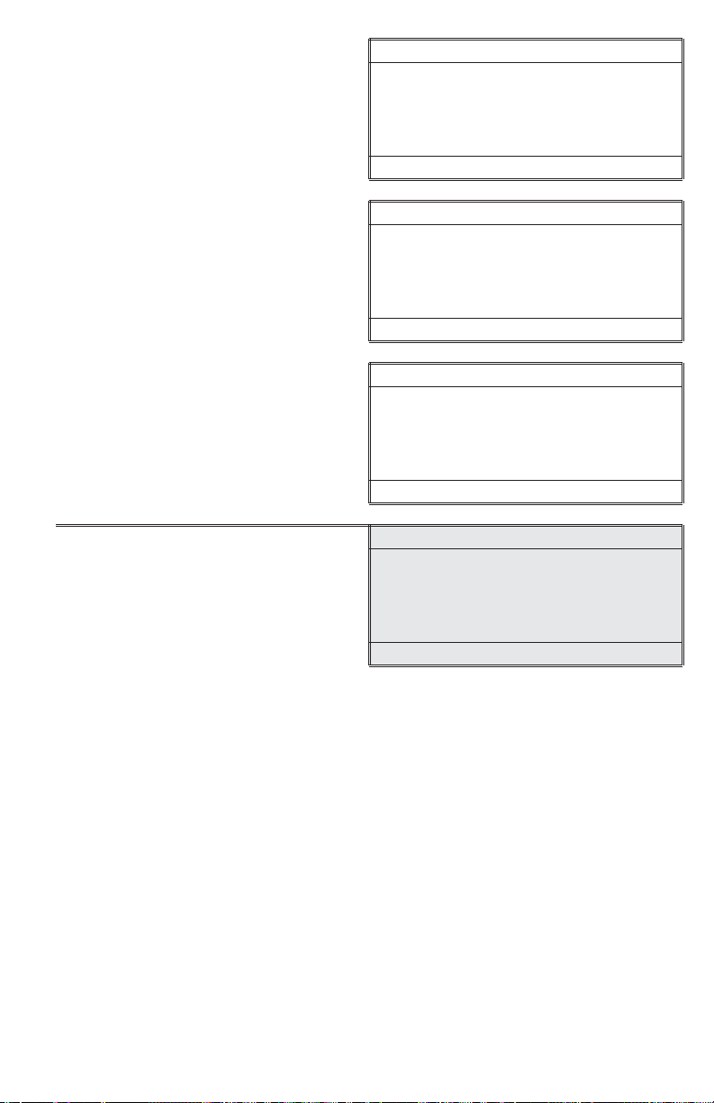
TUBE POSITIONING RING
N
The Tube Positioning Ring
To put a ring on a tube, remove the cap from the tube.
The tube positioning ring has two tapered notches and one
squared-off notch. Place the ring on the tube with the
squared-off notch closest to the top of the tube and tapered
notches closer to the bottom of the tube. Align the single,
squared-off notch with the vertical, white indexing line that is
printed on the tube. Place the tube flat on a hard surface and
firmly press the ring onto the tube with equal pressure distributed
along the top of the ring.
To remove a ring, invert the uncapped tube on a soft surface,
such as a paper towel. Press down on the ring with equal
pressure distributed around the ring.
SQUARED-OFF
NOTCH
INDEXING
E
LI
ANAL YSIS & CALIBRATION
TURBIDITY
The default units are NTU and the default calibration curve is formazin. When (F)is
displayed in the upper right corner of the display, this indicates that the meter is in the
formazin mode. For the most accurate results, a user calibration should be performed.
The Attenuation calibration option should be used when samples are over 500 NTU.
The Japan Standard calibration mode should be used only with Japan Standards
(0–100 NTU). To change the settings see the Set Up instructions (see page 10).
22 TUBE POSITIONING RING • ANAL YSIS & CALIBRATION • TURBIDITY
Page 23
Analysis
1. Press ON to turn the meter on.
2. Press *IOK to select Measure. Main Menu
* Measure
Data Logging
Options
16:02:19 01/04/05
3. Press *IOK to select Turbidity. Measure
* Turbidity
Color
Chlorine
16:02:19 01/04/05
4. Rinse a clean tube (0290) three
times with the blank.
For the most accurate results, use
thesametubefortheblankandthe
sample.
1.3
5. Fill the tube to the fill line with the
blank. Pour the blank down the
inside of the tube to avoid creating
bubbles.
ANALYSIS & CALIBRATION • TURBIDITY 23
Page 24

6. Dry the tube with a lint-free cloth. Put
on a dry positioning ring. Cap the
tube. Wipe the tube thoroughly
again with a lint-free cloth.
7. Open the meter lid. Insert the tube
into the chamber. Align the index
notch on the positioning ring with
the index arrow on the meter. Close
the lid.
8. Press *IOK to select Scan Blank.
Remove the tube.
NOTE: For the best accuracy,
especially at low level turbidity, see
Tip 17 on page 33.
9. Rinse a clean tube (0290), or the
same tube, three times with the
water to be tested. Avoid spilling
water on the outside of the tube.
IMPORT ANT: Whilethetubeis
inverted, wipe the lip of the tube to
remove droplets of liquid that may
be present. This will prevent liquid
from being trapped under the ring
when the tube is returned to an
upright position.
10. Fill the tube to the fill line with the
sample. Pour the sample down the
inside of the tube to avoid creating
bubbles.
Turbidity (F)
* Scan Blank
q
16:02:19 01/04/05
24 ANALYSIS & CALIBRATION • TURBIDITY
Page 25

11. Cap the tube. Wipe the tube
thoroughly again with a lint-free
cloth.
12. Open the meter lid. Insert the tube
into the chamber. Align the index
notch on the positioning ring with
the index arrow on the meter. Close
the lid.
13. Press *IOK to select Scan Sample. Turbidity (F)
* Scan Sample
16:02:19 01/04/05
14. Record the result. Turbidity (F)
q
0.54 NTU
* Scan Sample q
16:02:19 01/04/05
15. Press OFF to turn the meter off or
press to exit to a previous menu
or make another menu selection.
Note: The meter will remember the last scanned blank reading. It is not necessary to
scan a blank each time the test is performed. To use the previous blank reading,
instead of scanning a new one, scroll to Scan Sample and proceed. For the most
accurate results, the meter should be blanked before each test and the same tube with
tubepositioningringshouldbeusedfortheblankandthereactedsample.
ANALYSIS & CALIBRATION • TURBIDITY 25
Page 26

Dilution Procedures
If a sample is encountered that is more than 4000 NTU, a careful dilution with 0 NTU
or very low turbidity water will bring the sample into an acceptable range. However,
there is no guarantee that halving the concentration will exactly halve the NTU value.
Particulates often react in an unpredictable manner when diluted.
Turbidity-Free Water
The definition of low turbidity and turbidity-free water has changed as filter technology
has changed and nephelometric instruments have become more sensitive. At one time
turbidity-free water was defined as water that had passed through a 0.6 micron filter.
Now 0.1 micron filters are available and higher purity water is possible. Water that has
been passed through a 0.1 micron filter could be considered particle free and
therefore turbidity free, 0 NTU water. Turbidity is caused by scattered light. Therefore,
low turbidity water is water without any particles that scatter a measurable amount of
light. But water that passed through a 0.1 micron filter may still have detectable light
scatter with modern instruments. This light scattering can be the result of dissolved
molecules or sub-micron sized particles that can not be filtered out of the water.
Because there may still be a small amount of scattered light from dissolved molecules,
high purity water is often called low turbidity water and assigned a value of 0.01 or
0.02 NTU. However, because this water is used as a baseline to compare to sample
water, the difference between the sample and the low turbidity or turbidity-free water
will be the same whether it is called 0.00 NTU or 0.02 NTU. For design simplicity the
TC-3000 uses the term turbidity-free water and the value of 0.00 NTU.
Preparation of T urbidity -F ree Water
A 0 NTU Standard (Code 1480) is included with the meter. An accessory package
(Code 4185) is available for preparing turbidity-free water for blanking the meter and
dilution of high turbidity samples.
The preparation of turbidity-free water requires careful technique. Introduction of
foreign matter will affect the turbidity reading. A filtering device with a special
membrane filter is used to prepare turbidity-free water. The filter, filter holder and
syringe must be conditioned by forcing at least two syringes full of deionized water
through the filtering apparatus to remove foreign matter. The first and second rinses
should be discarded. Turbidity-free water as prepared below may be stored in the dark
at room temperature in a clean glass bottle with a screw cap and used as required.
The storage container should be rinsed thoroughly with filtered deionized water before
filling. The water should be periodically inspected for foreign matter in bright light.
PROCEDURE
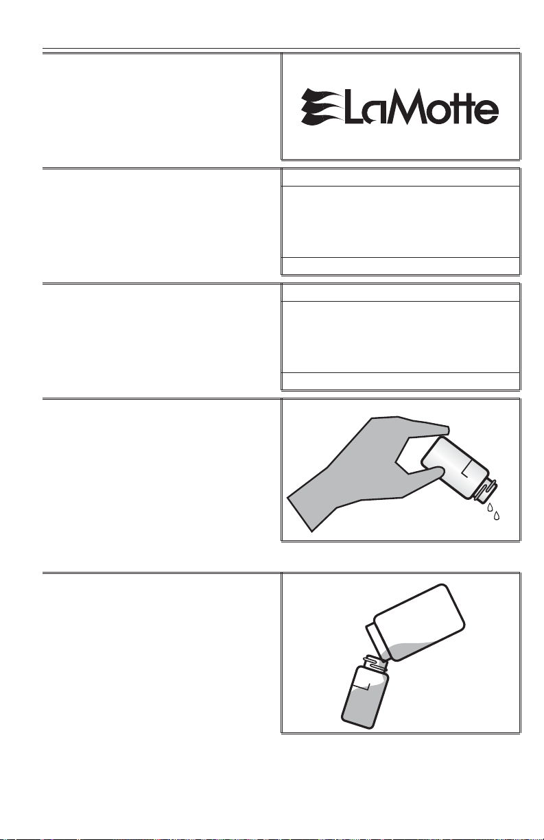
1. Remove the plunger from the syringe (0943). Attach the
filter to the bottom of the syringe.
26 ANALYSIS & CALIBRATION • TURBIDITY
Page 27

2. Pour approximately 50 mL of deionized water into the
barrel of the syringe. Insert the plunger. Exert pressure
on the plunger to slowly force the water through the
filter. Collect water in the clean storage container. Rinse
walls of the container then discard this rinse water.
3. Remove the filter from the syringe. Remove the plunger
from the barrel. (This step is required to prevent
rupturing the filter by the vacuum that would be created
when the plunger is removed.)
4. Replace the filter and repeat step 2 for a second rinse of
the syringe and storage container.
5. Remove the filter from the syringe. Remove the plunger
from the barrel. Replace the filter and fill the syringe with
approxiamtely 50 mL of deionized water. Filter the water
into the storage conatiner and save this turbidity-free
water.
6. Repeat Step 5 until the desired amount of turbidity-free
water has been collected.
ANALYSIS & CALIBRATION • TURBIDITY 27
Page 28

Turbidity Standards
Only use AMCO or formazin standards with the TC-3000. StablCalâ standards
below 50 NTU should not be used to calibrate the TC-3000. The diluent used in
StablCal
â
standards has a different refractive index than traditional formazin standards
and will affect the results. The concentration of the calibration standard should be
similar to the expected concentration of samples that will be tested. The following
standards are available from LaMotte Company:
1480 0 NTU Standard, 60 mL (EPA and ISO)
1484 1 NTU Standard, 60 mL (EPA)
1481 1 NTU Standard, 60 mL (ISO)
1485 10 NTU Standard, 60 mL (EPA)
1482 10 NTU Standard, 60 mL (ISO)
1486 100 NTU Standard, 60 mL (EPA)
1483 100 NTU Standard, 60 mL (ISO)
Calibration Procedure
1. Press ON to turn the meter on.
1.3
2. Press *IOK to select Measure. Main Menu
* Measure
Data Logging
Options
16:02:19 01/04/05
3. Press *IOK to select Turbidity. Measure
* Turbidity
Color
Chlorine
16:02:19 01/04/05
28 ANALYSIS & CALIBRATION • TURBIDITY
Page 29

4. Rinse a clean tube (0290) three
times with the blank.
Below 1 NTU – The meter should be
blanked with a 0 NTU Primary
Standard or prepared turbidity-free
(<0.1 NTU) water. For the most
accurate results, use the same tube
for the blank and the sample.
5. Fill the tube to the fill line with the
blank. Pour the blank down the
inside of the tube to avoid creating
bubbles. Cap the tube.
6. Dry the tube with a lint-free cloth. Put
on a dry positioning ring. Cap the
tube. Wipe the tube thoroughly
again with a lint-free cloth.
7. Open the meter lid. Insert the tube
into the chamber. Align the index
notch on the positioning ring with
the index arrow on the meter. Close
the lid.
8. Press *IOK to select Scan Blank.
Turbidity (F)
Remove the tube.
Note: For the best accuracy,
especially at low turbidity, see Tip 17
on page 33.
ANALYSIS & CALIBRATION • TURBIDITY 29
* Scan Blank
16:02:19 01/04/05
Page 30

9. Rinse a clean tube (0290), or the
same tube, three times with the
standard. Avoid spilling standard on
the outside of the tube.
IMPORT ANT: Whilethetubeis
inverted, wipe the lip of the tube to
remove droplets of liquid that may
be present. This will prevent liquid
from being trapped under the ring
when the tube is returned to an
upright position.
10. Fill the tube to the fill line with the
standard. Pour the standard down
the inside of the tube to avoid
creating bubbles. Cap the tube.
11. Wipe the tube thoroughly again with
a lint-free cloth.
12. Open the meter lid. Insert the tube
into the chamber. Align the index
notch on the positioning ring with
the index arrow on the meter. Close
the lid.
13. Press *IOK to select Scan Sample. Turbidity (F)
* Scan Sample
16:02:19 01/04/05
30 ANALYSIS & CALIBRATION • TURBIDITY
Page 31

14. Observe the result. Turbidity (F)
0.54 NTU
* Scan Sample q
16:02:19 01/04/05
15. Press and then press *IOK to
select Calibrate.
16. Use the or to change the
highlighted digits on the display to
match the concentration of the
turbidity standard. Press *IOK to
accept a digit and move to the
next digit.
Turbidity (F)
0.54 NTU
* Calibrate q
16:02:19 01/04/05
Calibrate
0
00.54
q , Q , p
16:02:19 01/04/05
Calibrate
0
01.54
q , Q , p
16:02:19 01/04/05
Calibrate
00.54
16:02:19 01/04/05
5
q , Q , p
Calibrate
00.54
16:02:19 01/04/05
Calibrate
00.50
16:02:19 01/04/05
ANALYSIS & CALIBRATION • TURBIDITY 31
4
q , Q , p
0
q , Q , p
Page 32

17. When the value on the display
matches the concentration of the
turbidity standard, press the *IOK
to select Set.
Calibrate
00.50
*Set q
16:02:19 01/04/05
Or press press *IOK to return
the meter to the default setting.
Calibrate
00.50
* Default p
16:02:19 01/04/05
18. Press *IOK to proceed to Turbidity
analysis. Press OFF to turn the meter
off or press to exit to a previous
menu or make another menu
selection.
Note: The meter will remember the last scanned blank reading. It is not necessary to
scan a blank each time the test is performed. To use the previous blank reading,
instead of scanning a new one, scroll to Scan Sample and proceed. For the most
accurate results, the meter should be blanked before each test and the same tube with
tubepositioningringshouldbeusedfortheblankandthereactedsample.
Testing Tips
1. Samples should be collected in a clean glass or polyethylene container.
2. Samples should be analyzed as soon as possible after collection.
3. Gently mix sample by inverting before taking a reading but avoid introducing air
bubbles.
4. For the most precise results, follow the recommended procedure for wiping a filled
tube before placing it in the meter chamber. Invert tube very slowly and gently
three times to mix the sample. Surround the tube with a clean, lint-free cloth. Press
the cloth around the tube. Rotate the tube in the cloth three times to assure that all
areas of the tube have been wiped.
5. Discard tubes that have significant scratches and imperfections in the light pass
zones. (Central zone between bottom and fill line).
6. When reading very low turbidity samples, do not use tubes or caps that have been
used previously with high turbidity samples.
7. Use the averaging option for low level measurements of turbidity.
8. The meter should be placed on a surface that is free from vibrations. Vibrations
can cause high readings.
9. Turbidity readings will be affected by electric fields around motors.
10. Carbon in the sample will absorb light and cause low readings.
32 ANALYSIS & CALIBRATION • TURBIDITY
Page 33

11. Excessive color in a sample will absorb light and cause high readings. The user
should verify if a certain level of color will cause a significant error at the level of
turbidity being tested.
12. Observe shelf life recommendations for turbidity standards.
13. Do not use silicone oil on tubes when testing turbidity with the TC-3000.
14. When testing at low concentrations use the same tube for the blank and the
sample.
15. Always use the positioning ring. Always insert tube into the meter chamber with the
same amount of pressure and to the same depth.
16. Occasionally clean the chamber with a damp lint-free wipe, followed by an
alcohol dampened wipe. A clean chamber and tubes are essential for reliable
results.
17. For the greatest accuracy during the calibration procedure, be sure that after the
meter is blanked and the blank is scanned as a sample, the reading is 0.00. If
not, reblank the meter and scan the blank again until it reads 0.00. When
scanning calibration standard as the sample, scan the calibration standard three
times removing the tube from the chamber after each scan. The readings should
be consistent. Use the last consistent reading to calibrate the meter. If the readings
are not consistent, avoid using an aberrant reading to calibrate the meter.
CHLORINE
The default units are ppm and the default calibration curve is for DPD Tablet reagents.
For the most accurate results, a user calibration should be performed. The letter (T) in
the upper right corner of the display indicates that the meter is in the tablet mode. To
use liquid DPD reagents, see the Set Up instructions.
Analysis
T ABLET DPD REAGENTS
Free Chlorine, Combined And Total Chlorine
1. Press ON to turn the meter on.
1.3
2. Press *IOK to select Measure. Main Menu
* Measure
Data Logging
Options
16:02:19 01/04/05
ANALYSIS & CALIBRATION • CHLORINE 33
Page 34

3. Scroll down and then press *IOK
to select Chlorine.
Measure
Turbidity
Color
* Chlorine
16:02:19 01/04/05
4. Press *IOK to select Test Free
Chlorine.
5. Rinse a clean tube (0290) with the
sample water.
6. Fill the tube to the 10 mL line with
thesamplewater.Drythetubewith
a lint-free cloth. Put on a dry
positioning ring. Cap the tube.
Chlorine (T)
* Test Free
Test Total
16:02:19 01/04/05
7. Open the meter lid. Insert the tube
into the chamber. Align the index
notch on the positioning ring with
the index arrow on the meter.
34 ANALYSIS & CALIBRATION • CHLORINE
Page 35

8. Close the lid and press *IOK to
select Scan Blank.
9. Removethetubefromthemeter.
Pour off all but a sufficient amount
of sample water to cover a tablet.
Add one *Chlorine DPD #1
Instrument Grade Tablet (6903).
Crush tablet with a tablet crusher
(0175) then add sample water until
the tube is filled to the 10 mL line.
Cap tube and shake until tablet
has dissolved. Solution will turn
pink if free chlorine is present. Wait
15 seconds but no longer than
30 seconds. Mix.
Free Chlorine (T)
* Scan Blank q
16:02:19 01/04/05
10. Open the meter lid. Insert sample
into chamber. Align the index notch
on the positioning ring with the index
arrow on the meter. Close lid, press
*IOK to select Scan Sample.
11. Record the result as Free Chlorine. Free Chlorine (T)
Free Chlorine (T)
* Scan Sample
16:02:19 01/04/05
1.00 ppm
* Scan Sample q
16:02:19 01/04/05
12. Removethetubefromthe
chamber. Add one *Chlorine
DPD #3 Instrument Grade Tablet
(6197). Crush tablet with Tablet
Crusher (0175). Cap tube and
shake until the tablet dissolves.
An increase in color represents
combined chlorine.
Note:
For wastewater samples, Standard Methods for the Examination of Water and
Wastewater recommends waiting 2 minutes for full color development when
testing total chlorine.
ANALYSIS & CALIBRATION • CHLORINE 35
Page 36

13. Open the meter lid. Insert sample
into chamber. Align the index notch
on the positioning ring with the index
arrow on the meter. Close lid, select
*IOK to select T otal Chlorine.
14. Record the result as Total Chlorine. Total Chlorine (T)
Free Chlorine (T)
1.00 ppm
* Total Chlorine q
16:02:19 01/04/05
1.25 ppm
* Scan Sample q
16:02:19 01/04/05
15. SubtracttheFreeChlorinereading
from the Total Chlorine reading to
obtain the concentration of
Combined Chlorine.
16. Press OFF to turn the meter off or
press to exit to a previous menu or
make another menu selection.
Total - Free = Combined
Chlorine Chlorine Chlorine
*Warning: Reagents marked with an * are considered to be potential health hazards.
To view or print a Material Safety Data Sheet (MSDS) for these reagents see MSDS CD
or go to www.lamotte.com. To obtain a printed copy, contact LaMotte by e-mail,
phone or fax.
Note: For the most accurate results, samples over 6 ppm chlorine should be diluted
with chlorine demand free water and re-tested.
Note: The meter will remember the last scanned blank reading. It is not necessary to
scan a blank each time the test is performed. To use the previous blank reading,
instead of scanning a new one, scroll to Scan Sample and proceed. For the most
accurate results, the meter should be blanked before each test and the same tube with
tubepositioningringshouldbeusedfortheblankandthereactedsample.
Tot a l Ch l o r in e
1. Press ON to turn the meter on.
1.3
36 ANALYSIS & CALIBRATION • CHLORINE
Page 37

2. Press *IOK to select Measure. Main Menu
* Measure
Data Logging
Options
16:02:19 01/04/05
3. Scroll down and then press *IOK
to select Chlorine.
4. Scroll down and press *IOK to
select Test Total Chlorine.
5. Rinse a clean tube (0290) with the
sample water. Fill the tube to the
10 mL line with the sample water.
Dry the tube with a lint-free cloth.
Put on a dry positioning ring. Cap
the tube.
6. Open the meter lid. Insert the tube
into the chamber. Align the index
notch on the positioning ring with
the index arrow on the meter. Close
the lid and press *IOK to select
Scan Blank.
Measure
Turbidity
Color
* Chlorine
16:02:19 01/04/05
Chlorine
Test Free
* Test Total
16:02:19 01/04/05
Total Chlorine (T)
*Scan Blank
16:02:19 01/04/05
7. Removethetubefromthemeter.
Pour off all but a sufficient amount of
sample water to cover a tablet. Add
one *Chlorine DPD #1 Instrument
Grade Tablet (6903). Crush tablet
with a tablet crusher (0175), then
add sample water until the tube is
filled to the 10 mL line. Cap tube
and shake until tablet has dissolved.
ANALYSIS & CALIBRATION • CHLORINE 37
Page 38

8. Add one *Chlorine DPD #3
Instrument Grade Tablet (6197).
Crush tablet with Tablet Crusher
(0175). Cap tube and shake until
the tablet dissolves.
Note: For wastewater samples, Standard Methods for the Examination of W ater and
Wastewater recommends waiting 2 minutes for full color development.
9. Open the meter lid. Insert sample
into chamber. Align the index notch
on the positioning ring with the index
arrow on the meter. Close lid, select
*IOK to select Scan Sample.
10. Record the result as Total Chlorine. Total Chlorine (T)
Total Chlorine (T)
* Scan Sample
16:02:19 01/04/05
1.00 ppm
* Scan Sample
16:02:19 01/04/05
11. Press OFF to turn the meter off or
press to exit to a previous menu
or make another menu selection.
*Warning: Reagents marked with an * are potential health hazards. To vi ew or pr in t a
Material Safety Data Sheet (MSDS) for these reagents see MSDS CD or go to
www.lamotte.com. To obtain a printed copy, contact LaMotte by e-mail phone or fax.
Note: For the most accurate results, samples over 6 ppm chlorine should be diluted
with chlorine demand free water and re-tested.
Note: The meter will remember the last scanned blank reading. It is not necessary to
scan a blank each time the test is performed. To use the previous blank reading,
instead of scanning a new one, scroll to Scan Sample and proceed. For the most
accurate results, the meter should be blanked before each test and the same tube with
tubepositioningringshouldbeusedfortheblankandthereactedsample.
38 ANALYSIS & CALIBRATION • CHLORINE
Page 39

LIQUID DPD REAGENTS
(Liquid calibration should be selected in the Options menu)
The letter (L) in the upper right corner of the display indicates that the meter is in liquid
mode.
Free Chlorine, Combined And Total Chlorine
1. Press ON to turn the meter on.
1.3
2. Press *IOK to select Measure. Main Menu
* Measure
Data Logging
Options
16:02:19 01/04/05
3. Scroll down and then press *IOK
to select Chlorine.
4. Press *IOK to select Test Free
Chlorine.
5. Rinse a clean tube (0290) with the
sample water. Fill the tube to the
10 mL line with the sample water.
Dry the tube with a lint-free cloth.
Put on a dry positioning ring. Cap
the tube.
Measure
Turbidity
Color
* Chlorine
16:02:19 01/04/05
Chlorine (L)
* Test Free
Test Total
16:02:19 01/04/05
ANALYSIS & CALIBRATION • CHLORINE 39
Page 40

6. Open the meter lid. Insert the tube
into the chamber. Align the index
notch on the positioning ring with
the index arrow on the meter. Close
the lid and press *IOK to select
Scan Blank.
7. Removethetubefromthemeter.
Add 5 drops of DPD 1A Free
Chlorine Reagent (P-6740). Cap
and mix.
8. Add 5 drops of *DPD 1B Free
Chlorine Reagent (P-6741). Cap
and mix. Solution will turn pink if
free chlorine is present. Read within
30 seconds.
Free Chlorine (L)
* Scan Blank
16:02:19 01/04/05
DPD
1A
DPD
1B
9. Open the meter lid. Insert tube into
chamber. Align the index notch on
the positioning ring with the index
arrow on the meter. Close lid, press
*IOK to select
Scan Sample.
10. Record the result as Free Chlorine. Total Chlorine (L)
Free Chlorine (L)
* Scan Sample
16:02:19 01/04/05
1.00 ppm
* Scan Sample
16:02:19 01/04/05
40 ANALYSIS & CALIBRATION • CHLORINE
Page 41

11. Removethetubefromthe
chamber. Add 5 drops of *DPD 3
Total Chlorine Reagent (P-6741).
Cap and mix. An increase in color
represents combined chlorine.
Note: For wastewater samples, Standard Methods for the Examination of Water and
Wastewater recommends waiting 2 minutes for full color development.
DPD
3
12. Open the meter lid. Insert the
sample into the chamber. Align the
index notch on the positioning ring
with the index arrow on the meter.
Close lid, select *IOK to select
T otal Chlorine.
13. Record the result as Total Chlorine. Total Chlorine (L)
Free Chlorine (L)
1.00 ppm
* Total Chlorine
16:02:19 01/04/05
~
1.25 ppm
* Scan Sample ~
16:02:19 01/04/05
14. SubtracttheFreeChlorinereading
from the Total Chlorine reading to
obtain the concentration of
Combined Chlorine.
15. Press OFF to turn the meter off or
press to exit to a previous menu
or make another menu selection.
To ta l
Chlorine
–
Free
Chlorine
Combined
=
Chlorine
ANALYSIS & CALIBRATION • CHLORINE 41
Page 42

* Warning: Reagents marked with an * are considered to be potential health hazards.
To view or print a Material Safety Data Sheet (MSDS) for these reagents see MSDS CD
or go to www.lamotte.com. To obtain a printed copy, contact LaMotte by e-mail,
phone or fax.
Note: For the most accurate results, samples over 6 ppm chlorine should be diluted
with chlorine demand free water and re-tested.
Note: The meter will remember the last scanned blank reading. It is not necessary to
scan a blank each time the test is performed. To use the previous blank reading,
instead of scanning a new one, scroll to Scan Sample and proceed. For the most
accurate results, the meter should be blanked before each test and the same tube with
tubepositioningringshouldbeusedfortheblankandthereactedsample.
Tot a l Ch l o r in e
1. Press ON to turn the meter on.
1.3
2. Press *IOK to select Measure. Main Menu
* Measure
Data Logging
Options
16:02:19 01/04/05
3. Scroll down and then press *IOK
to select Chlorine.
Measure
Turbidity
Color
* Chlorine
16:02:19 01/04/05
4. Press *IOK to select Test Total
Chlorine.
Chlorine (L)
Test Free
* Test Total
16:02:19 01/04/05
42 ANALYSIS & CALIBRATION • CHLORINE
Page 43

5. Rinse a clean tube (0290) with the
sample water. Fill the tube to the
10 mL line with the sample water.
Dry the tube with a lint-free cloth.
Put on a dry positioning ring. Cap
the tube.
6. Open the meter lid. Insert the tube
into the chamber. Align the index
notch on the positioning ring with
the index arrow on the meter. Close
the lid and press *IOK to select
Scan Blank.
7. Removethetubefromthemeter.
Add 5 drops of DPD 1A Free
Chlorine Reagent (P-6740). Cap
and mix.
8. Add 5 drops of *DPD 1B Free
Chlorine Reagent (P-6741). Cap
and mix.
Total Chlorine (L)
* Scan Blank
16:02:19 01/04/05
DPD
1A
DPD
1B
ANALYSIS & CALIBRATION • CHLORINE 43
Page 44

9. Add 5 drops of *DPD 3 Total
Chlorine Reagent (P-6741). Cap
and mix.
Note: For wastewater samples, Standard Methods for the Examination of Water and
Wastewater recommends waiting 2 minutes for full color development.
10. Open the meter lid. Insert the
sample into the chamber. Align the
index notch on the positioning ring
with the index arrow on the meter.
Close lid, select *IOK to select
Scan Sample.
11. Record the result as Total Chlorine. Total Chlorine (L)
Total Chlorine (L)
* Scan Sample
16:02:19 01/04/05
DPD
3
1.00 ppm
* Scan Sample
16:02:19 01/04/05
12. Press OFF to turn the meter off or
press to exit to a previous menu
or make another menu selection.
*Warning: Reagents marked with an * are considered to be potential health hazards.
To view or print a Material Safety Data Sheet (MSDS) for these reagents see MSDS CD
or go to www.lamotte.com. To obtain a printed copy, contact LaMotte by e-mail,
phone or fax.
Note: For the most accurate results, samples over 6 ppm chlorine should be diluted
with chlorine demand free water and re-tested.
Note: The meter will remember the last scanned blank reading. It is not necessary to
scan a blank each time the test is performed. To use the previous blank reading,
instead of scanning a new one, scroll to Scan Sample and proceed. For the most
accurate results, the meter should be blanked before each test and the same tube with
tubepositioningringshouldbeusedfortheblankandthereactedsample.
44 ANALYSIS & CALIBRATION • CHLORINE
Page 45

Dilution Procedures
Samples should be diluted with Chlorine Demand Free Water. To prepare Chlorine
Demand Free water follow the procedure in Standard Methods for the Analysis of
Water and Wastewater.
Standard Solutions
Standard solutions should be prepared from a sodium hypochlorite solution and
chlorine demand free water. The concentration of the standards should be verified by a
Ferrous Ammonium Sulfate titration. An approximately 250 ppm chlorine standard
(Code 6973-H, 60 mL) and a Chlorine titration kit (Code 3176-01) are available
from LaMotte Company.
Calibration Procedure
The meter should be calibrated with free chlorine standards. The calibration should be
done with a distilled or deionized water blank and one chlorine standard of known
concentration. The concentration of the calibration standard should be similar to the
expected concentration of samples that will be tested. The default reagent system is
DPD Tablets.
T ABLETS (Tablet calibration should be selected in the Options menu)
1. Press ON to turn the meter on.
1.3
2. Press *IOK to select Measure. Main Menu
* Measure
Data Logging
Options
16:02:19 01/04/05
3. Scroll down and then press *IOK
to select Chlorine.
Measure
Turbidity
Color
* Chlorine
16:02:19 01/04/05
ANALYSIS & CALIBRATION • CHLORINE 45
Page 46

4. Press *IOK to select Test Free
Chlorine.
5. Rinse a clean tube (0290) with the
chlorine standard. Fill the tube to
the 10 mL line with the sample
water. Dry the tube with a lint-free
cloth. Put on a dry positioning ring.
Cap the tube.
Chlorine (T)
* Test Free
Test Total
16:02:19 01/04/05
6. Open the meter lid. Insert the tube
into the chamber. Align the index
notch on the positioning ring with
the index arrow on the meter. Close
the lid and press *IOK to select
Scan Blank.
7. Removethetubefromthemeter.
Pour off all but a sufficient amount
of chlorine standard to cover a
tablet. Add one *Chlorine DPD #1
Instrument Grade Tablet (6903).
Crush tablet with a tablet crusher
(0175), then add chlorine standard
until the tube is filled to the 10 mL
line. Cap tube and shake until
tablet has dissolved. Solution will
turn pink if free chlorine is present.
Wait 15 seconds but no longer
than 30 seconds. Mix.
8. Open the meter lid. Insert tube into
chamber. Align the index notch on
the positioning ring with the index
arrow on the meter. Close lid, select
*IOK to select Scan Sample.
Free Chlorine (T)
*Scan Sample
16:02:19 01/04/05
Free Chlorine (T)
* Scan Sample
16:02:19 01/04/05
46 ANALYSIS & CALIBRATION • CHLORINE
Page 47

9. Observe the result. Free Chlorine (T)
1.00 ppm
* *Total Chlorine
16:02:19 01/04/05
10. Press to scroll to Calibrate. Press
*IOK to select Calibrate.
11. Use the or to change the
highlighted digits on the display to
match the concentration of the
chlorine standard. Press *IOK to
accept a digit and move to the
next digit.
Total Chlorine (T)
1.25 ppm
* Calibrate
16:02:19 01/04/05
Calibrate
0
01.25
q , Q , p
16:02:19 01/04/05
Calibrate
01.25
1
q , Q , p
16:02:19 01/04/05
Calibrate
01.25
16:02:19 01/04/05
2
q , Q , p
p
Calibrate
01.35
16:02:19 01/04/05
Calibrate
01.30
16:02:19 01/04/05
ANALYSIS & CALIBRATION • CHLORINE 47
3
q , Q , p
0
q , Q , p
Page 48

12. When the value on the display
matches the concentration of the
chlorine standard, press the *IOK
to select Set.
Calibrate
1.30
*Set
16:02:19 01/04/05
Or press the and press *IOK to
return the meter to the default
setting.
Calibrate
1.30
* Default p
16:02:19 01/04/05
13. Press *IOK to proceed to Chlorine
analysis. Press OFF to turn the meter
off or press to exit to a previous
menu or make another menu
selection.
*Warning: Reagents marked with an * are considered to be potential health hazards.
To view or print a Material Safety Data Sheet (MSDS) for these reagents see MSDS CD
or go to www.lamotte.com. To obtain a printed copy, contact LaMotte by e-mail,
phone or fax.
Note: The meter will remember the last scanned blank reading. It is not necessary to
scan a blank each time the test is performed. To use the previous blank reading,
instead of scanning a new one, scroll to Scan Sample and proceed. For the most
accurate results, the meter should be blanked before each test and the same tube with
tubepositioningringshouldbeusedfortheblankandthereactedsample.
LIQUID DPD REAGENTS
(Liquid calibration should be selected in the Options menu)
1. Press ON to turn the meter on.
1.3
2. Press *IOK to select Measure. Main Menu
* Measure
Data Logging
Options
16:02:19 01/04/05
48 ANALYSIS & CALIBRATION • CHLORINE
Page 49

3. Scroll down and then press *IOK
to select Chlorine.
Measure
Turbidity
Color
* Chlorine
16:02:19 01/04/05
4. Press *IOK to select Test Free
Chlorine.
5. Rinse a clean tube (0290) with the
chlorine standard. Fill the tube to
the 10 mL line with the sample
water. Dry the tube with a lint-free
cloth. Put on a dry positioning ring.
Cap the tube.
6. Open the meter lid. Insert the tube
into the chamber. Align the index
notch on the positioning ring with
the index arrow on the meter. Close
the lid and press *IOK to select
Scan Blank.
7. Removethetubefromthemeter.
Add 5 drops of DPD 1A Free
Chlorine Reagent (P-6740). Cap
and mix.
Chlorine (L)
* Test Free
Test Total
16:02:19 01/04/05
Free Chlorine (L)
*Scan Sample
16:02:19 01/04/05
DPD
1A
ANALYSIS & CALIBRATION • CHLORINE 49
Page 50

8. Add 5 drops of *DPD 1B Free
Chlorine Reagent (P-6741). Cap
and mix. Read within 30 seconds.
DPD
1B
9. Open the meter lid. Insert tube into
chamber. Align the index notch on
the positioning ring with the index
arrow on the meter. Close lid, press
*IOK to select Scan Sample.
10. Press to scroll to Calibrate.Press
*IOK to select Calibrate.
11. Use the or to change the
highlighted digits on the display to
match the concentration of the
chlorine standard. Press *IOK to
accept a digit and move to the
next digit.
Free Chlorine (L)
*Scan Sample
16:02:19 01/04/05
Free Chlorine (L)
1.25 ppm
* Total Chlorine
16:02:19 01/04/05
Calibrate
0
01.25
q , Q , p
16:02:19 01/04/05
Calibrate
1
01.25
q , Q , p
16:02:19 01/04/05
p
Calibrate
01.25
16:02:19 01/04/05
50 ANALYSIS & CALIBRATION • CHLORINE
2
q , Q , p
Page 51

Calibrate
12. When the value on the display
matches the concentration of the
chlorine standard, press *IOK to
select Set.
Or press the and press *IOK to
return the meter to the default
setting.
13. Press *IOK to proceed to Chlorine
analysis. Press OFF to turn the meter
off or press to exit to a previous
menu or make another menu
selection.
01.35
16:02:19 01/04/05
Calibrate
01.30
16:02:19 01/04/05
Calibrate
3
q , Q , p
0
q , Q , p
1.30
*Set
16:02:19 01/04/05
Calibrate
1.30
* Default p
16:02:19 01/04/05
*Warning: Reagents marked with an * are considered to be potential health hazards.
To view or print a Material Safety Data Sheet (MSDS) for these reagents see MSDS CD
or go to www.lamotte.com. To obtain a printed copy, contact LaMotte by e-mail,
phone or fax.
Note: The meter will remember the last scanned blank reading. It is not necessary to
scan a blank each time the test is performed. To use the previous blank reading,
instead of scanning a new one, scroll to Scan Sample and proceed. For the most
accurate results, the meter should be blanked before each test and the same tube with
tubepositioningringshouldbeusedfortheblankandthereactedsample.
ANALYSIS & CALIBRATION • CHLORINE 51
Page 52

Testing Tips
1. Wash tubes thoroughly afer testing to prevent staining of tubes and contamination
of future test reactions with DPD residue.
2. When using liquid DPD reagents, invert bottle in a completely vertical position to
dispense uniform drops. Do not tilt bottle at an angle.
3. Follow instructions. Obey time limits.
4. In samples with extremely high chlorine concentrations, above 10 ppm, the
reagent system will show an initial flash of dark pink color that will fade quickly.
Dilute the sample and test again.
5. When testing salt water, double the amount of reagent used. Use ten drops of
each DPD liquid reagent or two DPD tablets.
6. Oxidized manganese (permanganate) will interfere with this test. Iodine and
bromine will give a positive interference.
7. A permanganate check standard is not recommended for calibration when using
the liquid DPD reagent system.
8. The averaging option is not available for the chlorine test.
9. When testing at low concentrations use the same tube for the blank and the
sample.
10. Always use the tube positioning ring. Always insert tube into the meter chamber
with the same amount of pressure and to the same depth.
11. Occasionally clean the chamber with a damp lint-free wipe, followed by an
alcohol dampened wipe. A clean cahmber and tubes are essential for reliable
results.
COLOR
Test results are reported as cu (Color Units).
Analysis
1. Press ON to turn the meter on.
1.3
2. Press *IOK to select Measure. Main Menu
* Measure
Data Logging
Options
16:02:19 01/04/05
52 ANALYSIS & CALIBRA TION • CHLORINE • COLOR
Page 53

3. Scroll down and then press *IOK to
select Color .
4. Rinse a clean tube (0290) with
color-free (distilled or deionized)
water. Fill the tube to the 10 mL
line with color-free water. Dry the
tube with a lint-free cloth. Put on a
dry positioning ring. Cap the tube.
Measure
Turbidity
* Color
Chlorine
16:02:19 01/04/05
5. Open the meter lid. Insert the tube
into the chamber. Align the index
notch on the positioning ring with
the index arrow on the meter. Close
the lid and press *IOK to select
Scan Blank.
6. Removethetubefromthemeter.
Empty the tube. Rinse the tube with
the sample water. IMPORTANT:
While the tube is inverted, wipe the
lipofthetubetoremovedroplets
of liquid that may be present. This
will prevent liquid from being
trapped under the ring when the
tube is returned to an upright
position.
7. Fill the tube to the fill line with the
sample water. Pour the blank down
the inside of the tube to avoid
creating bubbles.
Color
* Scan Blank
16:02:19 01/04/05
ANALYSIS & CALIBRATION • COLOR 53
Page 54

8. Cap the tube. Wipe the tube
thoroughly again with a lint-free
cloth.
9. Open the meter lid. Insert the tube
with the sample water. Align the
index notch on the positioning ring
with the index arrow on the meter.
Close the lid. Scroll down and press
*IOK to select Scan Sample.
10. Record the result. Color
Color
* Scan Sample
16:02:19 01/04/05
28.0 cu
* Scan Sample
16:02:19 01/04/05
11. Press OFF to turn the meter off or
press to exit to a previous menu
or make another menu selection.
Note: The meter will remember the last scanned blank reading. It is not necessary
to scan a blank each time the test is performed. To use the previous blank
reading, instead of scanning a new one, scroll to Scan Sample and proceed. For
the most accurate results, the meter should be blanked before each test and the
same tube with tube positioning ring should be used for the blank and the reacted
sample.
Dilution Procedures
Samples and standards may be diluted with distilled or deionized water.
Standard Solutions
The meter has been calibrated with colored standards of known concentrations of
platinum cobalt. One unit of color is equivalent to the color that is produced by 1 mg
platinum/L in the form of the chloroplatinate ion. A 500 cu Color Standard (60 mL,
Code 6058-H) is available from LaMotte.
54 ANALYSIS & CALIBRA TION • COLOR
Page 55

Calibration Procedure
The meter should be calibrated with platinum cobalt color standards. For the most
accurate results, a user calibration should be performed with LaMotte Color
Standards. The calibration should be done with a distilled or deionized water blank
and one color standard of known concentration. The concentration of the calibration
standard should be similar to the expected concentration of samples that will be
tested.
1. Press ON to turn the meter on.
1.3
2. Press *IOK to select Measure. Main Menu
* Measure
Data Logging
Options
16:02:19 01/04/05
3. Scroll down and then press *IOK to
select Color .
4. Rinse a clean tube (0290) with
color-free (distilled or deionized)
water. Fill the tube to the 10 mL
line with color-free water. Dry the
tube with a lint-free cloth. Put on a
dry positioning ring. Cap the tube.
5. Open the meter lid. Insert the tube
into the chamber. Align the index
notch on the positioning ring with
the index arrow on the meter. Close
the lid and press *IOK to select
Scan Blank.
Measure
Turbidity
* Color
Chlorine
16:02:19 01/04/05
Color
* Scan Blank
16:02:19 01/04/05
ANALYSIS & CALIBRATION • COLOR 55
Page 56

6. Removethetubefromthemeter.
Empty the tube. Rinse the tube with
the color standard. IMPORTANT:
While the tube is inverted, wipe the
lipofthetubetoremovedroplets
of liquid that may be present. This
will prevent liquid from being
trapped under the ring when the
tube is returned to an upright
position.
7. Fill the tube to the fill line with the
color standard. Pour the blank down
the inside of the tube to avoid
creating bubbles.
8. Cap the tube. Wipe the tube
thoroughly again with a lint-free
cloth.
9. Open the meter lid. Insert the tube
with the color standard. Align the
index notch on the positioning ring
with the index arrow on the meter.
Close the lid. Press *IOK to select
Scan Sample.
10. View the result. Color
Color
* Scan Sample
16:02:19 01/04/05
28.0 cu
* Scan Sample
16:02:19 01/04/05
56 ANALYSIS & CALIBRA TION • COLOR
Page 57

11. Press and then press *IOK to
select Calibrate.
Color
28.0 cu
* Calibrate ~
16:02:19 01/04/05
12. Use or to change the
highlighted digits on the display to
match the concentration of the color
standard. Press *IOK to accept a
digit and move to the next digit.
Calibrate
0
028.0
q , Q , p
16:02:19 01/04/05
Calibrate
028.0
2
q , Q , p
16:02:19 01/04/05
Calibrate
3
038.0
q , Q , p
16:02:19 01/04/05
Calibrate
038.0
16:02:19 01/04/05
8
q , Q , p
Calibrate
030.0
16:02:19 01/04/05
Calibrate
030.0
16:02:19 01/04/05
ANALYSIS & CALIBRATION • COLOR 57
0
q , Q , p
0
q , Q , p
Page 58

13. When the value on the display
matches the concentration of the
color standard, press *IOK to select
Set.
Calibrate
030.0
*Set
16:02:19 01/04/05
Or press the and press *IOK
to return the meter to the default
setting.
Calibrate
030.0
* Default
16:02:19 01/04/05
14. Press *IOK to proceed to Turbidity
analysis. Press OFF to turn the meter
off or press to exit to a previous
menu or make another menu
selection.
Note: The meter will remember the last scanned blank reading. It is not necessary to
scan a blank each time the test is performed. To use the previous blank reading,
instead of scanning a new one, scroll to Scan Sample and proceed. For the most
accurate results, the meter should be blanked before each test and the same tube with
tubepositioningringshouldbeusedfortheblankandthereactedsample.
Testing Tips
1. Always use a clean test tube.
2. Use the averaging option for low level measurements of color.
3. Turbidity will interfere with the color test. Sample may be filtered before testing but
results will be as true color. (See What is Color?, page 22)
4. When testing at low concentrations use the same tube for the blank and the
sample.
5. Always use the positioning ring. Always insert tube into the meter chamber with the
same amount of pressure and to the same depth.
6. Occasionally clean the chamber with a damp lint-free wipe, followed by an
alcohol dampened wipe. A clean chamber and tubes are essential for reliable
results.
58 ANALYSIS & CALIBRA TION • COLOR
Page 59

TROUBLESHOOTING GUIDE
ERROR MESSAGES
Err1 Very Low battery. Replace battery or switch to AC power. Press back
arrow () to back out. Scan sample again. Replace battery as soon as
possible.
Err2 The meter can not be calibrated outside of the allowable range of the
displayed reading. Confirm that standard was made correctly. The
displayed reading can only be adjusted to ±50% of the factory
calibration.
Err3 Meter can not be calibrated with a zero sample. Calibrate the meter
with a sample other than zero.
Err4 Processing error due to motion of suspended particles or sub micron
air bubbles or opening/closing lid during readings. Scan sample again
until reading is obtained.
Err5 No blank reading. The meter has never been blanked for this test
factor. Blank meter.
Err6 Internal mathematical error. Re-blank the meter and rescan the
sample.
Err7 Configuration error. Call LaMotte Tech Service. Meter may have to be
returned for repairs.
low battery Low battery. Change battery.
TROUBLESHOOTING
PROBLEM REASON SOLUTION
Lost in meter
menus
Unusually large
negative or
positive readings
when performing
calibration.
Erroneous
readings
Reset to factory default
settings. See page 10.
Incorrect standards used to
calibrate meter.
Measurement was taken with
lid open.
Hold down *IOK and press
ON. Release both buttons. Press
*IOK to select the default settings.
Meter will turn off and the factory
settings will be restored.
Use fresh 0.0 standard in clean,
labeled vial. Reset meter to factory
default settings. See procedure
above. Recalibrate meter.
Close lid. Read again.
> on display Over range. The sample is outside of the
acceptable range. Dilute sample
and test again.
Meter freezes Lid was opened when
reading was being taken.
TROUBLESHOOTING 59
Close lid. Read again. Unplug
adapter. Plug adapter in to reset.
Page 60

STRAY LIGHT
p
The accuracy of readings on the TC-3000 should not be affected by stray light. Make
sure that the sample compartment lid is always fully closed when taking readings.
GENERAL OPERATING INFORMATION
OVERVIEW
The TC-3000 is a portable, microprocessor controlled, direct reading colorimeter and
nephelometer. Turbidity is measured directly by either EPA Method 180.1 or ISO
Method 7027. Color is measured directly in terms of platinum/cobalt color units.
Chlorine is determined by reaction with DPD reagents, followed by colorimetric
measurement of the reaction. It has a graphical liquid crystal display and 6 button
keypad. These allow the user to select options from the menu driven software, to
directly read test results, or to review stored results of previous tests in the data logger.
The menus can be displayed in six different languages.
The TC-3000 uses a state of the art, multi-detector micro optical configuration for
each test factor that assures long term stability of calibrations, high precision and
accuracy, and low detection limits. All readings are determined by sophisticated digital
signal processing algorithms, minimizing fluctuations in readings and enabling rapid,
repeatable measurements. The microprocessor and optics enable a dynamic range
and auto-ranging over several ranges for each test factor. Energy efficient LED light
sources are used for ISO turbidity, chlorine and color. EPA turbidity uses a tungsten
filament light source that meets or exceeds EPA specifications and is designed for a
uniform light spot image and stable output.
Tube positioning rings are supplied with the TC-3000. These rings snap onto the
shoulders of the tubes. The rings ensure that the tubes are positioned in the chamber
in the same orientation from one reading to the next. This minimizes variations in
readings due to differences in tube position. This results in greater repeatability and is
especially important for samples
with low turbidity.
A 9-volt alkaline battery powers
the TC-3000 and an optional
AC adapter is available. A fresh
battery should be installed at all
times even when using the AC
adapter.
An RS232 serial port on the
back of the meter allows an
interface of the meter with an
IBM compatible computer for
real-time data acquisition and
data storage using a PC. The
TC-3000 may be interfaced with
any Windows-based computer
by using the LaMotte SMARTLink
2 Program. The port also allows
an interface with an RS232
serial printer.
AC
Ada
Back
View
Lid
ter Socket
RS232
Serial Port
Side
View
60 TROUBLESHOOTING •GENERAL OPERATING INFORMATION
Page 61

Top
View
L
Mott
TC•3000
OK
Bottom
View
ONOFF
Serial
Number
Battery
Compartment
GENERAL OPERATING INFORMATION 61
Page 62

GENERAL OPERATING INFORMATION
The operation of the TC-3000 is controlled by the menu driven software and user
interface. A menu is a list of choices. This allows a selection of various tasks for the
TC-3000 to perform, such as, scan blank and scan sample. The keypad is used to
make menu selections that are viewed on the display.
THE KEYPAD
This button will scroll down through a list of menu selections.
*IOK This button is used to select menu choices adjacent to the * in a menu viewed
in the display
This button will scroll up through a list of menu selections.
OFF This button turns the TC-3000 off.
This button is an exit or escape button. When pressed, the display will exit the
current menu and go to the previous menu.
ON This button is used to turn on the TC-3000.
L
Mott
TC•3000
OK
ONOFF
62 GENERAL OPERATING INFORMATION
Page 63

THE DISPLAY & MENUS
The display allows menu selections to be viewed and selected. These selections instruct
the TC-3000 to perform specific tasks. The menus are viewed in the display using two
general formats that are followed from one menu to the next. Each menu is a list of
choices or selections.
The display has a header line at the top and a footer line at the bottom. The header
displays the title of the current menu. The footer line displays the time and the date.
The menu selection window is in the middle of the display between the header and the
footer.
The menu selection window displays information in two general formats. In the first
format only menu selections are displayed. Up to 4 lines of menu selections may be
displayed. If more selections are available they can be viewed by pressing the arrow
buttons ( or ) to scroll the other menu selections into the menu selection window.
Think of the menu selections as a vertical list in the display that moves up or down
each time an arrow button ( or ) is pressed. All menus in the TC-3000 are looping
menus. The top and bottom menu choices are connected in a loop. Scrolling down
past the bottom of the menu will lead to the top of the menu. Scrolling up past the top
of the menu will lead to the bottom of the menu.
Header Menu Title
* First Choice
Menu Selection Window Second Choice
Another
and another
Footer 16:02:19 01/04/05
and another
and so on
An asterisk, *, will start in the far left position of the top line in the menu choice
window. To move the * press the up or down arrow buttons ( or ) to scroll through
the menu selections. The * in the display corresponds with the *IOK button. Pushing
the *IOK button selects the menu choice which is adjacent to the * in the menu
selection window.
In the second format the menu choice window takes advantage of the graphical
capabilities of the display. Large format graphic information, such as test results or
error messages or the LaMotte logo is displayed. The top three lines of the display are
used to display information in a large, easy to read format. The menus work in the
same way as previously described but only one line of the menu is visible at the bottom
of the display. On the lower right side of the display small up and down arrows ( or
) indicate that other menu selections are available above or below the one visible
line of the menu.
DISPLAY & MENUS 63
Page 64

Header Menu Title
Message or Result
Window
Message
or Result
Menu Selection Window * First Choice
Footer 16:02:19 01/04/05
Second Choice
another
andsoon
As described previously, the button allows an exit or escape from the current
menu and a return to the previous menu. This allows a rapid exit from an inner
menu to the main menu by repeatedly pushing the button. Pushing OFF at any
time will turn the TC-3000 off.
The display may show the following messages:
Err1 to Err7 Error messages. See Troubleshooting Guide, page 59.
low battery Low battery.
> Over range indicator.
pq More choices are available and can be viewed by scrolling
up and/or down through the display.
Header Identifies the current menu and information on units and
reagent systems if applicable. In the data logging mode the
number of the data point is displayed and the total number of
data points in the memory will be shown.
Footer Shows current time and date.
~
Header Menu Title
Message or Result
Window
Message
or Result
Menu Selection Window * First Choice
Footer 16:02:19 01/04/05
Second Choice
another
andsoon
64 DISPLAY & MENUS
Page 65

NEGATIVE RESULTS
There are always small variations in readings with analytical instruments. Often these
variations can be observed by taking multiple readings of the same sample. These
variations will fall above and below an average reading. Repeated readings on a 0.00
sample might give readings above and below 0.00. Therefore, negative readings are
possible and expected on samples with concentrations at or near zero. This does not
mean there is a negative concentration in the sample. It means the sample reading
was less that the blank reading. Small negative readings can indicate that the sample
was at or near the detection limit. This is a normal variation that results in a negative
reading. A large negative reading, however, is not normal and indicates a problem.
Some instruments are designed to display negative readings as zero. In this type of
instrument, if the meter displayed zero when the result was actually a large negative
number there would be no indication that a problem existed. For this reason, the
TC-3000 displays negative numbers.
TUBES
The TC-3000 uses one type of tube (Code 0290) for the turbidity, color and chlorine
tests. There is no need for a special turbidity tube.
The handling of the tubes is of utmost importance. Tubes must be clean and free from
lint, fingerprints, dried spills and significant scratches, especially the central zone
between the bottom and the sample line.
Scratches, fingerprints and water droplets on the tube can cause stray light interference
leading to inaccurate results especially when measuring turbidity. Scratches and
abrasions will affect the accuracy of the readings for all test factors. Tubes that have
been scratched in the light zone through excessive use should be discarded and
replaced with new ones.
Tubes should always be washed on the inside and outside with mild detergent prior to
use to remove dirt or fingerprints. The tubes should be allowed to air-dry in an inverted
position to prevent dust from entering the tubes. To prevent introducing moisture into
the meter chamber, tube positioning rings should be removed before washing tubes. If
tubes are washed with tube positioning rings in place, the rings should be removed
and thoroughly dried before replacing them on the dry tubes. Dry tubes should be
stored with the caps on to prevent contamination.
After a tube has been filled and capped, it should be held by the cap and the outside
surface should be wiped with a clean, lint-free absorbent cloth until it is dry and
smudge-free. Handling the tube only by the cap will avoid problems from fingerprints.
Always set the clean tube aside on a clean surface that will not contaminate the tube. It
is imperative that the tubes and light chamber be clean and dry. The outside of the
tubes should be dried with a clean, lint-free cloth or disposable wipe before they are
placed in the meter chamber.
Tubes should be emptied and cleaned as soon as possible after reading a sample to
prevent deposition of stains or particulates on the inside of the tubes. Reacted chlorine
samples at high concentrations will stain the tubes. When highly accurate results are
required, reduce error by designating tubes to be used only for chlorine, very low
turbidity and very high turbidity testing.
Variability in the geometry of the glassware and technique are the predominate causes
of variability in results. Slight variations in wall thickness and the diameter of the tubes
NEGATIVE RESULTS • TUBES 65
Page 66

may lead to slight variations in the test results. To eliminate this error the tubes shoulbe
placed in the chamber with the same orientation each time. The orientation of the
tubes in the chamber is controlled by use of a tube positioning ring. For improved
accuracy and precision, especially at low concentrations, the tubes should always be
used with a positioning ring. (See page 22)
PC LINK
The TC-3000 may be interfaced with any Windows-based computer by using the
LaMotte SMARTLink 2 Program and Interface Cable (Code 1912-3 with 3.5 inch disk
or Code 1912-CD with compact disk). The program will store test information and
results in a database. The meter may also be interfaced with an RS232 serial printer,
using an interface cable (Code 1772) and setting the printer configuration to the
Output as described below.
OUTPUT
RS232 compatible, asynchronous serial, 9600 baud, no parity, 8 data bits, 1 stop bit.
COMPUTER CONNECTION
RS232 interface connection, 8 pin mini-DIN/9 pin F D-submin. (Order Interface
Cable Code 1772).
BATTER Y OPERATION
The TC-3000 may be operated on battery power or using an AC adapter. If using the
meter as a bench top unit, use the AC adapter if possible. If using the meter only on
battery power, always keep a spare battery on hand.
REPLACING THE BATTER Y
The TC-3000 uses a standard 9-volt alkaline battery that is available worldwide. The
battery compartment is located on the bottom of the case.
To replace the battery:
1. Open the battery compartment lid.
2. Remove the battery and disconnect the battery from the polarized plug.
3. Carefully connect the new battery to the polarized plug and insert it into the
compartment.
4. Close the battery compartment lid.
MAINTENANCE
CLEANING
Clean meter with a damp, lint-free cloth.
DO NOT ALLOW WATER TO ENTER THE METER CHAMBER OR ANY OTHER PARTS
OF THE METER.
Clean meter chamber and lenses over LEDs with a lint-free cloth slightly dampened
with alcohol.
66 PC LINK • BA TTER Y OPERA TION • MAINTENANCE
Page 67

METER DISPOSAL
Waste Electrical and Electronic Equipment (WEEE)
Natural resources were used in the production of this equipment. This equipment may
contain materials that are hazardous to health and the environment. To avoid harm to
the environment and natural resources, the use of appropriate take-back systems is
recommended. The crossed out wheeled bin symbol on the meter encourages you to
use these systems when disposing of this equipment.
Take-back systems will allow the materials to be reused or recycled in a way that will
not harm the environment. For more information on approved collection, reuse, and
recycling systems contact your local or regional waste administration or recycling
service.
REPAIRS
Should it be necessary to return the meter for repair or servicing, pack the meter
carefully in a suitable container with adequate packing material. A return authorization
number must be obtained from LaMotte Company by calling 800-344-3100 (US only)
or 410-778-3100, faxing 410-778-6394, or emailing tech@lamotte.com. Often a
problem can be resolved over the phone or by email. If a return of the meter is
necessary, attach a letter with the return authorization number, meter serial number, a
brief description of problem and contact information including phone and FAX
numbers to the shipping carton. This information will enable the service department to
make the required repairs more efficiently.
MAINTENANCE 67
Page 68

GENERAL INFORMATION
PACKAGING AND DELIVERY
Experienced packaging personnel at LaMotte Company assure adequate protection
against normal hazards encountered in transportation of shipments.
After the product leaves LaMotte Company, all responsibility for safe delivery is assured
by the transportation company. Damage claims must be filed immediately with the
transportation company to receive compensation for damaged goods.
GENERAL PRECAUTIONS
READ THE INSTRUCTION MANUAL BEFORE ATTEMPTING TO SET UP OR
OPERATE THE METER. Failure to do so could result in personal injury or damage to
the meter. The meter should not be used or stored in a wet or corrosive environment.
Care should be taken to prevent water from wet tubes from entering the meter
chamber.
NEVER PUT WET TUBES IN THE METER.
SAFETY PRECAUTIONS
Read the label on all reagent containers. Some labels include precautionary notices
and first aid information. Certain reagents are considered potential health hazards and
are designated with a * in the instruction manual. To view or print a Material Safety
Data Sheet (MSDS) for these reagents see MSDS CD or our web site,
www.lamotte.com. To obtain a printed copy, contact us by e-mail, phone or FAX.
Additional information for all LaMotte reagents is available in the United States,
Canada, Puerto Rico, and the US Virgin Islands from Chem-Tel by calling
1-800-255-3924. For other areas, call 813-248-0585 collect to contact Chem-Tel’s
International access number. Each reagent can be identified by the four-digit number
listed on the upper left corner of the reagent label, in the content list and in the test
procedures.
LIMITS OF LIABILITY
Under no circumstances shall LaMotte Company be liable for loss of life, property,
profits, or other damages incurred through the use or misuse of their products.
68 GENERAL INFORMATION
Page 69

SPECIFICATIONS- T C-3000e and TC-3000i
Instrument Type: Turbidity: Nephelometer
Color: Colorimeter
Chlorine: Colorimeter
Standard: Turbidity: EPA 180.1, TC-3000e
ISO7027, TC-3000i
Color: Adapted from Standard Methods 2120B
Chlorine: Standard Methods 4500-CL G
Units of Measure: Turbidity: NTU (Nephelometric Turbidity Units)
FNU (Formazin Nephelometric Units)
ASBC (American Society of Brewing Chemists)
EBC (European Brewery Convention)
FAU (Formazin Attenuation Unit)
Color: Platinum Cobalt Color Units (cu)
Chlorine: Parts Per Million (ppm), Milligrams Per Liter (mg/L)
Range: Turbidity: 0-4000 NTU, 0-4000 FNU, 40-4000 FAU,
0-35000 ASBC, 0-500 EBC
Color: 0.0–500.0 cu
Chlorine: 0.00–10.00 ppm free and total chlorine
Range Selection: Turbidity: Automatic, TC-3000e, Automatic, TC-3000i
Color: Automatic, TC-3000e, Automatic, TC-3000i
Chlorine: Automatic, TC-3000e, Automatic, TC-3000i
Resolution: (display) Turbidity: 0.01 NTU, 0–10.99 NTU Range
0.1 NTU, 11–109.99 NTU Range
1 NTU, 110–4000 NTU Range
Color: 0.1 cu, 0–99.9 cu Range
1 cu, 100–500 cu Range
Chlorine: 0.01 ppm, 0–5 ppm Range
0.1 ppm, 5–10 ppm Range
Accuracy: Turbidity: ±0.05 or ±2% of reading, whichever is greater,
below 100 NTU
±3% of reading, above 100 NTU
Color: ±0.5 cu or ±2%, whichever is greater
Chlorine: ±0.02% ppm or 2%, whichever is greater,
0-5 ppm Range,
±10%, 5–10 ppm Range
Detection Limit: Turbidity: 0.05 NTU
Color: 0.2 cu
Chlorine: 0.02 ppm
Light Source: Turbidity: Tungsten lamp 2300°C±50°C, TC-3000e;
IR LED 860 nm ±10 nm, spectral bandwidth
50 nm, TC-3000i
Color: 375 ±5 nm UV LED
SPECIFICATIONS 69
Page 70

Chlorine: 525 ±2 nm LED
Detector: Turbidity: Photodiode, centered at 90°, maximum peak
550 nm, TC-3000e;
Photodiode, centered at 90°, TC-3000i
Color: Photodiode
Chlorine: Photodiode
Light Source
Automatic
Stabilization:
Response Time: <5 seconds
Signal Averaging: Turbidity and color
Sample Chamber: Accepts 25 mm flat-bottomed test tubes
Sample: 10 mL in capped tube
Display: Graphic Liquid Crystal Display
Software: Data Logging: 4004 points
Auto Shut-off: 5, 10, 30 min, disabled
Calibration: Field adjustable, 2-points
Languages: English, French, Spanish, Japanese (Kana), Portuguese, Italian
Temperature: Operation: 0–50 °C; Storage: -40–60 °C
Operation Humidity
0–90 % RH, non-condensing
Range:
Auto Shutdown: 0, 5, 10 or 30 minutes
Power Source*: Battery Operation: 9 volt alkaline
Line Operation: Input: 100-240VAC/50-60Hz with imbedded
IEC socket (2 pin)
Output: 9VDC REG 1.2A with 2.1 x 5.5 mm output plug
center positive
Battery Life: >250 tests, TC-3000e
>2500 tests, TC-3000i
(with signal averaging disabled)
Dimensions
16.2 x 8.5 x 6.7 cm; 6.4 x 3.4 x 2.6 inches
(LxWxH):
Weight: 339 g, 12 oz (meter only)
Serial Interface: RS232, 8 pin mDIN, 9600b, 8, 1, n
*CE Mark: The device complies to the product specifications for the Low Voltage
Directive when furnished with the 100-240V AC Adapter (Code 1754).
70 SPECIFICATIONS
Page 71

ST ATISTICAL AND TECHNICAL DEFINITIONS RELATED TO PRODUCT
SPECIFICATIONS
Method Detection Limit (MDL): “The method detection limit (MDL) is defined as the
minimum concentration of a substance that can be measured and reported with 99%
confidence that the analyte concentration is greater than zero and is determined from
analysis of a sample in a given matrix containing the analyte.”
William Horwitz once stated, ‘In almost all cases when dealing with a limit of detection
or limit of determination, the primary purpose of determining that limit is to stay away
from it.’”
2
Accuracy: Accuracy is the nearness of a measurement to the accepted or true value.
The accuracy can be expressed as a range, about the true value, in which a
measurement occurs (i.e. ±0.5 ppm). It can also be expressed as the % recovery of a
known amount of analyte in a determination of the analyte (i.e. 103.5 %).
Resolution: Resolution is the smallest discernible difference between any two
measurements that can be made.
4
For meters this is usually how many decimal places
are displayed. (i.e. 0.01). Note that the resolution many change with concentration or
range. In some cases the resolution may be less than the smallest interval, if it is
possible to make a reading that falls between calibration marks. A word of caution,
that resolution has very little relationship to accuracy or precision. The resolution will
always be less than the accuracy or precision but it is not a statistical measure of how
well a method of analysis works. The resolution can be very, very good and the
accuracy and precision can be very bad! This is not
a useful measure of the
performance of a test method.
Repeatability: Repeatability is the within-run precision.
from set up to clean up. Generally, one run occurs on one day. However, for meter
calibrations, a single calibration is considered a single run or data set, even though it
may take 2 or 3 days.
Reproducibility: Reproducibility is the between-run precision.
Detection Limit (DL): The detection limit (DL) for the TC-3000 is defined as the
minimum value or concentration that can be determined by the meter, which is greater
than zero, independent of matrix, glassware, and other sample handling sources of
error. It is the detection limit for the optical system of the meter.
1
Note that, “As Dr.
5
A run is a single data set,
6
3
1
CFR 40, part 136, appendix B
2
Statistics in Analytical Chemistry: Part 7 – A Review, D. Coleman and L Vanatta,
American Laboratory, Sept 2003, P. 31.
3
Skoog,D.A.,West,D.M.,Fundamental of Analytical Chemistry,2nded., Holt Rinehart
and Winston, Inc, 1969, p. 26.
4
Statistics in Analytical Chemistry: Part 7 – A Review, D. Coleman and L Vanatta,
American Laboratory, Sept 2003, P. 34.
5
Jeffery G. H., Basset J., Mendham J., Denney R. C., Vo gel’s Textbook of Quantitative
Chemical Analysis,5
6
Jeffery G. H., Basset J., Mendham J., Denney R. C., Vo gel’s Textbook of Quantitative
Chemical Analysis,5
ST ATISTICAL & TECHNICAL DEFINITIONS 71
th
ed., Longman Scientific & Technical, 1989, p. 130.
th
ed., Longman Scientific & Technical, 1989, p. 130
Page 72

CONTENTS AND ACCESSORIES
TC-3000e Trimeter Kit
EPA Version
Code 1964-EPA
CONTENTS Code Code
0 NTU Standard, 60 mL 1480 1480
1 NTU Standard, 60 mL 1484 1481
10 NTU Standard, 60 mL 1485 1482
*Chlorine DPD #1;
*6903A-J *6903A-J
Instrument Grade Tablets, 100
*Chlorine DPD #3;
*6197A-J *6197A-J
Instrument Grade Tablets, 100
Tablet Crusher 0175 0175
Water Sample Bottle, 60 mL 0688 0688
Tubes, 4 (Two with tube positioning
——
rings)
Battery, 9V — —
* Warning: Reagents marked with an * are considered a potential health hazard. To view or print a Material
Safety Data Sheet (MSDS) for these reagents see MSDS CD or go to www.lamotte.com. To obtain a printed
copy, contact LaMotte by e-mail, phone or fax.
ACCESSORIES
1486 100 NTU Standard, 60 mL (EPA)
1483 100 NTU Standard, 60 mL (ISO)
6197-L Chlorine DPD #1 Instrument Grade Tablets, 500 Tablets
6197-M Chlorine DPD #1 Instrument Grade Tablets, 1000 Tablets
6903-L Chlorine DPD #3 Instrument Grade Tablets, 500 Tablets
6903-M Chlorine DPD #3 Instrument Grade Tablets, 1000 Tablets
P-6740-G DPD #1A Free Chlorine Reagent, 30 mL
P-6740-H DPD #1A Free Chlorine Reagent, 60 mL
P-6741-G DPD #1B Free Chlorine Reagent, 30 mL
P-6741-H DPD #1B Free Chlorine Reagent, 60 mL
P-6743-G DPD #3 Total Chlorine Reagent, 30 mL
P-6743-H DPD #3 Total Chlorine Reagent, 60 mL
0475 Tubes, Code 0290, Set of 6
0641 Tube Positioning Ring, Pack of 2
6973-H Chlorine Standard, 250 ppm, 60 mL
3176-01 Chlorine Titration Kit, 0–10 ppm
4140 Chlorine Secondary Standards, Set of 4
6058-H Color Standard, 500 Color Units, 60 mL
4185 Turbidity-Free Water Kit
2-2097 Filters, 0.1 micron, Pack of 50
1772 Interface Cable, RS232
1754 AC Adapter, 9V (variable 100-240V)
1912-3 or 1912-CD SMARTLink 2 Software and Interface Cable
72 CONTENTS & ACCESSORIES
TC-3000i Trimeter Kit
ISO Version
Code 1964-ISO
Page 73

EPA COMPLIANCE
The TC-3000e meter meets or exceeds EPA design
specifications for NPDWR and NPDES turbidity
monitoring programs as specified by the USEPA
method 180.1.
ISO COMPLIANCE
This TC-3000i meter meets or exceeds ISO design
criteria for quantitative methods of turbidity using
optical turbidimeters as specified by ISO 7027.
CE COMPLIANCE
The TC-3000e and TC-3000i meters have been
independently tested and have earned the European
CE Mark of compliance for electromagnetic
compatibility and safety.
To view certificates of compliance, see our website
www.lamotte.com
NOTE: The device complies to the product specifications for the Low Voltage Directive
when furnished with the AC Adapter (Code 1754).
WARRANTY
This Instrument is guaranteed to be free from defects
in material and workmanship for a period of two (2)
years from the original purchase date. In the event
that a defect is found during the warranty time frame,
LaMotte Company agrees that it will be repaired or replaced without charge except for
the transportation costs. This guarantee does not cover batteries.
This product can not be returned without a return authorization number from LaMotte
Company. For warranty support or a Return Authorization Number, contact LaMotte
Company at 1-800-344-3100 or tech@lamotte.com.
EP A
COMPLIANT
ISO
COMPLIANCE
CE
2
MARK
YEAR
warranty
Limitations
This guarantee is void under the following circumstances:
• Damage due to operator negligence, misuse, accident or improper application.
•Damage or alterations from attempted repairs by an unauthorized (non-LaMotte)
service.
•Damage due to improper power source, AC adapter or battery.
•Damage caused by acts of God or natural disaster.
•Damage occurred while in transit with a shipping carrier.
LaMotte Company will service and repair out-of-warranty products at a nominal
charge
COMPLIANCE • WARRANTY 73
Page 74

74
Page 75

75
Page 76

LaMotte Company • PO Box 329 • 802 Washington Avenue
Chestertown • Maryland • 21620 • USA
USA 800-344-3100 • 410-778-3100 • fax 410-778-6394 • www.lamotte.com
Code 1964-MN
 Loading...