

Page 1
Vega 900 Handbook
�
Part Number 17155
NOMINAL INPUT VOLTAGE RANGE 165 - 240VAC
MAX. INPUT VOLTAGE RANGE 150 - 264VAC
INPUT FREQUENCY 47- 63Hz
MAXIMUM INPUT CURRENT 9 A AC
INRUSH CURRENT <40 AMPS
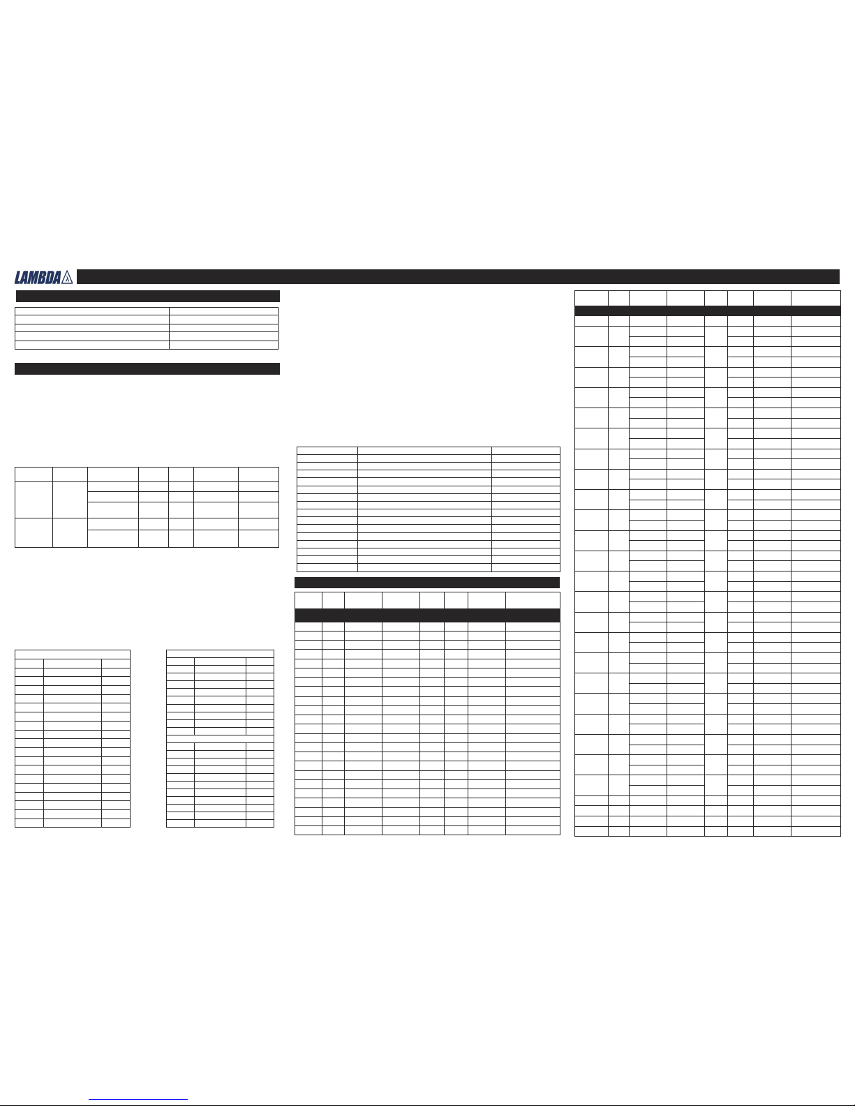
Adjustment and Derating.
The Vega 900 series is designed to provide a max output power of 900W at nominal output voltages. The following procedure must be used to ensure the PSU is operated within its ratings
a Calculate user power for each module (volts x amps).
b Add all the individual module powers together. The total power must not exceed the value
given.
c Calculate secondary transformer turns x amps for each module. See the outputs table
for transformer secondary turns.
d Add all the module turns x amps together and this must not exceed the ampere turns.
e If necessary reduce the loading until the conditions are met, ie. power and ampere-turns
maxima.
Input Parameters
Output Parameters
Test requirements include: PSU to be fitted in its end-use equipment and operated under the
most adverse conditions permitted in the end-use equipment handbook/specification and which
will result in the highest temperatures in the PSU. To determine the most adverse conditions
consideration should be given to the end use equipment maximum operating ambient, the PSU
loading and input voltage, ventilation, end use equipment orientation, the position of doors & covers, etc. Temperatures should be monitored using type K fine wire thermocouples (secured with
cyanoacrylate adhesive, or similar) placed on the hottest part of the component (out of any direct
airflow) and the equipment should be run until all temperatures have stabilised.
Customer Air Cooling (option C):
The following method must be used for determining the safe operation of PSUs when C option
(Customer Air) is fitted, ie fan not fitted to PSU.
For PSUs cooled by customer supplied airflow the components listed in the following table must
not exceed the temperatures given. Additionally ratings specified for units with an internal fan
must still be complied with, eg mains input voltage range, maximum output power, ampere turns,
module voltage / current ratings and maximum ambient temperature. To determine the component
temperatures the heating tests must be conducted in accordance with the requirements of
IEC/EN/CSA60950-1:2001 Clause 4.5. Consideration should also be give to the requirements of
other safety standards.
Note 1:The PSU main transformer has three regions for module secondaries seperated by two
primary windings. Starting nearest slot 1, region A, primary winding, region B, primary winding,
region C. The total ampere turns (AT) in any two adjacent regions is limited to that in the table
above column, “ Max AT in adjacent regions (note 1)”.See mains transformer regions table
below for modules allowed in each region. The table uses module widths with a twin output
module being single width.
n/a=not applicable
Main transformer regions table:
* Ruggedised fan (Papst 622HH, not for use in PSU’s fitted with IEC inlet).
Modules Note Output Range Current Slots Turns
Max. Current
Limit
Settings for hazard-
ous energy
Standard Modules
L1 4.2-5.5V 35A 1 1 43.8A >5.4V
H1L/1L
1.8-3.8V 12A
1
1 15A -
1.8-3.8V 8A 1 12A -
H1L/1H
1.8V-3.8V 12A
1
1 15A -
3.9-5.5V 8A 1 12A -
H1H/1L
3.9-5.5V 12A
1
1 15A -
1.8-3.8V 8A 1 12A -
H1H/1H
3.9-5.5V 12A
1
1 15A -
3.9-5.5V 8A 1 12A -
H1L/2
1.8-3.8V 12A
1
1 15A -
5.6-9V 6A 2 9A -
H1H/2
3.9-5.5V 12A
1
1 15A
5.6-9V 6A 2 9A -
H1L/3
1.8-3.8V 12A
1
1 15A -
9.1-16.2V 6A 3 9A -
H1H/3
3.9-5.5V 12A
1
1 15A -
9.1-16.2V 6A 3 7.5A -
H1L/4
1.8-3.8V 12A
1
1 15A -
16.3-25V 4.5A 4 6A -
H1H/4
3.9-5.5V 12A
1
1 15A -
16.3-25V 4.5A 4 6A -
H2/1L
5.6-9V 10A
1
2 15A -
1.8-3.8V 8A 1 12A -
H2/1H
5.6-9V 10A
1
2 15A -
3.9-5.5V 8A 1 12A -
H2/2
5.6-9V 10A
1
2 15A -
5.6-9V 6A 2 9A
H2/3
5.6-9V 10A
1
2 15A -
9.1-16.2 6A 3 7.5A -
H2/4
5.6-9V 10A
1
2 15A -
16.3-25V 4.5A 4 6A -
H3/1L
9.1-16.2V 10A
1
3 15A >16V
1.8-3.8V 8A 1 12A -
H3/1H
9.1-16.2V 10A
1
3 15A >16V
3.9-5.5V 8A 1 12A -
H3/2
9.1-16.2V 10A
1
3 15A >16V
5.6-9V 6A 2 9A -
H3-3
9.1-16.2V 10A
1
3 15A >16V
9.1-16.2V 6A 3 7.5A -
H3/4
9.1-16.2V 10A
1
3 15A >16V
16.3-25V 4.5A 4 6A -
H5/1L
16.2-28V 5A
1
5 7.5A >32V
1.8-3.8V 8A 1 12A -
H5/1H
16.2-28V 5A
1
5 7.5A >32V
3.9-5.5V 8A 1 12A -
H5/2
16.2-28V 5A
1
5 7.5A >32V
5.6-9V 6A 2 9A -
X1 6,7 0-10V 90A 1 - -
X2 6,7 0-20V 64.5A 1 - - -
X4 6,7 0-40V 32.4A 1 - ---
X8 6,7 0-80V 16.2A 1 - - -
Modules Note Output Range Current Slots Turns
Max. Current
Limit
Settings for hazard-
ous energy
Standard Modules
B1L 1.8-3.8V 20A 1 1 25A B1H 3.9-5.5V 20A 1 1 25A
B2 5.0-9V 25A 1 2 31.3A >7.6V
B3 9.1-16.2V 12A 1 3 15A >16V
B5 21.6-31V 6A 1 5 7.5A >32V
C1 1.8-4.1V 35A 1 1 43.8A >5.4V
C1Y 1 1.8-4.1V 40A 1 1 50A -
C3 9.1-16.2V 18A 1 3 22.5A >10.6V
C4 16.3-21.5V 14A 1 4 17.5A >13.7V
C5 21.6-31V 10A 1 5 12.5A >19.2V
D1L 2 1.8-3.8V 50A 1.5 1 62.5A >3.8V
D1H 2 3.9-5.5V 50A 1.5 1 62.5A >3.8V
D2 2 3.8-8V 45A 1.5 2 56.25A >4.2V
D3 2 8-16.5V 24A 1.5 3 30A >8V
D4 2 14-21.5V 18A 1.5 4 22.5A >10.6V
D5 2 21-28V 15A 1.5 5 18.75A >12.8V
E1 1.8-3.8V 60A 2 1 75A >3.2V
E2 3 3.8-8V 60A 2 2 75A >3.2V
E3L 8-13.9V 40A 2 3 50A >4.8V
E3H 14-15V 36A 2 3 45A >5.3V
E4 14-19.9V 30A 2 4 37.5A >6.4V
E5L 20-24V 27A 5 33.8A >7.1V
E5H 24-28V 25A 2 5 31.3A >7.6V
Slot 1 Slot 5.5
Region A Region B Region C
Single Dual Dual
Blank Dual Dual
Single Dual, Single Single
Single Dual Single
Single Dual -
- Dual -
Single Single, Single, Single Single
Single Single,Single Single
Single Single -
- Single -
1.5 Dual 1.5
Single Dual 1.5
- Dual 1.5
Single 1.5,Single Single
Single 1.5 -
Single 1.5 Single
1.5 1.5,Single Single
1.5 1.5 1.5
Slot 1 Slot 5.5
Region A Region B Region C
Single 1.5 1.5
- 1.5 1.5
- 1.5 -
- Single,Single Dual
- 1,5, Single Single
- Dual, Single Single
1.5 1.5 Single Single, Single Dual
1.5 1.5 Dual
Combined Modules
Single Dual Dual
- Dual Dual
1.5 Dual 1.5
Single Dual 1.5
- Dual 1.5
Single 1.5,1.5 Single
Single 1.5,1.5 -
- 1.5,1.5 -
1.5 1.5, Dual -
1.5 1.5, Single Single
1.5 1.5 1.5
Cooling
Option
Max
Ambient
Dual Width
Modules Fitted
Max
Power
Max AT
(total)
Max AT adjacent
regions (note 1)
Max Current
Rating
F,D
(Standard or
Ruggedised
Fan Foward
Airflow
50
No 900 220 180 100%
Yes 900 220 180 100%
No 650 220 n/a 100%
Q
(Quiet Fan
Foward
Aairflow
50
No 750 180 n/a 100%
Yes 750 180 140 100%
Modules
CIRCUIT REF. DESCRIPTION MAX. TEMP (°C)
- Power transformer primary, secondary and core 130
T1, TX101, TX201 Module current transformer windings 127
XQ1 E & F Primary option transformers 90
XTR1 EV & FV Primary option transformers 90
TX1 xEW & xFW Primary option transformers 130
L1, L2, XT601 Choke winding 110
T2 Choke winding 117
L4 Choke winding 120
Various All other choke & transformer windings 110
RLY1 Relay 100
C15 X capacitor 100
Various All other X capacitors 105
C2, C3, C4 Electrolytic Capacitor 67
Various All other 10mm dia Electrolytic Capacitor 80
Various All other 12.5mm dia Electrolytic Capacitor 85
Page 2
Vega 900 Handbook
�
Part Number 17155
Modules Note Output Range Current Slots Turns
Max. Current
Limit
Settings for hazard-
ous energy
Standard Modules
H5/3
16.2-28V 5A
1
5 7.5A >32V
9.1-15.5 6A 3 7.5A -
H5/4
16.2-28V 5A
1
5 7.5A >32V
16.3-24V 4.5A 4 6A -
Seriesed Modules
BB4 32.6-40V 10A 2 8 12.5A >19.2V
CC3 18.2-30V 18A 2 6 22.5A >10.6
CC5 48.1-60V 10A 2 10 12.5A
>19.2V
DD4 28-36V 18A 3 8 22.5A >10.6V
DD5 42-56V 15A 3 10 18.75A >12.8V
EE2 7.6-15V 55A 4 4 75A >3.2V
EE4 28-38V 30A 4 8 37.5 >6.4
EE5L 40-48V 18A 4 10 33.8 >7.1
EE5H 48-56V 18A 4 10 31.3 >7.6
HH5/3 25.3-38V 5A 1 8 7.5A >32V
HH5/4 32.5-46V 4.5A 1 9 6A >40V
C5B4 43-48V 10A 2 9 12.5A >19.2V
Paralleled Modules
Z2(D1L+D1L) 1.8-3.4V 95A 3 1+1 125A >1.9V
Z3(E1+E1) 1.8-3.4V 114A 4 1+1 150A >1.6V
Z4(D1H+D1H) 3.9-5.1V 95A 3 1+1 125A >1.9V
Z6(E2+D1H) 3.9-5.1V 104.5A 3.5 2+1 137.5A >1.7V
Z7(D3+D3) 8-15V 45.6A 3 3+3 60A >4V
Z18(L1+L1) 4.2-5.1V 66.5A 2 1+1 87.5A >2.7V
Z19 (E5H+D5) 24-28V 36 3.5 5+5 40.05A >5.9
Wide Range Modules
W5 5 0.25-32V 8.5A 1 5 9.5A 18>25.2V
1 C1Y module is only permitted in slot.
2 For PSUs with three D modules fitted or two D modules and an E module in slots
4/5 then D1L & D1H in slots 2/3 is limited to 42A and in slots 4/5 is limited to 47A.
D2 in slots 2/3 is limited to 40A.
3 E2 module fitted in slots 4/5 is limited to 55A.
4 SELV and Outputs connected in Series
Outputs are SELV except as described below
- Non-earthed outputs that have secondaries with 2 or more turns are non-SELV as
a single fault in the secondary may make them exceed the SELV limit between
output and earth.
- Non-earthed ouputs that are connected in series are non-SELV unless all the
seriesed outputs use 1 turn secondaries and there are no more than 3 outputs
connected in series.
- Outputs connected in series are non-SELV if the total output voltage + 20% of the
max, rated output voltage of the output with the highest rated voltage exceeds
60dc (the 20% addition allows for a single fault in any one individual channel)
- The total voltage of a seriesed output must not exceed 160V
- If any ouput or seriesed output is non-SELV then all the outputs in the PSU must
be considered non-SELV
Note
- Non-SELV outputs must be gaurded or a deflector fitted during installation to
avoid a service
engineer making inadvertent contact with the output terminals, or dropping a tool
onto them.
- All outputs operational spacings to earth, and due consideration must be given to
this in the end product design.
5 W5 is followed by V or R indicating Voltage or Resistance programming, both
followed by #
6 Actual voltage and current output of an X module is dependent, and limited by, the
ratings of the modules from which it is fed. The ratings given above for the X module
are additional rating limitations imposed by the X module itself.
7 The maximum power output of psu’s fitted with X modules is reduced from 900W by the
following power:
Power=0.55 x (Total X1 current) + 0.7 x (Total X2 + X4 current) + 0.9 x (Total X8 cur-
Module Limitations- Notes:
Safety approvals
UL60950-1 and CSA22.2 No.60950-1 - UL Recognised. C-UL for Canada.
IEC/EN60950-1 - BSI Kitemark and CE mark.
CE marking when applied to any Vega product, indicates compliance with the Low Voltage Directive
(73/23EEC) as modified by the CE Marking Directive
(93/68/EEC) in that it complies with EN60950-1.
IEC/EN61010-1 and IEC/EN60601-1. CB Report .and BSI Kitemark
UL60601-1 and UL61010-1-UL Recognised, C-UL for Canada.
8. Adjusting output voltage beyond the stated range may cause overvoltage protection
(OVP) to operate, whereby all outputs will turn off. To reset OVP, turn back output
voltage adjustment and remove the mains supply for 30 seconds and then will switch
back on.
Approval Limitations: Use in North America (AC units only)
When this product is used on 180VAC-250VAC mains with no neutral, connect the two live wires
to L(live) and N (neutral) terminals on the input connector. In this instance double pole fusing is
required.
High Voltage Warning
Dangerous voltages present within the power supply. Do not remove covers.
External Hot Surfaces
Section 6 of the Health and Safety at Work Act requires that manufacturers have an obligation to
protect service engineers as well as users. In order to comply with this, a label must be fitted to
these products which is clearly visible to service personnel accessing the overall equipment, and
which legibly warns that surfaces of these products may be hot and must not be touched when the
products are in operation.
Safety Earthing Screw
On products with an enclosure, special safety earthing screws are used which connect the cover to
the chassis. They must not be removed.
Safety Class of Protection
These products are designed for the following parameters : Material Group IIIb, Pollution Degree 2,
Overvoltage Category II, Class 1 (earthed), Indoor use as part of an overall equipment such that
the product is accessible to service engineers only.
Energy Hazards
Certain modules are capable of providing hazardous energy (240VA) according to output voltage
setting. Final equipment manufacturers must provide protection to service personnel against
inadvertent contact with these module output terminals. If set such that hazardous energy can
occur then the module terminals or connections must not be user accessible.
Servicing
These products are not customer serviceable. Repairs may only be carried out by Lambda UK or
their authorised agents. These products are not authorised for use as critical components in nuclear
control systems, life support systems or equipment for use in hazardous environments without the
express written approval of the Managing Director of Coutant Lambda Ltd.
Important safety instructions
The Vega family of component power supplies is designed for use within other equipment or
enclosures which restrict access to authorised competent personnel only. For safe installation and
operation of this product, carefully follow the instructions listed below.
i) The unit covers/chassis are designed to protect only skilled personnel from hazards and must
not be made user accessible.
ii) These products are Class 1 and must therefore be reliably earthed and professionally installed
in accordance with the prevailing electrical wiring regulations and the safety standards covered
herein.
iii) These products are IPX0, and therefore chemicals/solvents, cleaning agents and other liquids
must not be used.
iv) If the earth terminal of the Vega PSU is connected to the main incoming earth conductor of
the end equipment, the installer must cover the Vega earth symbol with a label bearing the earth
symbol of IEC60417-5019.
General installation instructions
Emissions : EN55022 Conducted RFI-Class A or B (depending on product - Consult Technical
Sales). Radiated RFI - Class A
EN61000-3-2 / A14 - Pass - Class A and D. EN61000-3-3 / A1 - Pass
Immunity: EN61000-4-2 - Level 4 Criteria B EN61000-4-3 - Level 3 Criteria B
EN61000-4-4 - Level 4 Criteria B EN61000-4-5 - Level 4 Criteria B, (Installation Class 4, Criteria B)
EN61000-4-6 - Level 3 Criteria B EN61000-4-11 - Pass
EMC performance
Dielectric Strength testing is carried out as follows
Primary mains circuit to earth - 2.25 - 2.35kVDC
Primary mains circuits to transformer core - 4.25 - 4.35kVDC*
Primary mains circuits to secondary -4.25 - 4.35kVDC*
Outputs to each other and to earth are isolated to 200VDC.
*This test is not possible with modules fitted to the unit as damage to RFI capacitors will occur)
Environmental parameters
Operation
Temperature 0 to 500C (derating 2.5%0C above 500C to 650C - Not covered by approvals).
Humidity 5 to 95% RH non-condensing. Air Pressure 78kPa to 106kPa.
Altitude -200m to 3000m.
Storage and Transportation
Temperature -250C to +850C. Humidity 5% to 95% RH non-condensing.
Air Pressure 54kPa to 106kPa. Altitude -200m to 5000m.
Vibration and shock
10-200Hz @ 1.5G sinewave, 20G for 15 minutes in 3 axes random vibration / 3000 bumps, 10G
(16mS) half sinewave.
Cooling
Provided that the fan air intake and air outlet slots are not impeded, these units may be mounted
in any of 4 orientations: Horizontal, on either side, or vertical with airflow upwards. For correct
airflow, allow 50mm clearance around the side and ends of the product.
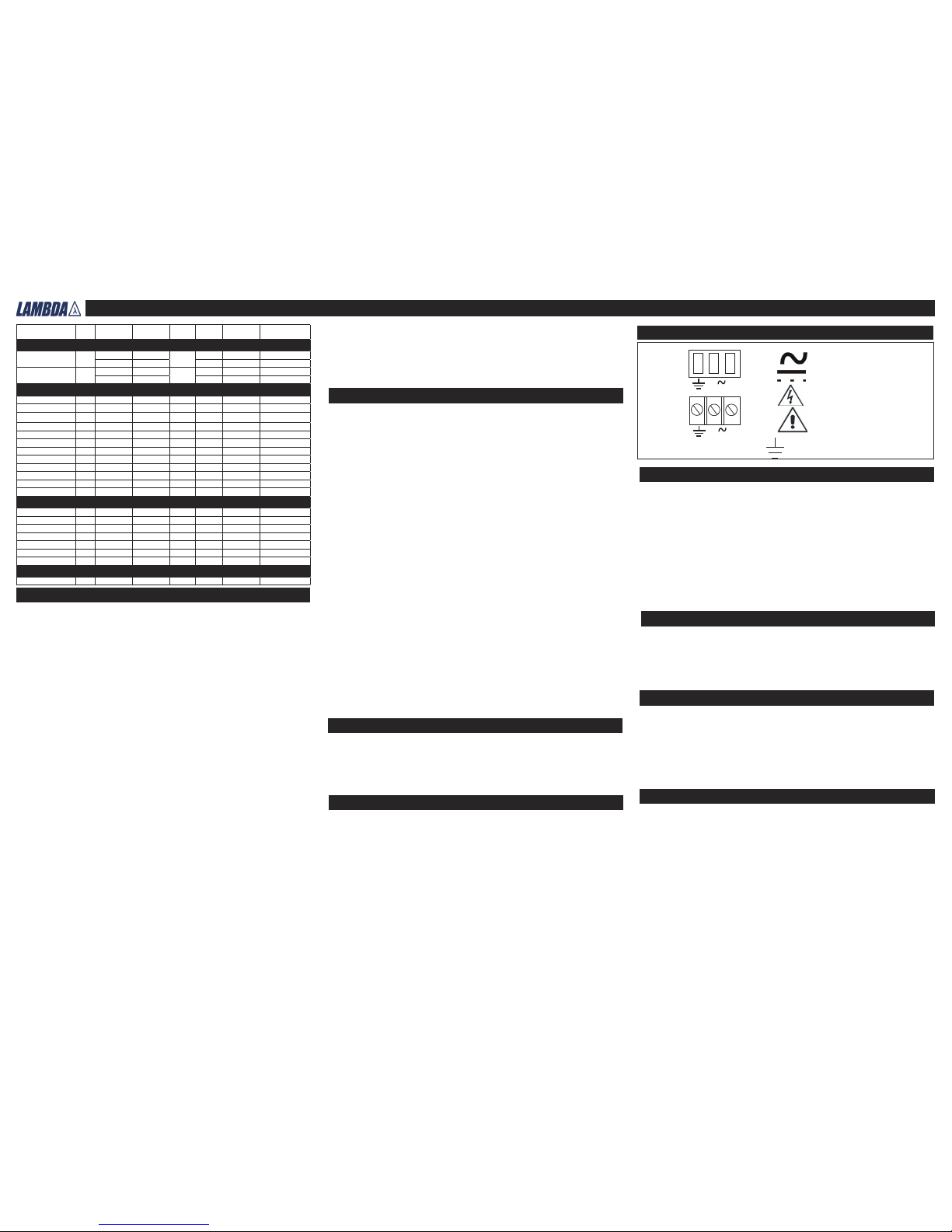
Level of insulation
Input markings and symbols
Terminal Block
Fast-ons
N L
L
N
alternating current (a.c.)
direct current (d.c.)
danger, shock hazard
caution, refer to supplementary documents.
Earth
L
Live
N
Neutral
Custom Model
Model: NS-THE/V9FSSF B/S 28E5HS (K90036)
Input: 90-264Vac, 47-63Hz
Maximum output: 28V, 25A, maximum output power: 700W
Page 3

Vega 900 Handbook
�
Part Number 17155
Primary Options
Specified Option Pin 5 Logic 0 Pin 6 Logic 1
Inhibit Outputs OFF Outputs OFF
Enable Outputs ON Outputs ON
Secondary Options
Module Good
Inhibit Anode
Mating input faston connectors
Brand Colour Wire size (awg) Part number Current rating
Amp Red 22 - 18 2-520407-2 15A
Amp Blue 16 - 14 3-520408-2 15A
Input Connections
Input tabs - 6.3mm x 0.8mm, tin plated brass, rated 15A. Internal fuse (F1) 16A/250V fast acting
HBC fuse 6.3x32mm
Input Screw Terminals: 6-32 screws with 8.25mm spacing between screw head centres. Screw
head diameter is 6.6mm.
Input IEC 320: Rated 10A/250Vac (15A/132Vac)
Connection details
Inhibit
Remote Sense +VE
Inhibit/Enable Anode
Remove Sense -VE
Inhibit/Enable
Share
Com-
Share
Module Good Collector
Remote Sense +VE
Analogue programming
(Voltage or resistive with respect to comman)
Module Good Emitter
Single output wide range programmable module
Inhibit/Enable Anode
Inhibit/Enable Cathode
0-32K resistance
Ω
0-5V external voltage prog.pin
Prog signal return
Inhibit/Enable Anode
Inhibit/Enable Cathode
0-5V current prog. pin
Prog. signal return
Prog. signal return
Transistor ON (saturated) when
module is GOOD.
Module is GOOD when output
voltage is between (88-96%) and
(104-112%) of its set voltage.
Max Vce 70V
Vsat <0.4V at
1mA current
Module good Collector
Module good Emmitter
Single output module digital option
TWIN Output Module ”R” Option
TWIN Output Module ”N” Option
Inhibit Anode
Remote Sense -VE
Inhibit Cathode
Remote Sense -VE
Inhibit Anode
Inhibit Cathode
Module Good Collector
Remote Sense +VE
Module Good
Module Good Collector
Remote Sense +VE
Module Good
CH1
CH2
Remote Sense +VE
Remote Sense +VE
Remote Sense -VE
Remote Sense -VE
C H 1
C H 2
Internally is a 390
resistor is series with
diode of an optocoupler. Drive
≥2mA to inhibit module (max
13mA).
INH A
INH C
390
VF=1.1V
Ω
Ω
Remote Sense Option
SINGLE Output Module ”N” Option
Remote Sense -VE
Inhibit Cathode
Module Good Collector
Share
Share
Inhibit Anode
Module Good Collector
Module Good Emitter
Internally is the output of an opto-isolated transistor.
Transistor “on”=AC + Temp O.K. Vce max = 30V Ic max =
5mA, 5mS warning of thermal shutdown or loss of AC.
Logic 0 = 0-0.8V. Logic 1 = 2.0 - 5.0V with respect to 0V (Pin 3)
AC + Temp Fail, E
AC + Temp OK
AC + Temp Fail, C
AC + Temp Fall, C
AC + Temp Fall, E
0V
Aux Voltage
INH/ENA Logic 0 (TTL Logic Levels)
INH/ENA Logic 1(TTL Logic Levels)
Pin 1
Pin 6
Maximum Torque Settings for Output Screw Terminals
M3 - 0.75Nm M4 - 1.5Nm M5 - 2.0Nm
Output Connections
Output Connector Ratings: Single slot, single output modules (B, C, L modules): Two 6.35mm
fast-ons per output each rated at 18A or M4 screw terminals rated at 35A. Single slot, twin output
modules (H modules); One 6.35mm fast-on per output rated at 18A or M3 screw terminals rated at
15A. Dual slot, single output modules (D, E modules): Two 9.5mm fast-ons per output each rated
at 32A, or M5 screw terminals rated at 90A
Special instructions for applications covered by IEC/EN/UL/CSA61010-1.
Whilst all individual module single outputs are classed as SELV outputs in accordance with IEC/EN/
UL/CSAEN60950-1 (<60Vdc or 42.4V peak) serried combinations of these modules may exceed
these values and become hazardous output voltages. For IEC/EN/UL/CSA61010-1 the equivalent
limits are 70Vdc, 33Vrms or 46.7V peak.
Under single fault conditions these limits are increased for IEC/EN/UL.CSA61010-1 and UL3101-1
to 140Vdc, 55Vrms or 78V peak. Provided these levels are not exceeded, the outputs are not
considered hazardous for IEC/EN/UL/CSA61010-1
DO NOT USE MOUNTING SCREWS WHICH PENETRATE THE UNIT BY MORE THAN 4.5 MM.
Weight 2 Kg dependent upon configuration.
Mechanical parameters
If the equipment is used in a manner not specified by the manufacturer, the protection
provided by the equipment may be impaired.
Applicable to products with L, R and T filter options only.
i) These products are designed for continuous operation within an overall enclosure, and must
be mounted such that access to the mains terminals isrestricted. See Clause 16, IEC/EN/UL/
CSA60601-1,
ii) These products are NOT suitable for use in the presence of flammable anaesthetic mixtures
with air or with oxygen or with nitrous oxide.
iii) These products are classed as ordinary equipment according to IEC/EN/UL/CSA60601-1 and
are NOT protected against the ingress of water.
iv) Connect only apparatus complying with IEC/EN/UL/CSA60601-1, to the signal ports.
v) Except for permanently installed equipment as defined in Clause 57.6 of IEC/EN/UL/
CSA60601-1, the overall equipment in which these products are installed must have double pole
fusing on the input mains supply or DC supply as appropriate. The products themselves have
single pole fusing in the live line or positive DC line as appropriate.
vi) Reference should be made to local regulations concerning the disposal of these products at
the end of their useful life.
Special instructions for medical applications (IEC/EN/UL/CSA60601-1)
Input Filter Options
Option Max. Leakage at 264VAC,63Hz RFI EN55022 Class
Standard 1.5mA max B/A
M 650uA max A
L 290uA max A
R 175uA max Above A
T 60uA max Above A
Note: When primary options EW or FW are fitted the above values increase 100uA
Page 4

Vega 900 Handbook
�
Part Number 17155
Right Angle Screw Terminal Input
IEC 320 (Switched) Input
Quick Connect (Faston) Input
Customer fixing
s
Customer Air and Fixing detail
Customer fixings are M4
Customer fixings are M4
Customer fixings are M4
CEL Part No. 17155 Issue 09,May 2006
Coutant Lambda Limited,
Kingsley Avenue,
Ilfracombe,
Devon, EX34 8ES.
Telephone - Sales and Service (01271) 856666.
Head Office and Works (01271) 856600.
Facsimile (01271) 864894.
WEBSITE: www.lambda-gb.com
Customer fixings are M4
 Loading...