


 Loading...
USER MANUAL
OPTex
07/2005
LP Part Number: 263 292
Document Code: A0507OPTex
U.S.A. |
|
JAPAN |
|
Lambda Physik USA, Inc. |
Lambda Physik Japan Co., Ltd. |
||
3201 West Commerical Blvd. |
German Industry Center |
||
Ft. Lauderdale, FL 33309, USA |
1-18-2 Hakusan, Midori-ku |
||
Tel.: |
+1 (954) 486-1500 |
Yokohama 226-0006, Japan |
|
|
|
||
|
1 (800) EXCIMER |
Tel.: |
+81 (45) 939-7848 |
Fax: |
+1 (954) 486-1501 |
Fax: |
+81 (45) 939-7849 |
eMail: |
marketingusa@lambdaphysik.com |
|
|
Internet: |
http://www.lambdaphysik.com/optex |
|
|
GERMANY |
Marubun Corp. |
||
Lambda Physik AG |
Marubun Daiya Bldg. |
||
Hans-Böckler-Strasse 12 |
8-1 Nihonbashi Odenmacho |
||
D - 37079 Göttingen, Germany |
Chuo-ku, Tokyo 103-8577, Japan |
||
Tel.: |
+49 (551) 6938-0 |
Tel.: |
+81 (3) 3639-9811 |
Fax: |
+49 (551) 68691 |
Fax: |
+81 (3) 3662-1349 |
eMail: |
salesgermany@lambdaphysik.com |
|
|
CONTENTS
1INTRODUCTION
2LASER DEVICE FUNDAMENTALS
3SAFETY
4SPECIFICATIONS AND REQUIREMENTS
5INSTALLATION
6LASER CONTROL
7OPERATION
8MAINTENANCE
9TROUBLESHOOTING
10DIAGRAM SCHEMATICS LIST OF FIGURES INDEX
A0507OPTex
TABLE OF CONTENTS |
|
|
1 |
INTRODUCTION . . . . . . . . . . . . . . . . . . . . . . |
1 |
1.1 |
About this Manual . . . . . . . . . . . . . . . . . . . . . . . . . . |
1 |
1.1.1 Purpose, Availability and Use. . . . . . . . . . . . . . . . |
1 |
|
1.1.2 |
Intended Audience . . . . . . . . . . . . . . . . . . . . . . . . |
2 |
1.1.3Numbering of Chapters, Pages and Instructions . 2
1.2 |
Safety . . . . . . . . . . . . . . . . . . . . . . . . . . . . . . . . . . . |
. 3 |
1.2.1 |
Laser Safety Classification . . . . . . . . . . . . . . . . . |
. 3 |
1.2.2 |
Safety Information . . . . . . . . . . . . . . . . . . . . . . . |
. 3 |
1.2.3 |
Signal Words and Symbols in this Manual . . . . . |
. 3 |
1.3 |
Overview of Chapters . . . . . . . . . . . . . . . . . . . . . . |
. 5 |
1.4 |
Conversion Tables . . . . . . . . . . . . . . . . . . . . . . . . |
. 6 |
1.4.1 |
Measurements . . . . . . . . . . . . . . . . . . . . . . . . . . |
. 6 |
1.4.2 |
Temperatures . . . . . . . . . . . . . . . . . . . . . . . . . . . |
. 6 |
1.5 |
Patents and Trademarks. . . . . . . . . . . . . . . . . . . . |
. 7 |
1.5.1 |
Patents . . . . . . . . . . . . . . . . . . . . . . . . . . . . . . . . |
. 7 |
1.5.2 |
Trademarks . . . . . . . . . . . . . . . . . . . . . . . . . . . . |
. 9 |
1.6 |
Feedback Regarding Documentation . . . . . . . . . |
10 |
2 |
LASER DEVICE FUNDAMENTALS . . . . . . |
11 |
2.1 |
Excimer Laser . . . . . . . . . . . . . . . . . . . . . . . . . . . . |
11 |
2.1.1 |
The NovaTube® Innovation . . . . . . . . . . . . . . . . |
11 |
2.2 |
Laser Terminology According to ISO 11145. . . . |
12 |
2.3 |
Fundamental Design of the OPTex . . . . . . . . . . . |
13 |
2.4 |
Overview of the OPTex . . . . . . . . . . . . . . . . . . . . . |
14 |
2.5 |
Laser Control . . . . . . . . . . . . . . . . . . . . . . . . . . . . . |
17 |
2.6 |
Laser Tube . . . . . . . . . . . . . . . . . . . . . . . . . . . . . . . |
18 |
2.7 |
Thyratron . . . . . . . . . . . . . . . . . . . . . . . . . . . . . . . . |
20 |
2.8 |
Energy Monitor . . . . . . . . . . . . . . . . . . . . . . . . . . . |
21 |
2.9 |
Operating Modes . . . . . . . . . . . . . . . . . . . . . . . . . . |
21 |
LAMBDA PHYSIK - 07/2005 |
CONTENTS - I |

TABLE OF CONTENTS
2.10 |
Safety Systems of the OPTex. . . . . . . . . . . . . . . . |
23 |
2.10.1 Safety Interlock. . . . . . . . . . . . . . . . . . . . . . . . . . 24
2.10.2 Electronics Chamber . . . . . . . . . . . . . . . . . . . . . 24
2.10.3 Tube Chamber . . . . . . . . . . . . . . . . . . . . . . . . . . 24
3 |
SAFETY . . . . . . . . . . . . . . . . . . . . . . . . . . . . |
25 |
3.1 |
General Safety Aspects . . . . . . . . . . . . . . . . . . . . |
25 |
3.1.1 |
Basic Operation and Designated Use . . . . . . . . |
25 |
3.1.2 |
Organizational Measures . . . . . . . . . . . . . . . . . . |
26 |
3.1.3 |
Selection and Qualification of Personnel |
|
|
- Basic Responsibilities . . . . . . . . . . . . . . . . . . . |
27 |
3.1.4Safety Instructions Governing
|
Specific Operational Phases . . . . . . . . . . . . . . . |
28 |
3.2 |
Specific Safety Aspects . . . . . . . . . . . . . . . . . . . . |
30 |
3.2.1 |
Physical Hazards . . . . . . . . . . . . . . . . . . . . . . . . |
31 |
3.2.2 |
Personnel Safety . . . . . . . . . . . . . . . . . . . . . . . . |
35 |
3.2.3 |
Constructive Safety Features . . . . . . . . . . . . . . . |
42 |
3.3 |
Safety Compliance List. . . . . . . . . . . . . . . . . . . . . |
46 |
3.4 |
Labels . . . . . . . . . . . . . . . . . . . . . . . . . . . . . . . . . . . |
47 |
3.4.1 |
Label Location Diagrams . . . . . . . . . . . . . . . . . . |
48 |
3.4.2 |
Description of the Labels and Safety Labels . . . |
50 |
4 |
SPECIFICATIONS AND REQUIREMENTS. 51 |
|
4.1 |
Specifications . . . . . . . . . . . . . . . . . . . . . . . . . . . . |
51 |
4.2 |
Physical Dimensions . . . . . . . . . . . . . . . . . . . . . . |
52 |
4.3 |
Electrical Power Supply . . . . . . . . . . . . . . . . . . . . |
54 |
4.4 |
Remote Control Interlock . . . . . . . . . . . . . . . . . . . |
55 |
4.5 |
Controller Requirements . . . . . . . . . . . . . . . . . . . |
56 |
4.6 |
External Trigger In and Pre-Trigger Out . . . . . . . |
57 |
4.6.1 |
TWE Trigger Converter (Option) . . . . . . . . . . . . |
57 |
CONTENTS - II |
User Manual OPTex |

A0507OPTex
TABLE OF CONTENTS
4.7 |
Gas Requirements. . . . . . . . . . . . . . . . . . . . . . . . . |
59 |
4.7.1 |
Gas Lines . . . . . . . . . . . . . . . . . . . . . . . . . . . . . . |
60 |
4.7.2 |
Pressure Regulators. . . . . . . . . . . . . . . . . . . . . . |
60 |
4.7.3 |
Gas Cabinets . . . . . . . . . . . . . . . . . . . . . . . . . . . |
60 |
4.7.4 |
Gases Required (Premix). . . . . . . . . . . . . . . . . . |
61 |
4.7.5 |
Optimum Gas Mixtures (Single Gases) . . . . . . . |
62 |
4.8 |
Air Intake and Exhaust . . . . . . . . . . . . . . . . . . . . . |
63 |
4.9 |
Environmental Conditions . . . . . . . . . . . . . . . . . . |
64 |
4.10 |
Space Requirements. . . . . . . . . . . . . . . . . . . . . . . |
64 |
5 |
INSTALLATION . . . . . . . . . . . . . . . . . . . . . . |
65 |
5.1 |
Site Preparation. . . . . . . . . . . . . . . . . . . . . . . . . . . |
65 |
5.2 |
Transport Locks . . . . . . . . . . . . . . . . . . . . . . . . . . |
66 |
5.3 |
Insert Safety Plug . . . . . . . . . . . . . . . . . . . . . . . . . |
66 |
5.4 |
Connect Controller . . . . . . . . . . . . . . . . . . . . . . . . |
67 |
5.4.1 |
Connecting the PC (PC-Powered Convertor). . . |
67 |
5.4.2Connecting the PC (Mains-Powered Convertor) 69
5.5 |
Software Installation . . . . . . . . . . . . . . . . . . . . . . . |
70 |
5.6 |
Connect External Trigger . . . . . . . . . . . . . . . . . . . |
71 |
5.7 |
Connect Power Supply Line. . . . . . . . . . . . . . . . . |
72 |
5.8 |
Connect Exhaust Line (Option) . . . . . . . . . . . . . . |
73 |
5.9 |
Gas Lines Installation . . . . . . . . . . . . . . . . . . . . . . |
74 |
5.9.1 |
Remarks Regarding Gas Line Installation . . . . . |
74 |
5.9.2 |
Connect Gas Supply Lines. . . . . . . . . . . . . . . . . |
75 |
5.10Connect Beam Guidance System
|
(for F2 Version) . . . . . . . . . . . . . . . . . . . . . . . . . . . |
77 |
5.11 |
New Gas Fill . . . . . . . . . . . . . . . . . . . . . . . . . . . . . . |
78 |
6 |
LASER CONTROL. . . . . . . . . . . . . . . . . . . . |
79 |
6.1 |
Laser Control Software. . . . . . . . . . . . . . . . . . . . . |
79 |
6.1.1 |
Start Laser Control Software . . . . . . . . . . . . . . . |
79 |
6.1.2 |
Exit Laser Control Software . . . . . . . . . . . . . . . . |
80 |
6.1.3 |
Laser Control Screen . . . . . . . . . . . . . . . . . . . . . |
80 |
6.2 |
Service Software . . . . . . . . . . . . . . . . . . . . . . . . . . |
88 |
6.3 |
Logbook file . . . . . . . . . . . . . . . . . . . . . . . . . . . . . . |
88 |
LAMBDA PHYSIK - 07/2005 |
CONTENTS - III |

TABLE OF CONTENTS
7 |
OPERATION . . . . . . . . . . . . . . . . . . . . . . . . |
89 |
7.1 |
Check Beam Path . . . . . . . . . . . . . . . . . . . . . . . . |
. 89 |
7.2 |
Start-Up Laser Device . . . . . . . . . . . . . . . . . . . . . |
. 90 |
7.2.1 |
Turn On Gas Supply. . . . . . . . . . . . . . . . . . . . . |
. 90 |
7.2.2 |
Switch On Laser Device and Controller . . . . . . |
. 92 |
7.3 |
Methods of Operation . . . . . . . . . . . . . . . . . . . . . |
. 95 |
7.3.1 |
Laser Operation Modes . . . . . . . . . . . . . . . . . . |
. 96 |
7.3.2 |
Gas Modes . . . . . . . . . . . . . . . . . . . . . . . . . . . . |
100 |
7.4 |
Start and Stop Laser Operation . . . . . . . . . . . . . |
101 |
7.4.1 |
Start Laser Operation . . . . . . . . . . . . . . . . . . . . |
101 |
7.4.2 |
Stop Laser Operation . . . . . . . . . . . . . . . . . . . . |
103 |
7.5 |
Shut-Down Laser Device . . . . . . . . . . . . . . . . . . |
103 |
7.5.1 |
Switch Off Laser Device and Controller . . . . . . |
103 |
7.5.2 |
Turn Off Laser Gases. . . . . . . . . . . . . . . . . . . . |
104 |
8 |
MAINTENANCE . . . . . . . . . . . . . . . . . . . . . |
107 |
8.1 |
Laser Logbook. . . . . . . . . . . . . . . . . . . . . . . . . . . |
108 |
8.2 |
Laser Device Design . . . . . . . . . . . . . . . . . . . . . . |
108 |
8.3 |
Maintenance Schedule . . . . . . . . . . . . . . . . . . . . |
109 |
8.4 |
Gas Line Maintenance . . . . . . . . . . . . . . . . . . . . |
110 |
8.4.1 |
Flush Premix Gas Line (External Flushing) . . . |
110 |
8.4.2 |
Exchange Premix Gas Cylinder . . . . . . . . . . . . |
112 |
8.4.3 |
Exchange Inert Gas Cylinder . . . . . . . . . . . . . . |
114 |
8.5 |
New Gas Fill . . . . . . . . . . . . . . . . . . . . . . . . . . . . . |
116 |
8.6 |
Windows Maintenance . . . . . . . . . . . . . . . . . . . . |
118 |
8.6.1 |
Windows Exchange . . . . . . . . . . . . . . . . . . . . . |
119 |
8.6.2 |
Windows Alignment . . . . . . . . . . . . . . . . . . . . . |
127 |
8.6.3Disassembling / Assembling Window Mounts . 132
8.6.4 |
Windows Cleaning . . . . . . . . . . . . . . . . . . . . . . |
136 |
8.7 |
Halogen Filter Maintenance . . . . . . . . . . . . . . . . |
140 |
8.7.1 |
Halogen Filter Exchange . . . . . . . . . . . . . . . . . |
140 |
8.7.2 |
Halogen Filter Disposal . . . . . . . . . . . . . . . . . . |
142 |
8.8 |
Energy Monitor Calibration . . . . . . . . . . . . . . . . |
143 |
CONTENTS - IV |
User Manual OPTex |

TABLE OF CONTENTS
9 |
TROUBLESHOOTING . . . . . . . . . . . . . . . . |
147 |
9.1 |
Fuses . . . . . . . . . . . . . . . . . . . . . . . . . . . . . . . . . . |
148 |
9.2 |
Possible Problems and Solutions . . . . . . . . . . . |
149 |
9.2.1 |
Power-Up Error . . . . . . . . . . . . . . . . . . . . . . . . |
149 |
9.2.2 |
Statical Errors. . . . . . . . . . . . . . . . . . . . . . . . . . |
150 |
9.2.3 |
Operation Errors. . . . . . . . . . . . . . . . . . . . . . . . |
152 |
10 |
DIAGRAM SCHEMATICS . . . . . . . . . . . . . |
155 |
10.1 |
Gas Flow Diagram . . . . . . . . . . . . . . . . . . . . . . . . |
155 |
10.2 |
Electrics Diagram . . . . . . . . . . . . . . . . . . . . . . . . |
156 |
10.3 |
Fiber Optic Light Waveguide Diagram . . . . . . . |
157 |
10.4 |
Safety Circuits Diagram . . . . . . . . . . . . . . . . . . . |
158 |
|
LIST OF FIGURES . . . . . . . . . . . . . . . . . . . |
159 |
|
INDEX. . . . . . . . . . . . . . . . . . . . . . . . . . . . . |
161 |
A0507OPTex
LAMBDA PHYSIK - 07/2005 |
CONTENTS - V |

TABLE OF CONTENTS
CONTENTS - VI |
User Manual OPTex |
A0507OPTex
About this Manual
1 INTRODUCTION
This chapter outlines:
–the purpose as well as the necessary availability and use of the instruction manual,
–the persons, for whom the instruction manual is intended,
–how the instruction manual is organized,
–the use of signal words and safety signs in the instruction manual,
–the contents of each chapter.
1.1 |
About this Manual |
1.1.1 |
Purpose, Availability and Use |
|
This instruction manual is intended to familiarize the user with the |
|
OPTex and its designated use. |
The instruction manual contains important information to installing and operate the OPTex safely, properly and most efficiently. Observing these instructions helps to avoid danger, reduce repair costs and downtimes and increase the reliability and lifetime of the OPTex.
The instruction manual must always be available wherever the OPTex is in use.
The instruction manual must be read and applied by any person in charge of carrying out work with and on the OPTex, e.g.:
– operation including setting up, troubleshooting in the course of work, removal of production waste, care and disposal of consumables.
– maintenance (servicing, inspection, repair) and/or
– transport.
The instruction manual is to be supplemented by the respective national rules and regulations for accident prevention and environmental protection.
LAMBDA PHYSIK - 07/2005 |
1 |

INTRODUCTION
1.1.2 |
Intended Audience |
This manual is intended for:
–Operators, who have completed the OPTex Basic Operations course. An operator operates the OPTex excimer laser in normal day-to-day operations.
–Process engineers, who have completed the OPTex Advanced Operations course. A process engineer prepares jobs for production and other purposes and monitors production quantity and quality.
–Any reader who wishes to acquire general knowledge of the OPTex excimer laser.
1.1.3 |
Numbering of Chapters, Pages and Instructions |
The pages of this manual are numbered continuously. The page number appears in the lower outside corner of every page.
The chapters are numbered continuously. The name of the chapter appears in the upper outside corner of every even page, the name of the main section appears in the upper outside corner of the corresponding odd page.
Each chapter ends with an even page number. Consequently, certain even pages at the ends of chapters will be intentionally left blank.
Each step within a procedure is sequentially numbered.
2 |
User Manual OPTex |

A0507OPTex
Safety
1.2 |
Safety |
1.2.1 |
Laser Safety Classification |
|
Lasers and laser systems are classified according to their relative |
|
hazards. These classifications are found in the American National |
|
Standards for the Safe Use of Lasers (ANSI Z 136.1-1986), |
|
FDA 21 CFR 1040.10 and 1040.11 and IEC-825. |
|
Within this classification, the OPTex excimer laser is a class IV |
|
(high power) laser. It must be regarded as a potential hazard to |
|
the human operator. When connected to a correspondingly |
|
configured beam guidance system, the OPTex becomes a class I laser |
|
device. |
|
The laser beam must also be regarded as a potential fire hazard. |
1.2.2 |
Safety Information |
|
Chapter 3 (Safety) describes the physical hazards related to the laser |
|
device, the means of protection against these hazards and the safety |
|
features incorporated in the design of the laser device. |
|
The Safety Chapter must be read by all persons entrusted with any |
|
sort of work on the OPTex excimer laser device. |
|
Never start to follow the procedures detailed in this manual |
|
unless you have read and fully understood the information given |
|
in the Safety Chapter. |
1.2.3 |
Signal Words and Symbols in this Manual |
|
Contained within this manual are sections in which particular hazards |
|
are defined or special attention is drawn to particular conditions. These |
|
are indicated with signal words in accordance with ANSI Z-535.2-1991 |
|
and safety symbols (pictorial hazard alerts) in accordance with ANSI |
|
Z535.3-1991. The signal words are defined in section 1.2.3.1 of this |
|
manual and the safety symbols in section 1.2.3.2. |
1.2.3.1 |
Signal Words |
|
Four signal words are used in this manual: DANGER, WARNING, |
|
CAUTION and NOTE. The signal words DANGER, WARNING and |
|
CAUTION designate the degree or level of hazard: |
DANGER
Indicates an imminently hazardous situation which, if not avoided, will result in death or serious injury.
LAMBDA PHYSIK - 07/2005 |
3 |

INTRODUCTION
|
WARNING |
|
Indicates a potentially hazardous situation which, if not |
|
avoided, could result in death or serious injury. |
|
CAUTION |
|
Indicates a potentially hazardous situation which, if not avoided, |
|
may result in minor or moderate injury. It is also used to alert |
|
against unsafe practices that may result in property damage. |
|
Use of the signal word ”NOTE”: |
|
NOTE |
|
Used to define sections, where particular attention should be paid |
|
to ensure efficient operation or servicing of the laser device. |
1.2.3.2 |
Symbols |
|
The signal words DANGER, WARNING, and CAUTION are always |
|
emphasized with a safety symbol. These safety symbols are used to |
|
indicate special hazards. They are used regardless of the hazard level: |
This symbol is combined with one of the signal words DANGER, WARNING or CAUTION to indicate a hazardous situation caused by laser radiation.
This symbol is combined with one of the signal words DANGER, WARNING or CAUTION to indicate a hazardous situation caused by electricity.
This symbol is combined with one of the signal words DANGER, WARNING or CAUTION to indicate a hazardous situation caused by toxic substances.
This symbol is combined with one of the signal words DANGER, WARNING or CAUTION to indicate a hazardous situation caused by flammable substances.
This symbol is combined with one of the signal words DANGER, WARNING or CAUTION to indicate a hazardous situation caused by circumstances other than those described above.
4 |
User Manual OPTex |

Overview of Chapters
1.3 |
Overview of Chapters |
|
|
• |
Chapter 1 (this chapter). |
|
• |
Chapter 2 provides the reader with a short overview of system |
|
|
elements and a description of different subsystems. It introduces |
|
|
fundamental operational concepts, such as running modes, as well |
|
|
as familiarizing the reader with organization and function of the |
|
|
system. |
|
• |
Chapter 3 explains safety and provides an overview of safety signs |
|
|
and identification labels. Described are the main physical hazards as |
|
|
well as personal and constructional precautions. It is essential that |
|
|
you read this chapter before performing any task on the OPTex. |
|
• |
Chapter 4 describes the specifications, installation requirements, |
|
|
conditions of transport and operation and the accessories delivered |
|
|
with the OPTex. |
|
• |
Chapter 5 describes the installation of the OPTex. |
|
• |
Chapter 6 describes the laser control and service software and its |
|
|
application in the operation of the OPTex. |
|
• |
Chapter 7 contains instructions on how to start and operate the |
|
|
OPTex. |
|
• |
Chapter 8 describes fundamental maintenance routines, which can |
|
|
be performed by instructed operators. |
|
• |
Chapter 9 explains what action the operator can take when errors |
|
|
occur and how to trace errors. |
|
• |
Chapter 10 gives an overview of wiring diagrams and schematics. |
|
• |
The last pages of this manual include a list of figures and a index. |
A0507OPTex
LAMBDA PHYSIK - 07/2005 |
5 |

INTRODUCTION
1.4 |
Conversion Tables |
||
1.4.1 |
Measurements |
|
|
|
Listed below are the units of measure used in this manual and their |
||
|
equivalents according to the SI standard: |
||
|
1 meter (m) |
= |
39.37 inches (in) |
|
1 meter (m) |
= |
3.28 feet (ft) |
|
1 centimeter (cm) |
= |
0.3937 inch (in) |
|
1 square meter (m²) |
= 1,550 square inches (in²) |
|
|
1 square meter (m²) |
= 10.76 square feet (ft²) |
|
|
1 cubic meter (m³) |
= 35.31 cubic feet (ft³) |
|
|
1 liter (l) |
= 0.264 US gallons (gal) |
|
|
1 kilogram (kg) |
= 2.20 US pounds (lbs) |
|
|
1 bar |
= |
100,000 Pascal (Pa) |
|
100,000 Pascal (Pa) |
= |
14.50 pounds force |
|
|
|
per square inch (lbf/in²) |
1.4.2 |
Temperatures |
|
|
The temperatures in this manual are primarily indicated in degrees celsius (° C).
To convert °C to °F; multiply by 9, divide by 5 and add 32.
To convert °F to °C; subtract 32, multiply by 5, divide by 9.
As a guide, we have converted below some temperature values from °C to °F:
-10 °C |
= |
14 |
°F |
|
0 |
°C |
= |
32 |
°F |
5 |
°C |
= |
41 |
°F |
16 |
°C |
= |
61 |
°F |
20 |
°C |
= |
68 |
°F |
38 |
°C |
= |
100 |
°F |
100 |
°C |
= |
212 |
°F |
6 |
User Manual OPTex |
A0507OPTex
|
|
Patents and Trademarks |
1.5 |
Patents and Trademarks |
|
1.5.1 |
Patents |
|
|
Lambda Physik GmbH is owner of the following patents: |
|
|
Germany: P 32 12 928.9 |
“Entladungsgepumpter Laser” |
|
US Patent # 4,534,034 |
“Discharge-pumped laser” |
|
Germany: P 33 35 690.4 |
“Vorrichtung zum Erzeugen von |
|
|
Hochleistungs-Hochspannungsimpulsen |
|
|
hoher Wiederholfrequenz” |
|
Germany: P 38 17145.7 |
“Elektrode für gepulste Gaslaser und ihre |
|
|
Verwendung” |
|
Germany: G 88 17 197.3 |
“Elektrode für gepulste Gaslaser” |
|
US Patent # 4,860,300 |
“Electrode for pulsed gas lasers” |
|
Germany: P 37 14 503.7 |
“Steuerschaltung für einen gepulsten |
|
|
Gaslaser und Verfahren zum |
|
|
Initialisieren der Steuerschaltung” |
|
US Patent #4,916,707 |
“Control circuit for a pulsed gas laser” |
|
US Patent # 4,993,042 |
“Device for mounting a window on a gas |
|
|
discharge laser” |
|
US Patent # 4,980,894 |
“Ignitor for the preionization of a gas |
|
|
discharge laser” |
|
US Patent # 4,951,295 |
“Preionization means for a gas discharge |
|
|
laser” |
|
Germany: G 8906 627.8 |
“Vorrichtung zum Reinigen von |
|
|
Lasergas” |
Germany: P 40 03 841.6-09 “Laserresonator”
US Patent #5,220,574 |
“Excimer laser with hydrogen chloride |
|
and method for producing hydrogen |
|
chloride for an excimer laser” |
Japan 1 991 984 |
“Excimer laser with hydrogen chloride |
|
and method for producing hydrogen |
|
chloride for an excimer laser” |
Germany: P 42 06 803.7-09 “Verfahren zum Nachfüllen von
Halogengas in das Gasreservoir eines
Excimerlasers”
US Patent # 5,396,514 |
“Excimer laser comprising a gas |
|
reservoir and a collecting receptacle and |
|
a method of refilling the gas reservoir of |
|
the laser” |
Germany: G 92 08 936.4 |
“Laserresonator” |
LAMBDA PHYSIK - 07/2005 |
7 |

INTRODUCTION
Germany: P 42 33 634.1 “Elektroden für die Entladungseinheit eines Excimerlasers”
US Patent # 5,347,532 “Laser having at least one anode and one cathode for preionization and/or discharge”
Japan: Hei 5-262 989/93 “Laser having at least one anode and one cathode for preionization and/or discharge”
US Patent # 4,977,573 “Excimer laser output control device”
US Patent # 4,611,270 “Method and means of controlling the output of a pulsed laser”
Germany: P 43 35 079.8-33 “Elektroden in einer Fluor enthaltenden Entladungseinheit eines gepulsten Gasentladungslasers”
Germany: G 93 20 768.9 |
“Elektroden in einer Fluor enthaltenden |
|
Entladungseinheit eines gepulsten |
|
Gasentladungslasers” |
Germany: G 94 01 808.1 |
“Vorrichtung zum Regeln der Temperatur |
|
von Lasergas, insbesondere eines |
|
Excimerlasers” |
Germany: 295 20 820.1 |
“Laserröhre für halogenhaltige |
|
Gasentladungslaser” |
US Patent # 4,611,327 |
“Gas transport laser system” |
US Patent # 4,549,091 |
“Electrical excitation circuit for gas laser” |
US Patent # 4,393,505 |
“Gas discharge laser having a buffer gas |
|
of neon” |
US Patent # 4,340,968 |
“Rare gas hydrogen-halide excimer laser |
|
with hydrogen additive” |
Germany P 44 00 345.5 |
“Vorrichtung für die Reinigung von |
|
Lasergas” |
8 |
User Manual OPTex |

Patents and Trademarks
1.5.2 |
Trademarks |
|
|
LAMBDA PHYSIK |
is a registered trademark of Lambda |
|
|
Physik AG |
the Lambda Physik logo is a registered trademark of Lambda Physik AG
OPTex |
is a trademark of Lambda Physik AG |
NovaTube |
is a registered trademark of Lambda |
|
Physik AG |
Gyrolok |
is a registered trademark of Hoke Inc., |
|
NJ, USA |
Microsoft, MS, |
are registered trademarks of Microsoft |
Windows, Windows 95 and |
Corporation in USA and other countries |
Windows NT |
|
IBM |
is a registered trademark of |
|
International Business Machines, Inc. |
A0507OPTex
LAMBDA PHYSIK - 07/2005 |
9 |

INTRODUCTION
1.6 |
Feedback Regarding Documentation |
If you have any comments regarding the documentation provided to you, please contact us.
When you contact us, please provide us with
–The document code
–The date of issue
–The page number, section number and, where applicable, the procedure step number
–A description of any errors
–A proposal for improvements
Feedback Address |
|
documentation@lambdaphysik.com |
|
Post |
Lambda Physik AG |
|
Documentation Comments |
|
Hans-Böckler-Straße 12 |
|
D-37079 Göttingen |
|
Germany |
Telefax |
+49 551 68691 |
10 |
User Manual OPTex |
Excimer Laser
2 |
LASER DEVICE |
|
FUNDAMENTALS |
This chapter briefly describes the most important features, functions, and subassemblies of a Lambda Physik excimer laser. This background information will ease your understanding of the information contained in the subsequent chapters.
The information in this chapter does not enable you to operate or service the OPTex excimer laser.
Never switch on or attempt to operate or service the OPTex before reading, understanding and fully familiarizing yourself with Chapter 3 of this manual (Safety)!
2.1 |
Excimer Laser |
|
Excimer lasers take their name from the exci ted state dimers from |
|
which lasing occurs. The most important excimers are rare gas halides |
|
such as Argon Fluoride (ArF), Krypton Fluoride (KrF), Xenon Chloride |
|
(XeCl) and Xenon Fluoride (XeF). These produce intense UV light |
|
(U ltra V iolet) on distinct spectral lines between 157nm and 351nm. |
2.1.1 |
The NovaTube® Innovation |
All Lambda Physik excimer lasers use the NovaTube® technology. The NovaTube® has been conceived to virtually eliminate the effects of corrosion and contamination. To ensure strict adherence to these design objectives, all laser tube components are assembled in a clean-room. Optimized electrode materials combined with an improved preionization scheme minimizes electrode erosion. These major improvements in laser tube technology lead to an increased laser tube lifetime.
A0507OPTex
LAMBDA PHYSIK - 07/2005 |
11 |

LASER DEVICE FUNDAMENTALS
2.2 |
Laser Terminology According to |
|
ISO 11145 |
ISO 11145 (“Optics and Optical Instruments - Lasers and Laser Related Equipment - Vocabulary and Symbols”) contains a list of laser terminology.
To prevent misunderstandings, this manual strictly differentiates between “laser” and “laser device” (see Figure 1). Thus “Start laser device” means that the power is off and shall be turned on. To “start the laser” means to switch on the laser beam and start lasing.
Laser Unit |
Laser Assembly |
Laser Device |
Laser |
|
Workpiece |
|
Mirrors, Lenses, ... |
Telescope, |
|
Focussing, ... |
||
|
||
Supply Units |
|
|
Power, Cooling, ... |
|
|
Measuring and |
Handling Systems |
|
Control Unit |
||
|
Robotics, Workpiece |
|
|
Positioning |
Figure 1: Laser components according to ISO 11145
Definitions: |
|
Laser |
Lasers consist of an amplifying |
|
medium capable of emitting coherent |
|
radiation with wavelengths up to 1 mm |
|
by means of stimulated emission. |
Laser Device |
A laser, where the radiation is |
|
generated, together with essential |
|
additional facilities (e.g. cooling, |
|
power and gas supply) that are |
|
necessary to operate the laser. |
Laser Assembly |
Laser device together with specific, |
|
normally optical, mechanical and/or |
|
electrical system components for |
|
beam handling and forming. |
Laser Unit |
One ore more laser assemblies |
|
together with handling, measurement |
|
and control systems. |
12 |
User Manual OPTex |
Fundamental Design of the OPTex
2.3 |
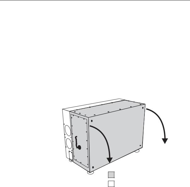
Fundamental Design of the OPTex |
The OPTex is provided with all required power supply and control units. One-phase mains power supply with protective earth as well as Premix and Inert gas supply are sufficient for safely and ease operation. Only a few modules are to be checked and serviced within determined periods. The maintenance schedule is shown in Section 8.3 on page 109.
The OPTex is the most compact Lambda Physik excimer laser device. To ensure fail-safe operation and ease-of-service, the laser device housing is divided into two separate chambers containing the internal components; designated as the tube chamber and the electronics chamber.
A0507OPTex
|
|
|
|
|
|
l |
|
|
|
|
|
e |
|
|
|
|
|
n |
|
|
|
|
|
a |
|
|
|
|
|
kp |
|
|
|
|
|
c |
|
|
|
|
|
a |
|
|
|
|
|
|
B |
|
|
|
|
|
|
Tiltable by 90° as indicated. Feet to be relocated in recesses on back panel.
Tube chamber
Electronics chamber
Figure 2: Fundamental design of the OPTex
To enable space at the installation site to be optimally utilized, the laser device can be installed on its back or on its bottom panel: recesses for the feet are provided in both panels.
The installation position (upright or flat) and the beam exit side are set at the factory. In this manual, we assume that the laser device is to be installed on its bottom panel (upright position). The beam is to exit from the aperture on the right-hand side (shown in Figure 2 and in Figure 3 on page 14). The gas and power connections are situated on the left-hand side (see Figure 4 on page 15).
LAMBDA PHYSIK - 07/2005 |
13 |

LASER DEVICE FUNDAMENTALS
2.4 |
|
Overview of the OPTex |
||
A |
B |
C |
D |
E |
INTERLOCK
|
|
|
e |
x |
|
|
T |
|
|
|
P |
|
|
|
O |
|
|
|
|
|
|
|
|
232 RS
M L K I H G F
Figure 3: Right side and front of the OPTex
Key to Figure 3:
AExhaust electronics chamber
BBeam exit aperture (for F2 version with beam guidance system connector)
CRecesses for feet (alternative)
DKey switch
EFront service panel
FHeight adjustable feet
GRight-hand service panel
HGas connection valve, Inert (alternative)
IGas connection valve, Premix (alternative)
KTrigger in / Pre trigger out connector (alternative)
LOptical RS232 connector (alternative)
MInterlock connector (alternative)
14 |
User Manual OPTex |

A0507OPTex
Overview of the OPTex
A
PRE MIX |
INERT |
B |
C |
D |
E |
F |
G |
|
POWER ON |
|
|
|
|
|
FUSE 2x6.3 W |
LASER EMISSION |
|
|
|
|
|
INDICATOR |
|
|
|
|
RS 232 |
INTERLOCK |
|
|
|
P O N M L K I H
Figure 4: Left side and top of the OPTex
Key to Figure 4:
AExhaust tube chamber
BAir intake tube chamber
CKey switch
DPower ON light
EAir intake electronics chamber
FLaser tube
GTop service panel
HLaser radiation warning lamp
IInterlock connector
KOptical RS232 connector
LTrigger in / Pre trigger out connector
MMains socket with main fuses
NLeft-hand service panel
OGas connection valve, Inert
PGas connection valve, Premix
LAMBDA PHYSIK - 07/2005 |
15 |

LASER DEVICE FUNDAMENTALS
H I K L
A
G
B
F E D C
Figure 5: Electronics chamber (with service panel removed)
Key to Figure 5:
ATrigger board
BThyratron supply board
CHigh voltage power supply module
DGas supply unit
ELaser control unit
FVacuum pump
GHalogen filter
HMains filter
IMains power supply unit
KTransformer
LPower distribution unit
16 |
User Manual OPTex |

Laser Control
2.5 |
Laser Control |
The OPTex is controlled through an integral control device, known as the laser control unit (CLS). This communicates with decentralized submodules that perform dedicated functions (e.g. laser pulse triggering).
Communication between the laser control unit and the decentralized modules occurs through fiber optic light waveguides (FOLs). As the FOLs do not pick up or transmit electromagnetic interference (EMI), they provide a secure noise-free communication link. This is of considerable importance as the fast high voltage (HV) discharges required with excimer lasers create a high level of EMI.
The laser control software is stored on a flash prom mounted on the laser control unit. This is interfaced to the operator through either the optical RS232 in case of an OEM subassembly or through an operating panel simulated on an PC (the software is provided). In the following description “PC” also means Laptop.
A0507OPTex
Figure 6: OPTex controlled through a Laptop
The OEM device’s controller unit or the existing PC is connected to the laser control unit in the laser device through an optical RS232 interface. To convert the electrical signals emitted by the PC into the optical signals required by the laser control unit and vice-versa, a RS232 optical interface adapter is connected to a serial port on the PC. This adapter is supplied as standard when operation through a PC is specified.
LAMBDA PHYSIK - 07/2005 |
17 |

LASER DEVICE FUNDAMENTALS
2.6 |
Laser Tube |
|
|
|
|
|
|||||||||||||||||
|
The NovaTube® can be considered as the motor of the laser. Figure 7 |
||||||||||||||||||||||
|
shows a cross section of the longitudinally symmetrical laser tube. |
||||||||||||||||||||||
|
|
A |
|
|
B |
||||||||||||||||||
|
|
|
|
|
|
|
|
|
|
|
|
|
|
|
|
|
|
|
|
|
|
|
|
|
|
|
|
|
|
|
|
|
|
|
|
|
|
|
|
|
|
|
|
|
|
|
|
|
|
|
|
|
|
|
|
|
|
|
|
|
|
|
|
|
|
|
|
|
|
|
|
|
|
|
|
|
|
|
|
|
|
|
|
|
|
|
|
|
|
|
|
|
|
|
|
|
|
|
|
|
|
|
|
|
|
|
|
|
|
|
|
|
|
|
|
|
|
|
|
|
|
|
|
|
|
|
|
|
|
|
|
|
|
|
|
|
|
|
|
|
|
|
|
|
|
|
|
|
|
|
|
|
|
|
|
|
|
|
|
|
|
|
|
|
|
|
|
|
|
|
|
|
|
|
|
|
|
|
|
|
|
|
|
|
|
|
|
|
|
|
|
|
|
|
|
|
|
|
|
|
|
|
|
|
|
|
|
|
|
|
|
|
|
|
|
|
|
|
|
|
|
|
|
|
|
|
|
|
|
|
|
|
|
|
|
|
|
|
|
|
|
|
|
|
|
|
|
|
|
|
|
|
|
|
|
|
|
|
|
|
|
|
|
C
D
Figure 7: Cross section of the laser tube
The laser tube (C) is the reservoir for the laser gas. The materials chosen allow the problem-free use of excimer gas mixtures. The material surfaces become coated with a layer of halogen metal complex. This process, resulting from a reaction between halogen (laser gas) and metal (material within tube), is called passivation. Passivation renders the material surfaces within the tube chemically inert to halogen.
A repetition of this process, known as re-passivation, is always required
–if the surface passivation has been damaged as a result of air entering the laser tube
–(with multigas version only) if a change from a Fluorine to a Chloride gas mixture is necessary
–when the laser device or laser tube has been transported or stored for longer periods.
18 |
User Manual OPTex |

Laser Tube
A high voltage discharge between the electrodes (A) transfers the energy to the excimer gas mixture (e. g. fluorine or krypton premix). In order to obtain a controlled, spark-free discharge, the laser gas has to be preionized, i. e. a sufficiently high density of free charged molecules has to be created between the electrodes. This is achieved with preionization pins (B) arranged along the main electrodes. The result is a homogeneous preionization of the laser gas. The switching of preionization and main discharge in series ensures a perfect synchronization between preionization and main discharge.
After the high-voltage discharge, thermal inhomogenities in the laser gas arise in the discharge area. Therefore, the gas volume in the discharge area has to be completely exchanged between two laser pulses. A transverse circulation fan (D) positioned within the laser tube causes the gas volume between the main electrodes to be completely replaced between two successive laser pulses. The circulation fan is driven externally via a magnetic coupling by a single-phase motor.
The energy efficiency of the excimer laser is to the order of 2%, i. e. the main part of the energy supplied has to be carried away in the form of heat. The gas heated up by the discharge is recooled to the correct operating temperature (approx. 40 °C or 104 °F) using environmental air.
The maintenance operations required during the lifetime of the NovaTube® are new gas fills and the exchange of the windows. To minimize downtimes, the windows should be stored as premounted units.
A0507OPTex
LAMBDA PHYSIK - 07/2005 |
19 |

LASER DEVICE FUNDAMENTALS
2.7 |
Thyratron |
The laser uses a simple hydrogen thyratron, a thermionic tube. It is used as an active switch to discharge the storage capacitors. The anode of the thyratron is connected to the charging voltage. The cathode is connected to ground. Between these two main electrodes is the control grid, which initiates the discharge (switching) of the thyratron.
As is also the case with conventional thermionic tubes, the cathode structure has to be heated in order to ensure sufficient emission of starting electrons. If the electron emission after a longer operating period is no longer sufficient to initiate switching of the thyratron, this can be corrected during the thyratron lifetime by increasing the heating power of the cathode. Hydrogen is necessary to provide a fast current increase and a high current intensity. However, as hydrogen is continually lost due to diffusion and metal erosion, the concentration of hydrogen has to be continually renewed. For this purpose, there is a reservoir structure (palladium) in the tube, in which a large quantity of hydrogen is stored. By heating the reservoir, hydrogen is released from the reservoir into the main thyratron. It should be noted, however, that too much hydrogen reduces the hold-off voltage between the electrodes of the thyratron to such a level that unwanted switching of the thyratron will take place even without the trigger pulse. On the other hand, if the partial hydrogen pressure in the thyratron is too low, the laser is unable to pulse. This is because there is no discharge in the thyratron due to a lack of charged particles.
The values for the two heating voltages, UH for the cathode heating and UR for the hydrogen reservoir voltage, are critical to the correct operation of the tube. The voltages are stabilized in a broad input voltage range in order to be unaffected by voltage fluctuations in the supply line (spikes). These values have to be altered during the total life of the thyratron to ensure proper switching of the tube.
20 |
User Manual OPTex |
Loading...