

Page 1
Sirius 250 Handbook Part Number 17132
Input Parameters
NOMINAL INPUT VOLTAGE RANGE 94.5 - 240VAC or 133-330VDC
MAX. INPUT VOLTAGE RANGE 85-264VAC or 120-360VDC
INPUT FREQUENCY 47-63Hz
MAXIMUM INPUT CURRENT 5A AC or 3.4A DC
INRUSH CURRENT <50 AMPS
Output Parameters
Adjustment and Derating.
The Sirius 250 series is designed to provide a max output power of 250W at
nominal output voltages. The following procedure must be used to ensure the
PSU is operated within its ratings:
a Calculate user power for each module (volts x amps).
b Add all the individual module powers together. The total power must not
exceed the value given in the following tables.
c Calculate secondary transformer turns x amps for each module. (See
outputs table for transformer secondary turns).
d Add all the module turns x amps together and this must not exceed 75AT.
e If necessary reduce the loading until the conditions are met, ie. power and
ampere-turns maxima.
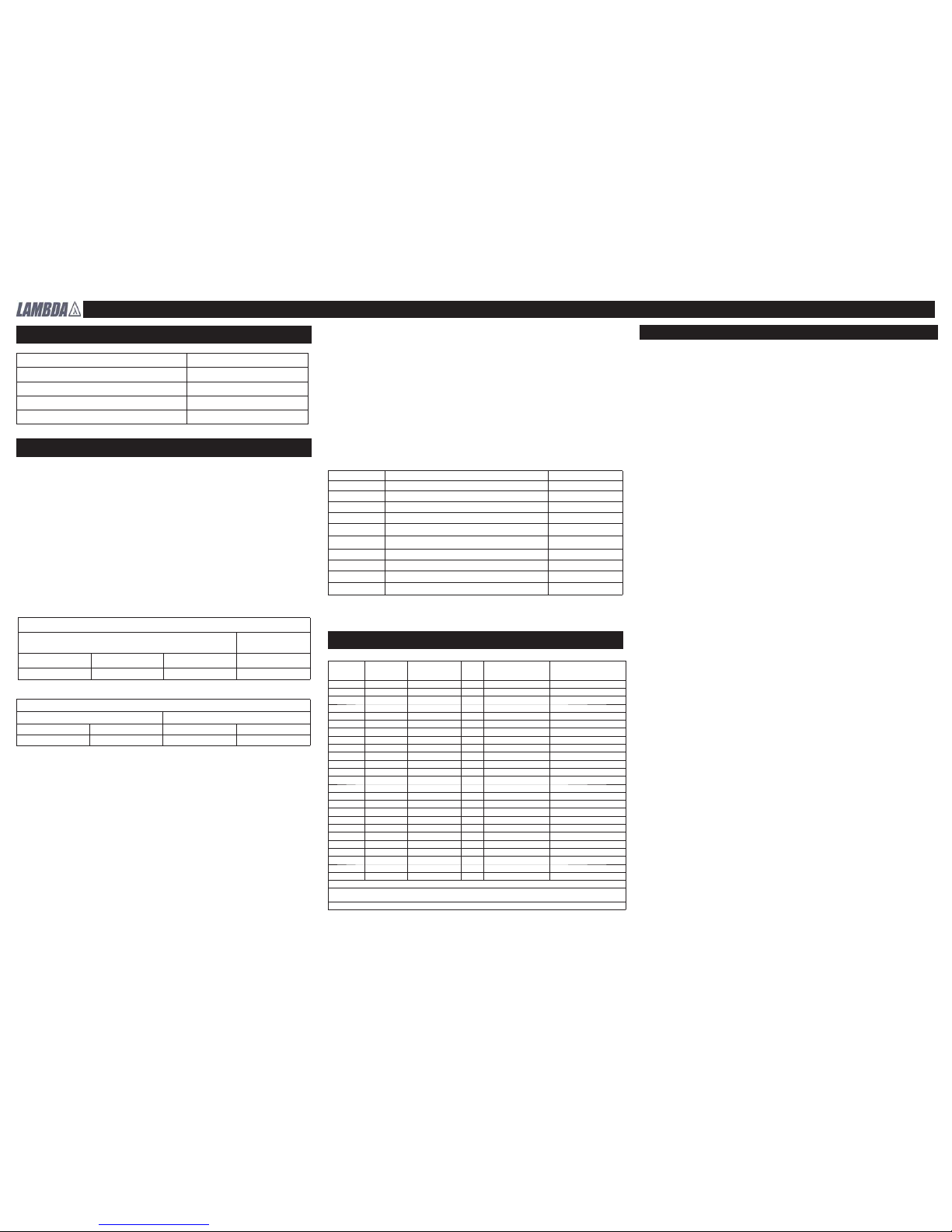
OUTPUTS
Cooling,Output Power and Output Current Limitations
i) Power limitation method.
Integral Fan Cooling (all orientations)
Normal Airfl ow
(air into unit at input end)
Reverse Airfl ow
(air into unit at output
end)
Top Fan with Molex
(TM)
End Fan with Molex
(EM)
End Fan with IEC
(EI & EIF)
End Fan with IEC
(EIR & EIFR)
245W 250W 250W 210W
To determine the component temperatures tests must be conducted in accordance with the requirements of IEC/EN/UL/CSA60950-1, Clause 4.5. Consideration should also be given to the requirements of other safety standards. Note:
Max. temperatures given are as required by EN60950-1 or to provide satisfactory reliability, whichever is the lower.
Test requirements include: PSU to be fi tted in its end-use equipment and operated under the most adverse conditions permitted in the end-use equipment
handbook/specifi cation and which will result in the highest
temperatures in the PSU. To determine the most adverse conditions consideration should be given to the maximum operating ambient, PSU loading and
input voltage, ventilation, equipment orientation, the position of doors & covers,
etc. Temperatures should be monitored using type K fi ne wire thermocouples
(secured with cyanoacrylate adhesive, or similar) placed on the hottest part of
the component and the equipment should be run until all temperatures have
stabilised.
Customers Airfl ow (all orientations) (NM)
Normal Airfl ow (air into unit at input end) Reverse Airfl ow (air into unit at output end)
2.5 m/s 3 m/s 2.5 m/s 3 m/s
220W * 230W 175W 200W
Circuit Ref Description Max Temp (
0
C)
TX1 Power transformer primary, secondary and core 130
TX2 Drive transformer windings 110
L1 & L6 Choke winding 110
L12 Choke winding and core 120
- All other choke windings 115
F1 Input fuse end cap and clip 100
C1 & C18 X capacitors 100
C5 Reservoir electrolytic capacitor 85
- Electrolytic capacitors < 10mm diaameter 90
- Electrolytic capacitors >- 10mm diameter 95
* Output 2, 3.3V, is derated to 15A from 16A.
ii) Temperature Measurement Method:
The following method must be used for determining the safe operation of PSU’s
with the LM option (open frame). It may be used as an alternate method to (i)
above, for determining the safe operation of NM option PSU’s.
For PSU’s cooled by customer supplied airfl ow the components listed in the
table below must not exceed the temperatures given (including when the end
use equipment is operated at its maximum permitted ambient), consequently
the maximum temperature rise permitted is given by the temperatue given in the
table minus the T mra (maximum ambient) of the end use environment (maximum permitted T
mra is 500C). All other ratings given in this handbook remain
unchanged except that the maximum output power is 250W.
Module
Output
Range
Current
Turns
Short Circuit
Current (*3)
Min setting for
Hazardous Energy
(*4)
5/3 base 5.0 - 5.7V 35A(*2) 1T 80A 3V
2.7 - 3.5V 16A 1T 80A -
5/12 base 5.0 - 5.7V 35A(*2) 1T 80A 3V
11 - 16V 8A (12A peak) 4T 20A 5 base 5 - 5.7V 35A(*2) 1T 80A 3V
24 base 23-28V 10A(*2) 4T 20A 12V
A 4.5 - 5.5V 10A 2T 40A B 11 - 15V 8A 4T 20A C 16 - 28V 4A 8T 10A D 4.5 - 5.5V 5A 2T 40A -
2.7 - 3.9V 5A 2T 40A -
E 4.5 - 5.5V 5A 2T 40A -
9 - 15V 4A 4T 20A F 4.5 - 5.5V 5A 2T 40A -
16 - 28V 2A 7T 11.5A G 9 - 15V 4.5A 4T 20A -
9 - 15V 4.5A 4T 20A H 9 - 15V 4A 4T 20A
16 - 28V 2A 7T 11.5A J 16 - 28V 2A 7T 11.5A -
16 - 28V 2A 7T 11.5A L 1.8 - 3.9V 10A 2T 40A M 4.5 - 5.5V 5A 2T 40A -
4.5 - 5.5V 5A 2T 40A N 11 - 14.5V 8A 4T 20A *2 = A minimum load of 10% is required on these outputs.
*3 = Maximum current if output is short circuited, within 1 minute current limit changes to
‘hiccup’ mode to give a lower average current.
*4 = It may not be possible to set the output this low.
Output Ratings
See component layout drawing on page 4
Approval Limitations: Use in North America (AC units only)
When this product is used on 180VAC-250VAC mains with no neutral, connect the two live wires
to L(live) and N (neutral) terminals on the input connector. In this instance double pole fusing is
required.
High Voltage Warning
Dangerous voltages present within the power supply. Do not remove covers.
External Hot Surfaces
Section 6 of the Health and Safety at Work Act requires that manufacturers have an obligation to
protect service engineers as well as users. In order to comply with this, a label must be fi tted to
these products which is clearly visible to service personnel accessing the overall equipment, and
which legibly warns that surfaces of these products may be hot and must not be touched when the
products are in operation.
Safety Earthing Screw
On products with an enclosure, special safety earthing screws are used which connect the cover to
the chassis. They must not be removed.
Safety Class of Protection
These products are designed for the following parameters : Material Group IIIb, Pollution Degree 2,
Overvoltage Category II, Class 1 (earthed), Indoor use as part of an overall equipment such that
the product is accessible to service engineers only.
Energy and Voltage Hazards
Certain modules are capable of providing hazardous energy (240VA) according to output voltage
setting. Final equipment manufacturers must provide protection to service personnel against
inadvertent contact with these module output terminals. If set such that hazardous energy can
occur then the module terminals or connections must not be user accessible.Non-seriesed outputs
that are earthed in the end use equipment are SELV .If outputs are not earthed they must be
considered hazardous, as a single fault in the secondary may make them exceed the SELV limits
between output and earth. If any output is non-SELV then all outputs become non SELV. Outputs
connected in series may produce non-SELV levels, and this must be taken into account in the
end-use application.
Servicing
These products are not customer serviceable. Repairs may only be carried out by Lambda UK or
their authorised agents. These products are not authorised for use as critical components in nuclear
control systems, life support systems or equipment for use in hazardous environments without the
express written approval of the Managing Director of Coutant Lambda Ltd.
Important safety instructions
Page 2
Sirius 250 Handbook Part Number 17132
Input markings and symbols
Mechanical parameters
DO NOT USE MOUNTING SCREWS WHICH PENETRATE THE UNIT BY MORE THAN 4.5 MM.
Weight 2 Kg dependent upon confi guration.
Operation
Temperature 0 to 50
0
C (derating 2.5%0C above 500C to 650C -Not covered by approvals).
Humidity 5 to 95% RH non-condensing. Air Pressure 78kPa to 106kPa.
Altitude -200m to 3000m
Storage and Transportation
Temperature -40
0
C to +850C. Humidity 5% to 95% RH non-condensing.
Air Pressure 54kpa to 106kpa. Altitude -200m to 5000m.
Vibration and shock
10-200Hz @ 1.5G sinewave, 20G for 15 minutes in 3 axes random vibration / 3000 bumps, 10G
(16mS) half sinewave.
Cooling
These units may be mounted in any orientation, unless stated otherwise. The airfl ow around the
power supply air inlets and outlets must not be impeded when it is fi tted in the end use application.
Environmental parameters
Level of insulation
Dielectric Strength testing is carried out as follows:
Primary mains circuit to earth 2.25-2.35 KVDC;
*Primary mains circuits to transformer core 4.25-4.35 KVDC;
*Primary mains circuits to secondary 4.25-4.35 KVDC.
Outputs to each other and to earth are isolated to 100 VDC except:
i) Output 1 and output 2 on the 5/3 and 5/12 base boards.
ii) Outputs of twin D module to each other.
*Important Note: This test is not possible with Y capacitors fi tted to the unit as damage to these
capacitors will occur. It is also necessary to short circuit the outputs together and to earth.
EMC performance
Emissions : EN55022 Conducted RFI-Class A or B (depending on product - Consult Technical
Sales). Radiated RFI - Class A. EN61000-3-2 - Pass - Class A and D. EN61000-3-3 - Pass
Immunity: EN61000-4-2 - Level 4 Criteria B EN61000-4-3 - Level 3 Criteria B
EN61000-4-4 - Level 4 Criteria B EN61000-4-5 - Level 3 Criteria B (installation class 3)
EN61000-4-6 - Level 3 Criteria B
EN61000-4-11 - Pass VDE 0160 - Class 2 (Clause 7.3.1.1.)
General installation instructions
i) The Sirius family of component power supplies is designed for use within other equipment or
enclosures which restrict access to authorised competent personnel only. For safe installation and
operation of this product, carefully follow the instructions below.
ii) The unit cover/chassis is designed to protect skilled personnel from hazards. They must not be
used as part of the external covers of any equipment where they may be accessible to operators,
since under full load conditions, part or parts of the unit chassis may reach temperatures in excess
of those considered safe for operator access. On units with end fans and IEC 60320 connector, the
fan and connector end of the unit is permitted to be user accessible, this also applies to the top fan
on units where this is fi tted.
Enclosures made with punched ventilation grilles are not to be user accessible.
iii) The mains switch, where fi tted, is a single pole device and must not be used as the main disconnect device. The IEC 60320 mains appliance coupler is intended to be the main disconnect device
for the Sirius power supply. The switch is marked ‘I’ and ‘O’. The ‘I’ indicates on and ‘O’ indicates
off.
CAUTION: Where the IEC 60320 is fused, then it is double-pole/neutral fused. When the fused IEC
inlet is fi tted, the IEC input must not be user or externally accessible in the end use equipment.
iv) These products are Class 1 and must therefore be reliably earthed and professionally installed in
accordance with the prevailing electrical wiring regulations and the safety standards covered herein.
v) These products are IPX0 and chemicals/solvents, cleaning agents and other liquids must not be
used.
These products carry the following approvals:
UL60950-1 and CSA22.2 No 60950-1 - UL Recognised. C-UL for Canada.
IEC/EN60950-1 - CE mark.
CE marking when applied to any Sirius product, indicates compliance with the Low Voltage Directive (2006/95/EC) In that it complies with EN60950-1.
Safety approvals
alternating current (a.c.).
direct current (d.c.).
danger, shock hazard.
caution, refer to supplementary documents.
Customer Signals
Inhibit (Pin1)
Connecting Pin1 (Inhibit) to Pin5 (Ch1 –ve sense) via open-collector driver or relay/switch contact
shuts off all DC outputs (cooling fan continues to operate).
Pin1 is internally pulled high via 2K2 resistor to approximately 5Volts with respect to Pin5.
AC Fail (Pin2)
Pin2 (AC Fail) is an open-collector output referenced to Pin5 (Ch1 –ve sense) that is normally low
and goes high at least 5mS before DC outputs are lost.
Maximum sink current is 50mA, maximum external open circuit voltage is 45V.
Ch1 / Ch2 sense (Pins3,4,5,6)
Connecting sense terminals to the load will compensate for power cable voltage drop under load
conditions. With sense terminals connected, the voltage drop along any power cable should not be
allowed to exceed 0.5volts.
The sense terminals can be left unconnected if remote sense is not required (sense terminals are
internally connected via a 10 ohm resistor to the corresponding power terminal).
Sense cables should be connected as twisted pairs (+ve and –ve sense) with at least 1 twist
per centimetre and sense cable harness should be kept separate from the power cable harness
wherever possible.
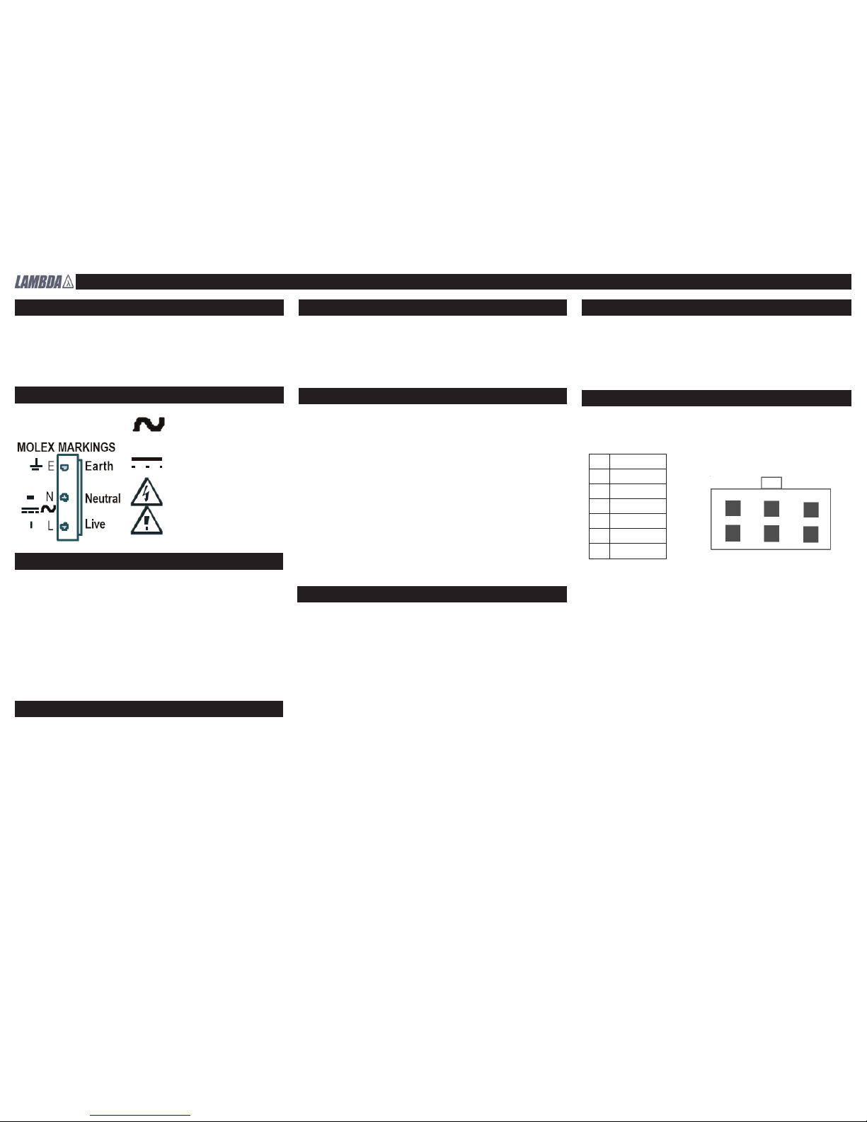
Customer signals are available via 6-way connector (PCB reference J9) adjacent to output 1
terminals. A connector kit (Molex housing 90142 and Molex crimp pins 90119-2109) is supplied
with each PSU. Pin designations for this connector are as follows :
Connection details
Input Connections
Input tabs - 6.3mm x 0.8mm, tin plated brass, rated 15A.
Internal fuse (F1) 5 x 20mm, F6.3AH/250V.
Output Connections
Output Connector Ratings: 6.35mm fastons are rated at 15A.
PIN FUNCTION
1 Inhibit
2 A/C Fail
3 Ch2 -ve sense
4 Ch2 +ve sense
5 Ch1 -ve sense
6 Ch1 +ve sense
1
3
2
4
5
6
Maximum screw torque for customer fi xings 0.9Nm
Page 3

Sirius 250 Handbook Part Number 17132
Sirius 250 Outline Drawing - Top Mounted Fan
Sirius 250 Outline Drawing - End Mounted Fan
Sirius 250 Outline Drawing - No Fan
Page 4

Sirius 250 Handbook Part Number 17132
CEL Part No. 17132 Issue 19, October 2007
Coutant Lambda Limited,
Kingsley Avenue, Ilfracombe, Devon, EX34 8ES.
Telephone - Sales and Service (01271) 856666.
Head Offi ce and Works (01271) 856600. Facsimile (01271) 864894.
WEBSITE: www.lambda-gb.com
Component Layout Drawing
 Loading...