

Page 1

USER MANUAL
OPTex
07/2005
LP Part Number: 263 292
Document Code: A0507OPTex
Page 2

U.S.A.
Lambda Physik USA, Inc.
3201 West Commerical Blvd.
Ft. Lauderdale, FL 33309, USA
Tel.: +1 (954) 486-1500
1 (800) EXCIMER
Fax: +1 (954) 486-1501
eMail: marketingusa@lambdaphysik.com
Internet: http://www.lambdaphysik.com/optex
JAPAN
Lambda Physik Japan Co., Ltd.
German Industry Center
1-18-2 Hakusan, Midori-ku
Yokohama 226-0006, Japan
Tel.: +81 (45) 939-7848
Fax: +81 (45) 939-7849
GERMANY
Lambda Physik AG
Hans-Böckler-Strasse 12
D - 37079 Göttingen, Germany
Tel.: +49 (551) 6938-0
Fax: +49 (551) 68691
eMail: salesgermany@lambdaphysik.com
Marubun Corp.
Marubun Daiya Bldg.
8-1 Nihonbashi Odenmacho
Chuo-ku, Tokyo 103-8577, Japan
Tel.: +81 (3) 3639-9811
Fax: +81 (3) 3662-1349
Page 3

CONTENTS
1 INTRODUCTION
2 LASER DEVICE FUNDAMENTALS
3SAFETY
4 SPECIFICATIONS AND REQUIREMENTS
5 INSTALLATION
6 LASER CONTROL
7OPERATION
8 MAINTENANCE
9 TROUBLESHOOTING
10 DIAGRAM SCHEMATICS
LIST OF FIGURES
INDEX
Page 4

Page 5

TABLE OF CONTENTS
1 INTRODUCTION . . . . . . . . . . . . . . . . . . . . . . 1
1.1 About this Manual . . . . . . . . . . . . . . . . . . . . . . . . . . 1
1.1.1 Purpose, Availability and Use. . . . . . . . . . . . . . . . 1
1.1.2 Intended Audience . . . . . . . . . . . . . . . . . . . . . . . . 2
1.1.3 Numbering of Chapters, Pages and Instructions . 2
1.2 Safety . . . . . . . . . . . . . . . . . . . . . . . . . . . . . . . . . . . . 3
1.2.1 Laser Safety Classification. . . . . . . . . . . . . . . . . . 3
1.2.2 Safety Information . . . . . . . . . . . . . . . . . . . . . . . . 3
1.2.3 Signal Words and Symbols in this Manual. . . . . . 3
1.3 Overview of Chapters . . . . . . . . . . . . . . . . . . . . . . . 5
1.4 Conversion Tables . . . . . . . . . . . . . . . . . . . . . . . . . 6
1.4.1 Measurements . . . . . . . . . . . . . . . . . . . . . . . . . . . 6
1.4.2 Temperatures. . . . . . . . . . . . . . . . . . . . . . . . . . . . 6
A0507OPTex
1.5 Patents and Trademarks. . . . . . . . . . . . . . . . . . . . . 7
1.5.1 Patents . . . . . . . . . . . . . . . . . . . . . . . . . . . . . . . . . 7
1.5.2 Trademarks . . . . . . . . . . . . . . . . . . . . . . . . . . . . . 9
1.6 Feedback Regarding Documentation . . . . . . . . . 10
2 LASER DEVICE FUNDAMENTALS . . . . . . 11
2.1 Excimer Laser . . . . . . . . . . . . . . . . . . . . . . . . . . . . 11
2.1.1 The NovaTube
2.2 Laser Terminology According to ISO 11145. . . . 12
2.3 Fundamental Design of the OPTex . . . . . . . . . . . 13
2.4 Overview of the OPTex . . . . . . . . . . . . . . . . . . . . . 14
2.5 Laser Control. . . . . . . . . . . . . . . . . . . . . . . . . . . . . 17
2.6 Laser Tube . . . . . . . . . . . . . . . . . . . . . . . . . . . . . . . 18
2.7 Thyratron . . . . . . . . . . . . . . . . . . . . . . . . . . . . . . . . 20
2.8 Energy Monitor . . . . . . . . . . . . . . . . . . . . . . . . . . . 21
2.9 Operating Modes. . . . . . . . . . . . . . . . . . . . . . . . . . 21
®
Innovation . . . . . . . . . . . . . . . . 11
LAMBDA PHYSIK - 07/2005 CONTENTS - I
Page 6

TABLE OF CONTENTS
2.10 Safety Systems of the OPTex. . . . . . . . . . . . . . . . 23
2.10.1 Safety Interlock. . . . . . . . . . . . . . . . . . . . . . . . . . 24
2.10.2 Electronics Chamber . . . . . . . . . . . . . . . . . . . . . 24
2.10.3 Tube Chamber . . . . . . . . . . . . . . . . . . . . . . . . . . 24
3 SAFETY . . . . . . . . . . . . . . . . . . . . . . . . . . . . 25
3.1 General Safety Aspects . . . . . . . . . . . . . . . . . . . . 25
3.1.1 Basic Operation and Designated Use . . . . . . . . 25
3.1.2 Organizational Measures . . . . . . . . . . . . . . . . . . 26
3.1.3 Selection and Qualification of Personnel
- Basic Responsibilities . . . . . . . . . . . . . . . . . . . 27
3.1.4 Safety Instructions Governing
Specific Operational Phases . . . . . . . . . . . . . . . 28
3.2 Specific Safety Aspects . . . . . . . . . . . . . . . . . . . . 30
3.2.1 Physical Hazards . . . . . . . . . . . . . . . . . . . . . . . . 31
3.2.2 Personnel Safety . . . . . . . . . . . . . . . . . . . . . . . . 35
3.2.3 Constructive Safety Features. . . . . . . . . . . . . . . 42
3.3 Safety Compliance List. . . . . . . . . . . . . . . . . . . . . 46
3.4 Labels. . . . . . . . . . . . . . . . . . . . . . . . . . . . . . . . . . . 47
3.4.1 Label Location Diagrams . . . . . . . . . . . . . . . . . . 48
3.4.2 Description of the Labels and Safety Labels . . . 50
4 SPECIFICATIONS AND REQUIREMENTS. 51
4.1 Specifications . . . . . . . . . . . . . . . . . . . . . . . . . . . . 51
4.2 Physical Dimensions . . . . . . . . . . . . . . . . . . . . . . 52
4.3 Electrical Power Supply . . . . . . . . . . . . . . . . . . . . 54
4.4 Remote Control Interlock . . . . . . . . . . . . . . . . . . . 55
4.5 Controller Requirements . . . . . . . . . . . . . . . . . . . 56
4.6 External Trigger In and Pre-Trigger Out . . . . . . . 57
4.6.1 TWE Trigger Converter (Option) . . . . . . . . . . . . 57
CONTENTS - II User Manual OPTex
Page 7

TABLE OF CONTENTS
4.7 Gas Requirements. . . . . . . . . . . . . . . . . . . . . . . . . 59
4.7.1 Gas Lines . . . . . . . . . . . . . . . . . . . . . . . . . . . . . . 60
4.7.2 Pressure Regulators. . . . . . . . . . . . . . . . . . . . . . 60
4.7.3 Gas Cabinets . . . . . . . . . . . . . . . . . . . . . . . . . . . 60
4.7.4 Gases Required (Premix). . . . . . . . . . . . . . . . . . 61
4.7.5 Optimum Gas Mixtures (Single Gases) . . . . . . . 62
4.8 Air Intake and Exhaust . . . . . . . . . . . . . . . . . . . . . 63
4.9 Environmental Conditions . . . . . . . . . . . . . . . . . . 64
4.10 Space Requirements. . . . . . . . . . . . . . . . . . . . . . . 64
5 INSTALLATION . . . . . . . . . . . . . . . . . . . . . . 65
5.1 Site Preparation. . . . . . . . . . . . . . . . . . . . . . . . . . . 65
5.2 Transport Locks . . . . . . . . . . . . . . . . . . . . . . . . . . 66
5.3 Insert Safety Plug . . . . . . . . . . . . . . . . . . . . . . . . . 66
5.4 Connect Controller . . . . . . . . . . . . . . . . . . . . . . . . 67
5.4.1 Connecting the PC (PC-Powered Convertor). . . 67
5.4.2 Connecting the PC (Mains-Powered Convertor) 69
5.5 Software Installation . . . . . . . . . . . . . . . . . . . . . . . 70
5.6 Connect External Trigger . . . . . . . . . . . . . . . . . . . 71
5.7 Connect Power Supply Line. . . . . . . . . . . . . . . . . 72
5.8 Connect Exhaust Line (Option) . . . . . . . . . . . . . . 73
5.9 Gas Lines Installation . . . . . . . . . . . . . . . . . . . . . . 74
5.9.1 Remarks Regarding Gas Line Installation . . . . . 74
5.9.2 Connect Gas Supply Lines. . . . . . . . . . . . . . . . . 75
5.10 Connect Beam Guidance System
(for F
5.11 New Gas Fill. . . . . . . . . . . . . . . . . . . . . . . . . . . . . . 78
Version) . . . . . . . . . . . . . . . . . . . . . . . . . . . 77
2
6 LASER CONTROL. . . . . . . . . . . . . . . . . . . . 79
A0507OPTex
LAMBDA PHYSIK - 07/2005 CONTENTS - III
6.1 Laser Control Software. . . . . . . . . . . . . . . . . . . . . 79
6.1.1 Start Laser Control Software . . . . . . . . . . . . . . . 79
6.1.2 Exit Laser Control Software . . . . . . . . . . . . . . . . 80
6.1.3 Laser Control Screen . . . . . . . . . . . . . . . . . . . . . 80
6.2 Service Software . . . . . . . . . . . . . . . . . . . . . . . . . . 88
6.3 Logbook file. . . . . . . . . . . . . . . . . . . . . . . . . . . . . . 88
Page 8

TABLE OF CONTENTS
7 OPERATION . . . . . . . . . . . . . . . . . . . . . . . . 89
7.1 Check Beam Path . . . . . . . . . . . . . . . . . . . . . . . . . 89
7.2 Start-Up Laser Device. . . . . . . . . . . . . . . . . . . . . . 90
7.2.1 Turn On Gas Supply. . . . . . . . . . . . . . . . . . . . . . 90
7.2.2 Switch On Laser Device and Controller . . . . . . . 92
7.3 Methods of Operation . . . . . . . . . . . . . . . . . . . . . . 95
7.3.1 Laser Operation Modes . . . . . . . . . . . . . . . . . . . 96
7.3.2 Gas Modes. . . . . . . . . . . . . . . . . . . . . . . . . . . . 100
7.4 Start and Stop Laser Operation . . . . . . . . . . . . . 101
7.4.1 Start Laser Operation. . . . . . . . . . . . . . . . . . . . 101
7.4.2 Stop Laser Operation . . . . . . . . . . . . . . . . . . . . 103
7.5 Shut-Down Laser Device . . . . . . . . . . . . . . . . . . 103
7.5.1 Switch Off Laser Device and Controller . . . . . . 103
7.5.2 Turn Off Laser Gases. . . . . . . . . . . . . . . . . . . . 104
8 MAINTENANCE. . . . . . . . . . . . . . . . . . . . . 107
8.1 Laser Logbook. . . . . . . . . . . . . . . . . . . . . . . . . . . 108
8.2 Laser Device Design . . . . . . . . . . . . . . . . . . . . . . 108
8.3 Maintenance Schedule . . . . . . . . . . . . . . . . . . . . 109
8.4 Gas Line Maintenance . . . . . . . . . . . . . . . . . . . . 110
8.4.1 Flush Premix Gas Line (External Flushing) . . . 110
8.4.2 Exchange Premix Gas Cylinder . . . . . . . . . . . . 112
8.4.3 Exchange Inert Gas Cylinder . . . . . . . . . . . . . . 114
8.5 New Gas Fill. . . . . . . . . . . . . . . . . . . . . . . . . . . . . 116
8.6 Windows Maintenance . . . . . . . . . . . . . . . . . . . . 118
8.6.1 Windows Exchange . . . . . . . . . . . . . . . . . . . . . 119
8.6.2 Windows Alignment . . . . . . . . . . . . . . . . . . . . . 127
8.6.3 Disassembling / Assembling Window Mounts . 132
8.6.4 Windows Cleaning . . . . . . . . . . . . . . . . . . . . . . 136
8.7 Halogen Filter Maintenance . . . . . . . . . . . . . . . . 140
8.7.1 Halogen Filter Exchange . . . . . . . . . . . . . . . . . 140
8.7.2 Halogen Filter Disposal . . . . . . . . . . . . . . . . . . 142
8.8 Energy Monitor Calibration . . . . . . . . . . . . . . . . 143
CONTENTS - IV User Manual OPTex
Page 9

TABLE OF CONTENTS
9 TROUBLESHOOTING. . . . . . . . . . . . . . . . 147
9.1 Fuses . . . . . . . . . . . . . . . . . . . . . . . . . . . . . . . . . . 148
9.2 Possible Problems and Solutions . . . . . . . . . . . 149
9.2.1 Power-Up Error . . . . . . . . . . . . . . . . . . . . . . . . 149
9.2.2 Statical Errors. . . . . . . . . . . . . . . . . . . . . . . . . . 150
9.2.3 Operation Errors. . . . . . . . . . . . . . . . . . . . . . . . 152
10 DIAGRAM SCHEMATICS . . . . . . . . . . . . . 155
10.1 Gas Flow Diagram . . . . . . . . . . . . . . . . . . . . . . . . 155
10.2 Electrics Diagram . . . . . . . . . . . . . . . . . . . . . . . . 156
10.3 Fiber Optic Light Waveguide Diagram . . . . . . . 157
10.4 Safety Circuits Diagram . . . . . . . . . . . . . . . . . . . 158
LIST OF FIGURES. . . . . . . . . . . . . . . . . . . 159
INDEX. . . . . . . . . . . . . . . . . . . . . . . . . . . . . 161
A0507OPTex
LAMBDA PHYSIK - 07/2005 CONTENTS - V
Page 10

TABLE OF CONTENTS
CONTENTS - VI User Manual OPTex
Page 11

1 INTRODUCTION
This chapter outlines:
– the purpose as well as the necessary availability and use of the
instruction manual,
– the persons, for whom the instruction manual is intended,
– how the instruction manual is organized,
– the use of signal words and safety signs in the instruction manual,
– the contents of each chapter.
1.1 About this Manual
About this Manual
1.1.1 Purpose, Availability and Use
This instruction manual is intended to familiarize the user with the
OPTex and its designated use.
The instruction manual contains important information to installing and
operate the OPTex safely, properly and most efficiently. Observing
these instructions helps to avoid danger, reduce repair costs and
downtimes and increase the reliability and lifetime of the OPTex.
The instruction manual must always be available wherever the OPTex
is in use.
The instruction manual must be read and applied by any person in
charge of carrying out work with and on the OPTex, e.g.:
– operation including setting up, troubleshooting in the course of work,
removal of production waste, care and disposal of consumables.
– maintenance (servicing, inspection, repair) and/or
– transport.
The instruction manual is to be supplemented by the respective
national rules and regulations for accident prevention and
environmental protection.
A0507OPTex
LAMBDA PHYSIK - 07/2005 1
Page 12

INTRODUCTION
1.1.2 Intended Audience
This manual is intended for:
– Operators, who have completed the OPTex Basic Operations
course. An operator operates the OPTex excimer laser in normal
day-to-day operations.
– Process engineers, who have completed the OPTex Advanced
Operations course. A process engineer prepares jobs for production
and other purposes and monitors production quantity and quality.
– Any reader who wishes to acquire general knowledge of the OPTex
excimer laser.
1.1.3 Numbering of Chapters, Pages and Instructions
The pages of this manual are numbered continuously. The page
number appears in the lower outside corner of every page.
The chapters are numbered continu o us ly. Th e na m e of the ch ap te r
appears in the upper outside corner of every even page, the name of
the main section appears in the upper outside corner of the
corresponding odd page.
Each chapter ends with an even page number. Consequently, certain
even pages at the ends of chapters will be intentionally left blank.
Each step within a procedure is sequentially numbered.
2 User Manual OPTex
Page 13

1.2 Safety
1.2.1 Laser Safety Classification
Lasers and laser systems are classified according to their relative
hazards. These classifications are found in the American National
Standards for the Safe Use of Lasers (ANSI Z 136.1-1986),
FDA 21 CFR 1040.10 and 1040.11 and IEC-825.
Within this classification, the OPTex excimer laser is a class IV
(high power) laser. It must be regarded as a potential hazard to
the human operator. When connected to a correspondingly
configured beam guidance system, the OPTex becomes a class I laser
device.
The laser beam must also be regarded as a potential fire hazard.
1.2.2 Safety Information
Safety
Chapter 3 (Safety) describes the physical hazards related to the laser
device, the means of protection against these hazards and the safety
features incorporated in the design of the laser device.
The Safety Chapter must be read by all persons entrusted with any
sort of work on the OPTex excimer laser device.
Never start to follow the procedures detailed in this manual
unless you have read and fully understood the information given
in the Safety Chapter.
1.2.3 Signal Words and Symbols in this Manual
Contained within this manual are sections in which particular hazards
are defined or special attention is drawn to particular conditions. These
are indicated with signal words in accordance with ANSI Z-535.2 -1991
and safety symbols (pictorial hazard alerts) in accordance with ANSI
Z535.3-1991. The signal words are de fined in section 1.2.3.1 of this
manual and the safety symbols in section 1.2.3 .2 .
1.2.3.1 Signal Words
A0507OPTex
LAMBDA PHYSIK - 07/2005 3
Four signal words are used in this manual: DANGER, WARNING,
CAUTION and NOTE. The signal words DANGER, WARNING and
CAUTION designate the degree or level of hazard:
DANGER
Indicates an imminently
avoided, will result in death or serious injury
hazardous situation which, if not
.
Page 14
INTRODUCTION
WARNING
Indicates a potentially
avoided, could result in death or serious injury
CAUTION
Indicates a potentially
may result in minor or moderate injury
against unsafe practices that may result in property damage.
Use of the signal word ”NOTE”:
NOTE
Used to define sections, where particular attention should be paid
to ensure efficient operation or servicing of the laser device.
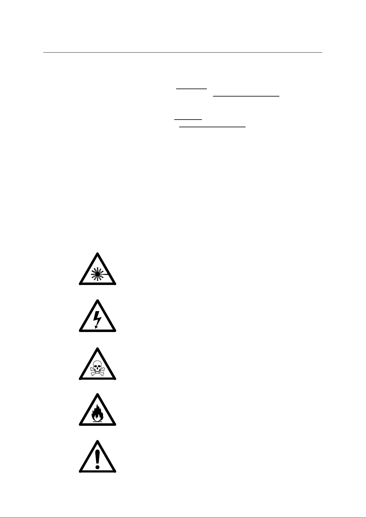
1.2.3.2 Symbols
The signal words DANGER, WARNING, and CAUTION are always
emphasized with a safety symbol. These safety symbols are used to
indicate special hazards. They are used regardle ss of the hazard level:
hazardous situation which, if not
.
hazardous situation which, if not avoided,
. It is also used to alert
This symbol is combined with one of the signal words DANGER,
WARNING or CAUTION to indicate a hazardous situation caused by
laser radiation.
This symbol is combined with one of the signal words DANGER,
WARNING or CAUTION to indicate a hazardous situation caused by
electricity.
This symbol is combined with one of the signal words DANGER,
WARNING or CAUTION to indicate a hazardous situation caused by
toxic substances.
This symbol is combined with one of the signal words DANGER,
WARNING or CAUTION to indicate a hazardous situation caused by
flammable substances.
This symbol is combined with one of the signal words DANGER,
WARNING or CAUTION to indicate a hazardous situation caused by
circumstances other than those described above.
4 User Manual OPTex
Page 15

1.3 Overview of Chapters
Chapter 1 (this chapter).
•
Chapter 2 provides the reader with a short overview of system
•
elements and a description of different subsystems. It introduces
fundamental operational concepts, such as running modes, as well
as familiarizing the reader with organization and function of the
system.
Chapter 3 explains safety and provides an overview of safety signs
•
and identification labels. Described are the main physical hazards as
well as personal and constructional precautions. It is essential that
you read this chapter before performing any t ask on the OPTex.
Chapter 4 describes the specifications, installation requirements,
•
conditions of transport and operation and the accesso ries delivered
with the OPTex.
Chapter 5 describes the installation of the OPTex.
•
Chapter 6 describes the laser control and service software and its
•
application in the operation of the OPTex.
Overview of Chapters
Chapter 7 contains instructions on how to start and operate the
•
OPTex.
Chapter 8 describes fundamental maintenance routines, which can
•
be performed by instructed operators.
Chapter 9 explains what action the operator can take when errors
•
occur and how to trace errors.
Chapter 10 gives an overview of wiring diagrams and schematics.
•
The last pages of this manual include a list of figures and a index.
•
A0507OPTex
LAMBDA PHYSIK - 07/2005 5
Page 16

INTRODUCTION
1.4 Conversion Tables
1.4.1 Measurements
Listed below are the units of measure used in this manual and their
equivalents according to the SI standard:
1 meter (m) = 39.37 inches (in)
1 meter (m) = 3.28 feet (ft)
1 centimeter (cm) = 0.3937 inch (in)
1 square meter (m²) = 1,550 square inches (in²)
1 square meter (m²) = 10.76 square feet (ft²)
1 cubic meter (m³) = 35.31 cubic feet (ft³)
1 liter (l) = 0.264 US gallons (gal)
1 kilogram (kg) = 2.20 US pounds (lbs)
1 bar = 100,000 Pascal (Pa)
100,000 Pascal (Pa) = 14.50 pounds force
per square inch (lbf/in²)
1.4.2 Temperatures
The temperatures in this manual are primarily indicated in degrees
celsius (° C).
To convert °C to °F; multiply by 9, divide by 5 and add 32.
To convert °F to °C; subtract 32, multiply by 5, divide by 9.
As a guide, we have converted below some temperature values from
°C to °F:
-10 °C = 14 °F
0 °C = 32 °F
5 °C = 41 °F
16 °C = 61 °F
20 °C = 68 °F
38 °C = 100 °F
100 °C = 212 °F
6 User Manual OPTex
Page 17

1.5 Patents and Trademarks
1.5.1 Patents
Lambda Physik GmbH is owner of the following patents:
Germany: P 32 12 928.9 “Entladungsgepumpter Laser”
US Patent # 4,534,034 “Discharge-pumped laser”
Germany: P 33 35 690.4 “Vorrichtung zum Erzeugen von
Hochleistungs-Hochspannungsimpulsen
hoher Wiederholfrequenz”
Germany: P 38 17145.7 “Elektrode für gepulste Gaslaser und ihre
Verwendung”
Germany: G 88 17 197.3 “Elektrode für gepulste Gaslaser”
US Patent # 4,860,300 “Electrode for pulsed gas lasers”
Patents and Trademarks
Germany: P 37 14 503.7 “Steuerschaltung für einen gepulsten
Gaslaser und Verfahren zum
Initialisieren der Steuerschaltung”
US Patent #4,916,707 “Control circuit for a pulsed gas laser”
US Patent # 4,993,042 “Device for mounting a window on a gas
discharge laser”
US Patent # 4,980,894 “Ignitor for the preionization of a gas
discharge laser”
US Patent # 4,951,295 “Preionization means for a gas discharge
laser”
Germany: G 8906 627.8 “Vorrichtung zum Reinigen von
Lasergas”
Germany: P 40 03 841.6-09 “Laserresonator”
US Patent #5,220,574 “Excimer laser with hydrogen chloride
and method for producing hydrogen
chloride for an excimer laser”
Japan 1 991 984 “Excimer laser with hydrogen chloride
and method for producing hydrogen
chloride for an excimer laser”
Germany: P 42 06 803.7-09 “Verfahren zum Nachfüllen von
Halogengas in das Gasreservoir eines
Excimerlasers”
A0507OPTex
LAMBDA PHYSIK - 07/2005 7
US Patent # 5,396,514 “Excimer laser comprising a gas
reservoir and a collecting receptacle and
a method of refilling the gas reservoir of
the laser”
Germany: G 92 08 936.4 “Laserresonator”
Page 18

INTRODUCTION
Germany: P 42 33 634.1 “Elektroden für die Entladungseinheit
eines Excimerlasers”
US Patent # 5,347,532 “Laser having at least one anode and one
cathode for preionization and/or
discharge”
Japan: Hei 5-262 989/93 “Laser having at least one anode and one
cathode for preionization and/or
discharge”
US Patent # 4,977,573 “Excimer laser output control device”
US Patent # 4,611,270 “Method and means of controlling the
output of a pulsed laser”
Germany: P 43 35 079.8-33 “Elektroden in einer Fluor enthaltenden
Entladungseinheit eines gepulsten
Gasentladungslasers”
Germany: G 93 20 768.9 “Elektroden in einer Fluor enthaltenden
Entladungseinheit eines gepulsten
Gasentladungslasers”
Germany: G 94 01 808.1 “Vorrichtung zum Regeln der Temperatu r
von Lasergas, insbesondere eines
Excimerlasers”
Germany: 295 20 820.1 “Laserröhre für halogenhaltige
Gasentladungslaser”
US Patent # 4,611,327 “Gas transport laser system”
US Patent # 4,549,091 “Electrical excitation circuit for gas laser”
US Patent # 4,393,505 “Gas discharge laser having a buffer gas
of neon”
US Patent # 4,340,968 “Rare gas hydrogen-halide excimer laser
with hydrogen additive”
Germany P 44 00 345.5 “Vorrichtung für die Reinigung von
Lasergas”
8 User Manual OPTex
Page 19

1.5.2 Trademarks
LAMBDA PHYSIK is a registered trademark of Lambda
OPTex is a trademark of Lambda Physik AG
NovaTube is a registered trademark of Lambda
Gyrolok is a registered trademark of Hoke Inc.,
Patents and Trademarks
Physik AG
the Lambda Physik logo is a registered
trademark of Lambda Physik AG
Physik AG
NJ, USA
Microsoft, MS,
Windows, Windows 95 and
Windows NT
IBM is a registered trademark of
are registered trademarks of Microsoft
Corporation in USA and other countries
International Business Machines, Inc.
A0507OPTex
LAMBDA PHYSIK - 07/2005 9
Page 20

INTRODUCTION
1.6 Feedback Regarding Documentation
If you have any comments regarding the documentation provided to
you, please contact us.
When you contact us, please provide us with
– The document code
– The date of issue
– The page number, section number and, where applicable, the
procedure step number
– A description of any errors
– A proposal for improvements
Feedback Address
E-mail documentation@lambdaphysik.com
Post Lambda Physik AG
Documentation Comments
Hans-Böckler-Straße 12
D-37079 Göttingen
Germany
Telefax +49 551 68691
10 User Manual OPTex
Page 21

2 LASER DEVICE
FUNDAMENTALS
This chapter briefly describes the most important features, functions,
and subassemblies of a Lambda Physik excimer laser. This
background information will ease your understanding of the
information contained in the subsequent chapters.
The information in this chapter does not enable you to operate or
service the OPTex excimer laser.
Never switch on or attempt to operate or service the OPTex
before reading, understanding and fully familiarizing yourself
with Chapter 3 of this manual (Safety)!
Excimer Laser
2.1 Excimer Laser
Excimer lasers take their name from the exci ted state dimers from
which lasing occurs. The most important excimers are rare gas halides
such as Argon Fluoride (ArF), Krypton Fluoride (KrF), Xenon Chloride
(XeCl) and Xenon Fluoride (XeF). These produce intense UV light
(U ltra V iolet) on distinct spectral lines between 157nm and 351nm.
2.1.1 The NovaTube
All Lambda Physik excimer lasers use the NovaTube® technology.
The NovaTube
of corrosion and contamination. To ensure strict adherence to these
design objectives, all laser tube components are assembled in a
clean-room. Optimized electrode materials combined with an improved
preionization scheme minimizes electrode erosion. The se major
improvements in laser tube technology lead to an increased laser tube
lifetime.
®
Innovation
®
has been conceived to virtually eliminate the effects
A0507OPTex
LAMBDA PHYSIK - 07/2005 11
Page 22

LASER DEVICE FUNDAMENTALS
2.2 Laser Terminology According to ISO 11145
ISO 11145 (“Optics and Optical Instruments - Lasers and Laser
Related Equipment - Vocabulary and Symbols”) contains a list of laser
terminology.
To prevent misunderstandings, this manual strictly differentiates
between “laser” and “laser device” (see Figure 1). Thus “Start laser
device” means that the power is off and shall be turne d on. To “sta r t
the laser” means to switch on the laser beam and start lasing.
Laser Unit
Laser Device
Supply Units
Power, Cooling, ...
Figure 1: Laser components according to ISO 11145
Laser Assembly
Laser
Mirrors, Lenses, ...
Measuring and
Control Unit
Telescope,
Focussing, ...
Handling Systems
Robotics, Workpiece
Positioning
Definitions:
Laser Lasers consist of an amplifying
medium capable of emitting coherent
radiation with wavelengths up to 1 mm
by means of stimulated emission.
Workpiece
Laser Device A laser, where the radiation is
generated, together with essential
additional facilities (e.g. cooling,
power and gas supply) that are
necessary to operate the laser.
Laser Assembly Laser device together with specific,
normally optical, mechanical and/or
electrical system components for
beam handling and forming.
Laser Unit One ore more laser assemblies
together with handling, measurement
and control systems.
12 User Manual OPTex
Page 23

Fundamental Design of the OPTex
2.3 Fundamental Design of the OPTex
The OPTex is provided with all required power supply and control
units. One-phase mains power supply with protective earth as well as
Premix and Inert gas supply are sufficient for safely and ease
operation. Only a few modules are to be checked and serviced within
determined periods. The maintenance schedule is shown in Section
8.3 on page 109.
The OPTex is the most compact Lambda Physik excimer laser device.
To ensure fail-safe operation and ease-of-service, the laser device
housing is divided into two separate chambers containing the internal
components; designated as the tube chamber and the electronics
chamber.
l
e
n
a
p
k
c
a
B
Tiltable by 90° as
indicated. Feet to be
relocated in recesses
on back panel.
Tube chamber
Electronics chamber
Figure 2: Fundamental design of the OPTex
To enable space at the installation site to be optimally utilized, the
laser device can be installed on its back or on its bottom panel:
recesses for the feet are provided in both pa ne ls.
The installation position (upright or flat) and th e be am exit side are set
at the factory. In this manual, we assume that the laser device is to be
installed on its bottom panel (upright position). The beam is to exit
from the aperture on the right-hand side (shown in Figure 2 and in
Figure 3 on page 14). The gas and power con n ec tion s ar e situ ated on
the left-hand side (see Figure 4 on page 15).
A0507OPTex
LAMBDA PHYSIK - 07/2005 13
Page 24

LASER DEVICE FUNDAMENTALS
O P
T e
x
2.4 Overview of the OPTex
A B
RS232
INTERLOCK
KLM
Figure 3: Right side and front of the OPTex
H
C
Key to Figure 3:
D
E
O PTex
FGI
A Exhaust electronics chamber
B Beam exit aperture (for F
connector)
C Recesses for feet (alternative)
D Key switch
E Front service panel
F Height adjustable feet
G Right-han d se rvic e pa ne l
H Gas connection valve, Inert (alternative)
I Gas connection valve, Premix (alternative)
K Trigger in / Pre trigger out connector (alternative)
L Optical RS232 connector (alternative)
M Interlock connector (alternative)
version with beam guidance system
2
14 User Manual OPTex
Page 25

Overview of the OPTex
A B
INERTPREMIX
NP
O
M
C
POWERON
FUSE2x6.3 WLASEREMISSION
RS232 INTERLOCK
L
EF
D
INDICATOR
IK
Figure 4: Left side and top of the OPTex
G
H
A0507OPTex
Key to Figure 4:
A Exhaust tube chamber
B Air intake tube chamber
C Key switch
D Power ON light
E Air intake electronics chamber
F Laser tube
G Top service panel
H Laser radiation warning lamp
I Interlock connector
K Optical RS232 connector
L Trigger in / Pre trigger out connector
M Mains socket with main fuses
N Left-hand service panel
O Gas connection valve, Inert
P Gas connection valve, Premix
LAMBDA PHYSIK - 07/2005 15
Page 26
LASER DEVICE FUNDAMENTALS
H K
I
L
A
G
B
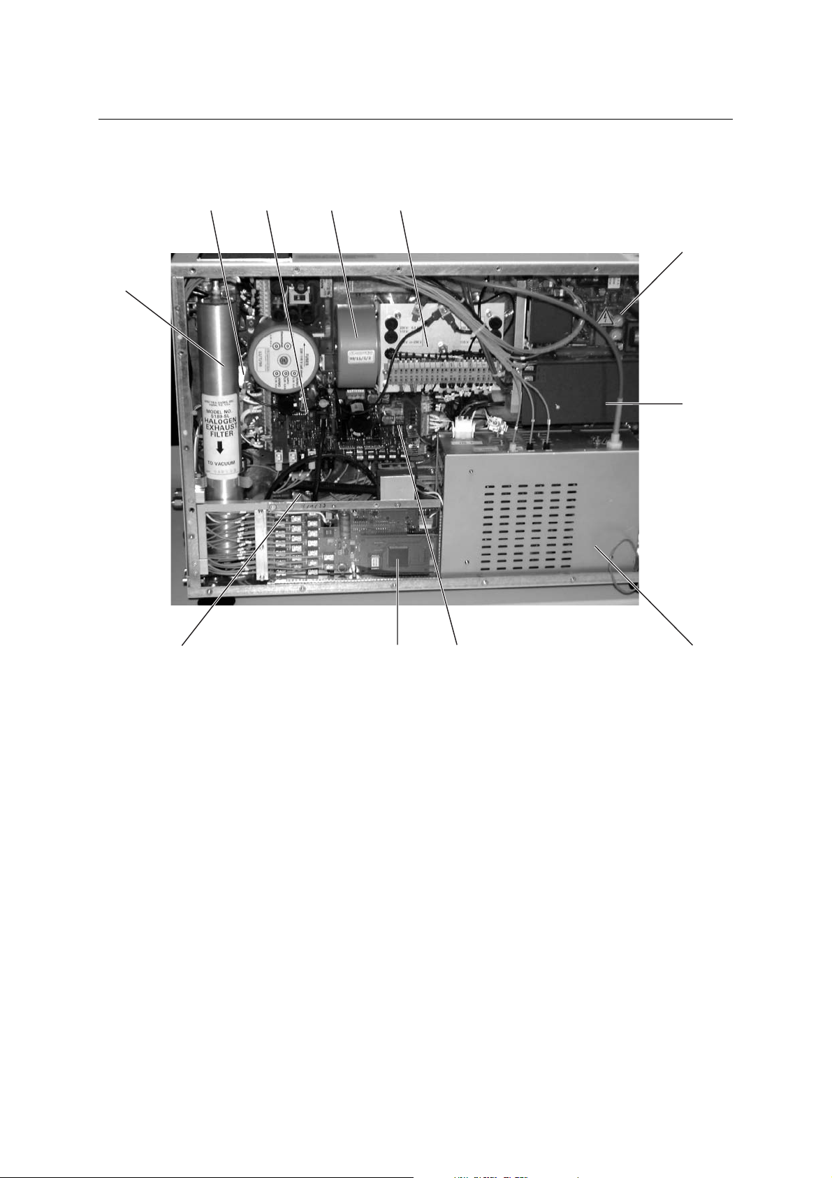
Figure 5: Electronics chamber (with servic e panel remo ved)
Key to Figure 5:
A Trigger board
B Thyratron supply board
C High voltage power supply module
D Gas supply unit
E Laser control unit
F Vacuum pump
G Halogen filter
H Mains filter
I Mains power supply unit
K Transformer
L Power distribution unit
DEF
C
16 User Manual OPTex
Page 27
2.5 Laser Control
The OPTex is controlled through an integral control device, known as
the laser control unit (CLS). This communicates with decentralized
submodules that perform dedicated functions (e.g. laser pulse
triggering).
Communication between the laser control unit and the decentralized
modules occurs through fiber optic light waveguides (FOLs). As the
FOLs do not pick up or transmit electromagnetic interference (EMI),
they provide a secure noise-free communication link. This is of
considerable importance as the fast high voltage (HV) discharges
required with excimer lasers create a high level of EMI.
The laser control software is stored on a flash prom mounted on the
laser control unit. This is interfaced to the operator through either the
optical RS232 in case of an OEM subassembly or through an
operating panel simulated on an PC (the software is provided). In the
following description “PC” also means Laptop.
Laser Control
A0507OPTex
LAMBDA PHYSIK - 07/2005 17
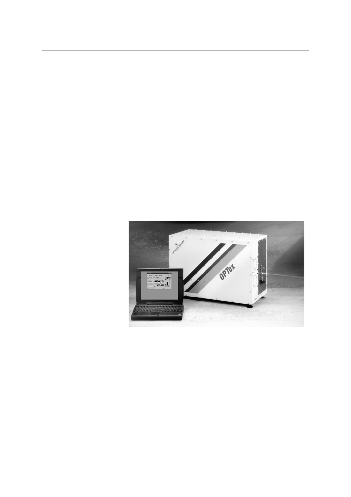
Figure 6: OPTex controlled through a Laptop
The OEM device’s controller unit or the existing PC is connected to the
laser control unit in the laser device through an optical RS232
interface. To convert the electrical signals emitted by the PC into the
optical signals required by the laser control unit and vice-versa, a
RS232 optical interface adapter is connected to a serial port on the
PC. This adapter is supplied as standard when operation thr ough a PC
is specified.
Page 28

LASER DEVICE FUNDAMENTALS
BA
2.6 Laser Tube
The NovaTube® can be considered as the motor of the laser. Figure 7
shows a cross section of the longitudinally symmetrical laser tube.
C
D
Figure 7: Cross section of the laser tube
The laser tube (C) is the reservoir for the laser gas. The materials
chosen allow the problem-free use of excimer gas mixtures. The
material surfaces become coated with a layer of halogen metal
complex. This process, resulting from a reaction between halogen
(laser gas) and metal (material within tube), is called passivation.
Passivation renders the material surfaces within the tube chemically
inert to halogen.
A repetition of this process, known as re-passivation, is always
required
– if the surface passivation has been damaged as a result of air
entering the laser tube
– (with multigas version only) if a change from a Fluorine to a Chloride
gas mixture is necessary
– when the laser device or laser tube has been transported or stored
for longer periods.
18 User Manual OPTex
Page 29

Laser Tube
A high voltage discharge between the electrodes (A) transfers the
energy to the excimer gas mixture (e. g. fluorine or krypton premix). In
order to obtain a controlled, spark-free discharge, the laser gas has to
be preionized, i. e. a sufficiently high density of free charged molecules
has to be created between the electrode s. Th is is ach ieved with
preionization pins (B) arranged along the main electrodes. The result
is a homogeneous preionization of the laser gas. The switching of
preionization and main discharge in series ensures a perfect
synchronization between preion iza tion an d ma in disch ar ge .
After the high-voltage discharge, thermal inhomogenities in the laser
gas arise in the discharge area. Therefore, the gas volume in the
discharge area has to be completely exchanged between two laser
pulses. A transverse circulation fan (D) positioned within the laser tube
causes the gas volume between the main electrodes to be completely
replaced between two successive laser pulses. The circulation fan is
driven externally via a magnetic coupling by a single-phase motor.
The energy efficiency of the excimer laser is to the order of 2%, i. e.
the main part of the energy supplied has to be carried away in the form
of heat. The gas heated up by the discharge is recooled to the correct
operating temperature (approx. 40 °C or 104 °F) using environmental
air.
The maintenance operations re qu ired during the lifetime of the
NovaTube
®
are new gas fills and the exchange of the windows. To
minimize downtimes, the windows should be stored as premounted
units.
A0507OPTex
LAMBDA PHYSIK - 07/2005 19
Page 30

LASER DEVICE FUNDAMENTALS
2.7 Thyratron
The laser uses a simple hydrogen thyratron, a thermionic tube. It is
used as an active switch to discharge the storage capacitors. The
anode of the thyratron is connected to the charging voltage. The
cathode is connected to ground. Between these two main electrodes is
the control grid, which initiates the discharge (switching) of the
thyratron.
As is also the case with conventional thermionic tubes, the cathode
structure has to be heated in order to ensure sufficient emission of
starting electrons. If the electron emission after a longer operating
period is no longer sufficient to initiate switching of the thyratron, this
can be corrected during the thyratron lifetime by increasing the heatin g
power of the cathode. Hydrogen is necessary to provide a fast current
increase and a high current intensity. However, as hydrogen is
continually lost due to diffusion and metal erosion, the concentration of
hydrogen has to be continually renewed. For this purpose, there is a
reservoir structure (palladium ) in th e tube, in which a large quantity of
hydrogen is stored. By heating the reservoir, hydrogen is released
from the reservoir into the main thyratron. It sh ould be note d, however,
that too much hydrogen reduces the hold-off voltage between the
electrodes of the thyratron to such a level that unwanted switching of
the thyratron will take place even without the trigger pulse. On the
other hand, if the partial hydrogen pressure in the thyratron is too low,
the laser is unable to pulse. This is because there is no discharge in
the thyratron due to a lack of charged particles.
The values for the two heating voltages, UH for the cathode heating
and UR for the hydrogen reservoir voltage, are critical to the correct
operation of the tube. The voltages are stabilized in a broad input
voltage range in order to be unaffected by voltage fluctuations in the
supply line (spikes). These values have to be altered during the total
life of the thyratron to ensure proper switching of the tube.
20 User Manual OPTex
Page 31

2.8 Energy Monitor
An energy monitor (where fitted) continually determines the beam
energy by sliding averaging of each of 16 pulses. The transient effect
takes less than 100 pulses. The energy monitor converts the
determined value into a digital value, for transmission through an FOL
link to the laser control unit.
As the energy monitor does not supply absolute measured values, it
has to be calibrated by means of a calibrated energy meter or power
meter. Apart from the additional energy and power detector, no further
measures are necessary. The necessary calibration procedure is
described in the maintenance section (Chapter 8).
2.9 Operating Modes
Energy Monitor
The pulse energy (output energy) of an excimer laser is dependent
upon the charging voltage (high voltage) and condition (age) of the
excimer laser gas.
If the pulse energy (E) is considered as a function of the charging
voltage (U), the result is approximately the function shown in Figure 8.
E[mJ]
x
x
x
x
x
U [kV]
x
x
Figure 8: Pulse energy as a function of charging voltage
As excimer laser gases age, the pulse energy obtained from a given
charging voltage will decrease.
A0507OPTex
LAMBDA PHYSIK - 07/2005 21
Page 32

LASER DEVICE FUNDAMENTALS
The laser can, therefore, run either in the Energy Constant mode ( EGY
CONST) or in the High Voltage Constant mode (HV CONST).
– If the Energy Constant mode is selected, the laser control
continuously adjusts the high voltage to achieve laser operation at a
preset energy level (see Figure 9).
Energy
HV
Figure 9: Voltage increase in the Energy Constant mode
High Voltage
Time
Energy
– If the High Voltage Constant mode is selected, the pulse energy
decreases with time as excimer laser gases have a limited lifetime
(see Figure 10).
HighVoltage
HV
Figure 10: Energy decrease in the HV Constant mode
Energy
Energy
Time
Most applications require the energy constant mode, whereas the high
voltage constant mode is primarily used for diagnostic purposes.
NOTE
The energy constant mode is only available if an energy monitor is
installed.
22 User Manual OPTex
Page 33

Safety Systems of the OPTex
2.10 Safety Systems of the OPTex
The laser device is provided with three safety circuits. Watch dogs are
monitoring laser operation. In case of faults they are not reset
automatically; laser operation will be interrupted and the warm-up
period will start again.
Faults are detected by hard- and software and classified into two
groups. The error messages are stored in the flagbytes of the laser
control software or indicated by the user shell WINLAC (see Section
6.1.3.3 on page 85). Pop-up text fields are giving some information
about potential reasons for these error messages.
Statical Errors
The error message “STATICAL ERROR” appears in case of the
following conditions or failures
– Remote (external safety) interlock,
– cover interlocks tube chamber or exceeding tube temperature,
– cover interlock electronics chamber or exceeding tempe rature in the
electronics chamber.
These signals are interrupting laser operation. All power supply lines
with more than 42 V DC and the mains supply line (except the housing
circulation power supply) are interrupted, the triggering is blocked.
Laser operation can be restarted when the cause of the error ha s been
rectified.
Operation Errors
The error message “OPERATION ERROR” qualifies the deviation of
laser operation parameters from limiting values concerning
– data transfer and processing
– HV charging time and HV value,
– leak rate,
– HV module temperature,
– Thyratron power supply,
– Overpressure in the laser tube (more than 4.5 or 4.1 bar).
These “Operation Errors” are stopping laser operation. After rectifying
the error the laser device has to be switched off by turning the key
switch and then on before laser operation can be restarted.
A0507OPTex
LAMBDA PHYSIK - 07/2005 23
NOTE
In case of overpressure in the laser tube the solenoid valves of the
valve assembly are closed automatically.
Page 34

LASER DEVICE FUNDAMENTALS
2.10.1 Safety Interlock
The Remote interlock circuit is supplied with 20 mA by an own power
supply unit. Interruption of the power supply line leads to an interlock
message.
2.10.2 Electronics Chamber
Closed housing and laser tube temperature are monitored by one
circuit and indicated by a common error message. For determined
service procedures the safety interlock has to be bridged by the
interlock defeaters.
Air cooling is adequate to laser operation only with closed front panel.
2.10.3 Tube Chamber
The laser device can operate only with closed housing of the tube
chamber. Interlock switches on the right, left and top service panel and
a temperature sensor near the laser tube are monitor ing the operation
status. Interlock and temperature errors are indicated by a common
error light.
When the tube chamber is open, all power supply lines with ≥ 42 V DC
and the mains supply line (≥ 100 V AC) are interrupted. For
determined service procedure s the safe ty int er loc ks ar e to be brid g ed .
The tube temperature is monitored by hardware components. If the
tube temperature exceeds 48 °C, an error message is generated, if it
reaches 60 °C, the current laser operation is interrupte d automatically.
In case of this interruption, the laser tube has to cool down to the
optimal operating temperature (40°C) before restarting any laser
operation. Depending on the environmental tempera ture this may take
approx. 30 minutes.
24 User Manual OPTex
Page 35

3SAFETY
Never switch on or attempt to operate or service the OPTex
before reading, understanding and fully familiarizing yourself
with the contents of this chapter.
This chapter is divided into three sections:
– General Safety Aspects, which explains aspects relating to the safe
operation of the laser device.
– Special Safety Aspects, which outlines the risks specific to working
procedures with and on this laser device.
– Overview of safety-relevant labels, which shows the design of and
describes the safety labels.
General Safety Aspects
3.1 General Safety Aspects
3.1.1 Basic Operation and Designated Use
The OPTex laser device has been built in accordance with state-ofthe-art standards and the recognized safety rules. Nevertheless, its
use may constitute a risk to life and limb of the user or of third parties
or cause damage to other material property.
WARNING
Potential eye and skin burns!
Only use the laser in accordance with its designated use. Safety
interlocks are only to be defeated by authorized personne l.
WARNING
Electrical hazard!
Safety interlocks are only to be defeated by authorized
personnel.
A0507OPTex
LAMBDA PHYSIK - 07/2005 25
WARNING!
Toxic hazards!
The gas system of an excimer laser contains a mixture of
halogen gases (fluorine or hydrogen chloride). Inhalation of, or
skin contact with, halogen gases should be avoided.
Page 36

SAFETY
The OPTex must only be used in technically perfect condition and in
accordance with its designated use and the instructions set out in this
manual, and only by safety conscious persons who are fully aware of
the risks involved in operating the laser device. Any functional
disorders, especially those affecting the safety of the laser device,
should therefore be rectified immediately.
The OPTex is primarily designed for use in low duty-cycle operation in
medical and scientific applications. Using the laser device for purposes
other than those mentioned above is considered contrary to its
designated use. The manufacturer/supplier cannot be held liable for
any damage resulting from such use. The risk of such misuse lies
entirely with the user.
Operating the OPTex within the limits of its designated use also
involves observing the instructions set out in this manual and
complying with the inspection and maintenance directives.
3.1.2 Organizational Measures
In accordance with the valid national regulations for prevention of
accidents (in Germany: VBG 93, In the USA: ANSI Z 136.1) a
responsible person should be designated as the Laser Safety Officer
(LSO) with the responsibility to effect the knowledgeable evaluation of
laser hazards and to monitor and enforce their control.
The instruction manual must always be at hand at the place of use of
the OPTex laser device.
In addition to the operating instructions, observe and instruct the user
in all other generally applicable legal and other mandatory regu lations
relevant to accident prevention and environmental protection.
These compulsory regulations may also deal with the handling of
hazardous substances and the issuing and/or wearing of personal
protective equipment.
WARNING
Risk of serious injury through incorrect operation!
Personnel entrusted with work on the OPTex must have read the
instruction manual and in particular the safety instructions
before beginning work. Reading the instructions after work has
begun is too late.
The necessity of reading the instruction manual applies especially to
persons working only occasionally on the OPTex, e.g. during setting
up, service or maintenance.
Use protective equipment, e. g. protective eyewear, wherever required
by the circumstances or by law.
26 User Manual OPTex
Page 37

General Safety Aspects
Ensure that all safety-relevant labels are attached to the laser device
in accordance with the label location diagrams in Section 3.4.1 on
page 48 and local regulations. Make sure that these labels are always
complete and perfectly legible. If any labels are missing, immediately
inform Lambda Physik.
In the event of safety relevant modifications or changes in the
behaviour of the OPTex during operation, stop the laser device
immediately and report the malfunction to the competent authority/
person (e.g. Lambda Physik Service).
Never make any modifications, additions or conversions which might
affect safety without the suppliers approval. This also applies to the
installation and adjustment of safety devices and valves.
Spare parts must comply with the technical requirements specified by
the manufacturer. Spare parts from original equipment manufacturers
can be relied upon to do so.
Never modify the software of programm abl e co nt ro l syste ms .
Adhere to prescribed intervals or those specified in the instruction
manual for routine checks and inspections.
For the execution of maintenance work, tools and workshop
equipment adapted to the task on hand are absolutely indispensable.
3.1.3 Selection and Qualification of Personnel
- Basic Responsibilities
Make sure that only authorized personnel works on or with the OPTex
laser device. Statutory minimum age limits must be observed.
Employ only trained or instructed staff and set out clearly the indivi dual
responsibilities of the personnel for operation, set up, maintenance
and repair.
Do not allow persons to be trained or instructed or persons taking part
in a general training course to work on or with the OPTex laser device
without being permanently supervised by an experienced person.
WARNING
Potential electrical hazards!
Work on the electrical system and equipment of the OPTex laser
device must be carried out only by a skilled electrician or by
instructed persons under the supervision and guidance of a
skilled electrician and in accordance with electrical engineering
rules and regulations.
A0507OPTex
LAMBDA PHYSIK - 07/2005 27
WARNING
Toxic hazards!
Work on gas fuelled equipment may be carried out by specially
trained personnel only.
Page 38

SAFETY
3.1.4 Safety Instructions Governing Specific Operational Phases
Take the necessary precautions to ensure that the OPTex is used only
when in a safe and reliable state.
Operate the laser device only if all protective and safety oriented
devices, such as removable safety devices, emergency shut off
equipment and exhausters, are in place and fully functional.
In the event of malfunctions, stop the laser device immediately and
lock it. Have any defects rectified immediately.
Before starting the OPTex laser device ensure that nobody is at risk.
Never switch off or remove suction and ventilation devices when the
laser device is in operation.
Observe the adjusting, maintenance and inspection activities and
intervals set out in the instruction manual, including information on the
replacement of parts and equipment. These activities may be
executed by skilled personnel only.
Brief operating personnel before beginning special operations and
maintenance work, and appoint a person to supervise the activities.
In any work concerning the operation, conversion or adjustment of the
OPTex and its safety oriented devices or any work related to
maintenance, inspection and repair, always observe the start up and
shut down procedures set out in the instruction manual and the
information on maintenance work.
Ensure that the maintenance area is adequately secured.
WARNING
Potential electrical hazards!
If the laser device is completely shut down for maintenance and
repair work, it must be secured against inadvertent st art in g .
Ensure that the electrical system is locked-out and tagged-out
prior to servicing by locking the key switch of the laser device
and tagging appropriate warning signs.
WARNING
Potential eye and skin burns!
If the laser device is completely shut down for maintenance and
repair work, it must be secured against inadvertent st art in g .
Ensure that the radiation system is locked-out and tag ged-out
prior to servicing by locking the key switch of the laser device
and tagging appropriate warning signs.
28 User Manual OPTex
Page 39

General Safety Aspects
CAUTION
Risk of gas leaks!
Switching off the laser device automatically closes the solenoid valves
in the laser device’s gas circuit. This interrupts the gas flow in the
laser device, but does not evacuate the circuits in the laser device.
Also, operating pressure remains in the external gas supply lines.
For additional safety, close the corresponding external gas shut-off
valves when locking out the laser device.
Always tighten any screwed connections that have been loosened
during maintenance and repair.
Any safety devices removed for set up, maintenance or repair
purposes must be refitted and checked immediately upon completion
of the maintenance and repair work.
Ensure that all consumables and replacement parts are disposed of
safely, with minimum environmental impact and in accordance with the
valid national and local regulations for waste disposal.
A0507OPTex
LAMBDA PHYSIK - 07/2005 29
Page 40

SAFETY
3.2 Specific Safety Aspects
Specific safety aspects are:
– the physical hazards related to the system
– the protection of the operators or users of the system against these
hazards
– the constructive protective measures against these hazards.
Lasers and laser systems are classified according to their relative
hazards. These classifications can be found in the American National
Standard for the Safe Use of Lasers (ANSI Z 136.1-1968), FDA 21
CFR 1040.10 and 1040.11, IEC-825 and in the European Standard
EN 60625.
Within this classification, the OPTex is a Class IV (high power) laser
device when operated with open covers during servicing conditions,
and must therefore be regarded as a potential hazard to the human
operator.
The laser beam must also be regarded as a potential fire hazard.
A Class IV laser system is not enclosed and therefore requires sever al
safety precautions. Class IV is the most powerful (and potentially
hazardous) category of lasers. Direct and scattered radiation from
Class IV products are considered acute ha za rd s to th e ey es an d skin .
Precautions include eye and skin protection, remote interlocks and
warning labels.
NOTE
The OPTex is a class IV laser device. However, when co nne cte d to an
OEM device or with housing closed, it becomes a Class I laser device.
A Class I laser device is defined as a laser system which is supplied
with a special enclosure which does not allow access to hazardous
levels of laser light during normal operation. This class of laser does
not require special precautions for eye safety during normal ope rations
as long as the protective enclosure is in place.
WARNING
Risk of serious injury!
A Class I laser system becomes a Class IV when the enclosure is
open.
The laser itself is a class IV device.
30 User Manual OPTex
Page 41

3.2.1 Physical Hazards
3.2.1.1 Ultra-Violet Light
WARNING
The laser beam is very dangerous to the eyes and skin!
The following are hazardous,
1. Direct radiation-light as it leaves the laser.
2. Reflected radiation-light which has hit a surface and bounced
off.
3. Diffuse radiation-light, which has hit a surface, bounced off,
and scattered.
Laser radiation is emitted as a narrow beam of almost parallel rays,
the intensity of which will remain high even at some distance of the
laser. Although the radiation is nonionizing, damage can still occur to
living tissue, if exposed for to long, as a result of heat produced during
radiation absorption.
Specific Safety Aspects
The radiation of an excimer laser lies outside the visible range.
Possible wavelengths of the high intensity ultraviolet radiation are
157 nm, 193 nm, 248 nm, 308 nm or 351 nm.
Operating the laser at 157 nm causes additional spontaneous and
stimulated emission of radiation in the range of 635 nm to 755 nm
(visible red).
In general, the maximum permissible radiation exposure for th e ski n is
several times greater than for the eye. Safety measures with regard to
the radiation hazard are therefore mainly based on dangers for the
eye.
A potential chemical hazard originates from interaction between the
laser beam and an obstruction. The high irradiance could result in the
liberation of hazardous fumes and gases. In addition, the heat
generated is sufficient to ignite many materials.
Not only is the direct laser beam hazardous, but unchecked reflections
of laser light also constitute a potential hazard. This risk is excluded if
the laser beam is contained within a protective enclosure. Protective
measures must be taken, therefore, when person ne l are wor king in an
open beam situation (use of beam shielding and beam dump).
A0507OPTex
LAMBDA PHYSIK - 07/2005 31
Page 42

SAFETY
3.2.1.2 High Voltage / Electric Energy
WARNING
Electrical hazards!
High voltages exceeding the Safety Extra Low Voltage levels
(SELV) of 42 VAC or 60 VDC introduce the potential hazard of
electric shock and might cause serious injuries by passing
electricity through the body.
High voltages of up to 14 kV are generated in the OPTex laser device.
As the equipment is provided with a protective housing, accidental
contact with current-carrying conductors during normal operation is
impossible. However, if an appropriate protective cover is removed,
potentially lethal hazards exist in spite of the existenc e of the housing
interlocks. With a protective cover removed, there is the risk of an
electric shock whenever the mains supply is connected and the high
voltage capacitors are charged. The capacitors in the laser device hold
some of joules at peaking voltages of up to 30 kV.
WARNING
Risk of electrocution!
Personnel should never open the laser device before the main
power supply cable has been disconnected and the high voltage
capacitors are completely discharged.
An electrical safety overview is given in Section 3.2.2.2 of this chapter
(page 38), but reference should also be made to Section 3.2.3 (page
42) for an overall description of the system safeguards.
In addition to the above mentioned hazards, the HV switch used
(thyratron) generates ionizing radiation.
Radiation limit: 0.2 mSievert/h at 10cm distance
32 User Manual OPTex
Page 43

3.2.1.3 Halogen Gases
WARNING!
Toxic hazards!
The gas system of an excimer laser contains a mixture of up to
5 % Fluorine gas or 0.5 % Hydrogen Chloride. Inhalation of, or
skin contact with, halogen gases should be avoided.
Halogen gases can cause severe chemical and thermal burns and in
sufficient concentrations can cause death due to respiratory damage
and pulmonary edema.
It is essential, therefore, that local safety regula tio ns co nc er nin g th e
emission of chemical vapors must be strictly observed along with the
recommendations made in this chapter and throughout this manual.
Depending upon the wavelength in which the laser is to be operated,
the halogen is either Fluorine or Hydrogen Chloride.
– Fluorine is in the form of a premix gas, ratio ≤ 5 % Fluorine in premix,
and diluted further with other gases in the laser. Fluorine is
characterized by an extremely stinging smell in very low
concentrations (0.1ppm).
Specific Safety Aspects
– Hydrogen Chloride (HCl) is in the form of a premix gas, ratio < 0.5 %
HCl in premix.
Both gases are still present in sufficient quantities in the gas supply to
cause serious injury if not correctly handled and used.
The attention of the user is drawn, therefore, to the following maximum
permitted exposure limits for Fluorine and Hydrogen Chloride. The
permitted periods of time in respect of these limits will depend on local
safety regulations.
The MAK (maximum acceptable concentration level) values according
to the German publication:
“Technische Regel des Ausschuß für Gefahrstoffe des
Bundesministeriums für Arbeit und Soziales (TRGS 900)”
and the PEL (permissible exposure limit) set by the American
government agency
Occupational Safety and Health Administration (OSHA)
are as follows:
F
limit: 0.1 ppm (0.2 mg/m3)
2
HCL limit: 5.0 ppm (7.5 mg/m
3
)
A0507OPTex
LAMBDA PHYSIK - 07/2005 33
NOTE
Refer to the International Chemical Safety Cards for Fluorine
(ICSC: 0046) or Hydrogen Chloride (ICSC: 0163), respectively, for
more precise health hazard information.
Page 44

SAFETY
The possibility of over-pressure of the gas mixture containing fluorine
or hydrogen chlorine creates potential hazards with the risk of leakage
from the laser tube and gas pipes. Under normal operating conditions
the overpressure is less than 2.4 bar (3.4 bar abs.), respectively
2.0 bar (3.0 bar abs.) for the F
version of the OPTex laser device. In
2
the event of a leak occurring, the release of halogen gas constitutes
the greatest hazard.
To remain even in a worst case under the MAK-value of 0.1 ppm for
Fluorine, non-ventilated rooms must have an air volume of at least
3
100 m
. For the installation in smaller rooms a sufficient air suction is
necessary.
Further potential chemical hazards exist due to the formation of
hydrofluoric acid if fluorine gas comes into contact with water.
Hydrofluoric acid can also be formed in the haloge n filte rs used in the
system due to Fluorine coming into contact with the hygroscopic
components of the filter.
3.2.1.4 Ozone
The formation of ozone due to the interaction of ultra-violet light (in
particular at 193 nm) with oxygen, and high voltage discharge,
constitutes a potential hazard.
The MAK (maximum acceptable concentration level) value according
to the German publication
“Technische Regel (TRGS 900) des Ausschuß für Gefahrstoffe des
Bundesministeriums für Arbeit und Soziales”
and the PEL (permissible exposure limit) set by the American
government agency
Occupational Safety and Health Administration (OSHA)
are as follows:
O
3
NOTE
Refer to the International Chemical Safety Card for Ozone
(ICSC: 0068) for more precise health hazard information.
limit: 0.1 ppm (0.2 mg/m3)
34 User Manual OPTex
Page 45

3.2.2 Personnel Safety
3.2.2.1 Ultra-violet Radiation Safety
An excimer laser emits high intensity pulsed ultraviolet radiation which
constitutes a hazard to personnel during periods of operation and
servicing. In addition, the F
radiation in the range from 635 nm to 755 nm, which represents a
particular danger.
WARNING
Risk of serious injury!
A Class I laser system becomes a Class IV when the enclosure is
open. The laser itself is a class IV device.
If alignment or maintenance work on Class IV laser equipment is
necessary, everyone in the laser area must wear appropriate
protective goggles or other appropriate protective eyewear. The
mandatory protective goggles provide protection against direct
radiation, reflected radiation and standard radiation (normal operating
conditions) within the respective wavelength range.
version of the OPTex emits visible red
2
Specific Safety Aspects
A0507OPTex
WARNING
Risk of serious injury!
Always wear goggles when there is a chance of exposure to
radiation from the laser.
Before putting on the protective goggles, check them for any
obvious defects. As the filter in the goggles provides protection
for only a narrow band of wavelengths, make sure you are
wearing the appropriate goggles for the laser device in question.
Check with your Laser Safety Officer or other safety personnel
for guidance in selecting the appropriate goggles.
Contact a manufacturer of protective eyewear for information about
appropriate protective eyewear. Specifications needed to select
appropriate eyewear are: wavelength, power, beam diameter,
repetition rate and max. pulse duration.
The ANSI (American National Standards Institute) standard for safe
use of lasers requires that protective goggles which block the
appropriate laser wavelength should be worn while operating or
servicing class IV lasers. The goggles should be clearly labeled with
an optical density and the specified wavelength.
To avoid confusion, these goggles should be kept separate from other
safety glasses and personal protective equipment. Using the wrong
type of goggles is dangerous. It can be worse to have improper
eyewear and a false sense of security than to have no eyewear and
take precautions based on the absence of protection. Even if you're
wearing protective goggles, never looked directly into the beam;
intense laser radiation is capable of destroying the protective filter.
LAMBDA PHYSIK - 07/2005 35
Page 46

SAFETY
Optical Safety Guidelines
WARNING
Potential eye burns!
Only use the laser in accordance with its designated use. Safety
interlocks are only to be defeated by authorized personne l.
The following guidelines describe some of the action s ne ce ssa ry to
avoid injury caused by the laser beam. Always follow these guidelines
and take additional precautions if necessary.
When eyewear is necessary, make sure it has the proper optical
•
density for the laser wavelength.
All other personnel in the vicinity of the laser should also be ordered
•
to wear protective eyewear. Only qualified personnel should be
permitted to operate the laser.
Never intentionally look directly into any laser beam.
•
Avoid indirect viewing of direct or reflected laser radiation. Specular
•
reflections (from reflective surfaces) can be as dangerous as the
direct laser beam. Do not view the beam through optical instruments
unless the optics are designed to filter the laser wavelength.
Precautions must be taken to ensure that there are no reflecting
•
objects in the path of the laser beam.
Do not deviate from standard operating procedures when working
•
with class IV laser equipment.
Use lasers only in approved applications and locations. Take
•
adequate precautions to prevent unauthorized personnel from
entering the area where a class IV laser is operating. Do not use
lasers around untrained personnel who may injure themselves
inadvertently. Ensure that all personnel in the area observed proper
safety precautions.
Do not assume the laser system is aligned. Misaligned optics can
•
cause unintended exposure.
Report all incidents of exposure to your supervisor.
•
Warning signs indicating the laser enclosed area should be clearly
•
displayed with an additional warning light outside the door.
Local and national regulations governing the safe use of lasers
•
should be adhered to all times.
36 User Manual OPTex
Page 47

Specific Safety Aspects
Skin Safety
WARNING
Potential skin burns!
Direct and reflected laser radiation can burn exposed skin.
Only use the laser in accordance with its designated use. Safety
interlocks are only to be defeated by authorized personne l.
Although the skin can withstand a considerably higher radiation
•
intensity than the eyes, tissue may be burned to a greater or lesser
degree, depending on the radiation time and the irra diation intensity.
Avoid contact between the skin and the beam, or specular
•
reflections of the beam. Reflections of the beam may be as
dangerous as the beam itself. Appropriate protective clothin g should
be worn to protect the skin whenever necessary.
Fire Safety
A0507OPTex
WARNING
Fire hazards!
Class IV lasers are, by definition, fire hazards.
The laser beam can cause flammable materials to ignite or
explode.
Always keep a fire extinguisher in the laser area in case a fire
occurs
Because of the high output power from the class IV laser, a wide range
of materials can be set on fire. Therefore, when the beam path is
open, appropriate fire prevention measures should be taken:
Combustible materials may be ignited by the laser beam or by
•
electrical components inside the laser system. Flammable items
must be isolated from the laser beam and from the laser system.
Paper (circuit diagrams, leaflets, or even posters on the wall),
•
curtains that are not coated with fire retardant, wooden panels or
similar materials can be easily set on fire by direct or re flected lase r
radiation.
Only beam stops made of non flammable materials (not asbestos!)
•
should be used.
Many fluids and solvents (e.g. cleaning agents used for
•
maintenance) are combustible. The intense beam of the laser or a
spark from an internal switch can ignite vapors from these materi als.
Prevent the laser beam from contacting flammable materials used in
the laser area.
Move containers of flammable materials as far from the laser system
•
as possible and shield them from the beam with opaque materials.
Under no circumstances should these solutions and vapors be
placed in the beam path or near the system.
LAMBDA PHYSIK - 07/2005 37
Page 48

SAFETY
3.2.2.2 Electrical Safety
WARNING
Electrical hazards!
If the laser device is completely shut down for maintenance and
repair work, it must be secured against inadvertent st art in g .
Ensure that the electrical system is locked-out and tagged-out
prior to servicing by locking the key switch of the laser device
and tagging appropriate warning signs.
High voltages of up to 14 kV are generated within the laser equipment.
The following precautions should be observed:
Local safety regulations must always be strictly complied with.
•
Switch off the OPTex immediately with an interlock switch or
•
Emergency Off (EMO) switch in case of an emergency, i.e. to
prevent injury or serious material damage, or if trouble occur s in the
electrical system (see Section 3.2.3.1 on page 42). Contact after use
of the interlock or EMO switch appropriate maintenance personnel
(e. g. safety officer).
Work on the electrical system or equipment may only be carried out
•
by a skilled electrician himself or by specially instructed personnel
under the control and supervision of such electrician and in
accordance with the applicable electrical engineering rules.
Fault finding and troubleshooting in high voltage circuits must only
•
be performed by trained personnel.
Necessary work on live parts and elements must be carried out only
•
in the presence of a second person who can cut off the power supply
in case of danger by actuating the emergency shut off or key switch.
Secure the working area with a red and white safety ch ain and a
warning sign.
Use insulated tools only.
If provided for in the regulations, the power supply to parts of the
•
OPTex laser device on which inspection, maintenance and repair
work is to be carried out must be cut off.
Before starting any work, check the de-energized parts for the
•
presence of power and ground or short circuit them in addition to
insulating adjacent live parts and elements.
Use only original fuses with the specified current rating.
•
The electrical equipment of the OPTex laser device is to be
•
inspected and checked at regular intervals. Defects such as loose
connections or scorched cables must be rectified immediately.
38 User Manual OPTex
Page 49

3.2.2.3 Gas Safety
WARNING!
Toxic hazards!
The gas system of an excimer laser contains a mixt ure of f luorine
or hydrogen chloride gas.
Inhalation of, or skin contact with, halogens should be avoided.
The properties of compressed gases, such as pressure, diffusibility,
make the handling of compressed gases hazardous. Laser gas
mixtures invariably contain components which are corrosive, toxic and
oxidizing. Therefore, extreme care must be taken when handling these
mixtures.
As a general guide to safe working practices, the following precautions
should be observed when working with gas equipment. Always follow
these guidelines and take additional precautions if necessary.
Gas protective equipment, such as masks, must be available at the
•
entrance to the area where the laser is located.
Ensure that a protective mask with a protective gas filter, or a
complete breathing apparatus set, is placed in a clearly displayed
and accessible part of the operating area.
Specific Safety Aspects
A0507OPTex
It is recommended that personnel work in pairs a nd within sight and
•
sound of each other, although not necessarily in the same working
area. Only trained and competent personnel should be permitted to
handle premix gas cylinders and regulators.
Any equipment to be used for halogen gas se rvic ing sho uld be
•
thoroughly cleaned, degreased and dried before use, then treated
with increasing concentrations of halogen gas so that any impurities
can be burned off without the risk of the equipment catching fire.
Any equipment that has contained fluorine must be thoro ughly
•
purged with helium or argon and evacuated prior to opening or
refilling.
Due to the possibility of over-pressure of the gas mixture containing
•
halogens, potential hazards exist due to the risk of leakage of the
laser cavity and gas pipes. The most vulnerable part is the window.
Under normal operating conditions the pressure is 3.4 bar (4.4 bar
abs.) or, for the F
must be used such that the beam exit is not directed at personnel. In
the event of a leak occurring, the release of halogen gas constitutes
the greatest hazard.
Avoid repeated bending and excessive vibration of gas piping and
•
equipment as this can result in flaking of the protective halogen film
and rupturing of the metal. This could lead to the occurrence of a
fluorine metal fire. Flaking of the protective film can also cause du st
to foul the valves.
version, 2.8 bar (3.8 bar abs.). The equipment
2
All areas containing pressurized halogen gas mixtures should be
•
inspected for leaks periodically (weekly).
LAMBDA PHYSIK - 07/2005 39
Page 50

SAFETY
All leaks should be repaired immediately, but not while the system
•
contains halogen gases.
For Fluorine: Ammonia vapor expelled from a squeeze bottle
containing ammonium hydroxide may be used to detect leaks at
suspected points.
Filter paper moistened with potassium iodide solution is a very
sensitive means of detecting fluorine in concentrations as low as
approximately 25 ppm. The potassium iodide paper should be held
with the aid of a long tongs or forceps, and will darken and turn black
when fluorine is present. Fluorine odor is sufficiently strong to be
detectable in very low concentrations (at 0.14 ppm). Fluorine will
also fume readily in air.
Adequate ventilation is essential. See the corresponding
•
“Installation Conditions” manual for the specifications of the required
air flow.
WARNING
Toxic hazard!
Ensure that the laser is ventilated into an appropriate exhaust.
Make sure that the exhaust of the laser is not connected to the
duct system of systems used for the processing of breathing air
(e. g. air conditioning or ventilating systems).
Ozone can be generated by high power ultra-violet radiation (in
•
particular with ArF, at 193 nm). This gas should be removed with a
proper air exhaust or by flushing the beam path with Nitrogen or
Argon.
Adequate ventilation is essential. There should be at least 10 air
•
changes per hour when the laser device is installed in a confined
space, e.g. housing of additional devices.
Always wear protective gloves when changing halogen filters as they
•
are hygroscopic and contain oxidizing agents.
As the premix gas contains halogen, a needle valve or cut-off valve
•
should be installed in the premix gas line. The additional valve is to
be located near the gas cylinder to protect the gas line and pressure
regulator against corrosion and provide additional gas protection. Do
not solely rely on the main gas cylinder valve to provide adequate
protection.
Gas cylinder valves should be closed except while filling the laser, or
•
when running the laser in the constant energ y mo de (EGY Co ns t.) .
The pressure regulator, situated between the external gas cylinder
•
and the laser, should be checked regularly. The maximum permitted
value while cylinders are opened is 5.2 bar (abs).
40 User Manual OPTex
Page 51

3.2.2.4 Pressure Safety
Gas pressures of up to 7.5 bar (absolute) are permitted on the valve
assembly and up to 5.2 bar (abs.) on the gas inlet.
Specific Safety Aspects
Gas pressures of up to 4.4 bar (abs.) or, for the F
(abs.) are permitted in the laser tube. If pressure rises above that, the
laser device is switched off automatically. The following precautions
should be observed:
The laser should only be operated with the housing closed.
•
In accordance with the local pressure vessel regulations (in
•
Germany: “Druckbehälterverordnung”), Lambda Physik
recommends to have the laser tube checked by a specialist every
five years.
3.2.2.5 Seismic Protection
For installations in areas that are susceptible to seismic activity, the
end user is responsible for appropriately securing the laser device
within their facility or the OEM is responsible if the laser device should
be installed within an OEM device, alternatively. For the exact
configuration of the protective devices, local regulatory requirements
are to be followed and the site vulnerability of the facility or OEM
device (e.g. soil conditions and design) is to be taken into account.
Provision is to be made for the following:
Anchors to prevent movement or overturning of the laser device
•
during a seismic event.
version, 3.8 bar
2
A0507OPTex
Suitable strain relief devices for all supply lines to control the risks
•
through leakage or escape of gases, liquids and electricity etc.
during a seismic event.
Specific information regarding the position of the mounting holes and
laser device feet is contained in Section 4.2 on page 52.
LAMBDA PHYSIK - 07/2005 41
Page 52

SAFETY
3.2.3 Constructive Safety Features
The laser device is equipped with the following constructional safety
features:
3.2.3.1 Radiation Safety Features
Appropriate Class IV label affixed to laser device enclosure (see
•
Section 3.4 of this manual).
All parts of the laser where laser radiation may possibly escape are
•
marked with the appropriate adhesive danger signs (according to
IEC 825).
Red LASER ON indicator lamp on the left-hand side of the laser
•
device
When the laser is ready for the emission of radiation or if it is emitting
radiation, the LASER ON indicator lamp (see Figure 11, A) is
illuminated.
A B
Figure 11: LASER ON indicator lamp and interlock connector
OPTex series lasers are provided with a connector (”Interlock”) on
•
the left-hand side (see Figure 11, B).
This enables connection to external electrical circuits for a warning
light and an interlock or Emergency Off (EMO) switch.
The external warning light signals that the las er is opera ting an d
therefore warns of the risk of laser radiation. The external interlock
or EMO switch shuts down the laser, for instance in case of
emergency or if a door connected with the switch is opened.
42 User Manual OPTex
Page 53

Specific Safety Aspects
The beam exit from the laser housing can be closed by a manually
•
operated beam shutter (see Figure 12, A).
A
Figure 12: Shutter on laser device’s beam exit
All service panels at the laser are equipped with interlock switches
•
which will shut off high voltage (more than 42 VDC and more than
100 VAC) if a panel is opened during laser operation. This stops the
laser radiation immediately.
3.2.3.2 Electrical Safety Features
The following safety features protect the user from the potentially
lethal hazards associated with high voltage power sources.
All potentially lethal voltages are contained in fully protected and
•
grounded enclosures. Additionally a chassis cover interlock disables
the high voltage power supply when the cover is removed.
Opening a service panel triggers an interlock switch that shuts off the
•
high voltage and, consequently, the laser radiation.
For servicing, the capacitors shall be discharged to ground thro ug h
•
a safety stick. The safety stick and the discharge connector are
located behind the right-hand service panel (beam exit side).
A0507OPTex
LAMBDA PHYSIK - 07/2005 43
All AC power wiring is UL-recognized and rated at 1500 V. Black is
•
used for line phases, yellow-green is used for ground and black for
neutral.
Each AC power module has a yellow-green grounding conductor.
•
Page 54

SAFETY
The Power Module shielding encloses the HV parts of the laser to
•
protect the surroundings against ionizing radiation and
electromagnetic interference (limits, see Section 3.2.1.2 on page
32). A fully enclosed laser housing shields the surroun dings from the
ionizing radiation.
All AC power connectors are labeled for identification. AC power and
•
signal lines are never combined in the same connector.
3.2.3.3 Pressure and Gas Handling Safety Features
The Lambda Physik Excimer Laser incorporates the following pressure
and gas handling features:
The pressure chamber is designed in accordance with the official
•
German pressure vessel regulations, the Druckbehälterverordnun g
(”Allgemeine Vorschrift, DruckbehV”; edited by the
”Bundesministerium für Arbeit und Soziales”; Germany).
Every chamber is tested up to 4.5 bar (abs).
Gas valves are electrically operated.
•
The tube housing is fully interlocked.
•
All gas fittings are 6 mm Gyrolok.
•
A powerful ventilation system causes continuous underpressure in
•
the tube chamber during laser operation . Th is pr ev en ts toxic gas
from escaping into the ambient air in case of a leak.
The exhaust enclosure is designed to ensure ventilation of all
•
components.
3.2.3.4 Fire Safety Features
The fire safety features designed into Lambda lasers eliminate the use
of materials which are combustible or produce toxic vapors as well as
preventing flames from spreading or burning materials from dripping.
The design incorporates the following specific fire safety features:
Polyvinyl chloride (PVC) is not used.
•
No ventilation holes in fire break enclosures are in excess of 5 mm
•
(0.20") in diameter. Hole arrays are used as required.
Material meeting or exceeding UL 94-V1 is used.
•
44 User Manual OPTex
Page 55

3.2.3.5 Mechanical Safety Featur es
Mechanical safety design provides prot ect ion ag ainst an y ha za rd s
which could cause physical injury or burns. Specific mechanical safety
features are listed below:
Exposed corners are radiused.
•
Air fans have grill guards with less than 6.4 mm (0.25 in).
•
No high temperature components are accessible to touch.
•
The laser center of gravity is centrally located within the enclosure to
•
minimize tipping hazard.
Threaded holes are provided in the base of the housing to allow
•
suitable seismic anchorage of the laser device.
3.2.3.6 General Safety Features
Specific Safety Aspects
The OPTex incorporates the following general safety features:
Key-switch controlled laser operation (see Figure 13, A).
•
The laser device can only be switched on with the key-switch. This
prevents inadvertent or unauthorized starting of the laser. It cannot
be operated with the key in the OFF position and the key can not be
removed in the ON position.
A
A0507OPTex
LAMBDA PHYSIK - 07/2005 45
Figure 13: Key switch
No polychlorinated biphenyl (PCB) is used.
•
No asbestos is used.
•
Page 56

SAFETY
3.3 Safety Compliance List
The equipment has been tested and found to comply with the limits of
the European Council Directives about bringing the laws of the member
states into line relating to electromagnetic compatibility (89/336/EEC)
and low voltage (73/23/EEC).
The OPTex complies with the following standards:
EN 50082-1 (electromagnetic immunity)
•
EN 50081-1 and EN 55011 (electromagnetic emission and radio
•
disturbances)
EN 61000-4-2 (electrostatic discharge)
•
ENV 50140 and ENV 50141 (radiated susceptibility)
•
EN 61000-4-4 (fast transient bursts)
•
EN 61010-1 (safety requirements for electrical equipme nt for
•
measurement, control and labo ra to ry us e)
from the EN 60601 series (safety requirements for medical electrical
•
equipment), if applicable:
– EN 60601-1 (general requirements for safety)
– EN 60601-1-4 (collateral standard: programmable electrical
medical systems)
– EN 60601-2-22 (particular requirements for the safety of
diagnostic and therapeutic laser equipment).
All laser products from Lambda Physik are also comp at ible with th e
European laser safety standard EN 60825.
46 User Manual OPTex
Page 57

3.4 Labels
This chapter contains information about the safety-relevant labels
attached to the OPTex.
– Section 3.4.1 shows the design of the safety labels and indicates
their respective part numbers and physical location on the laser
device.
– Section 3.4.2 contains a plain-langua g e de scr ipt ion of ea ch safe ty
label. These descriptions are grouped in label part number order.
Ensure that all safety labels are affixed to the laser device in
accordance with the Label Location Diagrams in Section 3.4.1 of this
chapter.
WARNING
Missing labeling can cause injury!
If warning labeling is missing or incomplete, persons are not
made aware of potential exposure to specific hazards. Make sure
that all warning labels are affixed to the laser device according to
the plans given in this chapter. Do not put the laser device into
operation if labeling is incomplete. Immediately replace the
missing warning label(s) or inform Lambda Physik.
Labels
A0507OPTex
Each label indicated on the label location diagrams has a part number
that provides a cross reference to the description and reproduction of
the label that is contained in the second subsection.
NOTE
To simplify the ordering of labels, the appropriate Lamdba Physik part
number is indicated together with the label de sc rip tio n.
LAMBDA PHYSIK - 07/2005 47
Page 58

SAFETY
3.4.1 Label Location Diagrams
DANGER
VisibleAndInvisible Laser Radiation
When Open AndInterlock Defeated
Or Failed
AVOIDEYE OR SKIN EXPOSURETO DIRECT
OR SCATTERED RADIATION
#906134
OPTex
Modell:
Model
XXXX
Serien-Nr.:
Serial-No.
YYYY
Hergeste llt:
Manufactured
115 / 2 30
V
50 / 60
Hz
#90574302
Lambda PhysikGmbH
Hans-Böckler-Stra e 12
ö
D-37079Gö ttingen
LASERTECHNIK
Phasen: Leiter:
Phases
Germany
inGöttingen
ö
13
~
1.66
ß
ö
This product complies with FDA
radiation performance standards
21 CFRChapter 1, Subchapter J
THIS LASERORITS COMPONENTS ARE
PROTECTED BY ONE OR MORE PATE NTS.
OTHERPATENTS ARE PENDING.
#90103401#905910
Wires
AkVA
AVOID EXPOSURE
VISIBLE AND INVISIBLE LASER
RADIATION IS EMITTED FROM
THIS APERTRE
#90613301
#906484
VISIBLE AND INVISIBLE
LASERRADIAT ION
AVOIDEYE OR SKIN EXPOSURETO
DIRECT OR SCATTERED RADIAT ION
Max. Average Power:
Output: J/pulse
Duration to ns
Wavelength
CLASS IV LASER PRODUCT
0.05
550
157 800
to
8
W
nm
#901032
Figure 14: Labels on front, left and top of the OPTex
48 User Manual OPTex
Page 59

DANGER
VisibleAndInvisible Laser Radiation
When Open AndInterlock Defeated
Or Failed
AVOIDEYE OR SKIN EXPOSURETO DIRECT
OR SCATTERED RADIATION
#906134
Labels
Figure 15: Labels on rear, right and top of the OPTex
A0507OPTex
LAMBDA PHYSIK - 07/2005 49
AVOID EXPOSURE
VISIBLE AND INVISIBLE LASER
RADIATION IS EMITTED FROM
THIS APERTRE
#90613301
Before contact:
-Discharge
-Earth
- Short circuit
#907378
NOTE
Label #907378 is attached to the protection grill inside the laser device
housing.
Page 60

SAFETY
3.4.2 Description of the Labels and Safety Labels
LP Part no.: Description:
# 901032 Safety label in accordance with CDRH. Contains
warning of laser radiation as well as data specific to
the laser device.
# 90103401 Label guaranteeing that this laser complies with FDA
radiation performance standards.
# 90574302 Laser device type plate indicating model, serial
number, date and place of manufacture and prin cipal
electrical supply data.
# 905910 Label showing that this laser and some of its
components are protected by patents.
# 90613301 Beam output safety label informing of the presence
of laser radiation when the aperture is open (2
labels).
# 906134 Label warning of the presence of laser radiation
when service panels are removed (3 labels).
# 906484 Label indicating that the laser device has to be
disconnected from the mains (remove mains plug
from mains wall socket) before opening the device.
# 907378 Label indicating that the discharge capacitors have
to be grounded (discharged) before removing the
protection grill and touching components behind.
50 User Manual OPTex
Page 61

4 SPECIFICATIONS AND
REQUIREMENTS
To continuously optimize the laser devices, all data contained in this
chapter are subjects to changes.
Should information on separate sheets (e.g. laser data sheets)
attached to or provided together with this instr uction manual contra dict
the information in this chapter, the information on the separate data
sheets has priority.
4.1 Specifications
All indicated data has been measured with an energy monitor and
optimized gas mixtures.
Parameter F
2
ArF KrF XeCl
a
Wavelength 157 193 248 308 351 nm
XeF
a
Specifications
Units
CDRH Class. IV IV IV IV IV –
Max. pulse energy
Max. repetition rate 200 200 200 200 200 Hz
Average power
Pulse duration
(nominal)
Pulse-to-pulse
energy stability
Beam dimensions 7 x 3.5
Beam divergence
A0507OPTex
b
1.51322108 mJ
c
0.24 2 4 1.8 1.6 W
5 - 108888ns, FWHM
< 2< 2< 2< 2< 2%
d
e
g
3 x 1 2 x 1 mrad (v x h)
a. all values in column are preliminary and not yet verified through tests, permitted tolerance: -15 %
b. measured at low repetition rate (5 Hz) at 100 % HV, for F
c. measured at max. repetition rate, for F2: includes < 4 % emission of red light
d. sigma; 100 % HV at 100 Hz
e. typical value, FWHM
f. typical value, FW 1/e
g. FWHM best focus
2
at beam exit
7 x 4
f
available
on request
2
available
on request
: includes < 4 % emission of red light
available
on request
mm2 (v x h)
LAMBDA PHYSIK - 07/2005 51
Page 62

SPECIFICATIONS AND REQUIREMENTS
4.2 Physical Dimensions
Figure 16 shows an overview of the dimensions and beam exit position
of the OPTex laser device. Detailed information is given in Figures 17
and 18 on the following pages.
h
b
l
w
Figure 16: Dimensions of laser device
c
Size a (l x h x w) approx. 600 mm x 400 mm x 300 mm
Weight 60 kg for F
version and OPTex2
2
55 kg for all other versions
Beam exit position
- vertical (b)
b
160 mm (± 1 mm)
- horizontal (c) 103 mm (± 1 mm)
Laser device feet
- height 23 mm (+ 5 mm)
- diameter 45 mm
Distance between feet
c
- upright position (l x w) 540 mm x 233 mm
- on side (l x h) 540 mm x 340 mm
a. not including feet, beam guidance system, key switch, earning lamp etc.
b. from lower edge of laser device housing
c. The laser device is tiltable by 90° to the side. In upright position, the
bottom side is provided with location holes (M8, see Figure 18).
52 User Manual OPTex
Page 63

O P
T
e
x
50 600
Physical Dimensions
400
O PTex
+5
23
Figure 17: Front and side views
A0507OPTex
160
INTERLOCK
RS232
3001,5
PREMIX
INERT
103
POWERON
FUSE2x6.3 WLASEREMISSION
INDICATOR
INERTPREMIX
RS232 INTERLOCK
LAMBDA PHYSIK - 07/2005 53
Page 64

SPECIFICATIONS AND REQUIREMENTS
Mounting threads, M8, length<15mm
(for rigid mounting oflaser device on an externalframe)
30
300
37
600
30
130.85 130.85
± 0.2
50
100
130
ø9.5
ø7
ø12
30
103
Recesses
for feet, M12
Tube mounting hole,
M6 screws inside
Tube adjustment screws, M6
(don't remove for tube exchange!)
Figure 18: Bottom view of the OPTex
4.3 Electrical Power Supply
Input voltage
(+ 10 % / -15 %, one phase) 230 VAC
Frequency 50 or 60 Hz
Apparent load 1.5 kVA
nominal current at 230 V 3 A
Fuse rating for each phase 6.3 A
or:
Input voltage
(+ 10 % / -15 %, one phase) 115 VAC
Frequency 50 or 60 Hz
Apparent load 1.5 kVA
nominal current at 115 V 6 A
Fuse rating for each phase 10 A
Type of mains plug IEC standard
54 User Manual OPTex
Page 65

4.4 Remote Control Interlock
The OPTex is provided with a remote interlock socket on the back
panel. This enables the laser device to be connected to an external
interlock circuit, Emergency Off (EMO) switch or warning light.
The number and location of external interlo ck swit che s ha s to be
determined in accordance with safet y req u ire me n ts at the las er
installation site. Each installation has a unique configuration.
The necessary plug for the remote interlock circuit is a male 9 pin sub
D plug. Pins 1 and 2 serve as power supply for the external laser
radiation warning lamp (max. 3 VAC, 50 mA). Pins 3 + 5 serve as
connection for the remote interlock circuit.
Remote Control Interlock
A0507OPTex
LAMBDA PHYSIK - 07/2005 55
External
laser radiation
warning lamp
Figure 19: Remote interlock socket
To enable laser operation it is necessary to short circuit pin 3 and 5
through a bridge (the appropriate p lug is en closed in your tool ca se) or
an external switch. If not, laser high voltage is disabled immediately
with an interlock message.
12
3
Remote interlock
(e. g. door switch)
5
Page 66

SPECIFICATIONS AND REQUIREMENTS
4.5 Controller Requirements
An RS 232 optical interface adapter is required to convert the electrical
signals from the PC into light signals for the OPTex and vice-versa.
This convertor is supplied as standard with laser devices which are to
be PC controlled.
Specifications of the convertor:
Connector to PC 25 pin sub-D, male
Connector to laser device 2 pin FOL plug
Length of FOL links 1.5 m (longer on request)
Power supply max. 7.5 VDC, max. 400 mA
The RS 232 optical interface adapter is to be plugged into a free
RS232 serial interface on the PC.
When using a PC to control the OPTex, the minimum requir ements for
the PC are:
Hardware IBM compatible 386 or higher
4 MB RAM, 1 MB available hard disk
memory
Mouse
Free 25 pin RS232 serial interface
(COM port)
Vacant slot in PC housing (for internal
mains supply)
3.5” floppy disk drive
Operating system Windows 3.x, Windows 95 or
Windows NT
Options 25 pin to 9 pin interface adapter (when
the only free RS232 interface (COM
port) is 9 pin)
Step down transformer (line voltage to
6VDC)
As the laser control software runs under Windows
connected to COM1, we recommend plugging the convertor into
COM2.
As standard, the convertor draws its current from the PC. For this, a
vacant slot is required in the PC. An additional mains socket is,
therefore, required near to the PC. As an option, the convertor can
draw its current from the mains. A suitable transformer is provided.
®
and the mouse is
56 User Manual OPTex
Page 67

External Trigger In and Pre-Trigger Out
4.6 External Trigger In and Pre-Trigger Out
The laser device can be connected to an external trigger generator
and/or a device requiring a pre-trigger imp uls e. T o conve rt el ec tric al
signals from external devices to optical signals required by the laser
device and vice-versa, use the TWE trigger convertor. The trigger light
pulses are transferred to the laser device by using FOL’s.
4.6.1 TWE Trigger Converter (Option)
The TWE trigger converter is a battery-operated device, which is
optically connected to the dedicated trigger in sockets on the laser
device and electrically connected to the external device(s). The
specifications of the TWE trigger converter are:
Weight approx. 150 g
Electrical connectors BNC/B (50 Ω)
Optical connectors approx. 1.5 m / HP
Battery Alkaline, 9 V 9.0 (F22)
≥ 6 months lifetime
Operating temperature 15 to 65 °C
External Trigger In Signal
The external trigger in signal triggers the OPTex from an external
trigger generator. The specifications for the electrical input and optical
output on the TWE trigger converter are:
Electrical input
- Voltage +2 to +5 V
- Impedance 50 Ω
- Pulse width ≥ 300 ps
Optical output
- Power 50 µW (665 nm)
- Pulse width ≥ 4 µs
- Repetition rate ≤ 200 Hz
- Delay typ. 30 ns
A0507OPTex
LAMBDA PHYSIK - 07/2005 57
Page 68

SPECIFICATIONS AND REQUIREMENTS
Pre-Trigger Out Signal
This signal is a pre-trigger impulse that is sent from the OPTex to an
external device. The specifications for the optical input and the
electrical output on the TWE trigger converter are:
Optical input
- Power 1 µW (665 nm)
- Repetition rate ≤ 200 Hz
- Delay typ. 25 ns
- Synchronization Electrical pre-trigger pulse occurs
Electrical output
- Voltage ≥ +3.5 V
- Impedance 50 Ω
- Pulse width ≥ 1 µs
approx. 100 ns before the laser pulse
58 User Manual OPTex
Page 69

4.7 Gas Requirements
The active medium in an excimer laser is a mixture of a rare gas, a
halogen gas and a buffer gas. This gas mixture is to be supplied to the
OPTex from a premix gas cylinder.
The gas mixture needed depends upon the wavelength in which the
laser is to be operated:
Gas Mixture Wavelength
F
and He 157 nm
2
and Ne
Ar, F
2
Kr, F
and Ne
2
Xe, HCl, H
Xe, He, F
a. Lambda Physik is owner of US Patent #4,393,505. This patent
covers the use of neon as a buffer gas to enhance excimer laser
performance.
b. Lambda Physik is the exclusive licensee under US Patent
#4,340,968. This patent covers the use of hydrogen as an additive
to improve Xenon Chloride laser performance.
a
a
b and Ne
2
and Ne
2
a
a
Gas Requirements
193 nm
248 nm
308 nm
351 nm
A0507OPTex
The OPTex is prepared for operation at a single wavelength. It can,
however, be subsequently modified at the factory to operate at a
different wavelength.
Ensure that the appropriate gas mixture is available.
In addition to the cylinder of premix gas, a cylinder of inert gas
(Helium) is required for flushing.
LAMBDA PHYSIK - 07/2005 59
Page 70

SPECIFICATIONS AND REQUIREMENTS
4.7.1 Gas Lines
The copper pipes (length: 2.4 meters) provided to connect the laser
device to the gas supply are only intended for initial commissioning.
For the permanently installed laser device, use internally
electropolished stainless steel pipes as specified below instead of the
copper pipes.
CAUTION
Contaminated gas tubing can pollute the laser tube!
Keep all gas tubing, especially the tubing for premix gases containing
halogen, free of dust, humidity, oil or other pollutants.
Gas connections 6 mm Gyrolok
Max. permitted pressure
on the gas inlet 5.2 bar (abs.)
Gas tubing
(recommended)
4.7.2 Pressure Regulators
Pressure regulators are supplied by gas manufacturers. Lambda
Physik recommends pressure regulators which are designed to
operate within the pressure range of the respective gas. The back
pressure has to be 5 bar (70 psi).
The joints for the gas pipes have to be provided with Gyrolok
for a pipe diameter of 6 mm.
CAUTION
Halogen gas corrodes most metals!
Always use stainless steel pressure regulators with gas mixtures
containing halogens.
®
stainless steel
(ALT ASTM A 269; material: 1.4404/316L;
surface: RA ≤ 0.4)
degreased and internally electropolishe d,
6 mm outer diameter
®
-fittings
4.7.3 Gas Cabinets
The risk of leakage from gas cylinders, particularly those containing
fluorine and hydrogen chloride gas mixtures is a potential safety
hazard. To minimize this hazard, safety gas cabinets are available.
Please contact the gas manufacturers for further information.
60 User Manual OPTex
Page 71

4.7.4 Gases Required (Premix)
The performance of the excimer laser depends on:
– quality of the gases used
– tightness of the gas installation
– cleanness of the gas equipment.
Gas purity and gas mixture have a decisive influence on:
– pulse energy and pulse-to-pulse stability
– laser power
– gas lifetime.
A halogen filter is placed between the tube and the vacuum pump of
the OPTex.
Premix
Gas Requirements
F
2
ArF 0.106 % F
KrF 0.106 % F
0.133 % F2 in He
and 3.333 % Ar in Ne
2
and 1.515 % Kr in Ne
2
XeCl 0.114 % HCl, 0.023 % H
1.061 % Xe in Ne
Purity 99.995 % for F
/He premix
2
99.9 % for all other premix gases
Inlet pressure range 4.5 to 5.2 bar (abs.)
Flow 0.05 to 0.5 l/s
Recommended cylinder
10 l
size
Helium (inert gas)
Purity 99.995 %
Inlet pressure range 4.5 to 5.2 bar (abs.)
Flow 0.8 to 3.0 l/s
Recommended cylinder
10 l, 200 bar (2800 psi)
size
and
2
A0507OPTex
LAMBDA PHYSIK - 07/2005 61
Page 72

SPECIFICATIONS AND REQUIREMENTS
4.7.5 Optimum Gas Mixtures (Single Gases)
The gas mixtures detailed in this section are current as at the indicated
date of release. As the optimum correlation of gases for excimer la sers
is continuously being researched, the values in this section are subject
to variation.
CAUTION
Risk of tube contamination!
Only use gas cylinders which have at least 5 bar (70 psi) remaining
pressure. At lower pressures, impurities can be carried from the gas
cylinder walls into the laser tube.
Gas type
Gases Pressure [%]
(wavelength)
F
(157 nm) F
2
2
0.133
He 99.867
ArF (193 nm) F
2
0.106
Ar 3.333
Ne 96.561
KrF (248 nm) F
2
0.106
Kr 1.515
Ne 98.379
XeCl (308 nm) HCl 0.110
H
2
0.020
Xe 1.060
Ne 98.810
62 User Manual OPTex
Page 73

4.8 Air Intake and Exhaust
The OPTex has one air intake and one air outlet (exhaust) for each
chamber (electronics chamber and laser tube chamber, see Figures 2,
3 and 4 on page 13 ff.).
The intake air for the laser is the ambient air. Under normal operating
conditions, the exhaust air does not contain any toxic gases or byproducts. Nevertheless, certain failure scenarios may cause the
exhaust air from the laser tube chamber to contain a small
concentration of halogen gas or ozone and s ho uld, th er efore, be
treated accordingly. Effective protection is guaranteed if the exhaust
air is purified or if the optionally available exhaust hose guides the
exhaust from the laser tube chamber to an appropriate ventilation
system.
WARNING
Toxic hazard!
Lead the exhaust from the laser device into an appropriate
ventilation system. Make sure that the exhaust is not connected
to the ducting of systems used for the processing of breathing
air (e.g. air conditioning or ventilating systems).
Ozone can be generated by high power ultra-violet radiation.
Prevent the formation of ozone with a proper air exhaust. Formed
ozone gas should be removed by flushing the beam path with
Nitrogen.
Air Intake and Exhaust
A0507OPTex
NOTE
To purge the beam path with Nitrogen from an external gas cylinder,
insert and tighten the supplied beam path pipe into the beam shutter
thread on beam exit aperture or connect the purge gas line with the
purge gas connection tube (F
version). Connect the other end of the
2
pipe with the external Nitrogen gas line.
Air flow rate
- Tube chamber 100 m
- Electronics chamber 70 m
3
/h
3
/h
Heat transfer to exhaust < 1 kW
Hose
- Diameter 160 mm (at tube chamber)
- Length < 3 m
NOTE
Ensure an adequate supply of cooling air. Especially, prevent the
exhaust air from rebounding from surrounding walls and re-entering
into the laser device through the air intakes. Location of the laser
device within the prescribed maintenance area (see Section 4.10 on
page 64) ensures an adequate air cooling.
LAMBDA PHYSIK - 07/2005 63
Page 74

SPECIFICATIONS AND REQUIREMENTS
4.9 Environmental Conditions
This section indicates the recommended environmental conditions for
the transport, storage and operation of the OPTex laser device.
Transport and Storage
Temperature range –20 to +50 °C
Ambient air pressure 650 to 1070 mbar
Humidity < 90 % RH (non-condensing conditions)
Operation
Ambient temperature range+15 to +30 °C for F
+15 to +25 °C for all other versions
Max. temperature gradient ±2 °C/h
Max. pressure gradient ±10 mbar/h
Humidity < 85 % RH (non-condensing conditions)
Altitude max. 3000 m above sea level
CAUTION
Impurities in the ambient air can pollute the windows!
Make sure that the ambient air is free of dust, oil, corroding
substances and photochemical decompositables or depositable
compounds.
For more information, please contact Lambda Physik.
4.10 Space Requirements
version
2
The dimensions of the laser device are indicated in Section 4.2 on
page 52.
Ensure that the ventilator and exhaust openings are not covered or
inhibited.
To enable maintaining and servicing the OPTex from the side (e.g. for
servicing the windows), a space of at least 50 cm is required to the left
and right of the laser device. Also keep the area above and in front of
the laser device free to allow access from the top or front for servicing
and repairs.
64 User Manual OPTex
Page 75

5 INSTALLATION
This chapter describes the installation of the OPTex laser device. It is
to be read:
– prior to initial installation,
– after transportation,
– prior to re-installation after storing the laser device.
CAUTION
Improper installation can cause serious line damage!
All control and signal lines as well as the mains power supply line and
gas supply lines must be installed with strain-relief in a cable channel.
Site Preparation
5.1 Site Preparation
Purpose
Prepare for the installation of the laser device.
Tools and Materials
Packing lists
•
Cutting pliers
•
Sharp knife
•
Preparation
1. Ensure that the installation site has been prepared and all
necessary utilities are available in accordance with the
specifications (see Chapter 4 on page 51 ff.).
NOTE
Particularly ensure that the ventilator openings are not covered or
obstructed and that the service panels are accessible.
A0507OPTex
LAMBDA PHYSIK - 07/2005 65
Checking the Delivery
2. Set down the laser device at the installation site.
3. Carefully remove all packaging.
4. Ensure that the shipment is complete and undamaged. The
intended contents are listed in the packing list.
NOTE
If any components are missing, immediately inform Lambda Physik.
Page 76

INSTALLATION
Damaged Deliveries
If the initial inspection of the delivery indicates mishandling of the laser
device during transport, proceed as follows:
Do not refuse the shipment.
•
Make a corresponding notation on the delivery receipt document and
•
inspect for visible signs of damage to the rigid transport packaging.
If there are visible signs of damage, leave the laser device in the
•
original transport packaging and request immediate inspection from
the carrier within three days of delivery.
Remove the packaging and check for visible signs of damage to the
•
laser device.
If there is any visible damage to the laser device, immediately
•
contact Lambda Physik for further inspection and rectification.
5.2 Transport Locks
The OPTex is delivered without any transport locks.
5.3 Insert Safety Plug
Purpose
Insert the safety plug to close the interlock circuit. When the interlock
circuit is open, the HV supply cannot be switched on.
Tools and Materials
Female 9 pin sub-D safety plug
•
NOTE
External devices can be wired into the interlock circuit by being
connected to the corresponding pins of a fe male 9 pin sub- D plug (s ee
Section 4.4 on page 55). When no external devices are required, use
the short-circuit plug provided in the service case.
Corresponding screwdriver for the screws on the short-circuit plug
•
Inserting the Safety Plug
1. Insert the 9 pin sub-D plug into the interlock socket located on the
left-hand side of the laser device.
2. Fasten the screws on the plug.
66 User Manual OPTex
Page 77

Connect Controller
5.4 Connect Controller
The OPTex can be controlled through an existing PC complying with
the specifications in Section 4.5 on page 56.
Installation consists of connecting the PC to the laser devic e an d
installing the control software on the PC. Connection to the PC differs
depending on whether the fiber optics convertor (converts electrical
signals to optical signals and vice-versa) is to be connected to the
mains or draw its current from the PC (vacant slot in PC required).
5.4.1 Connecting the PC (PC-Powered Convertor)
Purpose
Establish the data link between the laser device and the PC and
connect the fiber optics convertor to the PC power supply (standard).
To enable connection of the fiber optics convertor to the PC power
supply, a DC regulator board has to be installed in the PC. This
converts the PC’s +12 V power supply to 7.5 VDC required by th e fiber
optics convertor.
A0507OPTex
Tools and Materials
PC as specified in Section 4.5 (with free slot).
•
NOTE
Before opening the PC, consult your PC supplier to ensure that
opening the PC or inserting additional boards will not invalidate the
warranty. In case of doubt, ask your PC supplier to install the DC
regulator board.
Instruction Manual for the PC
•
Appropriate screwdriver for PC housing screws
•
Appropriate screwdriver for PC mounting bracket screws
•
RS 232 optical interface adapter (supplied)
•
DC regulator board with mounting bracket (supplied)
•
Y-cable (supplied)
•
Set of FOL links (supplied)
•
Preparation
1. Disco nnect the laser device and PC from mains power supply.
LAMBDA PHYSIK - 07/2005 67
Page 78

INSTALLATION
Connecting the PC
2. Set down the PC at the desired location.
Take into account the length of the FOL links.
NOTE
The FOL links supplied with the laser device have a length of 1.5 m.
Longer links can, however, be used providing that each line is in one
piece. Intermediate connectors or extension pieces are not to be used
as this deteriorates transmission quality. For more information, please
contact Lambda Physik.
WARNING
Risk of electric shock!
Always disconnect the PC and any connected devices (e.g.
monitor) from the mains supply before opening the housing.
3. Unscrew and open the PC cover.
For more information, consult the PC’s instruction manual.
4. Unscre w and remove the br acket from th e vacant slot inte nd to be
used.
5. Insert the DC regulator mounting bracket into the empty slot and
tighten the fastening screw.
6. Con nect the smaller female plug of an existing Y-power connection
cable or of the supplied Y-cable to the DC regulator board.
7. Con nect the bigger plug of the Y-cable to the PCs 4-pin power
supply socket (12 VDC).
NOTE
The jumpers on the regulator board are alrea dy set fo r 7.5 VDC
operation.
8. Close the PC cover and tighten the screws.
9. Inser t the RS 232 optical interface adapter into the free serial
interface port on the PC (COM2).
10. Insert the cable from the DC regulator board into the power inlet
port on the RS 232 optical interface adapter.
11. Insert the FOL links into the socket on the RS 232 optical inter face
adapter.
12. Insert the FOL links into the optical RS232 socket on the laser
device.
13. Reconnect the PC to the mains power supply.
68 User Manual OPTex
Page 79

Connect Controller
5.4.2 Connecting the PC (Mains-Powered Convertor)
Purpose
Establish the data link between the laser device and the PC and plug
the fiber optics convertor into the mains (optional).
Tools and Materials
PC as specified in Section 4.5
•
RS 232 optical interface adapter (supplied)
•
Mains lead with integral transformer (optional)
•
Set of FOL links (supplied)
•
Preparation
1. Disco nnect the laser device and PC from mains power supply.
Connecting the PC
2. Set down the PC at the desired location.
Take into account the length of the FOL links.
NOTE
The FOL links supplied with the laser device have a length of 1.5 m.
Longer links can, however, be used providing that each line is in one
piece. Intermediate connectors or extension pieces are not to be used
as this deteriorates transmission quality. For more information, please
contact Lambda Physik.
3. Inser t the RS 232 optical interface adapter into the free serial
interface port on the PC (e.g. COM2).
4. Insert the FOL link into the socket on the RS 232 optical inte rface
adapter.
5. Insert the FOL link into the respective socket on the laser device.
6. Plug the RS 232 optical interface adapter into the mains power
supply.
7. Reconnect the PC to the mains power supply.
A0507OPTex
LAMBDA PHYSIK - 07/2005 69
Page 80

INSTALLATION
5.5 Software Installation
Purpose
Install the laser control software on the PC. To simplify installation, an
installation file is provided on the software floppy disk. This generates
the directory WINLAC as well as the program group and program icon
WINLAC. The laser control software can be integrated into other
applications using a DLL-interface (for more information, see separate
manuals).
The installation software installs the files for energy monitor
calibration, maintenance monitoring and service procedures itselfs.
Tools and Materials
PC as specified in Section 4.5
•
½" laser control software floppy disk (provided)
•
Preconditions
PC connected to the laser device (see Section 5.4 on page 67)
•
Preparation
®
1. Switch on the PC and allow the operating system (Windows
start-up.
2. Ensure that a directory and/or program group called WINLAC does
not already exist on your hard disk drive intended to be used.
Installing the Software
3. Insert the control software floppy disk into the PC’s disk drive.
4. Sele ct and execute the install.exe file on drive a:.
For instance, with Windows 95
“Search...” functions.
5. Follow the instructions on the screen.
6. When “INSTALLATION COMPLETE” appears, click “QUIT”.
The program group WINLAC appears on the screen. The laser
control software can be started by clicking the icon.
7. Click the “WINLAC” icon.
The WINLAC screen appears.
8. Select “OPTIONS” from the “SYSTEM” menu.
9. Click the COM port corresponding with the port to which the laser
device is connected and confirm the selected port by clicking “OK”.
®
, you can use the “Execute...” and
) to
The software is completely installed on the PC. Close the laser control
screen and terminate the software by clicking “Exit”.
70 User Manual OPTex
Page 81

5.6 Connect External Trigger
Purpose
Connect the laser device to an external trigger genera tor (trigger in
socket) and/or device requiring a pre-trigger impulse (trigger out
socket).
Tools and Materials
TWE Trigger Convertor with battery (optional)
•
External trigger generator (when required)
•
Interconnecting cable(s) for trigger in and/or trigger out, fitted with
•
BNC/B plugs for connection to the TWE Trigger Convertor
Preparation
1. Ensure that the laser device is not connected to the mains power
supply.
2. Pre ss the BAT button on the trigger converter to check that a
battery is inserted and that the battery is sufficiently charged.
Connect External Trigger
A0507OPTex
Connecting the External Trigger Device
3. Insert the FOL links into their respective sockets on the laser device
(see below).
Trigger In socket Trigger Out socket
4. Connect the trigger in and/or trigger out interconnect(s) into the
BNC socket(s) on the trigger generator.
5. Connect the trigger in and/or trigger out interconnect(s) to the
respective connection on the external trigger device(s).
LAMBDA PHYSIK - 07/2005 71
Page 82

INSTALLATION
5.7 Connect Power Supply Line
Purpose
Connect the laser device to the mains power supply.
Tools and Materials
Mains line with appropriate plug for local mains power supply
•
(provided)
Preparation
CAUTION
Incorrect power connection can damage the laser device!
Ensure that the laser device is configured for your local voltage and
frequency.
1. Check that the el ectrical requirements for the laser device indicated
on the laser device type plate correspond with your local voltage
and frequency. The location of the type plate is shown in Figure 14
on page 48.
2. Ensure that the key switch on the laser device is set to OFF.
Connecting the Mains Power Supply Line
3. Inser t the female plug of the mains power supply line into the mains
socket located on the left-hand side of the laser device.
4. Insert the mains power supply line into the mains socket of the
facility.
72 User Manual OPTex
Page 83

Connect Exhaust Line (Option)
5.8 Connect Exhaust Line (Option)
Purpose
Connect the optional exhaust line between the laser device exhaust
port and the building ventilation system.
Tools and Materials
Mounting flange with 4 locating screws
•
Exhaust line
•
Additional blower (not equipped) for exhaust lines of more than 3 m
•
length
Appropriate screwdriver or allen key to tighten locating screws
•
Connections to the ventilation system
•
Appropriate tool(s) for connections to the ventilation system
•
Preparation
1. Ensur e that the proposed exhaust line corresponds with the
requirements indicated in Section 4.8 on page 63.
Connecting the Exhaust Line
2. Place the mounting flange onto the exhaust port by aligning the
locating holes in the flange with the threaded bore holes on the
exhaust side of the laser device.
3. Secure the mounting flange to the laser device by inserting and
tightening the four locating screws.
4. Attach the exhaust hose to the mounting flange.
5. Che ck that the air intake filter is not obstructed.
6. Switch on the laser device according to Section 7.2 on page 90.
7. Che ck that the exhaust fan and blower are working and sucking air
out of the laser device.
8. Switch off the laser device according to Section 7.5 on page 103.
WARNING
Toxic hazard!
Lead the exhaust hose from the laser device to an appropriate
ventilation system. Do not connect the exhau st hose to brea thing
air systems (i. e. air conditioning or ventilating systems).
A0507OPTex
LAMBDA PHYSIK - 07/2005 73
9. Connect the other end of the exha ust hose to a suitable ventilati on
(exhaust) system.
10. Check that there are no leaks from any exhaust hose connections.
Any contamination within the laser device will now be directed into the
ventilation (exhaust) system.
Page 84

INSTALLATION
5.9 Gas Lines Installation
The exact gas line installation procedure varies according to the
configuration of the gas supply.
The laser device is supplied with the necessary excimer laser gases
from a premix gas cylinder. To enable flushing, an inert ga s (u sua lly
helium) is necessary.
5.9.1 Remarks Regarding Gas Line Installation
The quality of the gas line installation greatly influences laser
performance. Deficiencies in the gas line installation can cause
impurities to enter the system, thereby detrimentally affecting laser
operation and output. To ensure optimum laser performance, observe
the following instructions:
Only use the gases specified in Sections 4.7.4 and 4.7.5.
•
Only use the materials specified in Section 4.7.1 on page 60. This
•
minimizes the number of points at which impurities may enter the
system and surfaces where they may be produced. Never use any
material other than stainless steel for tubings or fittings. Other
materials are sources of impurities.
Store gas cylinders in a dry cabinet to avoid corrosion.
•
Never expose the halogen line to moisture when it contains halogen
•
or traces of halogen as this will corrode immediately.
Avoid long and complicated line routings. These can cause
•
impurities to enter the system. Use the shortest possible pipe
lengths.
All fittings used throughout the gas line must be clean, oil-free and
•
leak-proof. Avoid complicated fittings.
Carefully check for leaks.
•
Never use gas lines that have been used for other gases.
•
74 User Manual OPTex
Page 85

5.9.2 Connect Gas Supply Lines
Purpose
Connect the gas supply lines to the laser device.
Tools and Materials
Appropriate gas cylinder(s) and pressure regulator(s)
•
NOTE
Use only gas cylinders with a remaining pressure of at least 5 bar
(abs.).
Gas supply lines (pipes)
•
NOTE
The copper pipes provided for the connection of the laser device to
the gas supply are only intended for initial commissioning. For the
permanently installed laser device, use stainless steel pipes as
specified in Section 4.7.1 on page 60.
Gas Lines Installation
A0507OPTex
6 mm Gyrolok® gas connector(s), one for each gas line
•
9/16” wrench (provided)
•
Tools for shaping and cutting stainless steel tubing
•
Appropriate tools for gas cylinder and pressure regulator
•
connections
Preparation
CAUTION
Gas connectors can be easily damaged.
Always use an appropriate tool to cut stainless steel pipes.
Do not use a saw. Do not use lubricants.
1. Ensur e that the appropriate pressure regulators are connected to
the gas cylinders.
2. Ensure that the gas supply lines are connected to the pressure
regulators.
Connecting the Gas Lines
3. Fit each line with a 6 mm Gyrolok
4. Check th at all gas supply valves are closed.
5. Remo ve the blanking plug from the appropriate gas connector on
the laser device.
®
fitting.
NOTE
Keep the blanking plug in the service case for future use.
LAMBDA PHYSIK - 07/2005 75
Page 86

INSTALLATION
6. Fit the gas line to the appropriate Gyrolok® connector.
CAUTION
Risk of damaging gas lines!
Excessive overtightening will damage the sealing beads and may
cause leakage from the system.
Tighten in accordance with the gas fitting manufacturer’s instructions.
®
7. Tighten the Gyrolok
nut using the 9/16” wrench.
8. Repeat steps 5 to 7 to connect the second gas line.
9. Che ck that all connections are properly matched and sealed tightly.
Finalization
10. Perform a leak test on all newly fitted lines according to Section
8.4.1 on page 110 (premix gas supply line) and Section 8.4.3 on
page 114 (inert gas supply line).
76 User Manual OPTex
Page 87

Connect Beam Guidance System (for F2Version)
5.10 Connect Beam Guidance System (for
F
Version)
2
The beam exit of the OPTex laser device is situated at the right side of
the laser device, 182 mm (+5 mm adjustable) above the floor and
103 mm measured from the rear of the laser device housing (see
Section 4.2 on page 52).
The entire beam path of Class IV lasers (for F
target area) should be hermetically sealed by an enclosure (beam
guidance system) equipped with interlocks to prevent operation of the
laser system unless the enclosure is properly secured. The bea m path
shall, insofar as possible, be free of specularly reflective surfaces and
materials which would be combustible if irradiated by the beam.
The OEM should ensure after installation of the beam guidance
system that no laser radiation exceeding maximum permitted
exposure (MPE) values arises at the connection between the laser
device and the beam guidance system. The measurements in
accordance with statutory requirements must be carried out by an
authorized body.
Purpose
Connect the beam guidance system of the OEM device to the KF-40
flange on the laser device’s beam exit (see Figure 20, A).
lasers including the
2
A0507OPTex
LAMBDA PHYSIK - 07/2005 77
A
Figure 20: Beam exit flange
Tools and Materials
Purge gas connection tube (provided)
•
2 clamping rings (1 ring provided)
•
Preconditions
Beam guidance system equipped with a KF-40 flange on laser
•
device side
Page 88
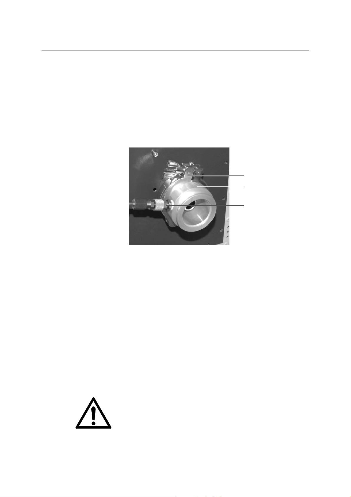
INSTALLATION
Preparation
1. Equ ip the purge gas line with a quick-acting connector.
Connecting the Beam Guidance System
2. Con nect the purge gas connection tube (see Figu re 21, B) with the
connection flange on the laser device’s right-hand side using the
provided clamping ring (A).
A
B
C
Figure 21: Purge gas connection tube for beam guidance system
3. Connect the beam guidance system with the purge gas conn ection
tube using the second clamping ring.
4. Connect the purge gas line (see Figure 21, C) with the purge gas
connection tube.
Finalization
5. Evacuate the beam path shielding and, where fitted, refill with
purge gas to prepare starting laser operation (see Section 7.2 on
page 90).
5.11 New Gas Fill
CAUTION
Risk of damaging the laser tube!
For transportation, the laser tube is filled with helium at a pressure of
1500 mbar. Never attempt to start laser operation with this filling!
Always perform a new gas fill before starting laser operation (see
Section 8.5 on page 116).
78 User Manual OPTex
Page 89

6 LASER CONTROL
This chapter describes the laser control software simulated on an PC
(PC Controller).
The information in this chapter is not sufficient to enable you to fully
perform the operation and maintenance procedures initiated through
the respective software commands. These procedures are described
in the operating and servicing sections of this manual (see Chapters 7
and 8).
6.1 Laser Control Software
NOTE
To enable control through a PC, the laser control software WINLAC
(provided on floppy disk) has to be installed on a PC complying with
the specifications in Section 4.5. The necessary connections and the
software installation proce dure are described in Chapter 5.
Laser Control Software
6.1.1 Start Laser Control Software
A0507OPTex
Select the program group WINLAC and double click the WINLAC icon.
The laser control screen shown in Figure 22 appears.
Figure 22: Laser control screen
LAMBDA PHYSIK - 07/2005 79
Page 90

LASER CONTROL
C
6.1.2 Exit Laser Control Software
To terminate the laser control software, click EXIT on the WINLAC
screen. Only on this way the laser control files are updated.
6.1.3 Laser Control Screen
The laser control screen consists of various buttons, lamps, counters
and displays.
The purpose of the buttons is described in Section 6.1.3.1.
The purpose of the counters and displays is described in Section
6.1.3.2.
The purpose of the lamps is described in Section 6.1.3.3.
6.1.3.1 Buttons
All buttons that can be selected at any particular time are highlighted
(black colored). In Figure 23 each button is denoted with a letter or
letter and digit combination. This denotation serves as a cross
reference to the corresponding description in this section.
A B
D
E1
E2
E3
E4
FGHIKLMN
Figure 23: Buttons on laser control screen
80 User Manual OPTex
Page 91

Laser Control Software
A NEW FILL Starts the new gas fill procedure. The existing
gas is pumped out of the laser tube and the
laser tube is filled with fresh gas from a premix
gas cylinder. The valve currently opened is
indicated by the corresponding light on the
screen (see Section 6.1.3.3).
Requirements: LASER OFF
Premix gas cylinder with
sufficient pressure connected
to “PREMIX”
BFLUSHING Opens a new window enabling the gas lines or
laser tube to be flushed:
FLUSH EXT Evacuates the premix gas supply line and
refills with inert gas to enable gas line
maintenance (e.g. exchanging the premix gas
cylinder).
Requirements: LASER OFF,
Inert gas cylinder with sufficient
pressure connected to “INERT”
FLUSH INT Evacuates the laser tube and refills with inert
gas to enable windows exchange with leak
testing.
Following this, a new gas fill is necessary (see
Section 8.5).
Requirements: LASER OFF,
Inert gas cylinder with sufficient
pressure connected to “INERT”
FILL INERT Evacuates the laser tube and refills with inert
gas up to a pressure of 1500 mbar to enable
laser tube transport (transportation fill).
Following this, a new gas fill is necessary (see
Section 8.5) to restart laser operation.
Requirements: LASER OFF,
Inert gas cylinder with sufficient
pressure connected to “INERT”
A0507OPTex
LAMBDA PHYSIK - 07/2005 81
EXIT Closes the window without performing a gas
action.
CQUIT Aborts gas actions.
D EXIT Term in ate s th e lase r cont ro l progr am .
Requirements: LASER OFF
Page 92

LASER CONTROL
E1 Large HV
increment
Increases the high voltage setting by 10 %.
Requirements: READY lamp on,
Laser in HV Const. mode
E2 Small HV
increment
Increases the high voltage setting by 1 %.
Requirements: READY lamp on,
Laser in HV Const. mode
E3 Small HV
decrement
Decreases the high voltage setting by 1 %.
Requirements: READY lamp on,
Laser in HV Const. mode
E4 Large HV
decrement
Decreases the high voltage setting by 10 %.
Requirements: READY lamp on,
Laser in HV Const. mode
F CONTROL Toggles between the high voltage constant
mode (HV CONST) and the energy constant
mode (EGY CONST). When the energy
constant mode is active, the red lamp next to
the CONTROL button is on.
Requirements: READY lamp on
NOTE
The EGY Const mode is only available with
energy monitor!
G LASER OFF Switches off the HV power supply to disable
laser operation. All currently active laser
operations (e.g. BURST or REPETITION) are
immediately aborted and the repetition rate and
quantity are reset.
A corresponding signal can be sent by pressing
the space bar on the PCs keyboard.
Requirements: LASER ON,
Laser operates (REPETITION
ON, BURST or EXT. TRIGGER
active)
HOFF Interrupts the laser operation (REPETITION
ON, BURST or EXT. TRIGGER) by switching
off the HV power supply. The repetition rate
and quantity are not reset.
Laser operation can be continued by starting
any operation mode.
Requirements: LASER ON,
Laser operates (REPETITION
ON, BURST or EXT. TRIGGER
active)
82 User Manual OPTex
Page 93

Laser Control Software
I WATCHCOUNT Activates the high voltage and starts laser
operation in accordance with signals received
from an external trigger generator for a
internally or externally given number of pulses.
Laser operation cannot be stopped by all
software interrupts!
Requirements: READY lamp on,
LASER ON,
External trigger generator
connected and correctly set,
QUANTITY (number of pulses)
set
K EXT-TRIGGER Activates the high voltage and starts laser
operation in accordance with the signals
received from an external trigger generator. A
laser pulse is emitted whenever a trigger pulse
is received.
Requirements: READY lamp on,
LASER ON,
External trigger generator
connected and correctly set
L BURST Activates the high voltage and starts laser
operation at the preset repetition rate for the
preset number (quantity) of pulses.
Requirements: READY lamp on,
LASER ON,
REPET RATE and QUANTITY
values set
M REPETITION ON Activates the high voltage and starts laser
operation at the preset repetition rate.
Requirements: READY lamp on,
LASER ON,
REPET RATE value set
N LASER ON Enables laser op eration. The HV power supply
receives current but the storage capacitors are
not charged and no laser pulses are emitted.
For emission of laser beam pulses, select an
operation mode after running a security period
of 5 seconds (REPETITION ON, BURST, EXT
TRIGGER or WATCHCOUNT).
Requirements: READY lamp on
A0507OPTex
LAMBDA PHYSIK - 07/2005 83
Page 94

LASER CONTROL
6.1.3.2 Counters and Displays
There are three counters and four disp lay s on th e las er cont ro l scre en
(Figure 24). Clicking a counter when the laser is online opens a
subsequent menu enabling a new value to be entered.
A BC
D
Figure 24: Counters and displays on laser control screen
EFG
AWARMUP Percentage indicator indicating the proceeding
of the thyratron warm-up period. The warm-up
is additionally indicated by the red lamp left
from the indicator.
B PRESSURE Graphical and numerical display indicating the
current gas pressure in the laser tube. If the
pressure is sufficient for laser operations, the
graphical display is blue. If there is insufficient
pressure, the graphical display turns red. If
there is an overpressure, the graphical display
turns yellow.
CENERGY VALUECounter indicating the current pulse energy for
laser operations in the EGY Const. mode.
D REPET. RATE Counter indicating the current repetition rate for
internally triggered laser operations.
E QUANTITY Counter indicating the current amount of laser
pulses to be generated in Burst or internally set
Watchcount mode.
84 User Manual OPTex
Page 95

F Counters During laser operation, the number (quantity)
GHIGH VOLTAGEGraphical and numerical display indicating the
6.1.3.3 Lights
In Figure 25 each light is denoted with a letter or letter and digit
combination. This denotation serves as a cross reference to the
corresponding description in this section.
Laser Control Software
of pulses are displayed as burst counter
(counts down) and user counter (counts up).
current high voltage level within the tuning
range (in percent) for operations in the HV
Const. mode.
A BC D
T
S
R
P
O
N
M
L
L1
L2
L3
I2 I3 I4 I5 I6 I7 I8
I1K
Figure 25: Lights on laser control screen
NOTE
The error field (errors I to L) will automatically be opened if an error
occurs.
E
F
G
H
I
A0507OPTex
LAMBDA PHYSIK - 07/2005 85
AVAC The vacuum valve is open and the vacuum
pump has been actuated (see gasflow diagram
in Figure 62 on page 155).
BLH Laser tube gas valve is open.
Page 96

LASER CONTROL
CPRE The premix gas valve (gas inlet) is open.
DINERT The inert gas valve (gas inle t) is open.
ETEMP Warning light for exceeding tube temperature
(gas reservoir, more than 48 °C).
FREADY The laser device is ready for operation. High
voltage can be switched on.
G CONTROL The laser is operating in the energy constant
(EGY Const.) mode.
NOTE
The EGY Const mode is only available with
energy monitor!
H PEM ERROR Fault in the energy monitoring system. The
error message vanishes by clicking on the
lamp when the cause of the error has been
rectified. As long as the error remains, the EGY
Const. mode cannot be selected.
I OPERATION
ERROR
Flashes red to indicate an error preventing
laser operation. After rectifying the error the
laser device has to be switched off and then on
again before laser operation can be restarted.
To ease troubleshooting, one or more of the
lights below OPERATION ERROR (I1 to I8) are
also red.
I1 PRESSURE Gas pressure in the laser tube is out of the
operating range. This indicates a leak or a
defective valve or pressure sensor.
I2 FILL Fault in the gas supply line: evacuating or filling
time exceeded (time out error).
I3 HV CHARGING Discharge capacitor’s charging time exceeded.
I4 OVER-
TEMPERATURE
Warning light for exceeding temperature (tube
outside, more than 60 °C).
I5 CPU CPU or communication failed.
I6 HV SUPPLY The temperature of the HV power supply unit is
too high, the fuse is blown off or the line voltage
is too low.
I7 HV
Overvoltage in the HV power supply circuit.
OVERVOLTAGE
I8 THYRATRON The thyratron is not receiving power or heating
circuit failed.
K EEPROM The lamp flashes if the memory check failed.
Laser operating data and status information
are saved on the EEPROM approx. every two
minutes.
86 User Manual OPTex
Page 97

Laser Control Software
L STATICAL
ERROR
Flashes red to indicate an error interrupting
laser operation. Laser operation is
automatically restarted when the cause of the
error has been rectified. To ease
troubleshooting, one or more of the lights
below STATICAL ERROR (L1 to L3) are also
red.
L1 INTERLOCK External safety interlock (remote circuit) is
open.
L2 LASERHEAD
CHAMB.
L3 ELECTRONIC
CHAMB.
The right-hand, left-hand or top service panel is
open or the tube temperature is too high.
The front panel is open or the electronics
chamber temperature is too high.
M WATCHCOUNT The storage capacitors are supplied with high
voltage and the laser is operating with external
triggering for a predefined number of pulses in
a non-interruptable mode.
N EXT-TRIGGER The storage capacitors are supplied with high
voltage and the laser is operating with external
triggering. The amount and frequency of pulses
are determined by the external trigger
generator.
A0507OPTex
O BURST The storage capacitors are supplied with high
voltage and the laser is operating with internal
triggering for a predefined number of pulses.
P REPETITION ON The storage capacitors are supplied with high
voltage and the laser is operating with internal
triggering for an indefinite number of pulses.
R LASER ON Power is applied to the HV power supply unit.
Laser operation can be started.
S WARM UP The laser device is in the warm-up phase or
laser tube flushing (FLUSHING INT) is in
progress. An indicator to the right of the lamp
displays the warm up percentage (see Figure
24 on page 84)
T Gas mode Indicates that gas actions being performed.
LAMBDA PHYSIK - 07/2005 87
Page 98

LASER CONTROL
6.2 Service Software
To ease service operations and troubleshooting, the service software
LASTEST (only available for service personnel) can be installed on the
external controller. This service software provides additional functions:
The screen for error messages is continuously displayed.
A test mode can be started to check laser functions. In the test mode,
the warm-up period can be aborted and gas actions can be canceled.
The gas valve assay can be controlled directly.
The communication between PC and laser device as well as between
PC and DLL can be checked.
The data transfer can be interrupted without error message.
6.3 Logbook file
For documentation and diagnosis, a logbook file (“eximer.log”)
containing Excel-readable entries is created in the directory “Excimer”
by the DLL interface.
Every laser status change is recorded in this logbook file. Under
normal operating conditions without status changes the status of the
laser device is continuously recorded all 30 minutes. Error codes are
noted by date and time and entered together with the laser status.
If the file size reaches 1.4 MB, a new file will be created. We
recommend to erase old versions of the logbook file periodically to
ensure adequate free memory on the hard disk of the laser controller.
88 User Manual OPTex
Page 99

7 OPERATION
This chapter describes the operation of the OPTex.
NOTE
A) Before attempting to operate the OPTex, familiarize yourself with
the layout and operation of the laser control interface, as described in
Section 6.1 on page 79 ff.
B) Prepare a laser logbook to keep a continuous record of data
relating to laser operation. This simplifies routine maintenance
scheduling as well as problem location.
Unless otherwise stated, the descriptions in this section assume that
the OPTex is PC controlled.
To ease understanding the information in this section, keep in mind the
difference between laser device and laser (see Section 2.2 on page
12).
Check Beam Path
7.1 Check Beam Path
A0507OPTex
Purpose
Ensure that the laser beam will be safely guided to the intended target.
WARNING
Risk of serious injury through laser radiation!
Ensure that there are no reflective objects or particles in the path
of the laser beam to avoid uncontrolled direct or diffuse
reflection of the laser beam.
CAUTION
Risk of fire or release of fumes!
Ensure that there are no materials in the path of the laser beam which
may ignite or emit fumes when subject to laser radiation.
NOTE
Utmost safety is provided by completely shielding the beam path (e.g.
through a protective enclosure or protective tubes). When the beam
path is not to be shielded, keep the beam, wherever possible, in a
single plane. Avoid directing the beam at head height.
Tools and Materials
None
•
LAMBDA PHYSIK - 07/2005 89
Page 100

OPERATION
Checking the Beam Path
1. Shielded beam path:
Ensure that all shields are correctly installed, i.e. there is no risk of
unwanted beam emission.
2. Unshie lded beam path:
Ensure that there are no persons, reflective objects or objects in the
beam path which can reflect the laser beam, ignite and/or emit
fumes.
3. Secur e the beam path and vicinity of the beam path against entry
of persons.
7.2 Start-Up Laser Device
This chapter describes the procedures required to start-up the OPTex
laser device.
7.2.1 Turn On Gas Supply
Purpose
Turn on the excimer laser gases and, where fitted, the purge gas for
the beam guidance system to enable laser operation.
WARNING
Health hazard through halogen gas leakage!
To minimize the risk of gas leaks, keep the gas cylinder valves
closed except when running the laser in the energy constant
mode (EGY Const.) or when performing a new gas fill.
NOTE
The purge gas for the beam guidance system is to be turned on at
least 5 minutes before starting laser operation.
Tools and Materials
Gas cylinders with gases as specified in Section 4.7 on pa ge 59 and
•
with a remaining pressure of at least 5 bar (abs.)
Preconditions
Gas cylinders for the respective laser gases connected to the
•
corresponding connections on the laser device
Gas cylinder valves closed
•
90 User Manual OPTex
 Loading...