

Lamar Technologies D-50 User Manual
OPERATING MANUAL
BETA D-50
BATTERY TESTER / ANALYZER
Lamar Technologies, 14900 40th Ave NE, Marysville WA 98271
Tel: (360) 651-8869 • Fax: (360) 651-6677
www.lamartech.com/powerpr od uct s

TABLE OF CONTENTS
1. SYSTEM OVERVIEW ... ......................................................................
.1
2. INSTALLATION ... .................................................................................. .4
3. QUICK OPERATING GUIDE ... ......................................................
4. DETAILED OPERATING INSTRUCTIONS ... ................................ …
5. CALIBRATION AND MAINTENANCE ... ..........................................
6. TROUBLE-SHOOTING ... ..............................................................
7. SPECIFICATIONS ... .........................................................................
APPENDIX A - BATTERY OVERVIEW ... ...........................................
WARRANTY ... ......................................................................................... ..
CERTIFICATION OF CALIBRATION .………………………………….
BETA D-50 TESTER / ANALYZER - OPERATING MANUAL V 2.2
…..6
.9
..18
…27
..29
....30
..32
...33

1. SYSTEM OVERVIEW
1. SYSTEM OVERVIEW
1.1 SYSTEM OVERVIEW
The Beta D-50 Tester/Analyzer is a self cont ained unit for d ischarge capacity test ing of
rechargeable batteries. It has been designed to accurately test and guarantee the
emergency capacity of sealed or vented lead-acid or nicke l-cadmiu m batteries.
Guaranteed emergency capacity is especially impor tant for air craft batteries.
The Beta D-50 enables testing of a battery's capacity by loading it w ith a const ant
current of max 50 amperes (usually set to 80-100% of the ba ttery's ca pacity rating)
during a fixed period of time (usually 60 minutes). The D-50 analy zes the discharge
characteristics and passes or fails the bat tery depend ing on the ba ttery’s ab ility to
maintain a specified minimum voltage (cu toff voltage) for th e duration of the test. The
unit has pass/fail indicators as well as displays for discharge current, cutoff voltage,
battery voltage, and test time.
The flexibility of test parameters of the Beta D-50 makes it usable for a wide variety of
batteries and voltages. The unit accurately tests lead-acid batteries of 12 or 24 volts, as
well as nickel-cadmium batteries up to 24 volts.
The use of solid state circuits in the Beta D-50 h as kept its weight to a mere 30 lbs. (14
kg). Consequently the unit is easy to move around to accommodate flexibility in the work
environment.
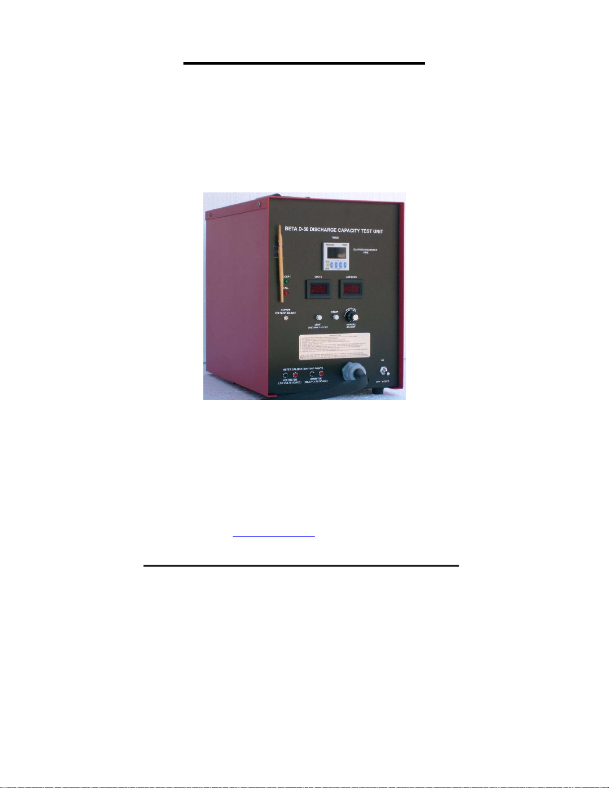
1.2 DISPLAYS AND CONTROLS
The Beta D-50 has been designed to have very sim ple and easy to un derstan d controls
and displays (see figure 1-1 and 1-2).
BETA D-50 TESTER / ANALYZER - OPERATING MANUAL V2.2
Page 1

1. SYSTEM OVERVIEW
ACCEPT LAMP
INDICATOR
Illuminates at end of
test when timer has
completed its preset
time
FAIL LA M P
INDICATOR
Illuminates when
voltage has
dropped to cutoff
before the timer
times out
CUTOFF
VOLTAGE
ADJUST
TRIMPOT
Adjusts cutoff
voltage
CUTOFF VOLTAGE
VIEW BUTTON
Pressed before or
during test to display
and adjust cutoff
voltage
Page 2
DIGITAL
VOLTMETER
Displays 1) battery
voltage during
discharge; or 2)
cutoff voltage
DIGITAL
DISCHARGE TIMER
Displays elapsed
discharge time. Can be
set with push buttons
CALIBRATION
START BUTTON
Pressed to start test
INSTRUCTION
PANEL
TEST PORTS
Provides output for %$ 77(5 <
voltmeter and ',6&+ $ 5 * (
ammeter calibration &$%/(
Figure 1-1. Front view of Beta D-50
BETA D-50 TESTER / ANALYZER - OPERATING MANUAL V2.2
DIGITAL
AMMETER
Displays
discharge
current.
AMPERE
ADJUST KNOB
Sets discharge
current
AC ON-OFF/
RESET SWITCH
Turns unit on or
off and resets all
indicators and
functions
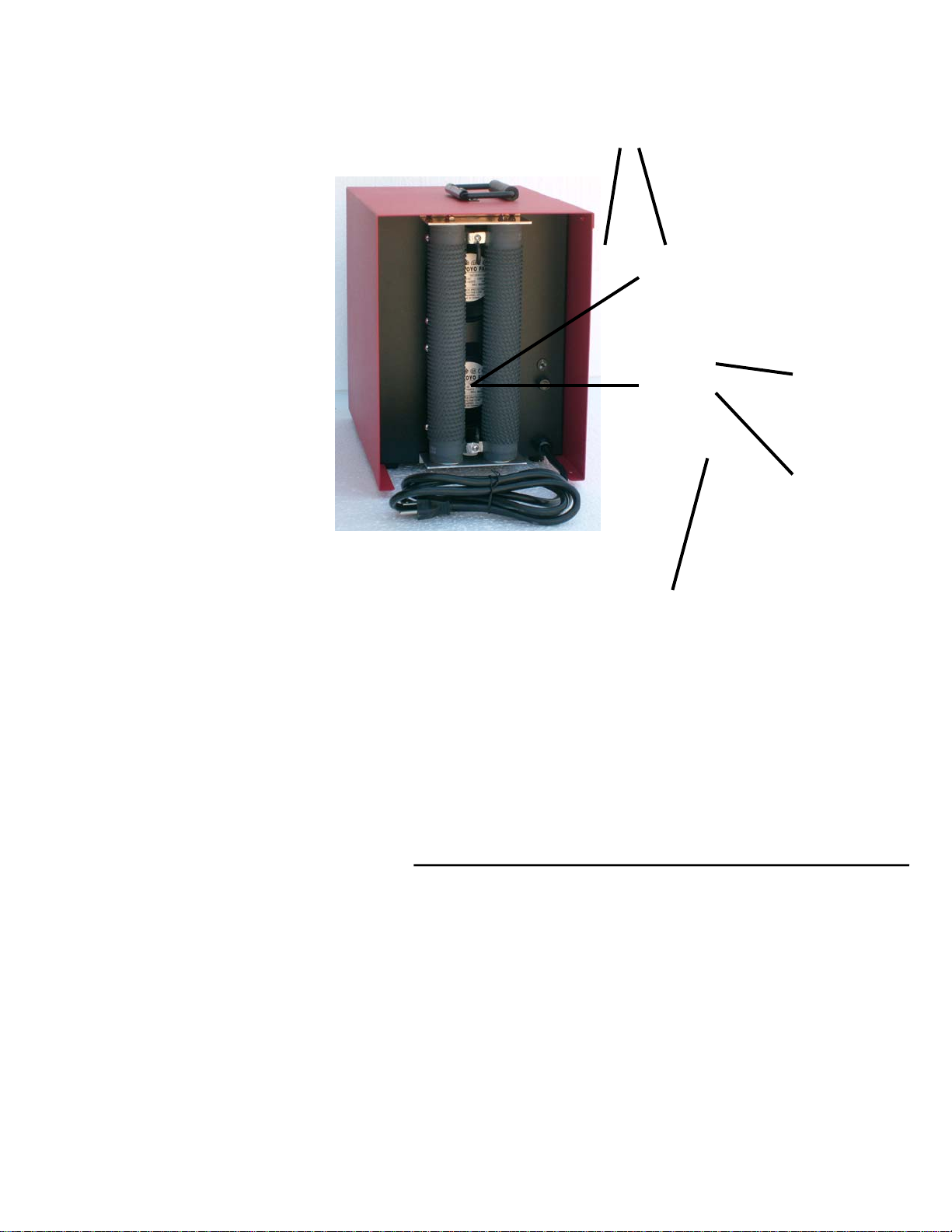
1. SYSTEM OVERVIEW
DISCHARGE
RESISTORS
AC VOLTAGE
SELECT DIAL
COOLING
FANS
Selects mains input
voltage (115 or 230
volts)
AC LINE FUSE
protects line and
equipment
AC MAINS
CABLE
Figure 1-2. Rear view of Beta D-50
BETA D-50 TESTER / ANALYZER - OPERATING MANUAL V2.2
Page 3

2. INSTALLATION
2. INSTALLATION
2.1 LINE VOLTAGE
The Beta D-50 can operate on either 115 or 230 Volts AC. The desired line voltage can
be selected on the rear of the unit.
CAUTION: Ensure that the unit is set for the appropriate line voltage before operation.
A. On the back of the unit locate the AC voltage select dia l.
B. Set dial for appropriately marked AC voltage (115 or 230 volts) using a screwd rive r.
C. For 230 VAC operation, the 115 VAC plug must be replaced w ith one for 230 V AC in
required configuration.
NOTE: If the plug has to be changed make sure to connect the green AC line wire to
ground.
Connect the unit to a wall outlet with at least a 10 ampere ca pacity. Shar ing of the line
with other equipment may result in erratic operat ion if other equipment draws hig h pulse
or surge currents.
NOTE: The Beta D-50 will maintain its operational integrity with line fluctuation less than
± 10%.
2.2 TERMINALS
Two important points about the DC battery cable and connector are:
A. If the aircraft battery quick disconnect connector is removed, the
ring terminals can be used to connect to a post terminal battery.
B. If the cable is extended or repaired during maintenance, the
sensing leads which run with the heavy DC cable mu st be
connected to the new terminal (see se ction 5.5).
Page 4
WARNING : Correct polarity must be observed.
BETA D-50 TESTER / ANALYZER - OPERATING MANUAL V2.2

2. INSTALLATION
2.3 SPACE REQUIREMENTS
The Beta D-50 system occupies 15" x 10 ¼" (381 mm x 260 mm) of table top space.
Place the unit on a sturdy workbench in a well-ventilated battery servicing area with the
battery adjacent to it.
The rear of the unit has air flow fr om h ot re sistors. Allow a t le ast 6" (150 mm) of
separation from the wall and adjacent equipment in or der to ma intain proper a ir flow.
WARNING: Due to the air flow from hot resistors on the
rear of the unit, use extreme caution on placement.
NOTE: In non air-conditioned rooms it is recommended
that circulating or extracting fans be used to aid in the
removal of heated air.
NOTE: Operation in dusty or otherwise dirty air
environments will severely reduce the cooling capacity of the
fans and can lead to premature failure.
BETA D-50 TESTER / ANALYZER - OPERATING MANUAL V2.2
Page 5

3. QUICK OPERATING GUIDE
3. QUICK OPERATING GUIDE
This section gives an overview of how to quickly get started capacity discharge testing a
battery using your Beta D-50. If there is uncertainty at any point on how to proceed, please
refer to the more detailed instructions in the section 4.
A.
Turn off the AC on-off/reset power switch.
B.
Repeatedly turn the Ampere Adjust knob fully
counter-clockwise to set discharge current to zero.
WARNING: Always turn the AC power switch off before
connecting or disconnecting a battery
NOTE: Once set, all settings are maintained and need not be
reset for duplicate testing
SWITCH OFF MAINS POWER
TURN DOWN DISCHARGE CURR
ENT
C.
CONNECT BATTERY
Connect the battery DC cable to the battery and ensure the
connector is plugged in completely.
SWITCH ON MAINS POWER
D.
Turn on the AC on-off/reset power switch. An audible alarm
sounds, and the Accept lamp illuminates. Meters read all
6's or 8's.
E.
SET TIMER
Set the timer by pushing buttons up or down to the
required discharge time (usually 60 minutes)
Page 6
BETA D-50 TESTER / ANALYZER - OPERATING MANUAL V2.2

3. QUICK OPERATING GUIDE
F. VIEW AND SET CUTOFF VOLTAGE
a. Press and hold the View Voltage Cutoff button. The set cutoff voltage
is shown on the voltm et e r d is p lay.
b. Use a 1/16 inch (2 mm) slot b lade pr ecisio n
type screw driver to adjust the cutoff voltage
to the desired level.
G.
PUSH START BUTTON
The audible alarm stops. The voltmeter displays the battery
voltage, the ammeter reads 0 and the timer starts. The red
LED on the timer illuminates. “OP” on the timer illuminates
and the red LED flashes.
H.
SET DISCHARGE CURRENT
Slowly turn the multi-turn Ampere Adju st knob clo ckwise t o
the desired discharge current. The ammeter displays the
current as it is being adjusted.
I. WAIT FOR THE DISCHARGE TEST TO
AUTOMATICALLY COMPLETE
During the test the battery voltage, discharge current, and
elapsed discharge time are displayed. The voltage wi ll
continuously decrease while the cur rent remain s constant. The
test completes when either the set discharge t ime or the low
cutoff voltage has been reached. An audible a larm sounds and
the displays freeze at their final values.
J. 1. IF TEST PASSED
The green Accept lamp illuminates. This ind icates the discharge
has continued through the duration of the set discharge t ime (the
red LED and “OP” on timer is off.) without the cutoff voltage bein g
reached. The battery is usually fit for serv ice, af ter co mplet e
recharge. See below under respective battery type.
BETA D-50 TESTER / ANALYZER - OPERATING MANUAL V2.2
Page 7

2. IF TEST FAILED
The Fail lamp illuminates if the discharge has
been discontinued because the cutoff voltage has been reached before
the completion of th e set discharge time. The red LED goes out. The
time is frozen at the elapsed time at which the test failed. The battery is
in need of reconditioning or must be rejected for
aircraft service. Refer to the battery manufacturer's maintenance
manual on how to proceed.
K.
SWITCH AC POWER OFF
Switch the AC on-off/reset switch off before r e m ov in g he ba t t er y .
NOTE: If in emergency it is required to stop the test, switch the un it to
off/reset. When the test is restarted the timer is rese t to ze ro. I t may be
necessary to recharge the battery before resuming the test.
Page 8
BETA D-50 TESTER / ANALYZER - OPERATING MANUAL V2.2

4. DETAILED OPERATING INSTRUCTIONS
4. DETAILED OPERATING INSTRUCTIONS
4.1 DISCHARGE CHARACTERISTICS
The lead-acid and the nickel-cadmium cells are gener ally assigne d nominal op en circu it
voltages of 2.10 volts and 1.35 volt s respective ly. Actu al open circu it voltage at 75°F/ 25°C
for a fully charged battery cell depends on stat e-of-charge and time afte r charge.
During discharge, the voltage of the cell or battery immediately begins to decrease
because of the effective internal resistance of the cell. This includes the resistance of
the terminal posts, active material, plate lugs and grids, separator s, and cont act
resistance between the surface of the active material and the electrolyte. The in ternal
resistance increases during discharge, being greater toward the end of discharge, when
the terminal voltage is lower.
As voltage gradually becomes lower during d ischarge, the point o f near exhaustion is
reached. At this point, the discharge volt age curve b egins to drop very sharp ly to a value
which is of no further practical use. Usua lly this happ ens at 18-20 volts for a 24 vo lt leadacid battery and 1 volt per cell for a nickel- cadmium b attery (see f igure 4-1).
Battery manufacturers specify a cutoff voltage which the battery must exceed during a
discharge test to have acceptable capacity. The cutoff voltage varies with the rate of
discharge (the discharge current/time combination used to draw the same capacity). For
example, the minimum cutoff voltages for a 30 ampere-hour, 24-volt naval aircraft leadacid storage battery are generally specified as is sho wn in table 4-1.
The specified final minimum cutoff voltage repre sents the va lue of voltag e at which the
rated ampere-hour capacity of the battery must have been de livered for the specif ied
discharge rate. Figure 4-1 is a typical discharge cur ve for a 40 a mpere-hour sealed
lead-acid (SLAB) aircraft storage battery discharged at a 1-h our rate of 40 amperes.
From figure 4-1, it is observed that at the end of 1 hour of disch arge time , the battery
voltage has reduced only to about 22 volt s. Becau se the m inimum required cu toff
voltage is 18 volts at the 1-hour discharge rate, the ba ttery exceeds the minimum
requirements. With increasing hours of use or age, the batt ery capacity decreases.
Therefore, battery manufacturers usually recommend testing for a capacity equal to
80% of the original ampere-hour rating.
Rate of Discharge Minimum
Discharge Current Cutoff Voltage
5 hours 6 amperes 21.0 volts
2 hours 15 amperes 19.2 volts
1 hour 30 amperes 18.0 volts
Table 4-1. Cutoff voltages at different discharge rates for a
30 ampere-hour, 24 volt lead-acid battery
BETA D-50 TESTER / ANALYZER - OPERATING MANUAL V2.2
Page 9
 Loading...