


INSTRUCTION MANUAL
ACTIVATOR 282
BATTERY CHARGER
FOR 24 VOLT AIRCRAFT AND MILITARY BATTERIES P/N ACTIVATOR 282 (also called 282-300)
Serial numbers 21228 and higher, manufactured January 2009 and later.
Issued By: Power Products
Inc. / Lamar Technologies LLC
14900 40th Ave. N.E.
Marysville, WA 98271
Tel: 360-651-8869 Fax: 360-651-6677
www.power-products.com or
www.lamartech.com/powerproducts
Table of Contents
CHAPTER |
TITLE |
PAGE NO. |
FIG. 1 |
Photo with Callouts |
2 |
FIG. 2 |
Dimensions |
3 |
0.1 |
Quick Instructions |
4 |
1.0 |
Introduction |
5 |
2.0 |
Charging |
6 |
3.0 |
General Operation |
7 |
4.0 |
Battery Charging Protection |
8 |
5.0 |
Nickel Cadmium Topping |
9 |
6.0 |
Calibration Verification |
9 |
7.0 |
Maintenance |
15 |
8.0 |
Troubleshooting |
16 |
9.0 |
Specifications |
17 |
|
Certification of Factory Calibration |
18 |
|
Warranty |
19 |
1
ACTIVATOR 282
BATTERY CHARGER
FOR 24 VOLT AIRCRAFT AND MILITARY BATTERIES P/N ACTIVATOR 282 (also called 282-300)
|
|
|
8 |
|
|
11 |
4 |
|
|
2 |
|
|
|
|
|
|
|
1
 9
9
5
6 
 3
3
7
 10
10
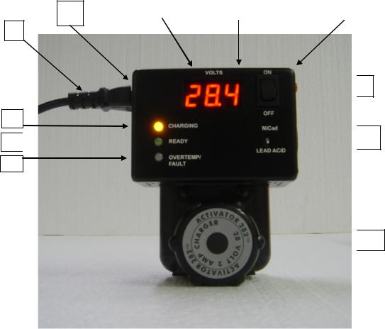
FIG. 1
ITEM NO. DESCRIPTION
1.AC LINE CORD
2.ON/OFF SWITCH
3.LEAD ACIDNICAD SETTING
4.DIGITAL VOLTMETER, LED
5.LED: CHARGE (YELLOW)
6.LED: READY (GREEN)
7.LED: OVERTEMP/FAULT (RED)
8.COOLING FAN
9.TEST POINTS (FOR EXTERNAL VOLTMETER)
10.BATTERY QUICK DISCONNECT KNOB
11.INSTRUCTIONS & RATING PLATE
2

DIMENSIONS
4.5 |
|
3.5 |
|
||
|
|
|
5.75
FIG. 2
3
Activator Outline
ACTIVATOR 282
BATTERY CHARGER FOR 24 VOLT AIRCRAFT AND MILITARY BATTERIES
0.1QUICK INSTRUCTIONS
CAUTION: Read the complete instructions before use. These quick instructions are for reference only.
A.Set switch of ‘Off’: Select Lead Acid or NiCad.
B.Plug in AC line, 90-240V 50/60/400 Hz. Connect Activator to battery via Quick-Connect knob.
C.Switch to on. Digital Voltmeter reads charge voltage.
CHARGING LED on. Voltage begins to rise.
If battery voltage is below ~ 10V, OVERTEMP/FAULT LED will pulse. As battery voltages raises, OVERTEMP/FAULT LED will remain steady.
D.When the battery is charged, yellow CHARGING LED is off, READY LED on.
E.After 10 hours of charging, if the battery voltage remains under 28 Volts and voltage does not continue to rise (even very slowly), or if the voltage lowers instead of rising, the OVERTEMP/FAULT LED will blink and charge will cut off. This may be a battery fault or the battery requires more time to charge. Reset rocker switch to ‘Off’ then back to ‘On’ for further charge. If this requires many reset cycles, battery may not be accepting charge.
F.If battery overheats, charge cuts off and OVERTEMP/FAULT LED is on.
4
1.0INTRODUCTION
The Activator 282 is a self contained charger for 24 Volt batteries, using the standard MS 3509 Style “Quick Disconnect” pin terminations. This connector is found on most 24 Volt aircraft and military batteries, Sealed Lead Acid Batteries (SLAB), vented Lead Acid (VLRA), and Nickel Cadmium batteries.
Refer to NAVAIR17-15 BAD-1 Manual “Naval Aircraft and Naval Aircraft Support Equipment Storage Batteries” for military aircraft batteries, and to the battery manufacturers’ instruction manuals for commercial aircraft batteries. The Activator 282 charging methods conform to the BAD-1 Manual wherever possible within the ratings of the Activator 282, as well as to the commercial requirements.
Although very compact and lightweight, the Activator 282 is a complete charger and not a trickle charger. It also maintains a battery over an extended time period of days, weeks, or months by fully charging, shutting off, and then continuously recycling as the battery self-discharges and requires recharge. This method of maintenance extends the life of the battery as opposed to a constant trickle, which causes some gassing, heat, and loss of the electrolyte.
1.1CONNECTION TO BATTERY
The charger electronics are built into a mating Quick Disconnect housing and plugs directly into the battery. Therefore, no charge cables are required and correct polarity is assured.
WARNING: Do not connect any charge cables to the Activator and a battery without the Quick Disconnect pins unless it is certain that polarity is correct. Reversed polarity will blow an internal fuse and may damage the Activator.
1.2AC LINE CONNECTION
5
 Loading...