

LAKOS FTS User Manual

225
102
325
147
600
272
LS-647c (Rev. 5/12)
234
658
559
931
298
422
FTS SERIES SAND FILTERS
INSTALLATION & OPERATING MANUAL
LAKOS FTS Series Sand Filters are specifically intended for use in full-stream or
side-stream applications. For side-stream, we recommend the industry
standards of 10% to 20% of full-stream flow. However, you are free to operate at
higher or lower percentages, based on your specific application conditions and
criteria. Side-stream may be applied by tapping from a mainstream line or by
tapping the basin/remote sump to achieve a given turnover rate.
LAKOS does not recommend the FTS Series for basin/remote sump sweeping
applications. The proper use of this technique requires a specific sweeping
design involving HydroBoosters and the proper flow/pressure to ensure
performance. More specifically, LAKOS recommends the LAKOS TC Series for
basin/remote sump sweeping, featuring LAKOS Sand Separators. This
equipment is simply better suited for applications where settleable solids are
involved.
Maximum operating pressure for a LAKOS FTS System is 50 psi (3.4 bar). Do
not install this system into applications with higher pressures.
DELIVERY INSPECTION
• Immediately inspect the system upon arrival for any damage that may have occurred
during shipping. Look for crate damage, pierced or torn boxes or any other signs of
handling, which may suggest damage to the system. Shipping damage must be
reported to the carrier for direct handling. LAKOS is not responsible for shipping
damage.
• LAKOS FTS Series Systems are shipped with all major components assembled onto
the skid. Selected small items, such as the pressure gauges, may be removed and
inserted in the controller box for shipping.
• LAKOS sand media is shipped separately in 100 lb. (45 kg) bags. The exact number
of bags is determined by the actual system size (see chart below). Do not introduce
media sand into the FTS System until the system is placed in its operating position.
MODEL MEDIA SAND REQUIREMENT OPERATING WEIGHT
LBS KG LBS KG
FTS-20-045 200 90
FTS-24-065 250 113
FTS-30-100 400 181

INSTALLATION PROCEDURES
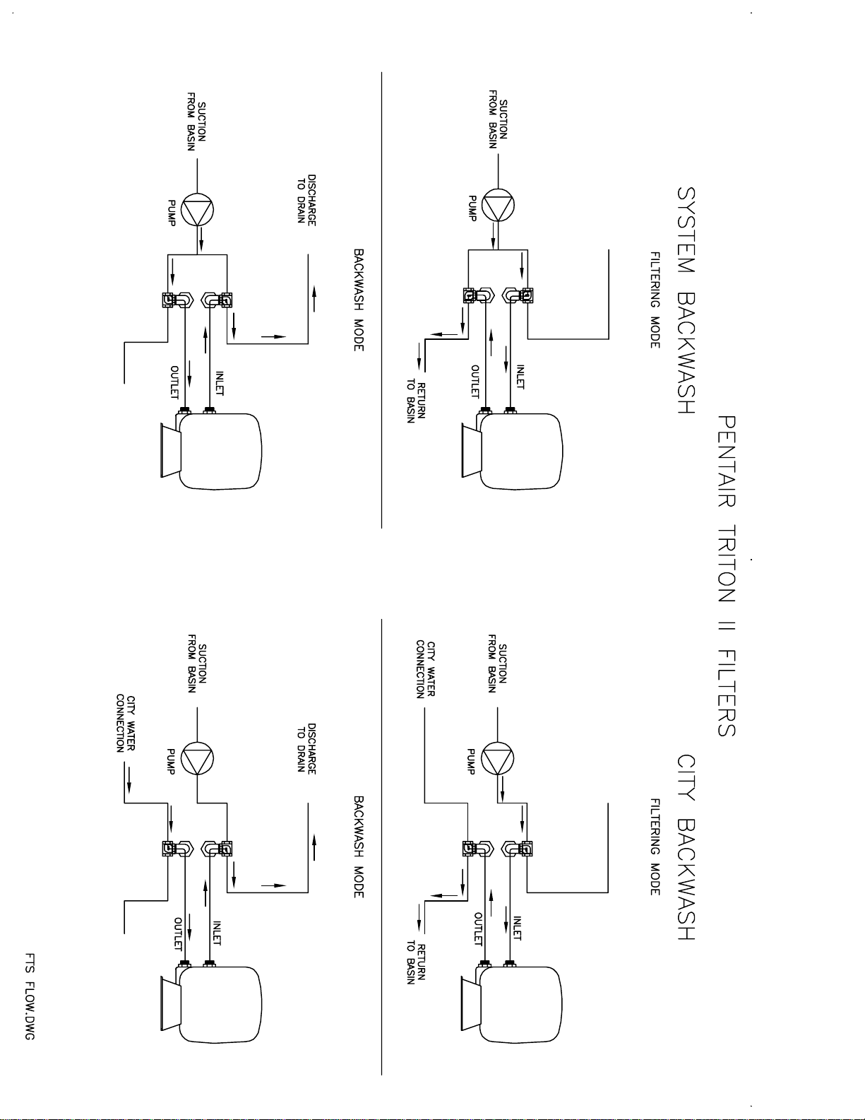
See installation piping
diagram on page 4.
1. A suitable foundation or pad must be provided to support the full operating weight of
the FTS System, including liquid. See chart on page 1. Anchor the unit to the
foundation to prevent vibration and/or movement.
2. Use caution when moving the FTS System into position. Forklift only by the skid. If
hoisting is necessary, do not attach hooks or straps to the inlet piping/manifold.
3. FTS System requires a flooded pump suction to ensure proper pump operation.
4. Electrical connection to the FTS System’s controller (automatic systems only) or
pump (manual systems only) should be made in accordance with all applicable
codes and electrical standards.
5. Piping connections to and from the FTS System should be of at least the same pipe
size as the FTS inlet and outlet connections. Do not install sm
anywhere on the inlet, outlet or backwash lines. Check local codes to determine if
appropriate backflow prevention is necessary at the inlet.
6. A service valve is recommended on both the inlet and outlet pipes in order to isolate
the FTS System for servicing when necessary.
7. If FTS System
Connect piping to the appropriate backwash connection (see installation
illustrations).
8. Backwash connection piping is not supplied by LAKOS and must be provided onsite. Do not reduce the line size any smaller than the backwash outlet pipe size.
Check local codes to determine if appropriate backflow prevention is necessary on
the backwash line. Install a backwash throttling valve on the backwash line to control
backwash flow. This valve should be a 2-inch gate valve (available as option from
LAKOS).
9. Determine if the drain for the backwash water can handle the necessary backwash
flow (see chart below). If not, provide a suitable backwash reservoir to capture
backwash flow (reservoir available as option from LAKOS).
10. Check the FTS System’s pre-strainer and remove any foreign matter. Close and
secure the strainer cover.
11. If system is to be exposed to sub-freezing conditions, suitable insulation or other
measures should be provided to keep the unit from freezing to prevent water-to-ice
expansion and damage.
will be backwashed from
MODEL MINIMUM BACKWASH FLOW
U.S. gpm m3/hr
FTS-20-045 33 7.4
FTS-24-065 47 10.7
FTS-30-100 74 16.8
a water source other than system
aller diameter pipe
flow –

12. ADDING FILTER SAND: Remove upper tank shell by first loosening the flange bolts
Please refer to the Triton Installation & User's Guide included.
around the center of the tank. To equalize flange stress, loosen bolts alternately
(opposite sides of the tank). Remove all bolts. Carefully lift the upper tank shell
straight up, using care not to damage the cord ring seal around the flange. Inspect
the underdrain to be sure all parts and connections are secure. Fill the sand filter
about one-third to half full with clean water. Then, slowly add the appropriate
amount of sand (see page 1). Spread the sand level within the tank. Clean the
flange surface and ring seal of all sand and dirt. Do not lubricate the ring seal.
Lower the upper tank shell onto the lower shell. Install and tighten flange bolts
alternately (opposite each other), not one after the other in a circular motion. For 20-
inch tank diameter, tighten to 20 ft.-lbs. torque; For 24 & 30-inch tank diameters,
tighten to 30 ft.-lbs. torque. Do not over-torque.
13. Check the controller settings (automatic systems only). Typical settings:
• Pressure differential – Factory pre-set only: 13 psi (0.9 bar) on 20-inch and
24-inch FTS Systems; 16 psi (1.1 bar) on 30-inch FTS Systems.
• Backwash Duration – Typical setting is 3 minutes. May be adjusted after
inspection of backwash flow in order to insure proper cleaning and to
minimize liquid loss.
START-UP PROCEDURES
1. Start the pump and inspect all piping/access connections for leaks. Shutdown to
correct any problems.
2. An automatic air relief valve will vent all air from the system.
3. Check FTS System inlet and outlet pressure gauges (mounted onto the controller
panel). Proper operating parameters will result in an inlet pressure of approximately
20-27 psi (1.4-1.9 bar) above the system flow pressure to the FTS System and an
outlet pressure of 13-24 psi (0.9-1.7 bar) above the system flow pressure to the FTS
System. NOTE: If pressure gauges read higher
such as a closed isolation valve or other restriction downstream of the FTS System.
If pressure gauges read lower
open discharge, etc. Add valve to the outlet to create backpressure if needed.
4. Initiate a backwash cycle using the manual override on the controller (automatic
systems only) or the manual valve at the backwash control supply line (manual
systems only; see installation illustration). This should interrupt flow to the sand
filter’s inlet and either redirect flow to the filter tank’s outlet (when using system
for backwashing) or introduce the alternate water source flow to the filter tank’s outlet
(when using city water or alternate source for backwash flow).
5. Flow through the sand filter to system use will be interrupted during the backwash
cycle. Instead, water will discharge out of the backwash line.
6. Capture a sample from the backwash flow and determine the water clarity. Proper
backwash volume will result in only a trace of media sand also being backwashed
(about 6-10 grains of media sand at a given moment during backwashing).
backwash throttling valve until this condition is met. Lock the backwash throttling
valve to this position. Discontinue the manual backwash cycle. System flow will again
pass through the FTS System.
7. Inspect the operating cycle and be sure all operating conditions are normal.
, check downstream piping & connections for leaks,
, check for artificial backpressure,
flow
Adjust the

INSPECTION ROUTINES
Every 48 hours …
• Visually inspect the FTS System.
• Check for unusual noise or vibration.
• Observe pressure gauges for normal readings.
Every 30 days …
• Check the pre-strainer and clean if necessary.
• Observe a backwash cycle for duration time and the condition of backwash water. It
should be relatively dirty at first and clean just before the backwash cycle ends.
Every 6 months …
• Shut-off the system, relieve filter tank pressure and inspect the media sand for
cleanliness, a relatively flat surface (no coning or funneling) and no indications of
solidification. Adjust backwash flow rate and/or pressure to overcome any unusual
characteristics.
When changing the sand media …
• Shutdown and isolate the system (see shutdown procedures for more details). Drain
all water from the system. Open the sand filter at the center flange of the tank shell
(see INSTALLATION PROCEDURES, #12 for details). Scoop and flush all sand from
the lower shell.
• Inspect the underdrain for secure connections and damage. Replace parts as
necessary.
• Add water to the tank (1/3 to 1/2 full). Add appropriate quantity of sand (see chart on
page 1).
SHUTDOWN PROCEDURES
1. Initiate a backwash cycle to clean the filter of all contaminants.
2. Shut-off and lock-out all electrical supply to the filter system.
3. Close the inlet and outlet service valves to isolate the filter system.
4. Drain all water from the filter system. This is typically accomplished by opening a
valve downstream of the FTS System (must be lower than the FTS System).
5. Clean the pre-strainer to the pump of all debris.
6. Open the filter tank’s access port and inspect the sand media; clean or replace as
necessary.
7. Follow start-up procedures to re-start the FTS System.
NOTE: Pum
p curves for all FTS models are included in this document.
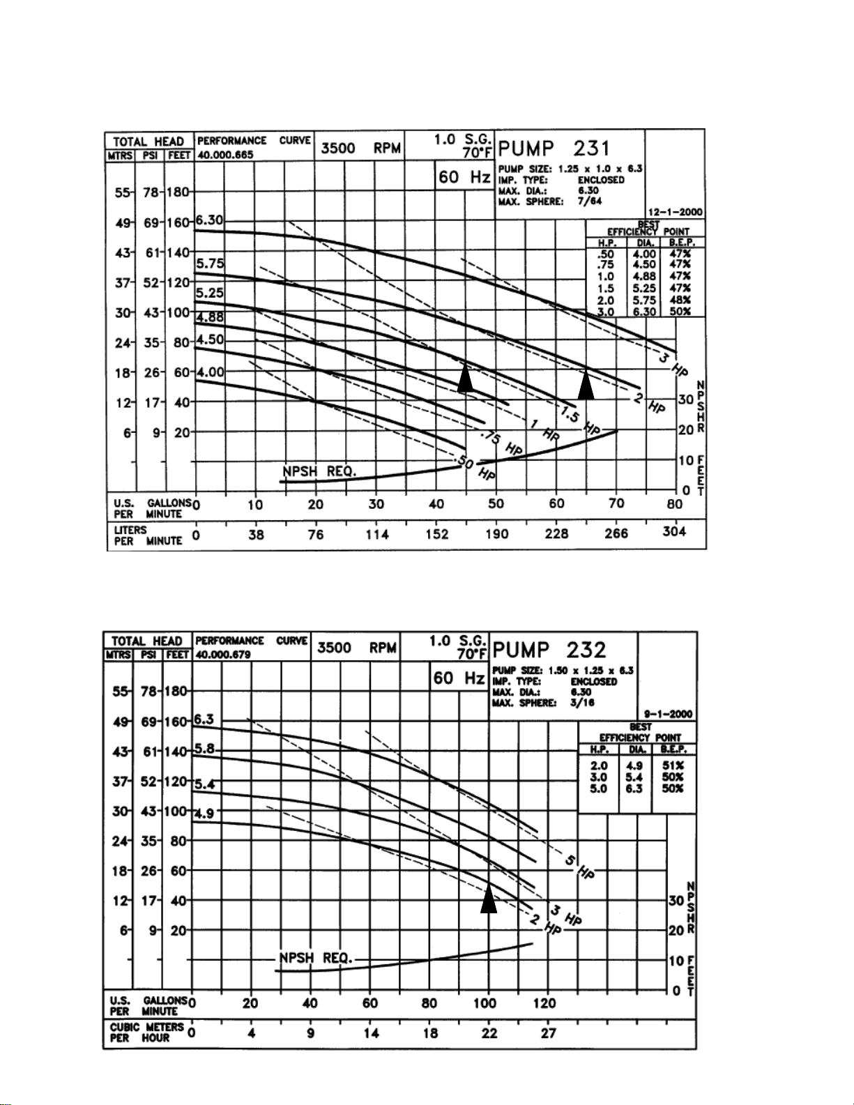
FTS-20-045
Flow Rate: 45 gpm
Horsepower: 1.0 HP
Impeller: ∅4.88"
FTS-24-065
Flow Rate: 65 gpm
Horsepower: 2.0 HP
Impeller: ∅5.75"
FTS-30-100
Flow Rate: 100 gpm
Horsepower: 2.0 HP
Impeller: ∅4.9"
T
A
A
A
A
A
L
L
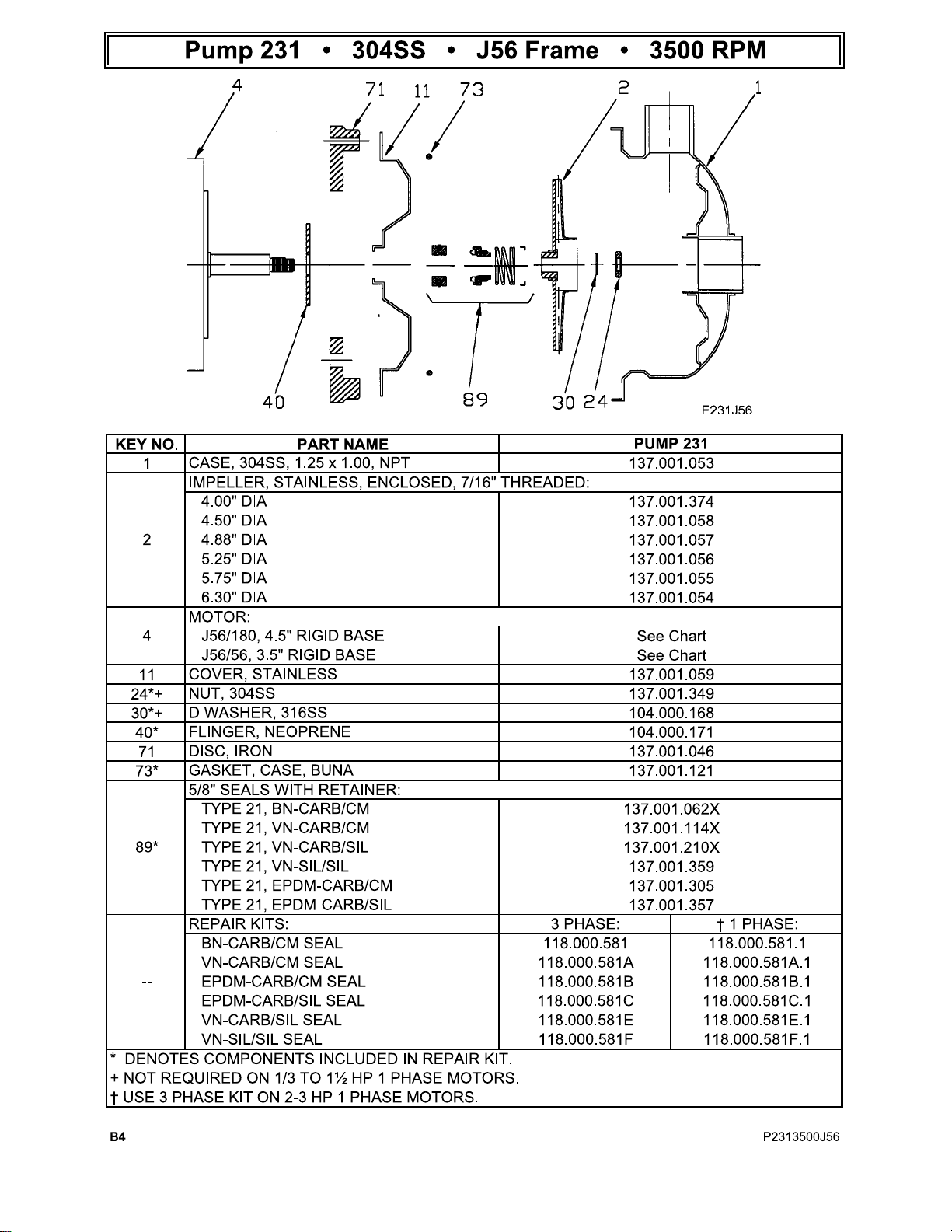
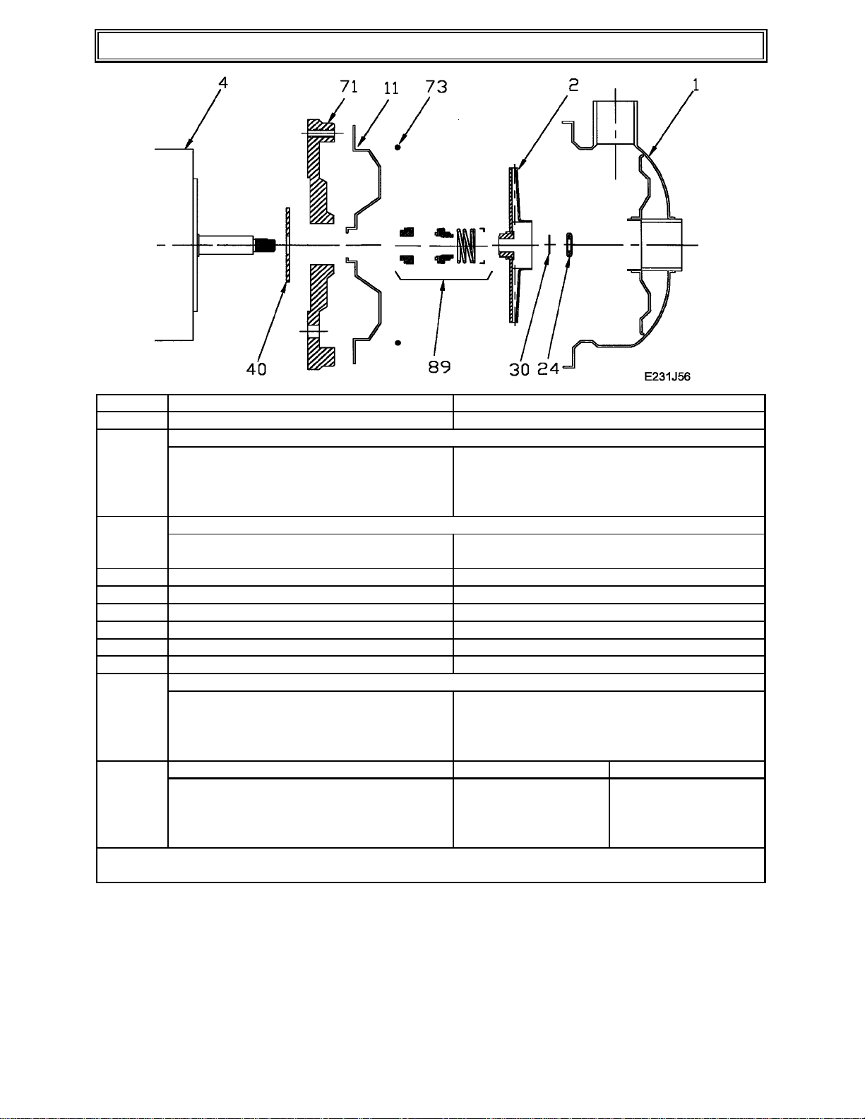
Pump 232 • 304SS • J56 Frame • 3500 RPM
KEY NO. PART NAME
CASE, 304SS, 1.5 x 1.25, NP
1
IMPELLER, STAINLESS, ENCLOSED, 7/16" THREADED:
4.90" DI
2
5.40" DI
5.80" DI
6.30" DI
MOTOR:
4
J56/180, 4.5" RIGID BASE
J56/56, 3.5" RIGID BASE
11
24*
30*
40*
71
73*
89*
--
* DENOTES COMPONENTS INCLUDED IN REPAIR KIT.
† USE 3 PHASE KIT ON 2-3 HP 1 PHASE MOTORS.
COVER, STAINLESS
NUT, 304SS
D WASHER, 316SS
FLINGER, NEOPRENE
DISC, IRON
GASKET, CASE, BUN
5/8" SEALS WITH RETAINER:
TYPE 21, BN-CARB/SIL
TYPE 21, VN-CARB/SIL
TYPE 21, VN-S IL/SIL
TYPE 21, EPDM-CARB/SI
REPAIR KITS: 3 PHASE: † 1 PHASE:
BN-CARB/SIL SEAL 118.000.581 118.000.581.1
VN-CARB/SIL SEAL 118.000.581E 118.000.581E.1
VN-SIL/SIL SEAL 118.000.581F 118.000.581F.1
EPDM-CARB/SIL SEA
PUMP 232
137.001.314
137.001.318
137.001.317
137.001.316
137.001.315
See Chart
See Chart
137.001.059
137.001.349
104.000.168
104.000.171
137.001.046
137.001.121
137.002.401
137.002.390
137.002.406
137.002.258
118.000.581C 118.000.581C.1
D10 P2323500J56

SCOT
MOTORPUMP™
J56 & JM FRAME
STRAIGHT CENTRIFUGAL
304 STAINLESS STEEL PUMP NO. 230, 231, 232, 236
INSTALLATION OPERATION MAINTENANCE
INCLUDES MECHAN ICAL SEAL REPLACEMENT
Check pump for shortage and damage immediately upon
arrival. Note damage or shortage on freight bill (bill of
lading); immediately file claim with carrier.
EXTERIOR — Pay particular attention to conduit box,
external hardware and accessories. Touch up abrasions
or scratches with approved paint.
INTERNAL — If extensive or serious external damage
is noted, if impeller is damaged (look in ports), or if shaft
binds or sticks, disassemble as required to permit
internal inspection.
HANDLING
Handle with care. Dropping or jarring can seriously damage motor bearings or break pump parts. Lift with device
having capacity for pump weight, and use lifting hooks or
eye bolts (if provided) or rig double sling around motor
frame and pump casing. Do not use sling through pump
motor adapter nor around suction and discharge flanges.
INSTALLATION
Location — Pum p location should provide the following:
1. Install as close to suction supply as possible.
2. Shortest and most direct suction pipe practical.
Suction lift must not exceed limit for pump. NPSH
available must equal or exceed pump requirement.
3. Suction port below pumping level to provide priming.
4. Room for inspection and maintenance.
5. Correct power supply to motor; all wiring should
meet National Electrical and Local Codes and
Regulations.
6. If outdoors, protection from the elements, freezing
and water damage due to flooding.
Piping — Suction and discharge gauges are useful to
check pump operation and are excellent trouble indicators. Install gauges in the lines if pump ports do not have
gauge taps. Observe these precautions when installing
piping:
1. Support close to, but independently of pump.
2. Use the next larger pump size for suction and discharge.
3. Keep as straight as possible. Avoid bends and fittings.
4. Remove burrs, sharp edges, ream pipe cuts, and
make joints air-tight.
5. Don’t spring pipe to make connections. Strain must
not be transmitted to pump.
6. Allow for pipe expansion with hot fluids; expansion
joints are not recommended.
Suction — Size and install suct ion piping to keep pres-
sure loss at minimum and to provide correct NPSH by
observing the following:
1. The suction pipe should be equal in size or preferabl y
one size larger than the suction connection of the
pump. If pipe is larger than the pump suction, an
eccentric pipe reducer should be used at the pump.
2. Pipe should slope upward to pump, even for horizon-
tal run.
3. Use 45-degree or long-sweep 90-degree elbows.
4. A valve in the suction is necessary only on positive
suction head installation and must not be used to
throttle the pump. The suction valve should be
installed for maintenance purposes only.
Discharge — Pumps per mit discha rge port locat ion a t
two positions, 30 degrees apart. Change by removing
cover bolts, rotate casing, and replace bolts. Do not slice
O-ring. Scot does not recommend bottom vertical, 3:00
or 9:00 discharge positions due to erratic pump performance. Ensure there is adequate clearance with selected
position between wall or tank, motor conduit box, and
grease fittings. Casing may extend beyond base or feet.
1 Short discharge lines may be the same size as the
discharge port. Long runs require a pipe larger than
the discharge port.
2. Long horizontal runs require a grade as even as pos-
sible. Avoid high spots and loops. Trapped air will
throttle flow and may result in erratic pumping.
3. Install check and gate valves in discharge line; check
valve (if used) between pump and gate valve.
• Cedarburg, WI 53012 • P.O. Box 28 6 • 262-377-700 0 • FAX 262-377-7330
Replaces Jan 2005
SCOT DIVISION OF ARDOX CORP. — HOME OFFICE
NOVEMBER 2009
61.000.281
OPERATION
Pre-Start — Before initial start of the pump, check as
follows:
1. The rotation must be checked upon installation.
Close, then break the contacts quickly and observe
the rotation of the exposed portion of the rotating
part s. Rotatio n must ag ree with the rotati on arrow on
the motor. For all pumps, the standard rotation is
counterclockwise when viewed from the suction
end. Motor wiring is easily changed in the field.
Observe the wiring diagram on the inside of the terminal box cover, or on the motor nameplate.
2. Check voltage, phase and frequency of line circuit
with motor nameplate.
3. Check suction and discharge piping and pressure
gauges for proper operation.
4. Assure that pump is full of liquid (primed).
Priming — If pump is inst alled with a positive head on
the suction, prime by opening suction valve and allowing
liquid to enter the casing, at the same time venting all air
out of the top of the casing.
If pump is installed with a suction lift, priming must be
done by other methods, such as foot valves, ejectors, or
by manually filling casing and suction line.
CAUTION - DO NOT RUN PUMP DRY. Serious damage
may result if started dry.
Temperature — Total temperature, not the r ise, is the
measure of safe operation for a motor. If temperature by
thermometer exceeds limits for insulation class, investigate and change operating conditions.
Labeled Motors — It is imperative for repair of a
motor with Underwriters’ Laboratories label that original
clearances be held; that all plugs, screws, other hardware be fastened securely, and that parts replacements
be exact duplicates or approved equals. Violation of any
of the above invalidates Underwriters’ label.
Lubrication — Pumps should require no mainte-
nance, other than the motor bearings, according to the
following instructions:
DOUBLE SHIELDED. When double shielded prelubricated bearings are furnished, no lubrication is required for
the life of the bearings. Inspect bearings periodically to
determine the condition of the grease and replace the
bearings if necessary.
SINGLE SHIELDED W/GREASE FITTING PROVISIONS.
When single shield bearings are furnished, periodic
inspection, cleaning and relubrication is required. See
motor manufacturer’s specific instructions for
lubrication.
Starting — Proceed as follows to start pump:
1. Close drain valves and valve in discharge line.
2. Open fully all valves in the suction line.
3. Prime the pump. If pump does not prime properly, or
loses prime during start-up, shut down and correct
condition before repeating procedure.
4. For pumps moving high temperature liquids, open
warm-up valve to circulate liquid for preheating.
Close valve after pump has warmed up.
5. Start the motor (pump).
6. When pump is operating at full speed, open discharge valve slowly.
Running — Periodically inspect pump while running,
but especially after first start and following repair.
1. Check pump and piping for leaks. Repair immediately.
2. Re cord pressu re g auge readin gs for future reference.
3. Record voltage, amperage per phase, and kW (if an
indicat ing wa t tme t er is a va il a ble ).
4. Adjust pump output capacity with discharge valve.
DO NOT throttle suction line.
Freezing Protection — Protect pumps shut down
during freezing conditions by one of the following methods:
1. Drain pump; remove all liquid from the casing.
2. Keep fluid moving in pump and insulate or heat the
pump to prevent freezing. If heated, do not let temperature go above 100 to 150 degrees F.
3. Fill pump completely with antifreeze solution.
MAINTENANCE
Cleaning — Remove oil , dust, dirt, water, chemicals
from exterior or motor and pump. Keep motor air inlet
and outlet open. Blow out interior of open motors with
clean compressed air at low pressure. Regularly drain
moisture from TEFC motors.
MECHANICAL S EAL REPLACEMENT
J56 FRAME MOTOR, PUMP NO. 230, 2 31, 2 32
A.) Disassembly:
1. Turn off power.
2. Close suction and discharge valves.
3. Drain pump.
4. Remove bolts holding base to foundation
5. Remove pipe connections from suction and discharge.
6. Remove pump from system.
7. Remove case.
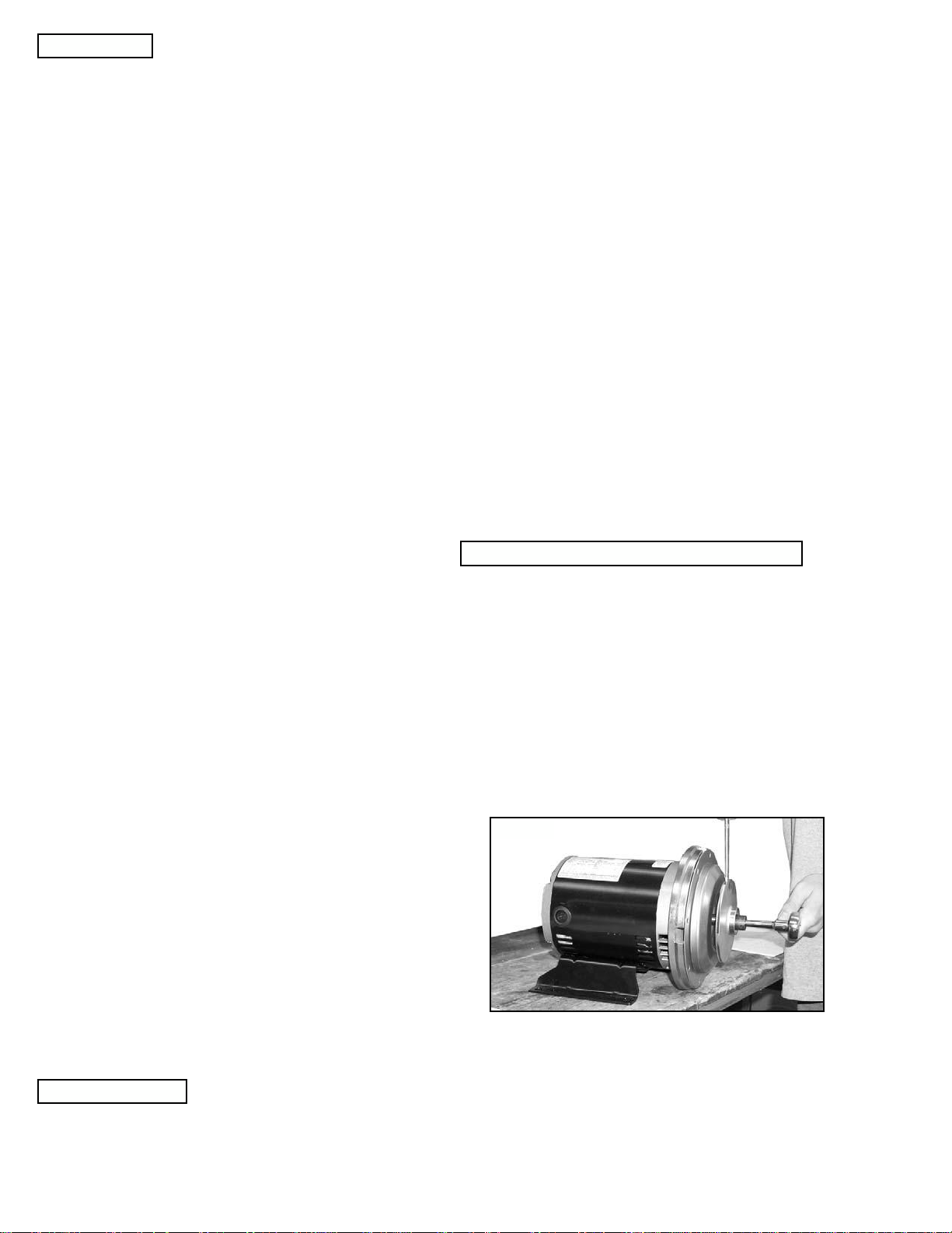
8. Insert a screwdriver in one of the impeller waterway passages and back off the im peller nut as
shown in Figure 1.
Figure 1
9. Remove motor shaft end cap. Insert a screwdriver in slot of motor shaft. While holding shaft
against rotation, unscrew impeller from shaft by
turning counterclockwise when facing impeller
(Figure 2).
10. Pry off rotating member of mechanical seal from
motor shaft by using (2) screwdrivers. Be careful not to damage the pump cover. See Figure 3.
 Loading...