

Page 1
COMPANY
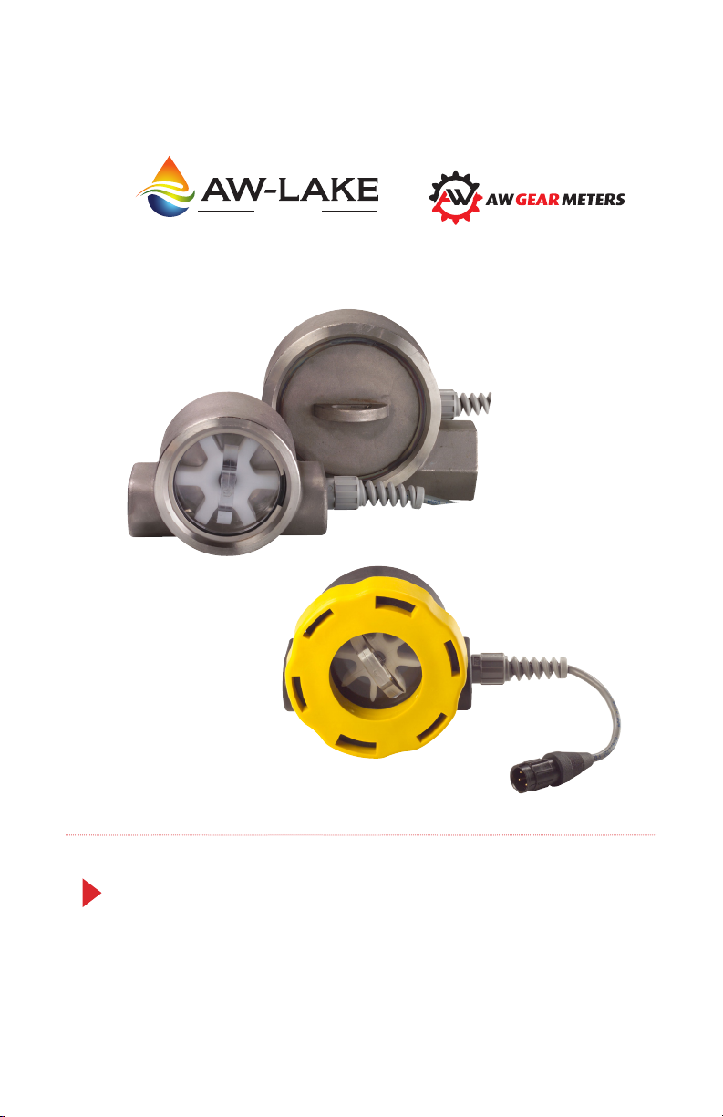
Paddle Wheel Turbine Flow Meters
Installation, Operating &
Maintenance Manual
Page 2
Mechanical Specications
Flow Meter with Polypropylene Body (ES version)
Maximum Operating Pressure:
150 PSIG
Maximum Operating Temperature:
20-150°F
Flow Measuring Range:
0.5-15 GPM (2-60 LPM)
Turn Down Ratio:
10:1
Wetted Components
Component Materials
Casing Glass-Filled Polypropylene
Cover Clear Polycarbonate
Seal Buna-N (Other options available)
Turbine Acetal Copolymer
Bearing PEEK (Polyetheretherketone)
Shaft Stainless Steel
Non-Wetted Components
Component Materials
Encapsulant Epoxy
Strain Relief Nylon
Lock Ring Glass-Filled Polypropylene
Wire Insulation High-Temperature PVC
2
Page 3
Flow Meter with Stainless Steel Body
Maximum Operating Pressure:
With Clear Cover:
to 200 PSIG (14 bar)
With Optional Stainless Steel Cover:
to 500 PSIG (34 bar)
Fluid Temperature Range:
20-225°F (-7° to 107°)
Flow Measuring Range:
1/2” porting: 0.5–15 GPM (2–60 LPM)
3/4” – 1” porting: 1.5–50 GPM (60–200 LPM)
Turn Down Ratio:
10:1
Wetted Components
Component Materials
Casing Stainless Steel 316
Cover Stainless Steel 316 (oponal clear polycarbonate)
Seal Buna-N® (other opons available)
Turbine Acetal Copolymer
Bearing PEEK (Polyetheretherketone)
Sha 316 Stainless Steel
Non-Wetted Components
Component Materials
Encapsulant Epoxy
Strain Relief Nylon
Lock Ring Stainless Steel
Wire Insulaon High-Temperature PVC
Note: Buna-N is a registered trademark of Chemische Werke Huls.
3
Page 4

Electronic Specifications
4-20 mA version
Power Requirements 12-35 VDC, loop powered
Load driving capacity Use the following equation to calculate
maximum load resistance: Max Loop Load (�)
= 50 (Power supply volts – 12).
Maximum Transmission Distance Limited only by wire resistance & supply
Response time 2 seconds to 90% (step change)
Resolution Innite
Over-current limit Self limiting at 35 mA
Other protection Reverse polarity
Power Requirements 12-35 VDC
Maximum Transmission Distance 200 feet recommended
Switch Contact Form C, 5A max 120 or 240 VAC
Hysteresis 5% of set point maximum
voltage
Relay Output
Set Point Repeatability 1% of full scale
0-5 VDC version
Power Requirements 12-35 VDC
Maximum Current 25 mA DC
Minimum Load resistance 1000 Ohms
Maximum Transmission Distance 200 feet recommended
Resolution Infinite
Response time < 5 seconds to 90% (step change)
4
Page 5
Pulse Output Version
E
F
D*
D
C
B
A
+
Power Requirements 12-24 VDC
Response Time <100 mS
Maximum Current 25 mA DC
Maximum Transmission Distance 200 feet recommended
Minimum Load Resistance 1000 Ohms
Protecon Short circuit & reverse polarity
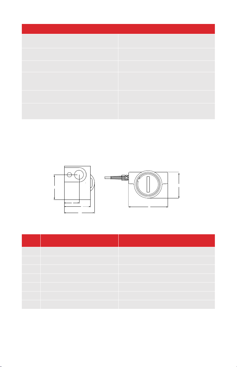
Mechanical Dimensions
DIM 1/2” NPTF 3/4” NPTF - 1” NPTF
A 1.94” (49mm) 3.06” (78mm)
B 1.13” (29mm) 1.33” (34mm)
C 2.00” (51mm) 2.46” (62mm)
D 2.45” (62mm) 2.78” (71mm)
D* 2.45” (62mm) 2.88” (73mm)
E 3.70” (94mm) 5.25” (133mm)
F 2.63” (67mm) 3.80” (97mm)
*Dimensions with clear polycarbonate cover installed.
5
Page 6

Introduction
This manual is a service guide produced by the manufacturer. The manual
provides specific procedures and/or illustrations for installation, inspection,
cleaning and filtration of all KW Series flow meters. When properly followed,
these procedures will keep your paddle wheel flow meter operating dependably
for many years.
It is important for operators and maintenance personnel to be safety conscience
when operating or repairing equipment. Developing a thorough knowledge of
the precautionary areas and following safe operating procedures, can prevent
equipment damage and/or personal injury.
Before making any repair, read all of the repair procedures to learn the
correct method and all precautions.
Description of Operation
The paddle wheel flow meters integrate rugged tangential turbine technology with
a precision electronic output signal hermetically encapsulated within the body
of the meter. The flow transmitter is ideal for measuring flow rates in cooling
circuits, HVAC systems and batching operations.
Additional features are:
• Simple in-the-field serviceability of its moving components.
• The integral 4-20mA circuit design eliminates the need for separate signal
conditioning modules.
• Units come factory calibrated to your system requirements.
• The low impedance 4-20mA circuit can transmit a “clean” signal over lowcost wire for several thousand feet without degradation.
• Accurately measures flow in both directions.
Installation - Mechanical
1. The KW flow meter has NPT (National Pipe Thread) plumbing connections.
Lake Monitors recommends that a paste type pipe sealant be used on these
threads. [Teflon tape sealant can be used as long as it is applied in such
a way that it will not enter the flow stream. Pieces of Teflon tape can wrap
around the turbine andimpede its rotation.]
6
Page 7
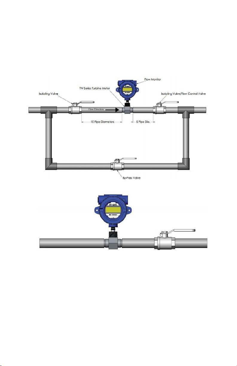
2. The recommended mounting orientation would be any plane that will place
the axis of the turbine horizontal with respect to the ground. The unit will
operate satisfactorily with its axis at angles other than horizontal, but side
loading of the bearing surfaces will lead to premature wear of the rotating
parts.
3. For optimum flow meter performance a minimum length of upstream and
downstream piping is required. It is recommended that a minimum length
equal to 10 pipe diameters of straight pipe be installed directly on the
upstream side of the flow meter and 5 pipe diameters on the downstream
side of the flow meter. This helps to eliminate turbulence in the fluid. Having
shorter pipe lengths, other system components and elbows to close to the
flow meter may adversely affect the accuracy and repeatability of the flow
meter. Piping should be the same size as the meter bore or port size. Do
not locate the flow meter or the connection cable close to electric motors,
transformers, sparking devices, high voltage lines or place connecting cable
in a conduit with wire supplying power for such devices. These devices can
7
Page 8

induce false signals in the flow meter coil or cable, causing the meter to
read inaccurately.
4. It is recommended that the meter be installed in such a position that the
round access cover can be removed for cleaning and turbine servicing. It
is also recommended that a union be placed near the sensor to allow easy
removal.
Installation - Electronic (4-20mA Only)
The KW circuit is a two-wire loop-powered design that transmits a 4-20mA
signal that is proportional to flow rate. The noise-immune current transmission
from the sensor can be routed with low cost two conductor twisted-pair cable.
The circuit operates on 12-35 Vdc and requires a source capable of supplying at
least 24mA of current. The circuit has built in polarity protection and over-current
limiting to protect both the transmitter and what the transmitter is connected to.
1. Connect the red wire (pin 1 for units with the electronic disconnect option)
from the transmitter sensor to the positive 12-35 Vdc power supply output.
2. Connect the black wire (pin 2 for units with the electronic disconnect option)
from the transmitter to the positive side of the loop load (resistor, chart
recorder, data acquisition board, meter, etc.). This connection may be
labeled “4-20mA Input” or “4-20mA (+)” on some devices.
3. If applicable, connect the negative side of the loop load to negative side of
the power supply.
4. Apply power to the system.
5. If everything is operating correctly, the green LED on the meter will illuminate
and 4mA will be flowing in the loop. As the flow rate increases, the intensity
of the green LED will increase in proportion to the mA output signal for
trouble shooting purposes.
If the LED does not illuminate:
• Check wiring terminations for good connections
• Check wiring polarity
• Verify correct supply voltage
• Ensure that the load impedance is within allowable limits
• Apply the DC supply voltage directly across the sensor wires. If the LED
does illuminate, the load is either: too great of impedance or an open
circuit. If the LED does not illuminate, the sensor’s lead wires or circuit are
defective.
8
Page 9

Installation - Electronic (0-5Vdc Output Only)
1. Connect the red wire (pin 1 for units with the electronic disconnect option)
from the sensor to the positive terminal of the 12-35 VDC power supply.
2. Connect the black wire from the transmitter (pin 2 for units with the electronic
disconnect option) to the negative terminal of the 12-35 VDC power supply.
3. Connect the green wire from the transmitter (pin 3 for units with electronic
disconnect) to the (+) 0-5 Vdc input of the data acquisition device. This
connection may be labeled “Voltage Input” or “Analog Input” on some
devices.
4. If applicable, connect the negative side of the power supply to the negative
side of the pulse input.
5. Apply power to the system.
6. If everything is operating correctly, the green LED will illuminate brightly and
the data acquisition device should show an increase in flow rate as fluid
starts flowing through the sensor.
If data acquisition device does not show an increase in flow rate:
• Check wiring terminations for good connections
• Verify that the LED is illuminated
• Verify that the DC supply voltage is between 12 and 35 Vdc
•
Installation – Electronic (Pulse Output Only)
The KW pulse output circuit is a three-wire DC-powered design that transmits a
frequency proportional to flow rate. The circuit operates on 5- 24 Vdc and will
consume a maximum of 25 mA from the power supply.
1. Connect the red wire (pin 1 for units with the electronic disconnect option)
from the sensor to the positive terminal of the 5-24VDC power supply.
2. Connect the black wire from the transmitter (pin 2 for units with the electronic
disconnect option) to the negative terminal of the 5-24 Vdc power supply.
3. Connect the green wire from the transmitter (pin 3 for units with electronic
disconnect) to the (+) pulse input of the data acquisition device. This
connection may be labeled “Pulse In” or “DC Input” on some devices.
4. If applicable, connect the negative side of the power supply to the negative
side of the pulse input.
5. Apply power to the system.
6. If everything is operating correctly, the data acquisition device should begin
“counting” pulses when fluid starts flowing through the sensor.
9
Page 10

If the data acquisition device is not “counting”:
• Check wiring terminations for good connections
• Verify correct supply voltage and current
7. The installation should be complete. The relationship between the frequency
output and flow rate is shown in the graphs above.
Installation – Electronic (Relay Output Only)
1. Connect the red wire from the sensor to the positive terminal of the 12-35
Vdc power supply.
2. Connect the black wire from the transmitter to the negative terminal of the
12-35 Vdc power supply.
3. (Versions with stainless steel sensor body only) Be sure to properly ground
the KW sensor housing by connecting a ground wire to the sensor body.
This step may be unnecessary if the piping system that the flow sensor is
plumbed into is already connected to Earth ground.
4. Wire the appropriate relay contacts to the load that is to be switched per
Table 1 below.
5. If the unit is operating correctly, the green power indication LED and the red
relay status LED should illuminate after the DC supply voltage is turned on.
As fluid flow is increased above the factory-adjusted set point, the red relay
status LED should turn off.
If the LEDs do not illuminate when power is applied:
• Check wiring terminations for good connections
• Verify that the DC supply voltage is between 12 and 35 Vdc
Table 1: Wiring Connections
Wire Color Connection
Red +12-35 Vdc
Black DC Ground
Green Relay Common
White Relay Normally Closed Contact
Brown Relay Normally Open Contact
Note: Relay condion shown is with power on & ow rate above setpoint.
10
Page 11
Set Point Adjustment (Relay Output Only)
1. Adjust the flow rate through the line in which the KW meter is installed to the
rate that corresponds to the desired relay trip point.
2. If the red LED on the back side of the sensor is not illuminated, use a small
flat bladed screwdriver to slowly turn the adjustment screw on the set point
potentiometer counter-clockwise until the red LED illuminates.
3. If the red LED is already illuminated, turn the adjustment screw on the
potentiometer clockwise until red LED turns off. Next, slowly rotate the
adjustment screw counter-clockwise until the red LED illuminates.
4. Once the set point has been adjusted, the relay will operate as shown in the
Truth Table illustrated in Table 2 below.
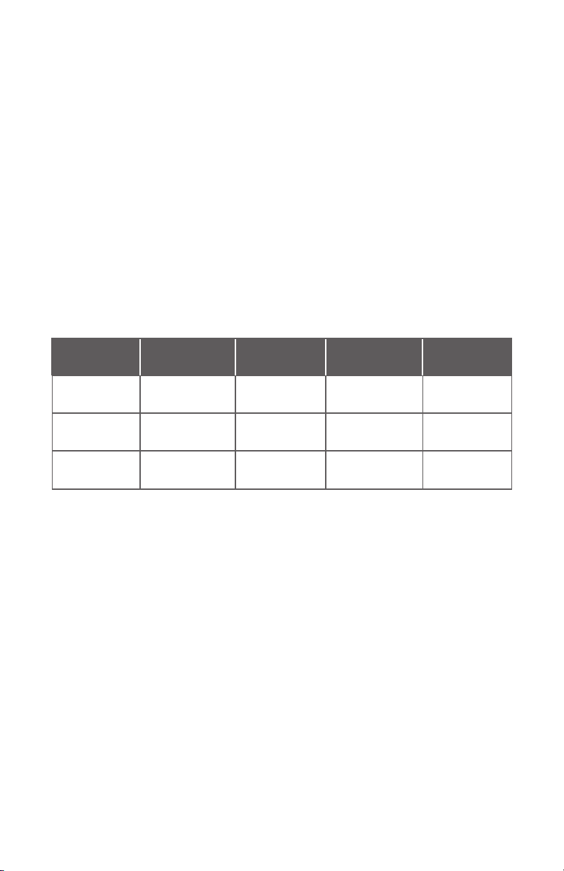
Table 2: Truth Table - Relay Operation
Condition Relay NC
Contact
Flow rate <
set point
Flow rate >
set point
Loss of power
to sensor
Open Closed Illuminated Illuminated
Closed Open Not Illuminated Illuminated
Open Closed Not Illuminated Not Illuminated
Relay NO
Contact
Red LED Green LED
Service and Maintenance
The sensor is designed to provide years of low maintenance service in industrial
environments. As with all mechanical rotating devices, the bearing surfaces will
wear with use. The life of the parts will depend on factors such as cleanliness of
the fluid, media, mounting orientation, temperature, fluid velocity and frequency
of operation. The KW meter was designed with simple field-replacement of the
rotating parts in mind. To inspect or replace the rotating components:
1. Relieve pressure in the piping system.
2. Remove the retainer ring that secures the turbine access cover.
3. Remove the access cover with pliers, taking care not to damage the o-ring
seal.
4. Pull out the turbine assembly and the shaft.
5. Inspect the shaft for things that may have wrapped around it.
6. Inspect the turbine bearing surface for wear and elongation. Replace as
11
Page 12

necessary.
7. Clean any rust off of the magnets that may have accumulated.
8. Reassemble the unit by placing the turbine into the body cavity with the
two magnet pockets facing inward. Place the shaft into the turbine hole and
guide it into the retaining hole in the body cavity. Lubricate the o-ring seal
with some glycerin or other lubricant and press it into the pocket of the body.
Replace the retaining ring securely before applying pressure to the system.
Circuit recalibration (4-20mA version):
1. Place a milliamp meter into the current loop.
2. Turn off the flow going though the meter. Adjust the OFFSET control for a
reading of 4mA on the milliamp meter.
3. Adjust the flow rate though the meter to full flow rate. Adjust the SPAN
control for a reading of 20mA on the milliamp meter. The two controls are
not interactive, so further adjustment should not be necessary.
Circuit recalibration (0-5Vdc version):
1. Place a voltmeter across the black & green wires of the sensor pigtail.
2. Turn off the flow going though the sensor. Verify a reading of less than 50
mVdc on the voltmeter.
3. Adjust the flow rate though the meter to full-scale flow rate. Adjust the SPAN
control for a reading of 5 Vdc on the voltmeter.
12
Page 13

COMPANY
262.884.9800 | www.aw-lake.com
8809 Industrial Drive, Franksville, WI 53126
13
 Loading...