

Page 1
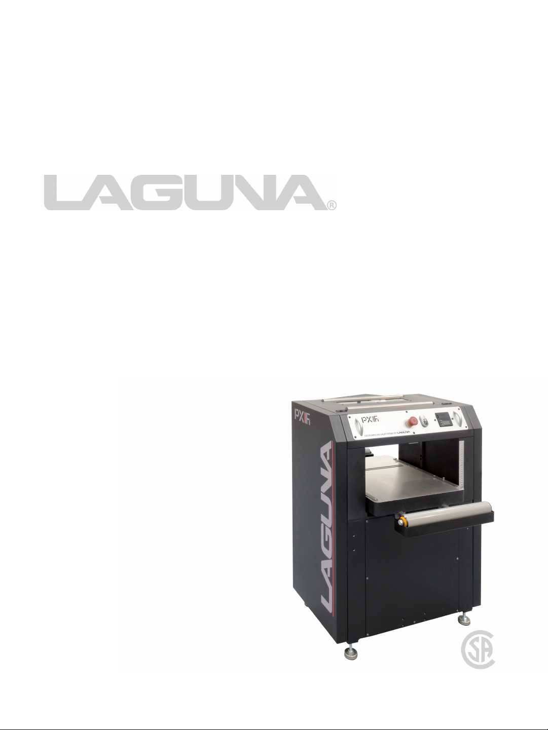
PXl16 Sheartec:II Planer
Owner's Manual
MPLANPX16-0130
3/10/2021
Page 2
For immediate service on any Laguna Tools products:
+1 (949) 474-1200
Laguna Tools, Inc. LAGUNA® and the LAGUNA Logo® are the registered trademarks of
Laguna Tools, Inc. All rights reserved. 04/01/2019
LAGUNA AMERICAN HEADQUARTERS
Texas: 744 Refuge Way Suite 200, Grand Prairie, Texas 75050, U.S.A. Phone:
+1-800-332-4094
Huntington Beach: 7291 Heil Ave Huntington Beach, CA 92647, U.S.A. Phone:
+1-949-474-1200
South Carolina: 825 Bistline Dr. Ste 101, West Columbia, SC 29172, U.S.A. Phone:
+1-800-234-1976
Minnesota: 5250 West 74th St, Edina, MN 55439, U.S.A Phone: +1-949-474-1200
lagunatools.com
supermaxtools.com
lagunacleanair.com
lagunalathe.com
LAGUNA EUROPE
Walker Rd, Bardon Hill, Coalville LE67 1TU, United Kingdom. Phone: +44-1530-516921
lagunatools.uk
DAKE CORPORATION
724 Robbins Road, Grand Haven, MI 49417, United States +1-800-937-3253
dakecorp.com
www.lagunatools.com
Page 3
CONTENTS
PXl16 Sheartec:II Planer
Safety ........................................................... 4
Electrical Safety ............................................. 9
Specifications ............................................... 13
Machine Overview ......................................... 14
Setup .......................................................... 16
Placement & Unboxing ............................ 16
Inventory List .......................................... 18
Assembling ............................................ 19
Operation ..................................................... 25
Maintenance ................................................ 26
Lubrication ................................................... 34
Troubleshooting ............................................ 35
Wiring .......................................................... 36
Replacement Parts Diagram .......................... 37
Replacement Parts Table ............................... 40
Warranty ...................................................... 46
Page 4
4 PXl16 Sheartec:II Planer \ Safety
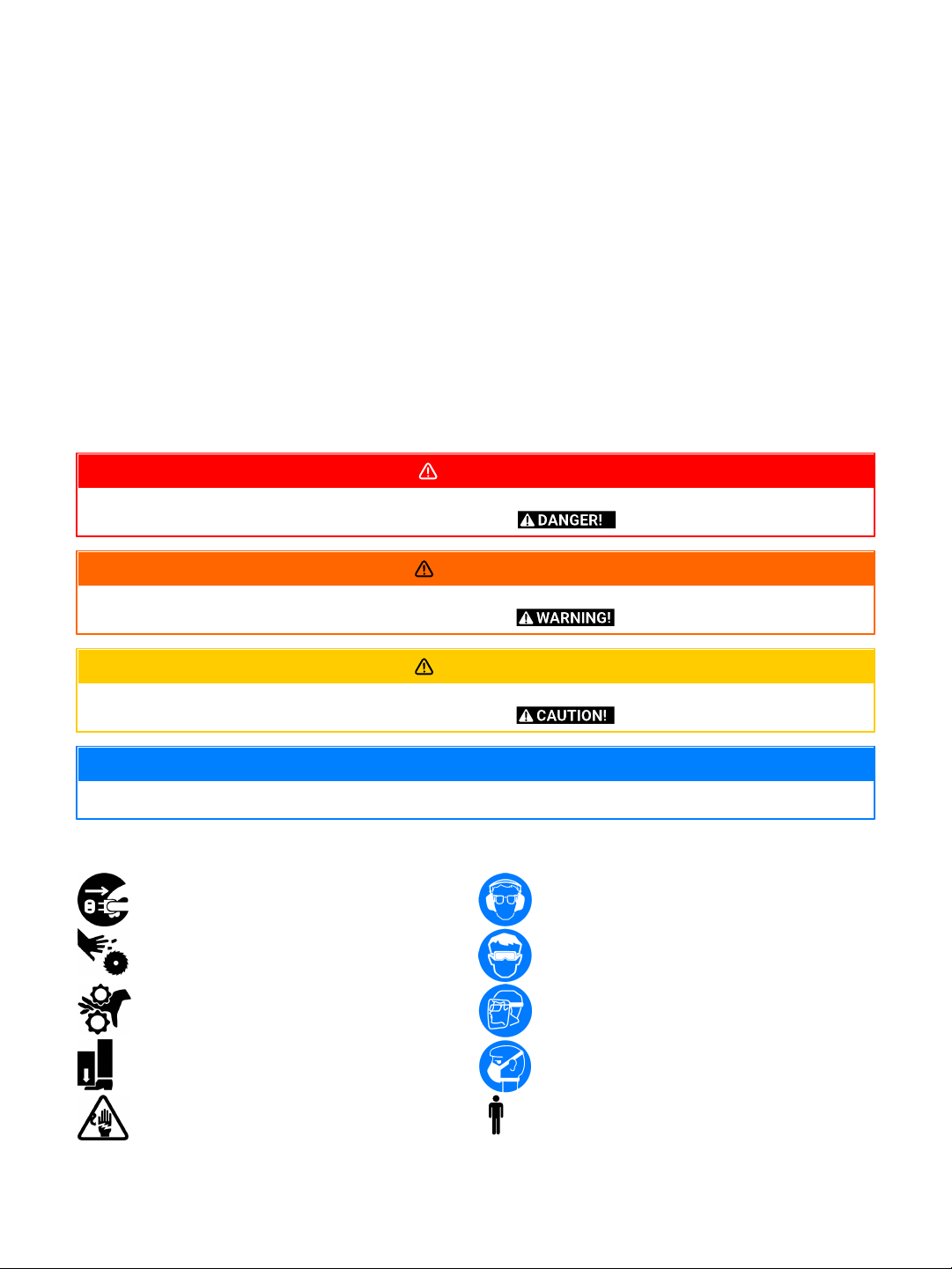
A POTENTIALLY HAZARDOUS SITUATION WHICH, IF NOT AVOIDED, COULD RESULT IN DEATH OR SERIOUS INJURY.
SOMETIMES DISPLAYED AS
A POTENTIALLY HAZARDOUS SITUATION WHICH, IF NOT AVOIDED, COULD RESULT IN DEATH OR SERIOUS INJURY.
SOMETIMES DISPLAYED AS
A POTENTIALLY HAZARDOUS SITUATION WHICH, IF NOT AVOIDED, MAY RESULT IN MINOR OR MODERATE INJURY.
SOMETIMES DISPLAYED AS
NOTICE!
A HELPFUL TIP FROM OUR TECHNICAL STAFF. SOMETIMES DISPLAYED AS NOTICE!
Disconnect from power before proceeding.
Wear ear protection.
Be aware of possible laceration danger.
Wear Eye Protection.
Be aware of possible crushing danger.
Wear a full face shield.
Be aware of possible crushing danger.
Wear lung protection.
Electrical Hazard.
Requires X People
Safety
Read and understand all warnings and operation instructions before using any tool or equipment. Always
follow basic safety precautions to reduce the risk of personal injury. Improper operation, maintenance or
modification of tools or equipment could result in serious injury and property damage. There are certain
applications for which tools and equipment are designed. This product should NOT be modified and/or used
for any application other than for which it was designed.
It is important for you to read and understand this manual. The information it contains relates to protecting
your safety and preventing problems.
Safety Call-outs
DANGER!
WARNING
Safety Symbols
CAUTION!
..X
Page 5
PROP 65 WARNING
SOME DUST CREATED BY POWER SANDING, SAWING, GRINDING, DRILLING, AND OTHER CONSTRUCTION ACTIVITIES
CONTAINS CHEMICALS KNOWN TO THE STATE OF CALIFORNIA TO CAUSE CANCER, BIRTH DEFECTS OR OTHER
REPRODUCTIVE HARM. SOME EXAMPLES OF THESE CHEMICALS ARE:
·
LEAD FROM LEAD-BASED PAINTS.
·
CRYSTALLINE SILICA FROM BRICKS, CEMENT AND OTHER MASONRY PRODUCTS.
·
ARSENIC AND CHROMIUM FROM CHEMICALLY-TREATED LUMBER.
YOUR RISK FROM THESE EXPOSURES VARIES, DEPENDING ON HOW OFTEN YOU DO THIS TYPE OF WORK. TO REDUCE
YOUR EXPOSURE TO THESE CHEMICALS: WORK IN A WELL VENTILATED AREA, AND WORK WITH APPROVED SAFETY
EQUIP-MENT, SUCH AS THOSE DUST MASKS THAT ARE SPECIALLY DESIGNED TO FILTER OUT MICROSCOPIC
PARTICLES.
·
THIS MACHINE WAS DESIGNED FOR CERTAIN APPLICATIONS ONLY. WE STRONGLY RECOMMEND THAT THIS
MACHINE NOT BE MODIFIED AND/OR USED FOR ANY APPLICATION OTHER THAN THAT FOR WHICH IT WAS
DESIGNED. IF YOU HAVE ANY QUESTIONS RELATIVE TO A PARTICULAR APPLICATION, DO NOT USE THE MACHINE
UNTIL YOU HAVE FIRST CONTACTED THE MANUFACTURER TO DETERMINE IF IT CAN OR SHOULD BE PERFORMED
ON THE PRODUCT.
·
IF YOU HAVE ANY QUESTIONS RELATIVE TO ITS APPLICATION DO NOT USE THE PRODUCT UNTIL YOU HAVE
CONTACTED THE MANUFACTURER AND WE HAVE ADVISED YOU.
Machine & Workshop Safety Instructions
Read and understand all warnings and operating instructions before using this equipment. Failure to follow all
instructions listed below, may result in electric shock, fire, and/or serious personal injury or property damage.
Machinery can be dangerous if safe and proper operating procedures are not followed. As with all machinery, there are
certain hazards involved with the operation of the product. Using the machine with respect and caution will considerably
lessen the possibility of personal injury. However, if normal safety precautions are overlooked or ignored, personal
injury to the operator may result. Safety equipment such as guards, push sticks, hold-downs, feather boards, goggles,
dust masks and hearing protection can reduce your potential for injury. But even the best guard won’t make up for poor
judgment, carelessness or inattention. Always use common sense and exercise caution in the workshop. If a procedure
feels dangerous, don’t try it. Figure out an alternative procedure that feels safer. REMEMBER: Your personal safety is
your responsibility.
OWNER’S MANUAL. Read and understand this owner’s manual BEFORE using machine.
TRAINED OPERATORS ONLY. Untrained operators have a higher risk of being hurt or killed. Only allow
trained/supervised people to use this machine. When machine is not being used, disconnect power, remove switch keys,
or lock-out machine to prevent unauthorized use—especially around children. Make your workshop kid proof!
DANGEROUS ENVIRONMENTS. Do not use machinery in areas that are wet, cluttered, or have poor lighting. Operating
machinery in these areas greatly increases the risk of accidents and injury.
MENTAL ALERTNESS REQUIRED. Full mental alertness is required for safe operation of machinery. Never operate
under the influence of drugs or alcohol, when tired, or when distracted.
ELECTRICAL EQUIPMENT INJURY RISKS. You can be shocked, burned, or killed by touching live electrical components
or improperly grounded machinery. To reduce this risk, only allow qualified service personnel to do electrical installation
or repair work, and always disconnect power before accessing or exposing electrical equipment.
DISCONNECT POWER FIRST. Always disconnect machine from power supply BEFORE making adjustments, changing
tooling, or servicing machine. This prevents an injury risk from unintended start-up or contact with live electrical
components.
EYE PROTECTION. Always wear ANSI-approved safety glasses or a face shield when operating or observing machinery to
reduce the risk of eye injury or blindness from flying particles. Everyday eyeglasses are NOT approved safety glasses.
APPLICATIONS WARNING
5PXl16 Sheartec:II Planer \ Safety
WARNING!
Page 6

6 PXl16 Sheartec:II Planer \ Safety
WEARING PROPER APPAREL. Do not wear clothing, apparel or jewelry that can become entangled in moving parts.
Always tie back or cover long hair. Wear non-slip footwear to reduce risk of slipping and losing control or accidentally
contacting cutting tool or moving parts.
HAZARDOUS DUST. Dust created by machinery operations may cause cancer, birth defects, or long-term respiratory
damage. Be aware of dust hazards associated with each workpiece material. Always wear a NIOSH-approved respirator
to reduce your risk.
HEARING PROTECTION. Always wear hearing protection when operating or observing loud machinery. Extended
exposure to this noise without hearing protection can cause permanent hearing loss.
REMOVE ADJUSTING TOOLS. Tools left on machinery can become dangerous projectiles upon startup. Never leave
chuck keys, wrenches, or any other tools on machine. Always verify removal before starting!
USE CORRECT TOOL FOR THE JOB. Only use this tool for its intended purpose—do not force it or an attachment to do a
job for which it was not designed. Never make unapproved modifications, modifying tool or using it differently than
intended may result in malfunction or mechanical failure that can lead to personal injury or death!
AWKWARD POSITIONS. Keep proper footing and balance at all times when operating machine. Do not overreach! Avoid
awkward hand positions that make workpiece control difficult or increase the risk of accidental injury.
CHILDREN & BYSTANDERS. Keep children and bystanders at a safe distance from the work area. Stop using machine if
they become a distraction.
GUARDS & COVERS. Guards and covers reduce accidental contact with moving parts or flying debris. Make sure they
are properly installed, undamaged, and working correctly BEFORE operating machine.
FORCING MACHINERY. Do not force machine. It will do the job safer and better at the rate for which it was designed.
NEVER STAND ON MACHINE. Serious injury may occur if machine is tipped or if the cutting tool is unintentionally
contacted.
STABLE MACHINE. Unexpected movement during operation greatly increases risk of injury or loss of control. Before
starting, verify machine is stable and mobile base (if used) is locked.
USE RECOMMENDED ACCESSORIES. Consult this owner’s manual or the manufacturer for recommended accessories.
Using improper accessories will increase the risk of serious injury.
UNATTENDED OPERATION. To reduce the risk of accidental injury, turn machine OFF and ensure all moving parts
completely stop before walking away. Never leave machine running while unattended.
MAINTAIN WITH CARE. Follow all maintenance instructions and lubrication schedules to keep machine in good working
condition. A machine that is improperly maintained could malfunction, leading to serious personal injury or death.
DAMAGED PARTS. DAMAGED PARTS. Regularly inspect machine for damaged, loose, or improperly adjusted parts—or
any condition that could affect safe operation.
MAINTAIN POWER CORDS. When disconnecting cord-connected machines from power, grab and pull the plug—NOT the
cord. Pulling the cord may damage the wires inside. Do not handle cord/plug with wet hands. Avoid cord damage by
keeping it away from heated surfaces, high traffic areas, harsh chemicals, and wet/damp locations.
Machine & Workshop Safety Instructions
Read and understand all warnings and operating instructions before using this equipment. Failure to follow all
instructions listed below, may result in electric shock, fire, and/or serious personal injury or property damage.
Machinery can be dangerous if safe and proper operating procedures are not followed. As with all machinery, there are
certain hazards involved with the operation of the product. Using the machine with respect and caution will considerably
lessen the possibility of personal injury. However, if normal safety precautions are overlooked or ignored, personal
injury to the operator may result. Safety equipment such as guards, push sticks, hold-downs, feather boards, goggles,
dust masks and hearing protection can reduce your potential for injury. But even the best guard won’t make up for poor
judgment, carelessness or inattention. Always use common sense and exercise caution in the workshop. If a procedure
feels dangerous, don’t try it. Figure out an alternative procedure that feels safer. REMEMBER: Your personal safety is
your responsibility.
OWNER’S MANUAL. Read and understand this owner’s manual BEFORE using machine.
WARNING!
Page 7

TRAINED OPERATORS ONLY. Untrained operators have a higher risk of being hurt or killed. Only allow
trained/supervised people to use this machine. When machine is not being used, disconnect power, remove switch keys,
or lock-out machine to prevent unauthorized use—especially around children. Make your workshop kid proof!
DANGEROUS ENVIRONMENTS. Do not use machinery in areas that are wet, cluttered, or have poor lighting. Operating
machinery in these areas greatly increases the risk of accidents and injury.
MENTAL ALERTNESS REQUIRED. Full mental alertness is required for safe operation of machinery. Never operate
under the influence of drugs or alcohol, when tired, or when distracted.
ELECTRICAL EQUIPMENT INJURY RISKS. You can be shocked, burned, or killed by touching live electrical components
or improperly grounded machinery. To reduce this risk, only allow qualified service personnel to do electrical installation
or repair work, and always disconnect power before accessing or exposing electrical equipment.
DISCONNECT POWER FIRST. Always disconnect machine from power supply BEFORE making adjustments, changing
tooling, or servicing machine. This prevents an injury risk from unintended start-up or contact with live electrical
components.
EYE PROTECTION. Always wear ANSI-approved safety glasses or a face shield when operating or observing machinery to
reduce the risk of eye injury or blindness from flying particles. Everyday eyeglasses are NOT approved safety glasses.
WEARING PROPER APPAREL. Do not wear clothing, apparel or jewelry that can become entangled in moving parts.
Always tie back or cover long hair. Wear non-slip footwear to reduce risk of slipping and losing control or accidentally
contacting cutting tool or moving parts.
HAZARDOUS DUST. Dust created by machinery operations may cause cancer, birth defects, or long-term respiratory
damage. Be aware of dust hazards associated with each workpiece material. Always wear a NIOSH-approved respirator
to reduce your risk.
HEARING PROTECTION. Always wear hearing protection when operating or observing loud machinery. Extended
exposure to this noise without hearing protection can cause permanent hearing loss.
REMOVE ADJUSTING TOOLS. Tools left on machinery can become dangerous projectiles upon startup. Never leave
chuck keys, wrenches, or any other tools on machine. Always verify removal before starting!
USE CORRECT TOOL FOR THE JOB. Only use this tool for its intended purpose—do not force it or an attachment to do a
job for which it was not designed. Never make unapproved modifications, modifying tool or using it differently than
intended may result in malfunction or mechanical failure that can lead to personal injury or death!
AWKWARD POSITIONS. Keep proper footing and balance at all times when operating machine. Do not overreach! Avoid
awkward hand positions that make workpiece control difficult or increase the risk of accidental injury.
CHILDREN & BYSTANDERS. Keep children and bystanders at a safe distance from the work area. Stop using machine if
they become a distraction.
GUARDS & COVERS. Guards and covers reduce accidental contact with moving parts or flying debris. Make sure they
are properly installed, undamaged, and working correctly BEFORE operating machine.
FORCING MACHINERY. Do not force machine. It will do the job safer and better at the rate for which it was designed.
NEVER STAND ON MACHINE. Serious injury may occur if machine is tipped or if the cutting tool is unintentionally
contacted.
STABLE MACHINE. Unexpected movement during operation greatly increases risk of injury or loss of control. Before
starting, verify machine is stable and mobile base (if used) is locked.
USE RECOMMENDED ACCESSORIES. Consult this owner’s manual or the manufacturer for recommended accessories.
Using improper accessories will increase the risk of serious injury.
UNATTENDED OPERATION. To reduce the risk of accidental injury, turn machine OFF and ensure all moving parts
completely stop before walking away. Never leave machine running while unattended.
MAINTAIN WITH CARE. Follow all maintenance instructions and lubrication schedules to keep machine in good working
condition. A machine that is improperly maintained could malfunction, leading to serious personal injury or death.
DAMAGED PARTS. DAMAGED PARTS. Regularly inspect machine for damaged, loose, or improperly adjusted parts—or
any condition that could affect safe operation.
MAINTAIN POWER CORDS. When disconnecting cord-connected machines from power, grab and pull the plug—NOT the
cord. Pulling the cord may damage the wires inside. Do not handle cord/plug with wet hands. Avoid cord damage by
keeping it away from heated surfaces, high traffic areas, harsh chemicals, and wet/damp locations.
Planer Specific Safety Instructions
WARNING!
7PXl16 Sheartec:II Planer \ Safety
Page 8

8 PXl16 Sheartec:II Planer \ Safety
LIKE ALL MACHINES, THERE IS DANGER ASSOCIATED WITH THE MACHINE. INJURY IS FREQUENTLY CAUSED BY LACK
OF KNOWLEDGE OR FAMILIARITY. USE THIS MACHINE WITH RESPECT. IF NORMAL SAFETY PRECAUTIONS ARE
OVERLOOKED OR IGNORED, SERIOUS PERSONAL INJURY MAY OCCUR.
1. KICKBACK
"KICKBACK" IS WHEN THE WORK PIECE IS THROWN OFF THE PLANER TABLE BY THE CUTTER HEAD. THE "KICKBACK
ZONE", IS THE PATH DIRECTLY BACK THROUGH THE IN FEED TABLE. NEVER STAND OR ALLOW OTHERS TO STAND IN
THIS AREA DURING OPERATION. IF KICK BACK OCCURS, SEVERE INJURY MAY RESULT.
2. CUTTER HEAD ALIGNMENT
TO REDUCE THE POSSIBILITY OF KICKBACK, KEEP THE TOP EDGE OF THE OUT FEED TABLE ALIGNED WITH THE
CUTTER HEAD INSERT AT TOP DEAD CENTER (TDC).
3. SUPPORTING THE WORK
ONLY MAKE CUTS IF THE WORK PIECE IS STABLE AND NEVER ATTEMPT TO CUT UNSTABLE PLANKS, OR INJURY MAY
OCCUR.
4. CUTTING DEPTH
NEVER EXCEED THE MAXIMUM CUTTING DEPTH AS STATED IN THE SPECIFICATION FOR YOUR MACHINE. IT IS FAR
BETTER TO TAKE SEVERAL SMALL CUTS RATHER THAN LARGE CUTS.
5. DIRECTION OF CUT
PLANING AGAINST THE GRAIN OR PLANING END GRAIN IS DANGEROUS AND COULD PRODUCE CHATTER OR
EXCESSIVE CHIP OUT. ALWAYS PLANE WITH THE GRAIN.
6. GUARDS
GUARDS ARE DESIGNED TO REDUCE THE RISK OF INJURY. ALWAYS USE THE GUARDS. IF IT IS IMPERATIVE TO USE
THE MACHINE WITHOUT THE GUARDS, [RABBETING] ALWAYS REPLACE THE GUARDS.
7. CUTTING DIRECTION
ONLY CUT FROM THE IN FEED TABLE TO THE OUT FEED TABLE, AND ALWAYS COMPLETE THE CUT. DO NOT STOP THE
WOOD PROGRESS UNTIL THE JOB HAS CLEARED THE CUTTER HEAD COMPLETELY. ONLY CUT WITH THE GRAIN OR AT
A SLIGHT ANGLE TO THE GRAIN.
8. STOCK
YOUR SAFETY WILL BE GREATLY ENHANCED IF YOU ONLY USE GOOD LUMBER. ONLY WORK WITH LUMBER AFTER YOU
HAVE INSPECTED IT COMPLETELY. STAPLES, NAILS LOOSE KNOTS AND ANY OTHER METAL IN THE PLANK WILL
DAMAGE YOUR CUTTER HEAD AND COULD CAUSE INJURY AND OR FIRE. IF YOU HAVE ANY QUESTION ABOUT A PIECE
OF LUMBER, DO NOT USE IT.
Refer to them often and use them to instruct others.
SAVE THESE INSTRUCTIONS.
Page 9
Electrical Safety
·
RUNNING ON A DIFFERENT VOLTAGE THAN STATED BELOW WILL DAMAGE THE MACHINE. NEVER RUN THE
MACHINE IN WET OR DAMP CONDITIONS.
·
ELECTROCUTION, FIRE, SHOCK, OR EQUIPMENT DAMAGE MAY OCCUR IF MACHINE IS NOT PROPERLY GROUNDED
AND CONNECTED TO POWER SUPPLY.
MPLANPX16-0130
VOLTAGE
220V
PHASE
1 Phase
HERTZ
60Hz
FULL LOAD AMPERAGE
23 AMPS
PLUG/RECEPTACLE
Not Included
WIRING (Gauge)
See Jacket Printing
CIRCUIT BREAKER
30 Amp Minimum
WARNING!
Power Supply
A separate electrical circuit should be used for each machine. This circuit should not be less than the wiring
listed below and should be protected with an appropriate circuit breaker based on the total running and
start-up amperage's (listed below). If an extension cord is used, use only 3-wire extension cords which
have 3-prong grounding type plugs and matching receptacle which will accept the machine’s plug.
9PXl16 Sheartec:II Planer \ Electrical Safety
Below are RECOMMENDATIONS to be used for this machine based on the above
information. Variables that may affect this are:
·
Actual voltage supplied to the machine
·
Electrical code that must be met in your local province.
An electrician will verify that all the demands are met to properly wire the machine. If you have
absolutely any doubt when wiring this machine - please consult with a qualified electrician.
If this information is different than what is stated on the Motor Specification Plate - omit this information. It
is possible that the documentation is outdated to a machine change - such as a different motor. Always
check the motor plate prior to any wiring. If any doubts, please consult a certified electrician.
Know when to use a time delay fuse! AKA Slow blow fuse. Generally, if the motor uses a start capacitor, a
time delay fuse is required. This type of fuse (circuit breaker) will not trip with the initial amperage needed
to start the machine, which is typically double that of the running amperage. Most woodworking machines
use this type of fuse.
Page 10
10 PXl16 Sheartec:II Planer \ Electrical Safety
THIS MACHINE MUST BE GROUNDED WHILE IN USE TO PROTECT THE OPERATOR FROM ELECTRIC SHOCK. IN ALL
CASES, MAKE CERTAIN THAT THE RECEPTACLE IN QUESTION IS PROPERLY GROUNDED. IF YOU ARE NOT SURE, HAVE
A QUALIFIED ELECTRICIAN CHECK THE RECEPTACLE.
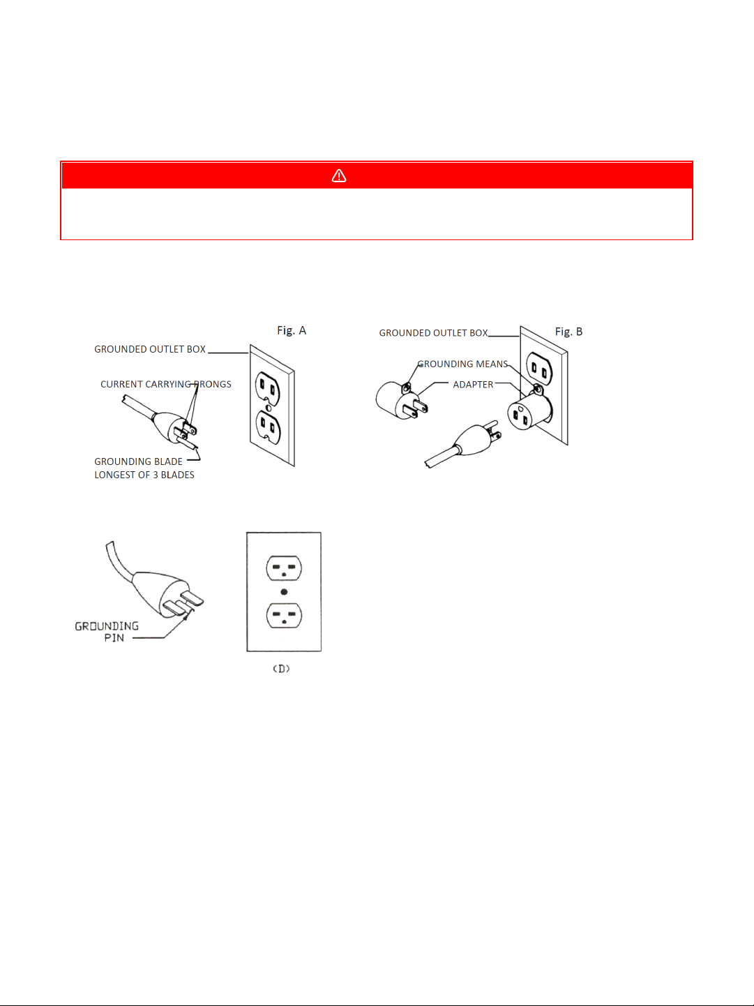
Grounding Methods Provided by CSA Group. (A) Receptacle with nominal rating less than
150 volts. (B) 150 volt receptacle without grounding pin fitted with adapter. (C) 150-250
volt receptacle.
Fig C
Grounding Methods
DANGER!
1. All grounded, cord-connected machines:
In the event of a malfunction or breakdown, grounding provides a path of least resistance for electric
current to reduce the risk of electric shock. This tool is equipped with an electric cord having an equipmentgrounding conductor and a grounding plug. The plug must be plugged into a matching outlet that is properly
installed and grounded in accordance with all local codes and ordinances.
Do not modify the plug provided - if it will not fit the outlet, have the proper outlet installed by a qualified
electrician.
Improper connection of the equipment-grounding conductor can result in a risk of electric shock. The
conductor with insulation having an outer surface that is green with or without yellow stripes is the
equipment-grounding conductor. If repair or replacement of the electric cord or plug is necessary, do not
connect the equipment-grounding conductor to a live terminal.
Page 11

11PXl16 Sheartec:II Planer \ Electrical Safety
Check with a qualified electrician or service personnel if the grounding instructions are not completely
understood, or if in doubt as to whether the tool is properly grounded.
Use only 3-wire extension cords that have 3-prong grounding plugs and 3 pole receptacles that accept the
tool's plug.
Repair or replace damaged or worn cord immediately.
2. Grounded, cord-connected machines intended for use on a supply
circuit having a nominal rating less than 150 volts:
This tool is intended for use on a circuit that has an outlet that looks like the one illustrated in Fig. A. The
tool has a grounding plug that looks like the plug illustrated in Fig A. A temporary adapter, which looks like
the adapter illustrated in Fig B may be used to connect this plug to a 2 pole receptacle as shown in Fig B if a
properly grounded outlet is not available. The temporary adapter should be used only until a properly
grounded outlet can be installed by a qualified electrician. This adapter is not permitted in Canada. The
green-colored rigid ear, lug, and the like, extending from the adapter must be connected to a permanent
ground such as a properly grounded outlet box.
3. Grounded, cord-connected tools intended for use on a supply circuit
having a nominal rating between 150 – 250 volts, inclusive:
This tool is intended for use on a circuit that has an outlet that looks like the one illustrated in Fig C. The
tool has a grounding plug that looks like the plug illustrated in Fig C. Make sure the tool is connected to an
outlet having the same configuration as the plug. No adapter is available or should be used with this tool. If
the tool must be reconnected for use on a different type of electric circuit, the reconnection should be made
by qualified service personnel; and after reconnection, the tool should comply with all local codes and
ordinances.
Page 12

12 PXl16 Sheartec:II Planer \ Electrical Safety
MINIMUM GAUGE EXTENSION CORD 120V
RECOMMENDED SIZES FOR USE WITH STATIONARY ELECTRIC MACHINES
Ampere
Rating
Volts
Total Length of
Cord in Feet
Gauge of Extension Cord
0-6
0-6
0-6
0-6
120
120
120
120
up to 25
25-50
50-100
100-150
18 AWG
16 AWG
16 AWG
14 AWG
6-10
6-10
6-10
6-10
120
120
120
120
up to 25
25-50
50-100
100-150
18 AWG
16 AWG
14 AWG
12 AWG
10-12
10-12
10-12
10-12
120
120
120
120
up to 25
25-50
50-100
100-150
16 AWG
16 AWG
14 AWG
12 AWG
12-16
12-16
12-16
120
120
120
up to 25
25-50
14 AWG
12 AWG
GREATER THAN 50 FEET NOT RECOMMENDED
MINIMUM GAUGE EXTENSION CORD 240V
RECOMMENDED SIZES FOR USE WITH STATIONARY ELECTRIC MACHINES
Ampere
Rating
Volts
Total Length of
Cord in Feet
Gauge of Extension Cord
0-6
0-6
0-6
0-6
240
240
240
240
up to 50
50-100
100-200
200-300
18 AWG
16 AWG
16 AWG
14 AWG
6-10
6-10
6-10
6-10
240
240
240
240
up to 50
50-100
100-200
200-300
18 AWG
16 AWG
14 AWG
12 AWG
10-12
10-12
10-12
10-12
240
240
240
240
up to 50
50-100
100-200
200-300
16 AWG
16 AWG
14 AWG
12 AWG
12-16
12-16
12-16
240
240
240
up to 50
50-100
14 AWG
12 AWG
GREATER THAN 100 FEET NOT RECOMMENDED
Extension Cords
Use proper extension cords. Make sure your extension cord is in good condition and is a 3wire extension cord which has a 3-prong grounding type plug and matching receptacle which will accept the
machine’s plug. When using an extension cord, be sure to use one heavy enough to carry the current of the
machine. An undersized cord will cause a drop in line voltage, resulting in loss of power and overheating. If
in doubt, use the next heavier gauge. The smaller the gauge number, the heavier the cord.
Page 13

Specifications
MPLANPX16-0130
VOLT HP MOTOR AMP. RECOM.
SIZE BRKR.
230V 5HP 1PHASE 60HZ/23AMP.
CSA
YES
BED SIZE
16 X 21-1/2"
PULL-OUT EXTENSION
4"
WHEELS BUILT-IN
OPTIONAL
MAX. DEPTH OF CUT
1/4"
MAX. STOCK THICKNESS
8"
MIN. STOCK THICKNESS
1/4"
MIN. STOCK LENGTH
8"
MAX. STOCK WIDTH
16"
FEED SPEED
16 & 28 FPM
DUST PORT DIAMETER
4" LEFT AND RIGHT
CUTTERHEAD RPM
5000
CUTTERHEAD DIAMETER
3"
CUTTERHEAD INSERT #
108 X 4-SIDED CARBIDE, 6 ROW
THICKNESS READOUT
WIXEY DRO
DIMENSIONS SET UP APPROX.
33" X 36"
DIMENSIONS SHIPPING
38"X30"X46"
NET/SHIP WEIGHT # OF
BOXES
LBS. 493/597 1BOX
PXl16 Sheartec:II Planer
13PXl16 Sheartec:II Planer \ Specifications
Page 14
14 PXl16 Sheartec:II Planer \ Machine Overview
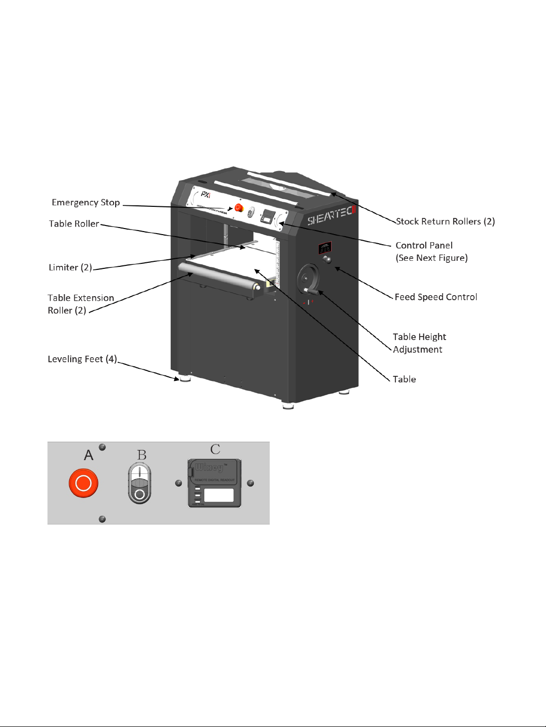
Figure 6: Main Components of PX16
A. Emergency Stop (E-STOP); stops all functions of
machine, however, power continues to machine.
NOTICE! To reset E-STOP, rotate switch
clockwise until the button “pops” out.
B. B. ON/OFF Switch; Starts and Stops rotation of
cutterhead. NOTICE! Will not work if the ESTOP
is engaged or if the Hood is open.
C. Digital Read Out (DRO); Thickness display
Machine Overview
PXl16 Sheartec:II Planer
The Limiter (Fig. 6) acts as a stop to prevent the cutterhead from contacting the table and to prevent stock
from sliding past the edge of the cutterhead.
Table Rollers
The Rollers act as a stop to reduce the chance of stock from sliding past the edge of the cutterhead or table.
Limiter
Page 15

Extension Rollers
AS WITH ALL GEAR BOX SHIFTERS, IT IS VERY IMPORTANT TO ONLY CHANGE SPEEDS WHEN THE MACHINE IS
RUNNING.
Adjustable rollers that extend for increased workpiece support.
Feed Speed Selector
CAUTION!
The feed speed selector offers two feed speeds, 16 FPM & 28 FPM. Move lever (push/pull) until it locks in
place. The middle setting is neutral.
Thickness Gauge
The top of the planer is a Wixey thickness gauge. Material thickness can be quickly identified by placing it
on edge into the various gauges and reading the corresponding measurement.
Stock Return Rollers
Allows users to return stock back to feed zone quickly and safely with less strain on workers.
15PXl16 Sheartec:II Planer \ Machine Overview
Page 16

16 PXl16 Sheartec:II Planer \ Setup
NOTICE!
·
ALL SHIPPING DAMAGE MUST BE NOTED UPON DELIVERY AND SIGNED BY THE OWNER AND THE DELIVERY DRIVER.
IF YOU FIND ANY DAMAGED ITEMS IN YOUR PACKAGE, YOU MUST CONTACT LAGUNA TOOLS TO FILE A COMPLAINT.
IN ORDER TO RETURN DAMAGED GOODS UNDER THE LIMITED WARRANTY TO LAGUNA TOOLS, INC., YOU MUST HAVE
THE ORIGINAL PACKAGING. ALL CLAIMS OF LOSS OR DAMAGED GOODS MUST BE REPORTED TO LAGUNA TOOLS
WITHIN 24 HOURS OF DELIVERY. PLEASE CONTACT THE LAGUNA TOOLS, INC. CUSTOMER SERVICE DEPARTMENT TO
MAKE CLAIMS FOR ANY DAMAGED ITEMS/PARTS.
·
IT IS PROBABLE THAT YOU WILL FIND SAWDUST WITHIN YOUR MACHINE. THIS IS BECAUSE THE MACHINE HAS
BEEN TESTED PRIOR TO SHIPMENT FROM THE FACTORY AND OR LAGUNA TOOLS. WE TEST MACHINES PRIOR TO
SHIPPING TO CUSTOMERS, BUT MOVEMENT CAN TAKE PLACE DURING TRANSPORTATION. SOME ADJUSTMENTS
MAY HAVE TO BE UNDERTAKEN BY THE CUSTOMER. THESE ADJUSTMENTS ARE COVERED IN THE VARIOUS
SECTIONS OF THIS MANUAL.
Setup
Setup Overview (MUST READ)
When setting up your PXl16 Sheartec:II Planer, please take a moment to read this overview prior to
starting.
The machine comes mostly assembled. You will have to assemble the leveling feet, the dust chute, and
calibrate the height.
After Setup, There may be a few adjustment to be made. All of these adjustments are done prior to shipping
the machine, but if additional adjustments are required, please follow the adjustment guides.
If you have any doubt about the described procedure, seek professional assistance. Do not
attempt any procedure that you feel is unsafe, or that you do not have the physical capability of achieving.
Placement & Unboxing
Your Machine will likely be delivered by a third party delivery service. Before unpacking your new machine,
first inspect the packaging, the invoice, and the shipping documents supplied by the driver. When unpacking
your machine, separate all enclosed items from the packing materials and inspect them for damages.
Ensure that there is no visible damage to either the packaging or the machine BEFORE the driver leaves.
Save all packaging materials until you are satisfied with the machine and/or have resolved any issues
concerning any missing or damaged items.
Placement
Before you remove your machine from the packaging, select the area where you will use your machine.
There are no hard and fast rules for its location, but below are a few guidelines:
1. There should be sufficient area at the front of the machine to allow you to work on it comfortably.
2. There should be sufficient area at the back of the machine to allow access for adjustments and
maintenance to be conducted.
3. Adequate lighting. The better the lighting the more accurately and safely you will be able to work.
4. Solid floor. You should select a solid flat floor, preferably one made of concrete or something similar.
Page 17
5. Locate it close to a power source and dust collection.
·
THE MACHINE WEIGHS 597 LBS (270KG). ENSURE THAT YOU HAVE ENOUGH PEOPLE TO DO THE JOB SAFELY.
·
IF YOU HAVE ANY DOUBT ABOUT THE DESCRIBED PROCEDURE, SEEK PROFESSIONAL ASSISTANCE. DO NOT
ATTEMPT ANY PROCEDURE THAT YOU FEEL IS UNSAFE, OR THAT YOU DO NOT HAVE THE PHYSICAL CAPABILITY OF
ACHIEVING.
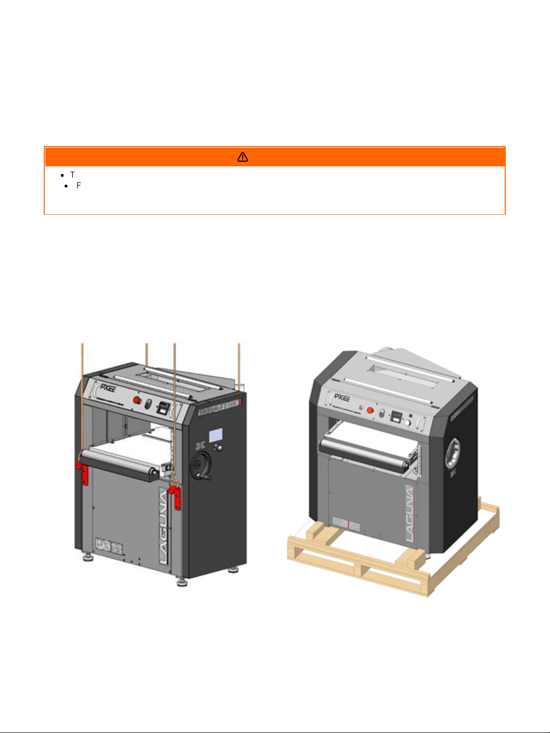
FIGURE 1: LIFTING PLANER WITH HOOKS AND HARNESS
FIGURE 2: PALLET
6. Allow an area for the storage of blanks, finished products and tools.
Unboxing
WARNING!
This step requires a forklift. The PX16 is heavy, be careful when lifting and handling it! Failure to comply
may cause serious injury and/or damage to the machine and/or property! Use a forklift to remove PX16
from pallet and place on floor.
NOTE: Another option to remove the planer from the pallet is to attach the included hooks to frame of
machine at each of the four corners (Fig. 1). The hooks and bolts are included in the hardware kit. The
machine can then be lifted with a harness and forklift. Remove and save hooks for later movement
scenarios.
17PXl16 Sheartec:II Planer \ Setup Placement & Unboxing
Page 18
18 PXl16 Sheartec:II Planer \ Setup Inventory List
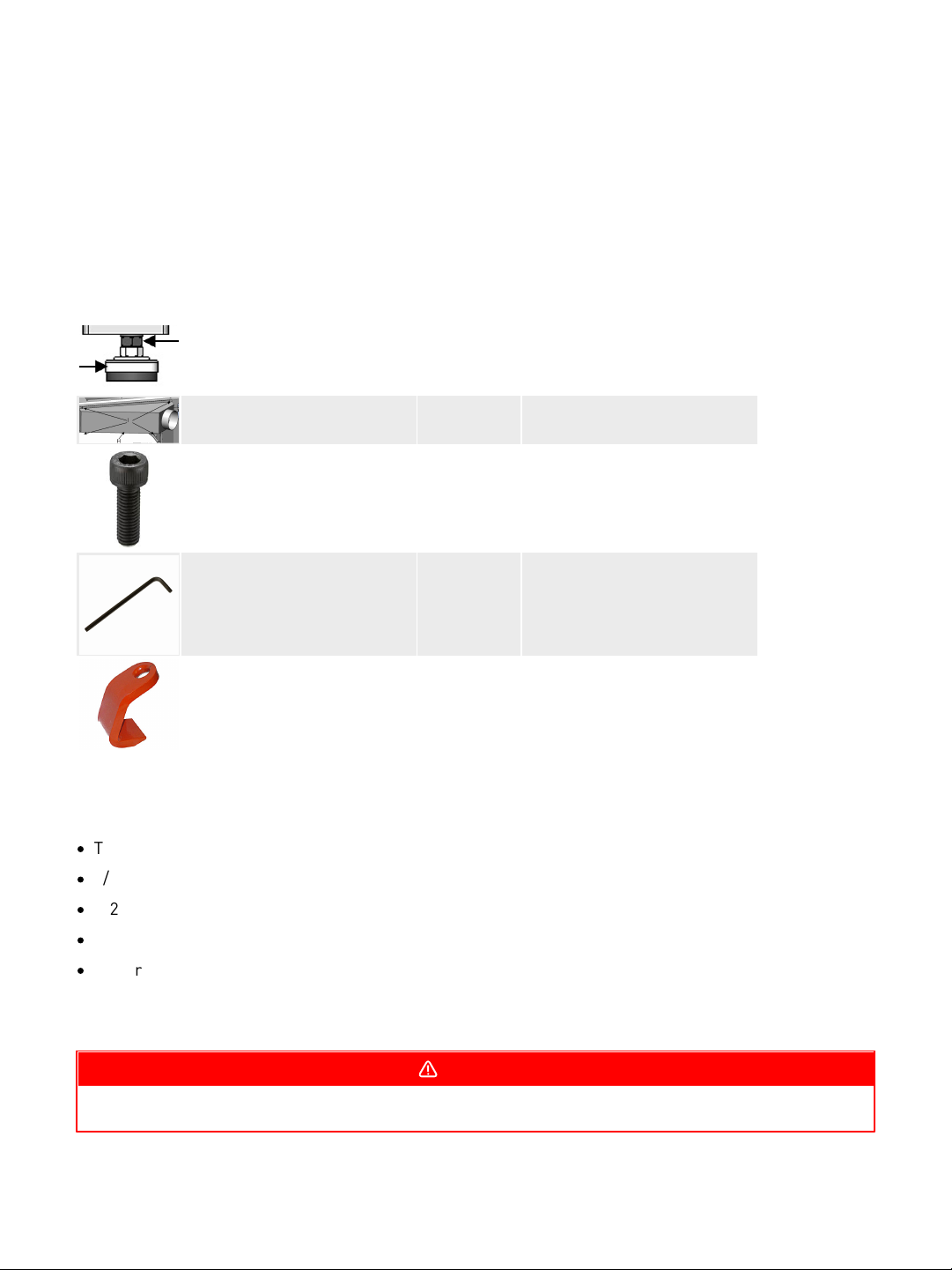
REF
Description
Q
Packaging
Leveling Feet with Hardware
4
On Paller
Dust Chute
1
In Bubble Wrap
Hex Head Screws M6x10
4
In Bubble Wrap
T25 Torx Wrenches
2
In Bubble Wrap
Lifting hooks & hardware
4
In Bubble Wrap
FOR YOUR OWN SAFETY, DO NOT CONNECT THE MACHINE TO THE POWER SOURCE UNTIL THE MACHINE IS
COMPLETELY ASSEMBLED! PLEASE ALSO MAKE SURE THAT YOU READ AND UNDERSTAND THE ENTIRE MANUAL.
Inventory List
The following depicts items shipped with your machine. Before assembling, ensure that you have received
all parts shown below. Machine parts should arrive sealed in plastic bags. Remove parts from plastic bags
before laying them out to inventory them.
Tools/items Required: Assembly & Adjustment
·
T-25 Torx wrench, included
·
9/16” wrench
·
1/2” wrench
·
5mm hex wrench
·
Power Cord and Plug (unless hard wiring into a disconnect)
DANGER!
Page 19
Assembling
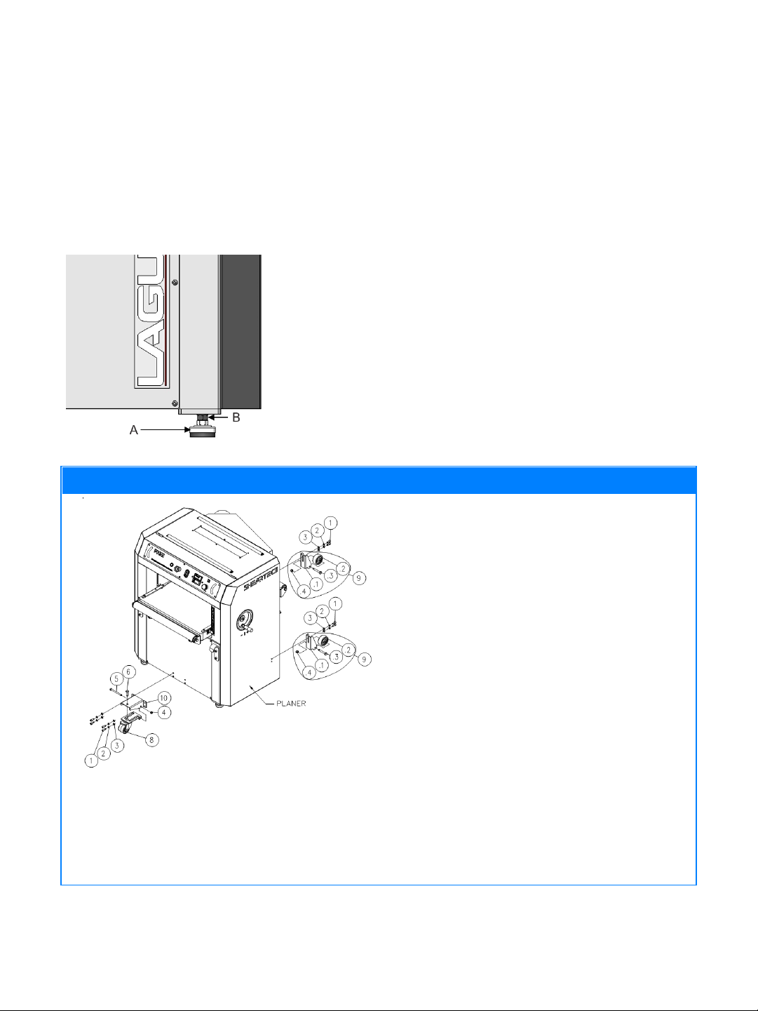
FIGURE 3: LEVELING FEET
(OPTIONAL) If Installing Unverisal Casters
FIGURE 28: CASTER INSTALLATION
Installing universal caster set (Fig. 28):
1. Raise and block planer for attaching caster set.
2. Assemble swivel caster into swivel caster
bracket (straight bracket) by placing bolt #5
through bracket and caster and securing with
lock nut #4. Then place bolt #6 down through
bracket into caster mount.
3. Attach swivel caster to front (infeed) center of
frame with four bolts #1, washers #2 and nuts
#3. Tighten all four bolts.
4. Assemble caster (wheel) #.2 to bracket #.1
using bolt #.3 and nut #.4. Repeat this process
for second caster.
5. Attach caster assembly #9 to rear (outfeed) side
of frame using two bolts #1, two washers #2 and
two nuts #3. Repeat process for both casters.
Tighten all four bolts.
6. Carefully remove blocks with planer resting on
casters.
Machine Preparation and Setup:
1. Level machine using the four leveling feet on each of the four corners. Lock leveling feet into position
with the nut on the leveling foot stud (Fig. 3).
19PXl16 Sheartec:II Planer \ Setup Assembling
Page 20
20 PXl16 Sheartec:II Planer \ Setup Assembling
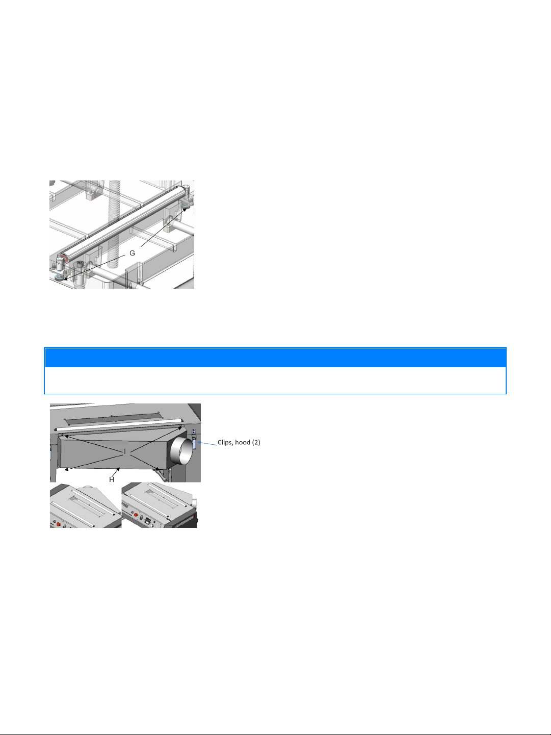
FIGURE 4: TABLE ROLLER
ADJUSTMENT
NOTICE!
MAKE SURE THE DUST COLLECTION SYSTEM HAS SUFFICIENT CAPACITY AND CFM FOR THIS PLANER. ALWAYS TURN
ON THE DUST COLLECTOR BEFORE PLANNING.
FIGURE 5: DUST CHUTE & HOOD CLIPS
2. 2. Clean all rust protected surfaces with a commercial de-greaser. DO NOT use acetone, gasoline,
lacquer thinner or any type of cleaner that could damage paint. Coat cleaned surfaces with WD-40® or
20W machine oil.
3. Table Roller adjustment: Turn the knobs (Fig. 4, G) to move the table roller up or down to the desired
position. NOTICE! The roller is typically set higher when planing rough stock. When planing smooth
stock, the roller should be set slightly above, or flush with the table.
4. The dust chute can be attached with the port facing either to the right or left. To attach use four included
screws (Fig. 5, H) to mount to the rear (outfeed) side of the planer head.
Opening Hood
1. Release the 2 Clips (Fig. 5) on each side of the hood.
2. Remove the two lower screws holding the dust chute in place (Fig. 5)
3. Raise hood until automatic latch secures hood in open position
4. To close, press IN automatic latch while lowering hood
Page 21
Power Supply Circuit Requirements
IN ALL CASES, MAKE CERTAIN THE RECEPTACLE IN QUESTION IS PROPERLY GROUNDED. IF YOU ARE NOT SURE,
HAVE A QUALIFIED ELECTRICIAN CHECK THE RECEPTACLE.
WHEN COMPLETED, THE MACHINE MUST CONFORM TO THE NATIONAL ELECTRIC CODE AND ALL LOCAL CODES AND
ORDINANCES.
DISCONNECT POWER SUPPLY TO PLANER BEFORE CONTINUING! ONLY CONNECT POWER WHEN REQUIRED.
The power source circuit for your machine must be grounded and rated for the amperage given below.
Never replace a circuit breaker on an existing circuit with one of higher amperage without consulting a
qualified electrician to ensure compliance with wiring codes. If you are unsure about the wiring codes in
your area or you plan to connect your machine to a shared circuit, consult a qualified electrician.
Circuit Size (208-230V, Single Phase) ........30 Amp (minimum)
DANGER!
Motor Specifications
The typical main motor is 5 HP and is typically wired for 220 Volt, Single Phase, 60 HZ, AC current. Confirm
your motor electrical configuration before connecting power! Before connecting the machine to the power
source, make sure the starter and switches are in the "OFF" position. Cord and “plug” are NOT included.
These must be installed by a qualified technician/electrician to local codes.
NOTICE! A “plug” and cord are NOT included and must be installed by a qualified technician/electrician or
the power cable connected (hard wired) to an appropriate disconnect according to local codes.
21PXl16 Sheartec:II Planer \ Setup Assembling
WARNING
Connecting Power (See also wiring diagram page 33)
1. Remove screws securing cover to connection box.
2. Insert power cable through strain relief, tighten cinch nut and attach wires to terminals.
3. Re-install the connection box cover, see page 33 for wiring diagram.
WARNING
Page 22
22 PXl16 Sheartec:II Planer \ Setup Assembling
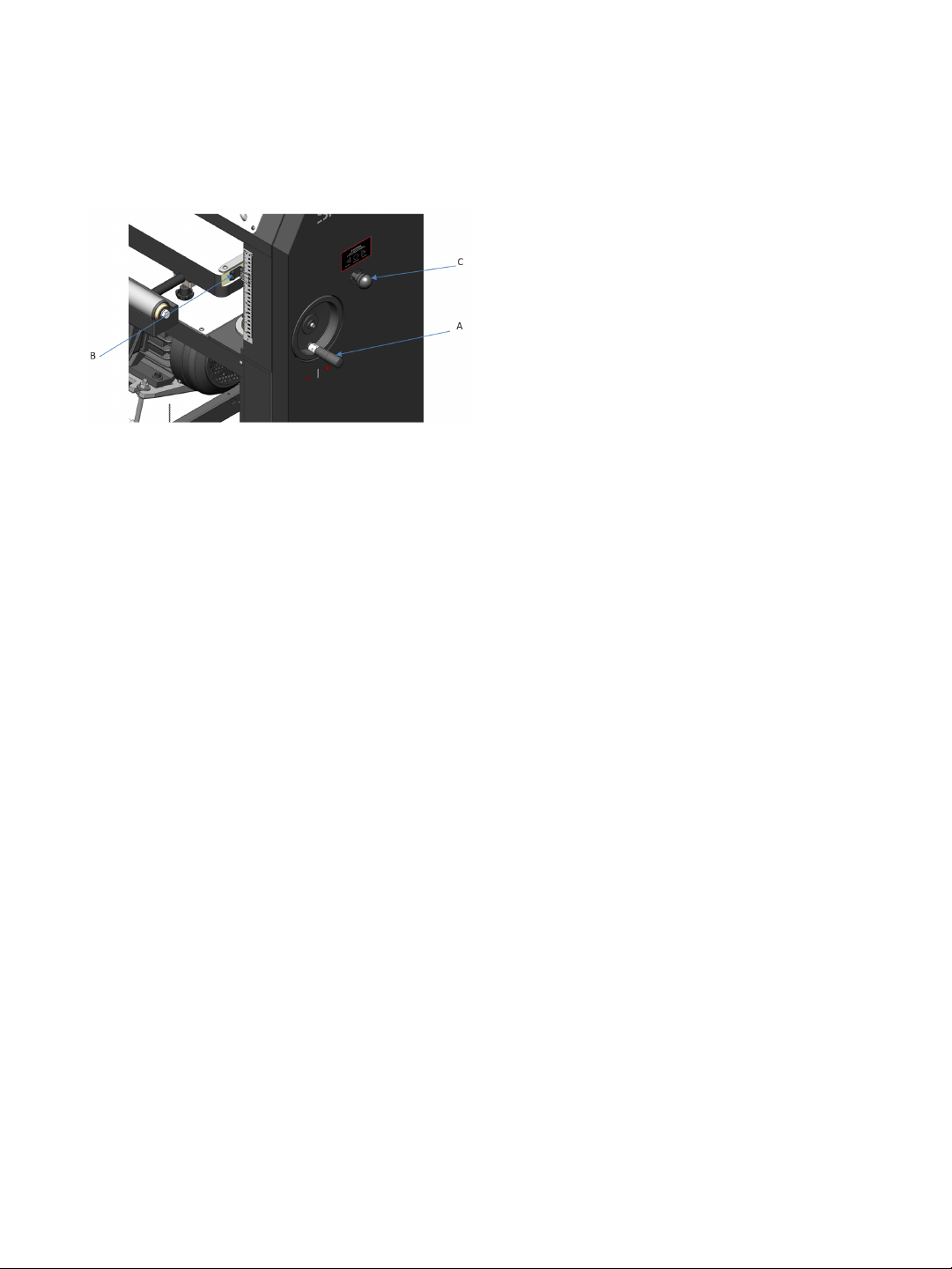
FIGURE 8: THICKNESS SCALE CALIBRATION
NOTICE! The following procedures describe the
use of a “calibrating board”. It is a piece of
hardwood which has been surfaced on one side with
a jointer, drum sander or wide belt sander.
1. With the planer OFF, the cutter head not rotating
and power disconnected, place the Calibrating
Board on the table, with the previously
machined (flat) face “down”, and slide under the
cutterhead.
Calibrating the Thickness Scale
1. Make sure the Carriage Lock is unlocked (UP position).
2. Use the Table Height Adjustment handle (Fig. 8, A) to raise the table until the infeed roller is
approximately 1/16” above the calibrating board.
3. Remove the calibrating board from the planer.
4. Connect power to the planer and turn ON.
5. Turn the height adjustment handle clockwise, one complete revolution, to lower the carriage and run the
calibrating board (previously machined face “down”) through the planer. Lock (“down” position) the
carriage lock.
6. Repeat Step 5 until the planer removes the entire top surface of the calibrating board. NOTICE! Drawing
pencil marks across the width of the top of the calibrating board in several locations can make it easier
to determine when the entire surface has been planned.
7. Measure the thickness of the calibrating board with a caliper.
8. Loosen the two screws of the Thickness Scale pointer and adjust the pointer (Fig. 8, B) until it
corresponds to the measured thickness and tighten the screws.
Page 23
Calibrating the DRO (Digital Read Out)
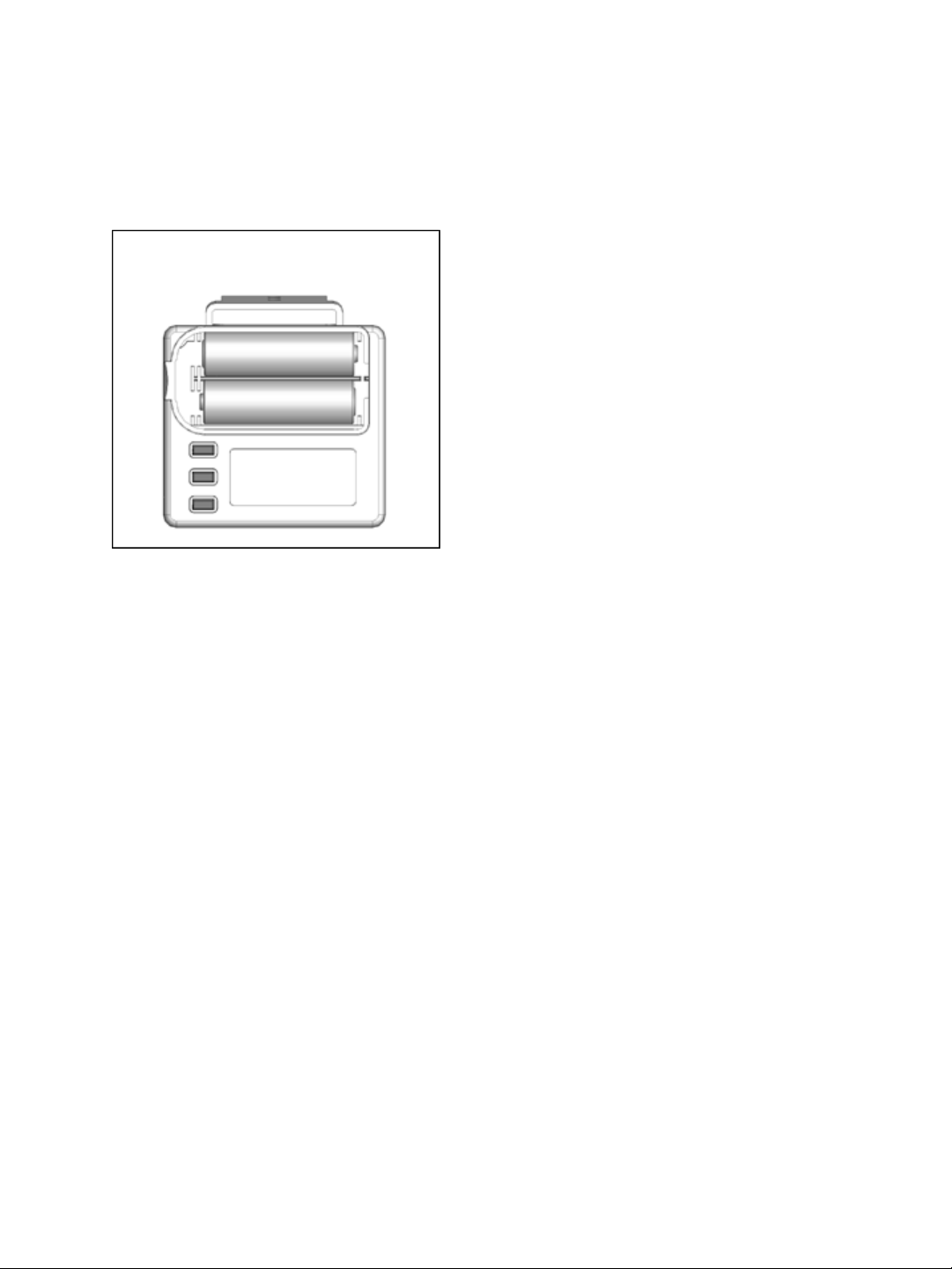
FIGURE 9: DRO BATTERIES
1. Remove the battery cover of the DRO and install 2 AAA batteries.
23PXl16 Sheartec:II Planer \ Setup Assembling
DRO Button Reference and Use
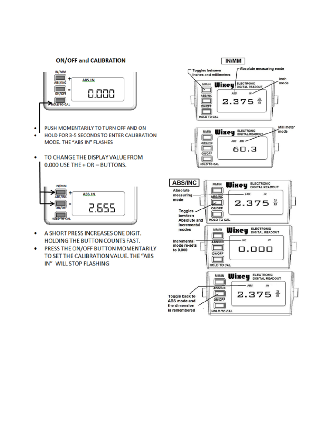
It is helpful to familiarize these buttons and their purpose with the Wixey™ DRO
Page 24
24 PXl16 Sheartec:II Planer \ Setup Assembling
FIGURES 10-12: DRO ADJUSTMENT
Page 25

Operation
PLACE THE PLANER ON A SECURE AND STABLE SURFACE FOR OPERATION. CLAMP OR BOLT THE PLANER INTO
POSITION.
Helpful Tips
• PLANERS WORK BEST IF ONE FACE OF STOCK IS FLAT. IF NOT, FLATTEN WITH A JOINTER OR DRUM SANDER.
• IF NOT POSSIBLE TO FLATTEN ONE FACE, PROCESS CUPPED MATERIAL WITH THE CUP “UP” SO THE MATERIAL IS
STABLE ON THE PLANER BED.
• IF MATERIAL IS SEVERELY CUPPED, ANOTHER OPTION IS TO RIP THE MATERIAL, PLANE IT AND GLUE IT BACK
TOGETHER.
• PLANE WITH THE DIRECTION OF GRAIN TO REDUCE TEAR-OUT AND PROVIDE THE BEST SURFACE FINISH.
CAUTION!
1. Establish the proper depth of cut (typically less than 1/16”), using either the DRO or scale.
2. Pull out and lock each extension roller to support long stock
3. Start dust collection.
4. Start planer.
5. Adjust feed speed (Fig. 8, C) to desired speed (16 or 28 FPM), while planer is running.
6. Feed stock into planer, maintain control and support of stock until the stock is securely feeding through
planer.
7. Reposition yourself to the outfeed side of planer and control and support stock until it has exited the
outfeed roller.
25PXl16 Sheartec:II Planer \ Operation
Page 26

26 PXl16 Sheartec:II Planer \ Maintenance
Maintenance
General
Keep your machine clean. At the end of each day, clean the machine. Wood contains moisture, and if
sawdust or wood chips are not removed they will cause rust.
In general, we recommend that you only use a Teflon-based lubricant on the planer. Regular oil attracts
dust and dirt. Teflon lubricant tends to dry and has less of a tendency to accumulate dirt and sawdust.
Periodically check that all nuts and bolts are tight.
Routine Inspections
It is a good idea to routinely inspect any quality woodworking tool in order to keep it in optimum condition.
This includes inspecting all hardware for tightness, ensuring the filter is clean, and cleaning debris and
grime from any surfaces and moving parts. In addition, make sure to:
·
Clean out-feed rollers and table with a non- flammable solvent to remove pitch, gum and other
unwanted build-up.
·
Periodically clean the inside of the machine for dust control.
·
Keep pulleys and belts free from dirt, dust, oil and grease.
·
Replace worn belts as needed.
·
Replace or rotate worn knives.
·
There is one limit switch on the planer that triggers if the hood is opened. Keep it clean and blown out with
an air hose.
Page 27
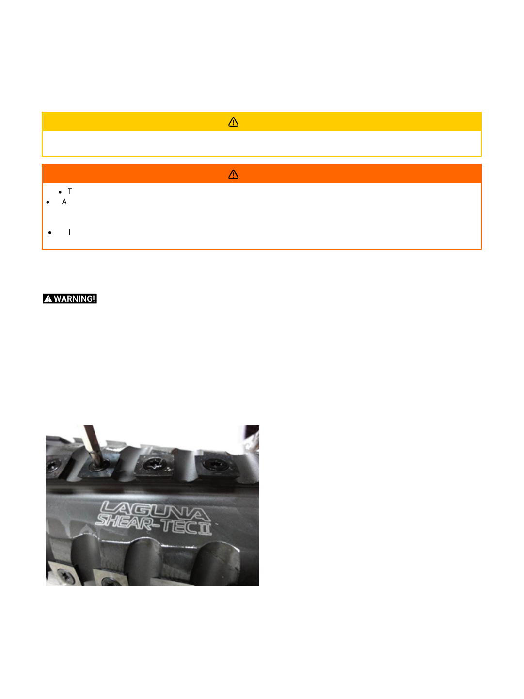
Sheartec II Knife rotation/replacement
KNIFE INSERTS ARE DANGEROUSLY SHARP. USE EXTREME CAUTION WHEN INSPECTING, REMOVING, OR REPLACING
KNIFE INSERTS.
·
TURN PLANER OFF AND DISCONNECT POWER BEFORE PERFORMING ANY MAINTENANCE OR ADJUSTMENTS!
·
MAKE SURE ALL KNIFE INSERT SCREWS ARE TIGHTENED SECURELY. LOOSE INSERTS CAN BE PROPELLED AT HIGH
SPEED FROM A ROTATING CUTTERHEAD, CAUSING INJURY.
TORQUE EACH SCREW TO 52-60 IN/LBS.
·
KNIVES ARE EXTREMELY SHARP. BE VERY CAREFUL WHEN HANDLING KNIVES. FAILURE TO COMPLY MAY CAUSE
SERIOUS INJURY
FIGURE 13: CUTTERHEAD
CAUTION!
WARNING
The knife inserts on the Planer are four-sided. When dull, remove each knife, rotate it 90° for a fresh edge,
and re-install it. No further adjustment is necessary. Use a Torx wrench (T25) to remove the knife insert
screw. Use a second Torx wrench to hold the cutterhead (from rotating) in position (in another screw).
DO NOT USE YOUR HAND TO HOLD THE CUTTERHEAD! See Fig. 13.
It is advisable to rotate all inserts at the same time to maintain consistent cutting. However, if one or more
knife inserts develops a nick, rotate only those inserts that are affected. Each knife insert has an etched
reference mark so you can keep track of the rotation. Torque each screw to 52-60 in/lbs.
27PXl16 Sheartec:II Planer \ Maintenance
IMPORTANT! When removing or rotating inserts, clean sawdust from the screw, the insert, and the
cutterhead platform. Dust accumulation between these elements can prevent the insert from seating
properly, and may affect the quality of the cut.
Before installing each screw, lightly coat the screw threads with machine oil and wipe off any excess.
Securely tighten each screw which holds the knife inserts before operating the jointer!
Page 28
28 PXl16 Sheartec:II Planer \ Maintenance
·
TURN PLANER OFF AND DISCONNECT POWER BEFORE PERFORMING ANY MAINTENANCE OR ADJUSTMENTS!
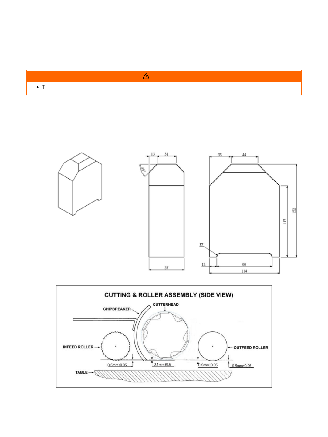
FIGURES 14 & 15: SET-UP-BLOCK
FIGURE 16: CUTTERHEAD
Conveying Rollers
WARNING
MAINTENANCE: Keep rollers clean to help prevent slippage of material. Be careful not to contact
cutterhead knives as they are very sharp!
ADJUSTMENTS: The planer comes set-up from the factory and typically will not need adjustment. If it is
determined adjustment is needed, follow these steps for setting the infeed roller, chip breaker, pressure bar
and outfeed roller; 1. Make a hardwood block to the specifications in drawings (Figures 14 & 15). Use this
wood gauge along with 0.02” feeler gauge to set the planer up as shown in Fig. 16.
Page 29
Anti-Kickback Fingers
·
TURN PLANER OFF AND DISCONNECT POWER BEFORE PERFORMING ANY MAINTENANCE OR ADJUSTMENTS!
Anti-kickback fingers help prevent stock from being
kicked out of the machine towards the user. Keep
the fingers clean and free from sawdust, pitch gum,
etc., so they operate smoothly.
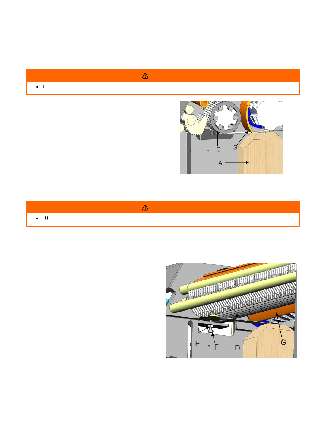
FIG. 17: FINGER ADJUSTMENT
·
TURN PLANER OFF AND DISCONNECT POWER BEFORE PERFORMING ANY MAINTENANCE OR ADJUSTMENTS!
1. Place a hard wood gauge (Fig.17, A) under a
knife in cutterhead (Fig.17, B). Place a 0.02”
feeler gauge (Fig.17, C) on top of wood block
and raise table until feeler gauge contacts the
knife in its lowest position.
2. Remove feeler gauge and place wood block
under the left side of infeed roller (Fig.18, D).
The top of wood gauge should just contact the
infeed roller. If it doesn’t, loosen jam nut (Fig.
18, E) and turn the adjusting screw (Fig.18, F) to
raise, or lower the infeed roller until it contacts
wood gauge then tighten the nut (E). Repeat for
opposite side of the infeed roller.
FIG. 18: INFEED ROLLER ADJUSTMENT
Adjustment of Infeed Roller
29PXl16 Sheartec:II Planer \ Maintenance
WARNING
The in-feed roller should be set 0.02” below the lowest point of knife. Make sure the knives are set
properly see the “Setting / Changing Knives” section prior to making any adjustments.
1. Disconnect machine from power source.
WARNING
Page 30
30 PXl16 Sheartec:II Planer \ Maintenance
·
TURN PLANER OFF AND DISCONNECT POWER BEFORE PERFORMING ANY MAINTENANCE OR ADJUSTMENTS!
1. Disconnect machine from power source.
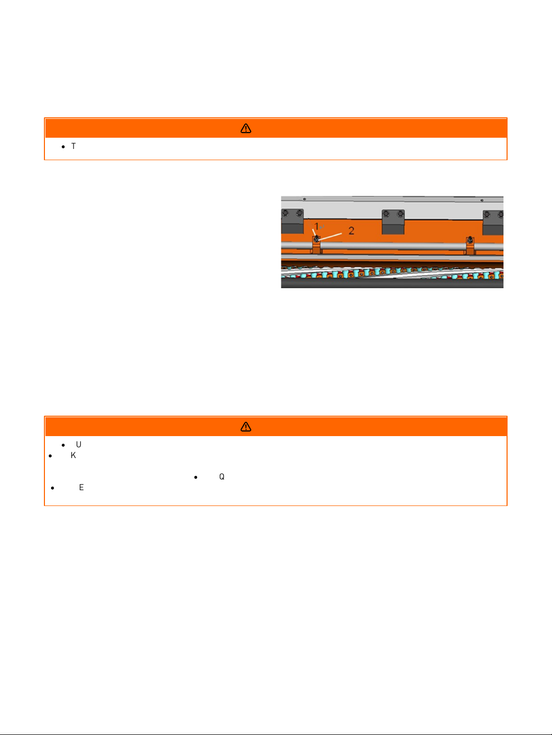
2. Loosen screw (Fig. 19, 1) and nut (Fig.19, 2) turn
the screw to the right so that the pressure bar
moves upward. Place gauge block and 0.2m/m
thickness gauge (Fig.17, A) under the
cutterhead.
3. Place gauge block under pressure bar.
4. Make pressure bar touch the top of the gauge
block.
5. Finally, tighten the screw and replace the nut.
FIG. 19: PRESSURE BAR ADJUSTMENT
·
TURN PLANER OFF AND DISCONNECT POWER BEFORE PERFORMING ANY MAINTENANCE OR ADJUSTMENTS!
·
MAKE SURE ALL KNIFE INSERT SCREWS ARE TIGHTENED SECURELY. LOOSE INSERTS CAN BE PROPELLED AT HIGH
SPEED FROM A ROTATING CUTTERHEAD, CAUSING INJURY.
·
TORQUE EACH SCREW TO 52-60 IN/LBS.
·
KNIVES ARE EXTREMELY SHARP. BE VERY CAREFUL WHEN HANDLING KNIVES. FAILURE TO COMPLY MAY CAUSE
SERIOUS INJURY
Adjustment of Pressure Bar
WARNING
The pressure bar should be set even with the lowest point of knife. Make sure the knives are set properly
see the “Setting / Changing Knives” section prior to making any adjustments.
Adjustment of Out-feed Roller
WARNING
The out-feed roller should be set 0.02” below the lowest point of knife. Make sure the knives are set
properly see the “Setting / Changing Knives” section prior to making any adjustments.
Page 31
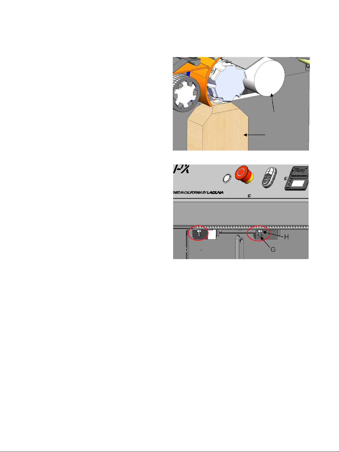
1. Disconnect machine from power source.
2. Place a hard wood gauge (Fig.17, A) under a
knife in the cutterhead. Place a 0.02” feeler
gauge (Fig. 17, B) on top of wood block and
raise table until the gauge contacts the knife in
its lowest position.
3. Remove feeler gauge and place wood block
4. (Fig.20, E) under the left side of outfeed roller
(Fig. 20, F). The top of wood gauge should just
contact the outfeed roller. If it doesn’t, loosen
jam nut (Fig. 21, H) and turn the adjusting screw
(Fig. 21, G) to raise, or lower the out-feed roller
until it contacts wood gauge.
The cutterhead is set-up with the same relationship
to the infeed roller, pressure bar and outfeed roller.
The planer comes set up from the factory and
shouldn’t need any adjustment.
If adjustment is necessary, follow the steps for
setting the in-feed roller, chipbreaker, pressure bar
and outfeed roller in relation to the helical
cutterhead.
When it is time to rotate the knives ALL knives
should be rotated at the same time. This is the same
when replacing carbide knives ALL knives must be
replaced at the same time. Mark the knives with a
marker to identify which knives have been rotated.
You can rotate the knives three times before
replacing. Use a Torx wrench to rotate or remove
knives. Torque each knife screw to 52-60 in/lbs.
FIGURE 20: OUTFEED ROLLER ADJUSTMENT
FIGURE 21: OUTFEED ROLLER ADJUSTMENT
31PXl16 Sheartec:II Planer \ Maintenance
Page 32
32 PXl16 Sheartec:II Planer \ Maintenance
·
TURN PLANER OFF AND DISCONNECT POWER BEFORE PERFORMING ANY MAINTENANCE OR ADJUSTMENTS!
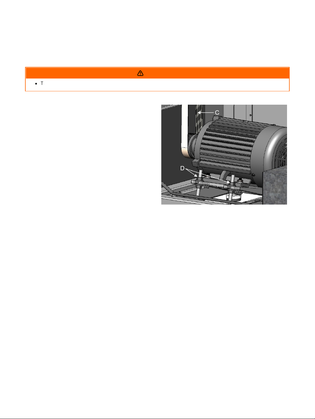
1. Disconnect machine from power source.
2. Open lower rear, and lower left-hand side
panels. Loosen and tighten four adjustment
nuts (Fig. 22, D) to move motor plate up, or
down to increase, or decrease belt tension.
3. Tighten nuts against motor plate after
adjustment is made.
4. Belts are tensioned properly when moderate
finger pressure can deflect the v-belts about a
1/4"-1/2” midway between the pulleys.
FIGURE 22: POLY-V-BELT ADJUSTMENT
Poly-V-Belt Adjustment
WARNING
Poly-V-belt (Fig. 22, D) tension has been set at the factory. If the belt has stretched and needs adjustment.
Page 33
Adjusting Table Rollers
·
TURN PLANER OFF AND DISCONNECT POWER BEFORE PERFORMING ANY MAINTENANCE OR ADJUSTMENTS!
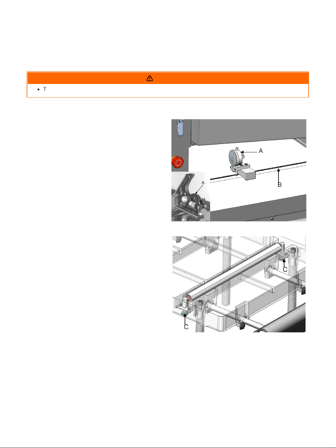
1. Lay a gauge or straight edge (Fig. 23, A) on the
table across the roller (Fig. 23, B).
2. Raise the rollers until it contacts the straight
edge and lock the handle. The pointer should be
set at “0”. If not adjust the pointer to read zero.
Note: Spin the roller by hand to know when
roller makes contact with the straight edge.
3. Move straight edge to the opposite side of bed
roller and check to see that the roller just
contacts straight edge. If not turn the knob (Fig.
24, C) under the table to raise or lower the bed
roller until it just contacts the straight edge.
FIGURE 23: TABLE ROLLER ADJUSTMENT
FIGURE 24: TABLE ROLLER ADJUSTMENT
WARNING
The table rollers come pre-set from the factory and shouldn’t need any adjustment. If adjustment is
necessary, follow the below listed steps.
33PXl16 Sheartec:II Planer \ Maintenance
Dust Collection
To ensure proper operation and longest knife life it is important to maintain full air flow to your dust
collection system. Make sure the filter media is clean and there are no obstructions in the ducting.
Page 34
34 PXl16 Sheartec:II Planer \ Lubrication
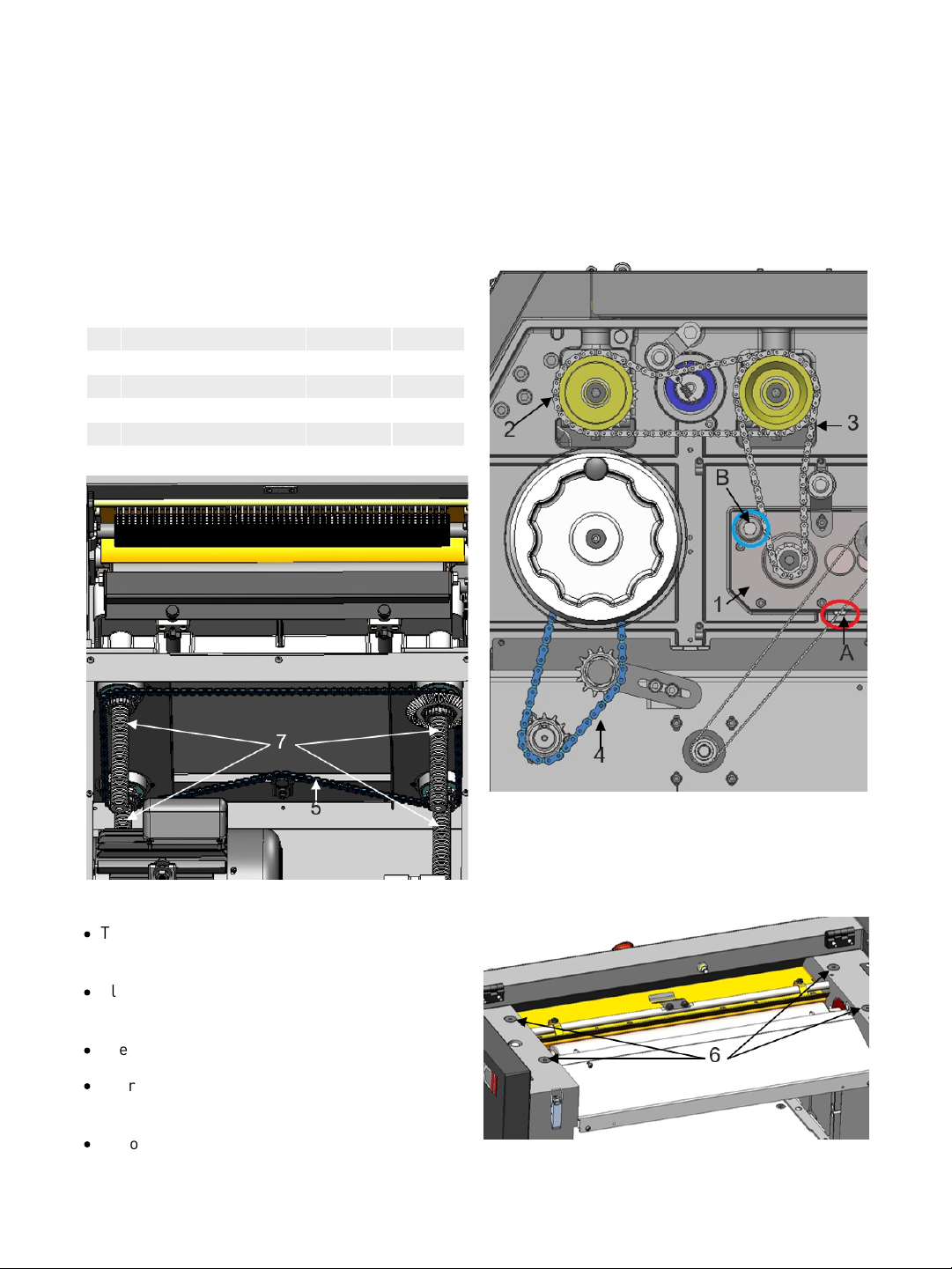
Figure 25 Table
NO.
POSITION
GREASE
OIL1GEAR BOX
NO
YES2CHAIN
YES
NO3CHAIN
YES
NO4CHAIN
YES
NO5CHAIN
YES
NO6BUSHING
NO
YES7LEAD SCREW
YES
NO
FIGURE 26: LUBRICATION
FIGURE 25: LUBRICATION
·
The Gear Box oil must be changed after 2500
hours of work. (Fig. 25)
·
All chains must be lubricated regularly. (Fig. 25
& 26)
·
Every 30 hours, lubricate the bushings. (Fig. 27)
·
Lubricate the four lead screws regularly. (Fig.
26).
·
Teflon Lube is the preferred lubrication for the
lead screws.
FIGURE 27: LUBRICATION
Lubrication
Regular monitoring and replacement of lubrication is needed.
Page 35

Troubleshooting
Symptom
Possible Cause
Possible Solution
Machine will not
start
1. Fuse blown or circuit breaker tripped
2. Cord damaged
3. Not connected to power source
4. Connected to wrong voltage
5. Top cover is open
6. Emergency stop button pressed
7. Overload tripped
1. Replace fuse or reset circuit breaker
2. Have cord replaced
3. Check connection
4. Check voltage
5. Close top cover
6. Rotate emergency stop button
clockwise until it pops out
7. Remove lower rear cover on the base
and press reset switch found inside
Cutterhead does
not come up to
speed
1. Low current
2. Motor not connected to correct voltage
1. Contact local electric company
2. Refer to motor nameplate for correct
voltage
Workpiece stops
when feeding
1. Too much material being removed in
one pass
2. Chipbreaker or pressure bar set too low
3. Insufficient pressure on in- feed or outfeed rollers
1. Reduce the amount of material being
removed
2. Raise the pressure
3. Increase pressure on in-feed or outfeed rollers
Snipe
1. 1. Incorrect setting for infeed, out-feed
rollers, pressure bar
2. Inadequate support of long boards
3. Table roller not set properly
1. Adjust feed system
2. Support long boards with extension
rollers
3. Adjust table roller until desired results
are achieved.
Fuzzy Grain
1. Planing wood with a high moisture
content
2. Dull knives
1. Allow wood to dry properly
2. Rotate or replace knives.
Poor feeding of
lumber
1. Inadequate feed roll pressure
2. Planer bed dirty
3. Drive-belt(s) slipping
4. Dirty feed rollers
5. Incorrect setting for in-feed, out-feed
rollers, pressure bar
1. Adjust feed roll tension or lower feed
rollers
2. Clean pitch and residue off table with a
non-flammable solvent
3. Increase drive-belt tension
4. Clean feed rollers with a nonflammable solvent
5. Adjust feed system
35PXl16 Sheartec:II Planer \ Troubleshooting
Page 36
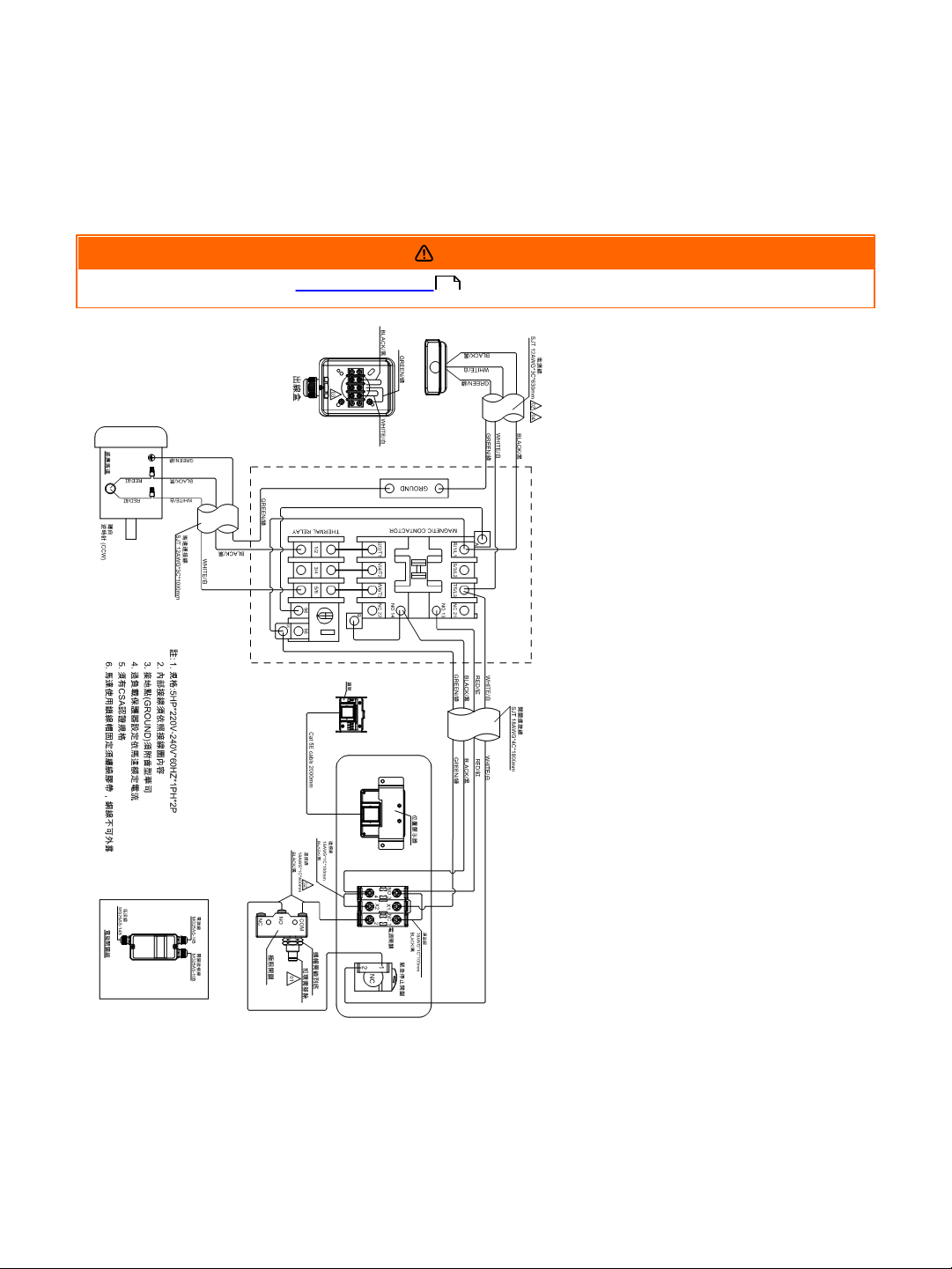
36 PXl16 Sheartec:II Planer \ Wiring
REVIEW ELECTRICAL SAFETY PRIOR TO ANY WIRING PROCEDURES.
Wiring
WARNING
9
Page 37
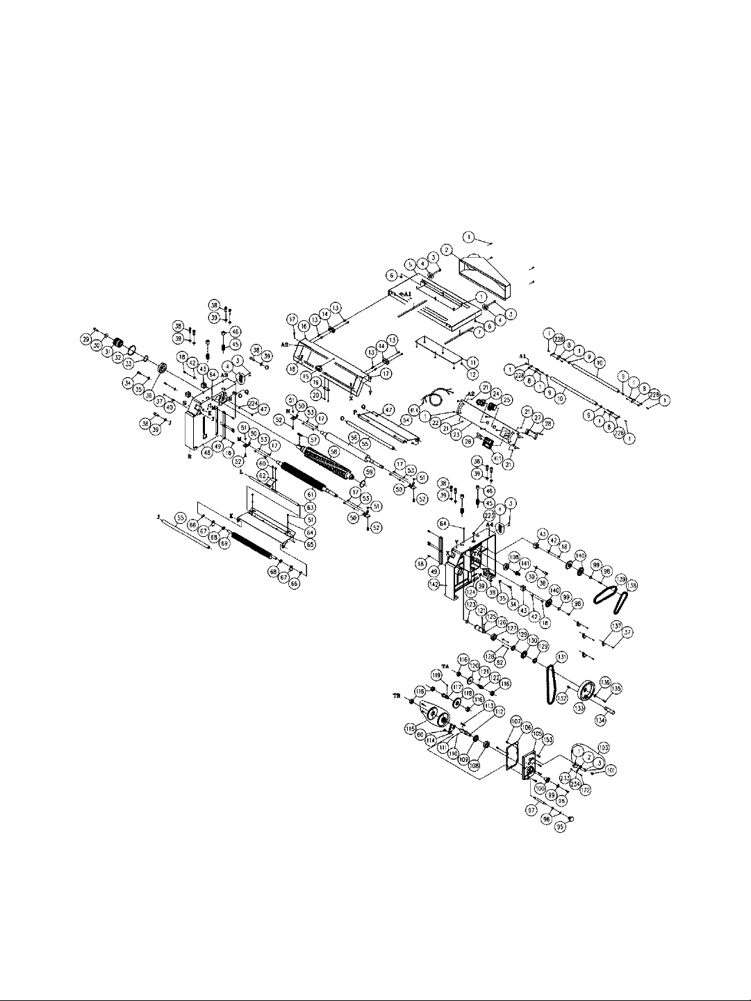
Replacement Parts Diagram
Cutterhead & Drivetrain
37PXl16 Sheartec:II Planer \ Replacement Parts Diagram
Page 38
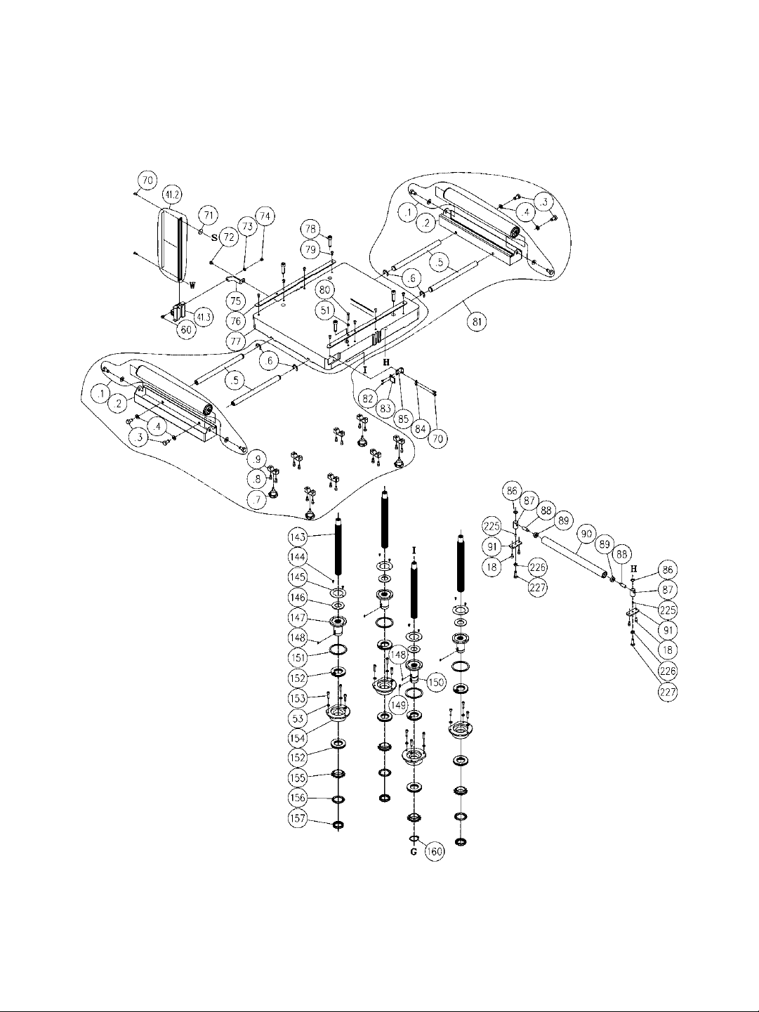
38 PXl16 Sheartec:II Planer \ Replacement Parts Diagram
Table & Lift
Page 39
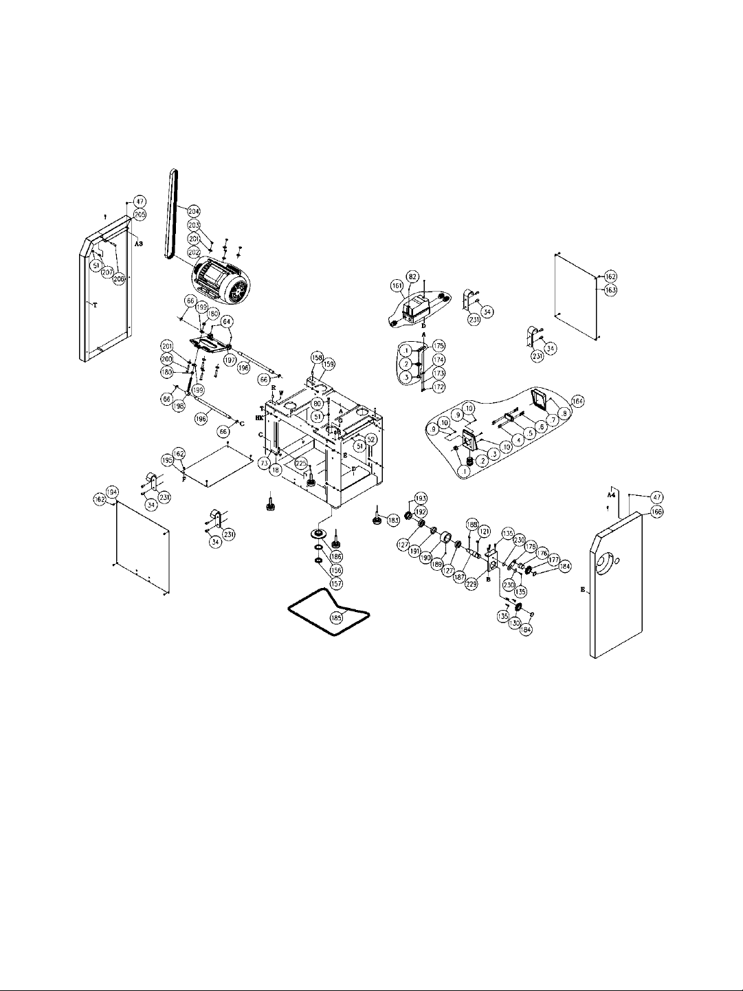
Stand & Motor
39PXl16 Sheartec:II Planer \ Replacement Parts Diagram
Page 40

40 PXl16 Sheartec:II Planer \ Replacement Parts Table
REF NO
PART NUMBER
DESCRIPTION
SPECIFICATION
QTY
1
000804-107
ROUND HEAD HEX SCREW
M5-0.8X12
30
2
174818-000
DUST CHUTE
1
3
000302-201
ROUND HEAD PHILLIPS SCREW
M4-0.7X6
8
4
230409-905
BUCKLE
CT-22
2
5
174817-000
TOP COVER
1
6
340007-615
BLOCK
2
7
200113-615
SPONGE
2
8
174723-904
ROLLER BRACKET
4
9
030119-000
BALL BEARING
605
4
10
361387-906
ROLLER
2
11
251405-620
PC BOARD
1
12
008302-100
HEX LOCK NUT
M5-0.8P/(8BX6H)
6
13
000403-207
FLAT HEAD PHILLIPS SCREW
M6-1.0X16
8
14
679030-008
BUTTERFLY HINGE
2
15
491101-000
LIMITED SWITCH
MJ2-1307
1
16
174816-000
CONTROL BOX COVER
1
17
000002-101
HEX SCREW
M6-1.0X12
10
18
000103-103
CAP SCREW
M6-1.0X12
26
19
174828-000
LIMIT PLATE
1
20
002102-201
FLAT HEAD PHILLIPS LOCK SCREW
M4-0.7X10L
2
21
000301-101
ROUND HEAD PHILLIPS SCREW
M3-0.5X6
4
22
300117-909
SWITCH GUARD
2
24
491153-000
EMERGENCY STOP
NPB22-H01R
1
25
491127-000
POWER SWITCH
M22DP-SF11E230WB(I,O)
1
26
490488-000
BATTERY
AAA
2
27
174750-000
FIXING PLATE
1
28
001202-602
SELF-TAPPING SCREW
M3-1.06X6
2
29
048201-101
HEX LOCK SCREW
M8-1.25X20
1
30
006001-043
FLAT WASHER
8.2-30X4.0
1
31
381423-902
CUTTERHEAD PULLEY
60HZ
1
32
010121-000
RETAINING RING
RTW-80
1
33
010025-000
RETAINING RING
STW-40
1
34
000104-104
CAP SCREW
M8-1.25X16
10
35
006001-054
FLAT WASHER
8.5-20X2.0
2
36
030223-002
BALL BEARING
6208
1
37
000302-102
ROUND HEAD PHILLIPS SCREW
M4-0.7X8
5
38
000105-102
CAP SCREW
M10-1.5X25
12
39
006307-300
SPRING WASHER
10.2-18.5
12
40
021107-100
WIRE FIXING BUCKLE
ACC-1.5-B
1
Replacement Parts Table
Page 41

41PXl16 Sheartec:II Planer \ Replacement Parts Table
REF NO
PART NUMBER
DESCRIPTION
SPECIFICATION
QTY
41
924681-001
DIGITAL READ OUT ASSEMBLY
1
.1
491210-000
DIGITAL READ OUT
WR5502CT
1
.2
950788-001
SENSOR STRIP
WR7003
1
.3
491128-000
SENSOR
WR5501
1
.4
730139-001
CABLE
CAT 5E/RJ45-8P8CT-A/2M
1
42
006001-034
FLAT WASHER
6.7-16X2.0
4
43
130384-000
BUSHING
4
45
280276-000
SPRING
4
46
380200-901
SCREW
4
47
000801-202
ROUND HEAD HEX SCREW
M6-1.0X12
9
48
051446-000
COLUMN-L
1
49
381405-902
FIXING PLATE
4
50
174825-000
ADJUSTABLE PLATE
4
51
008005-100
HEX NUT
M6-1.0(10BX5H)
10
52
000002-104
HEX SCREW
M6-1.0X20
5
53
006303-100
SPRING WASHER
6.5-10.5
20
54
174815-000
CHIP GUIDE
1
55
361382-902
ROD
2
56
361416-000
OUTFEED ROLLER
1
57
012006-001
KEY
8X8X40
1
58
925087-001
HELICAL CUTTERHEAD ASSY.
1
922841-001
INSERTS
10PCS/BOX
1
59
043343-000
RETAINING RING
NBR/46.3-3.1
1
60
000902-102
HEX SCREW W/WASHER
M6-1.0X12
4
61
924829-001
INFEED ROLLER ASSEMBLY
1
62
270015-901
SPRING PLATE
1
63
361380-902
SUPPORT ROD
1
64
000203-104
SET SCREW
M6-1.0X12
6
65
174824-156
FRONT CHIP GUIDE
1
66
010208-000
RETAINING RING
ETW-12
6
67
174722-905
ANTI-KICK-BACK FINGER
45
68
250060-615
SPACER
46
69
361381-902
ANTI-KICK-BACK SHAFT
1
70
000303-104
ROUND HEAD PHILLIPS SCREW
M5-0.8X12
4
71
006001-127
FLAT WASHER
5.5-22X2.0
1
72
001603-102
ROUND HEAD PHILLIPS SCREW
W/FLAT WASHER
M6-1.0X10/6-13.2X1.0
1
73
006001-032
FLAT WASHER
6.6-13X1.0
9
74
008304-100
HEX LOCK NUT
M6-1.0(10BX7H)
1
75
174827-000
BRACKET
1
76
174826-000
GUIDE PLATE
2
77
051448-000
TABLE
1
Page 42

42 PXl16 Sheartec:II Planer \ Replacement Parts Table
REF NO
PART NUMBER
DESCRIPTION
SPECIFICATION
QTY
78
002604-103
CAP LOCKING SCREW
M10-1.5X40
4
79
000801-102
ROUND HEAD HEX SCREW
M6-1.0X12
8
80
000002-106
HEX SCREW
M6-1.0X30
2
81
924834-001
EXTENSION ROLLER ASSEMBLY
1
.1
660300-000
ROLLER
2
.2
174829-904
ROLLER BRACKET
2
.3
000004-101
HEX SCREW
M10-1.5X20
4
.4
006307-100
SPRING WASHER
10.2-18.5
4
.5
361386-902
EXTENSION ROLLER ROD
4
.6
010202-000
RETAINING RING
ETW-17
4
.7
230131-000
BOLT
4
.8
000103-103
CAP SCREW
M6-1.0X12
16
.9
130395-903
BUSHING
8
82
000302-701
ROUND HEAD PHILLIPS SCREW
M4-0.7X6
6
83
250463-620
POINTER
1
84
006001-009
FLAT WASHER
5.2-10X1.0
2
85
174561-000
POINTER FIXING PLATE
1
86
006704-100
WAVES WASHER
WW-12
2
87
361365-902
GUIDE BLOCK
2
88
361384-902
ROLLER SHAFT
2
89
030005-001
BALL BEARING
608
2
90
190026-000
ROLLER
1
91
174763-904
ADJUSTABLE PLATE
2
95
250372-615
KNOB
1
96
043303-000
RETAINING RING
P12
2
97
360358-901
SHAFT
1
98
000002-203
HEX SCREW
M6-1.0X16
3
99
006001-021
FLAT WASHER
6.2-22X3
3
100
150008-000
CHAIN SPROCKET
1
101
290104-902
SHOULDER SCREW
1
103
924699-001
IDLER ASSEMBLY
1
.1
174685-902
IDLER BRACKET
1
.2
130095-000
IDLER
1
.3
360561-902
IDLER SHAFT
1
105
090358-000
GEARBOX COVER
1
106
340012-615
GEARBOX GASKET
1
107
360355-901
PIN
2
108
030208-002
BALL BEARING
6204
2
109
043505-000
OIL SEAL
SC25X47X6
1
110
280052-000
SPRING
1
111
017002-000
STEEL BALL
Ψ6
1
112
360357-000
SHAFT
1
Page 43

43PXl16 Sheartec:II Planer \ Replacement Parts Table
REF NO
PART NUMBER
DESCRIPTION
SPECIFICATION
QTY
113
012004-003
KEY
6X6X40
1
114
130404-000
SHIFTING CLAW
1
115
924811-001
GEAR ASSEMBLY
1
116
030205-002
BALL BEARING
6201
5
117
320356-000
SHAFT
1
118
320198-000
GEAR
1
119
012003-002
KEY
5X5X10
1
120
320406-000
GEAR
52T
1
121
012003-003
KEY
5X5X12
3
122
320160-000
SHAFT
1
123
043337-000
O-RING
P22
1
124
043401-000
PLUG
PT1/4”-19
1
125
012002-011
KEY
4X4X15
1
126
361383-902
HANDWHEEL ASSEMBLY
1
127
030104-001
BALL BEARING
6005
3
128
006001-003
FLAT WASHER
4.3-12X1.0
2
129
174700-902
SPACER
2
130
380259-000
SPROCKET
2
131
016019-000
CHAIN
#40-42P
1
132
000702-104
FLAT HEAD HEX. SCREW
M6-1.0X16
1
133
240092-000
HAND WHEEL
1
134
230284-000
FOLDING HANDLE
HL-65
1
135
000103-105
CAP SCREW
M6-1.0X15
8
136
006001-026
FLAT WASHER
6.4-20X3.0
1
137
021103-100
WIRE FIXING BUCKLE
ACC-3-B
4
138
016322-000
CHAIN
#06B-42P
1
139
016311-000
CHAIN
#06B-54P
1
140
150029-000
CHAIN SPROCKET
3
141
320405-000
GEAR
1
142
051447-000
COLUMN-R
1
143
361314-902
LIFTING LEAD SCREW
4
144
000805-705
ROUND HEAD HEX SCREW
M4-0.7X8
8
145
175016-902
#N/A
4
146
660289-000
PACKING
4
147
051416-902
LEAD SCREW SEAT
3
148
012001-003
KEY
3X3X10
4
149
012002-005
KEY
4X4X12
1
150
051415-902
MAIN LEAD SCREW SEAT
1
151
660290-000
PACKING
4
152
920133-001
THRUST BEARING
8
153
000103-107
CAP SCREW
M6-1.0X20
17
154
381404-902
BEARING HOUSING - TOP
4
Page 44

44 PXl16 Sheartec:II Planer \ Replacement Parts Table
REF NO
PART NUMBER
DESCRIPTION
SPECIFICATION
QTY
155
150016-000
LIFTING SPROCKET
4
156
170746-901
TEETH WASHER
4
157
130094-903
LOCK NUT
4
158
360413-901
FIXING PIN
4
159
174822-000
BASE CASTING
1
160
010014-000
RETAINING RING
STW-35
1
161
938011-001
MAGNETIC SWITCH ASSEMBLY
5HP/220V-240V/1PH/CSA
1
162
000801-108
ROUND HEAD HEX SCREW
M6-1.0X8
12
163
174846-000
BASE REAR COVER
1
164
925021-001
POWER CORD ASSEMBLY
1
.1
021803-000
BUCKLE
NB-1925
1
.2
023701-007
RELIEF BUSHING
MG25AS-14B
1
.3
491116-000
TERMINAL BASE
1
.4
250573-615
BUSHING
4
.5
490336-000
TERMINAL BLOCKS
1
.6
000303-110
ROUND HEAD PHILLIPS SCREW
M5-0.8X30
4
.7
490124-000
TERMINAL COVER
1
.8
003303-102
ROUND HEAD PHILLIPS SCREW
3/16”-24X1/4”
1
.9
006502-100
TEETH WASHER
5.3-10(BW-5)
2
.10
000303-104
ROUND HEAD PHILLIPS SCREW
M5-0.8X12
4
166
174820-000
SIDE COVER - R
1
172
000102-104
CAP SCREW
M5-0.8X12
3
173
006302-300
SPRING WASHER
5.1-9.3
2
174
006001-012
FLAT WASHER
5.3-12X1.0
2
175
920135-001
TENSION WHEEL ASSEMBLY
1
.1
170759-902
BRACKET
1
.2
250072-615
CHAIN SPROCKET
1
.3
360247-901
SHAFT
1
176
361431-902
IDLER SHAFT
1
177
150001-000
IDLER
1
178
175052-902
IDLER BRACKET
1
180
008007-100
HEX NUT
M10-1.5P(17BX8H)
2
183
230403-000
FEET
4
184
010011-000
RETAINING RING
STW-25
2
185
016228-000
CHAIN
Z410-120P
1
186
320403-000
BEVEL GEAR
1
187
361312-902
LIFTING SHAFT
1
188
012003-004
KEY
5X5X15
1
189
000204-102
SET SCREW
M8-1.25X10
1
190
381402-902
BEARING HOUSING
1
191
381403-902
SPACER
1
192
320207-000
BEVEL GEAR
1
Page 45

45PXl16 Sheartec:II Planer \ Replacement Parts Table
REF NO
PART NUMBER
DESCRIPTION
SPECIFICATION
QTY
193
000202-102
SET SCREW
M5-0.8X8
1
194
174819-000
BASE FRONT COVER
1
195
174821-000
BASE TOP COVER
1
196
361385-902
SUPPORT ROD
2
197
050287-008
MOTOR PLATE
1
198
380148-000
ADJUSTABLE ROD
1
199
006003-091
FLAT WASHER
13-28X3.0
2
200
000003-108
HEX SCREW
M8-1.25X40
4
201
006001-041
FLAT WASHER
8.2-22X3.0
8
202
901226-001
MOTOR ASSEMBLY
5HP/220-
240V/60HZ/1PH/2P
1
.1
960007-001
MOTOR
5HP/220-
240V/60HZ/1PH/2P
1
.2
381435-902
MOTOR PULLEY
1
.3
006001-043
FLAT WASHER
8.2(+0.2/-0)-30X4.0
1
.4
048201-101
HEX LOCK SCREW
M8-1.25X20
1
.5
023701-007
RELIEF BUSHING
MG25AS-14B
1
203
008006-800
HEX NUT
M8-1.25P(13BX6.5H)
4
204
014371-000
POLY-BELT
560J-12
1
205
174823-000
SIDE COVER - L
1
206
360579-902
SUPPORT PIN
1
207
280089-901
SPRING
1
208
471037-084
CONNECT CORD
18AWG/1C/100
1
209
471037-085
CONNECT CORD
18AWG/1C/100
1
210
471037-091
CONNECT CORD
18AWG/1C/400
1
211
471037-111
CONNECT CORD
18AWG/1C/400
1
212
230297-615
CORD FIXED CHAIN
4
213
040003-000
HEX WRENCH
3-63MM
1
223
043406-000
PLUG
PT1/4”-19
1
224
006003-114
FLAT WASHER
6.4-16X1.6
1
225
001902-101
SET LOCK SCREW
M6-1.0X10
4
226
008006-100
HEX NUT
M8-1.25P(13BX6.5H)
2
227
000003-105
HEX SCREW
M8-1.25X25
2
228
175019-000
PACKING
4
229
310575-909
BEVEL GEAR BASE
1
230
006001-207
FLAT WASHER
6.3-25X2.0
2
231
174568-156
HOOK
4
233
008004-100
HEX NUT
M5-0.8P(8BX4H)
1
234
280050-000
SPRING
1
Page 46

46 PXl16 Sheartec:II Planer \ Warranty
REGISTRATION
TO PREVENT VOIDING THIS WARRANTY, ALL PRODUCTS
SOLD MUST BE REGISTERED WITHIN THIRTY (30) DAYS OF
RECEIVING. REGISTERING THE PRODUCT WILL ENABLE
THE ORIGINAL PURCHASER TO RECEIVE NOTIFICATIONS
ABOUT IMPORTANT PRODUCT CHANGES AND RECEIVE
CUSTOMER SUPPORT.
HTTPS://LAGUNATOOLS.COM/POLICIES/WARRANTY/
WHAT IS COVERED?
ANY PART, DETERMINED BY LAGUNA TOOLS®, TO HAVE
A DEFECT WILL BE REPAIRED OR REPLACED (AND
SHIPPED), WITHOUT CHARGE. IT IS REQUIRED THAT THE
DEFECTIVE ITEM/PART BE RETURNED TO LAGUNA
TOOLS® WITH THE COMPLAINT AND PROOF OF
PURCHASE IN THE ORIGINAL PACKAGING THAT IT WAS
RECEIVED. IN THE EVENT THE ITEM/PART IS
DETERMINED TO BE VOID OF THIS WARRANTY, THE
CUSTOMER WILL BE RESPONSIBLE FOR THE COST TO
REPLACE THE ITEM/PART AND ALL RELATED SHIPPING
CHARGES.
WHO IS COVERED?
THE APPLICABLE WARRANTY COVERS ONLY THE INITIAL
PURCHASER OF THE PRODUCT FROM THE RECEIPT
DATE. THE ORIGINAL PURCHASER MUST PRESENT THE
ORIGINAL RECEIPT AS PROOF OF PURCHASE.
SHIPPING DAMAGE
LAGUNA TOOLS® AND THE PURCHASING CUSTOMER IS
NOT RESPONSIBLE FOR DAMAGE OR LOSS CAUSED BY A
FREIGHT COMPANY OR OTHER CIRCUMSTANCES NOT IN
THE DIRECT CONTROL OF LAGUNA TOOLS®. ALL
SHIPPING RELATED CLAIMS FOR LOSS OR DAMAGED
GOODS MUST BE MADE TO LAGUNA TOOLS WITHIN
TWENTY-FOUR HOURS OF DELIVERY.
WARRANTY LIMITATIONS
THIS LIMITED WARRANTY DOES NOT APPLY TO NATURAL
DISASTERS, ACTS OF TERRORISM, NORMAL WEAR AND
TEAR, PRODUCT FAILURE DUE TO LACK OF
MAINTENANCE OR CLEANING, DAMAGE CAUSED BY
ACCIDENT, NEGLECT, OR LACK-OF/INADEQUATE DUST
COLLECTION. THE WARRANTY MAY BE VOIDED AGAINST
PROOF OF MISUSE/ABUSE, DAMAGE CAUSED WHERE
REPAIR OR ALTERATIONS HAVE BEEN MADE OR
ATTEMPTED BY OTHERS, USING THE PRODUCT FOR
PURPOSES OTHER THAN THOSE DESCRIBED AS
INTENDED USE (UNLESS WITH CONSENT BY LAGUNA
TOOLS®), MODIFICATION TO THE PRODUCT, OR USE
WITH AN ACCESSORY THAT WAS NOT DESIGNED FOR THE
PRODUCT. IT IS THE RESPONSIBILITY OF THE USER TO
UNDERSTAND BASIC WOODWORKING MACHINERY
SETTINGS AND PROCEDURES AND TO PROPERLY
MAINTAIN THE EQUIPMENT IN ACCORDANCE WITH THE
STANDARDS PROVIDED IN THIS MANUAL.
LENGTH OF WARRANTY
ASIDE FROM BEING FREE OF DEFECTS UPON RECEIVING,
CONSUMABLE PARTS, LIKE CUTTERS AND ABRASIVES,
ARE NOT COVERED BY THIS WARRANTY UNLESS
OTHERWISE STATED BY LAGUNA TOOLS®. THESE PARTS
ARE DESIGNED TO BE USED AT THE EXPENSE OF THE
OPERATOR AND ARE AVAILABLE FOR REPLACEMENT OR
INVENTORY PURCHASE.
2 YEAR – NEW PURCHASES THROUGH AUTHORIZED
DEALERS.
1 YEAR – NEW PURCHASES DIRECTLY FROM LAGUNA
TOOLS.
1 YEAR – BLADES AND ACCESSORIES
Warranty
This machine is covered by a warranty and the purchasing dealer can answer any questions you may have.
Additionally, you can contact Laguna: +1 (949) 474-1200 [email protected].
Every product sold is warranted to be free of manufacturers’ defective workmanship, parts, and materials.
For any questions about this product, the intended use or what it was designed for, customer service, or
replacement parts – please reach out to our customer service department.
Page 47

47PXl16 Sheartec:II Planer \ Warranty
Page 48

LAGUNA AMERICAN HEADQUARTERS
Texas: 744 Refuge Way Suite 200, Grand Prairie, Texas 75050, U.S.A. Phone: +1-800-332-4094
Huntington Beach: 7291 Heil Ave Huntington Beach, CA 92647, U.S.A. Phone: +1-949-474-1200
South Carolina: 825 Bistline Dr. Ste 101, West Columbia, SC 29172, U.S.A. Phone: +1-800-234-1976
Minnesota: 5250 West 74th St, Edina, MN 55439, U.S.A Phone: +1-949-474-1200
DAKE CORPORATION
724 Robbins Road, Grand Haven, MI 49417, United States +1-800-937-3253
LAGUNA EUROPE
Walker Rd, Bardon Hill, Coalville LE67 1TU, United Kingdom. Phone: +44-1530-516921
© 2021 Laguna Tools
 Loading...