

Page 1

TS / TSS Tablesaw
Manual
LAGUNA TOOLS
2072 Alton Parkway
Irvine, California 92606
Ph: 800.234.1976
www.lagunatools.com
© 2017, Laguna Tools, Inc. LAGUNA® and the LAGUNA Logo® are the registered trademarks of Laguna Tools, Inc. All rights reserved.
Model Number: MTSS000020
Page 2

Page 3

3
Table of contents
Safety Rules
Warranty
Noise emission
Specification sheet
Receiving your machine
Unpacking your machine
Introduction to your machine
Assembly and set up
Where to locate your machine
Operating your machine
Maintenance
Troubleshooting
Accessories
Electrical drawing
Spare parts
Exploded view drawings and parts lists
Page 4

4
Safety Rules
As with all machinery there are certain hazards involved with the operation
and use. Using it with caution will considerably lessen the possibility of
personal injury. However, if normal safety precautions are overlooked or
ignored, personal injury to the operator may result. If you have any
questions relative to the installation and operation, do not use the equipment
until you have contacted your supplying distributor.
Read carefully before operating the machine.
1. Keep the working area clean and be sure adequate lighting is
available.
2. Do not wear loose clothing, gloves, bracelets, necklaces or
ornaments. Wear face, eye, respiratory and body protection devices as
indicated for the operation or environment.
3. Be sure that the power is disconnected from the machine before tools
are serviced or an attachment is to be fitted or removed.
4. Never leave the machine with the power on.
5. Do not use dull, gummy or cracked cutting tools.
6. Be sure that the keys and adjusting wrenches have been removed and
all the nuts and bolts are secured.
Page 5

Limited Warranty
New machines and accessories sold by Laguna Tools carry a one-year warranty
effective from the date of shipping. Machines sold through dealers must be registered
with Laguna Tools within 30 days of purchase to be covered by this warranty. Laguna
Tools guarantees all new machines and accessories sold to be free of manufacturers’
defective workmanship, parts and materials. We will repair or replace, without charge,
any parts determined by Laguna Tools, Inc. to be a manufacturer’s defect. We require
that the defective item/part be returned to Laguna Tools with the complaint. Any
machines returned to Laguna Tools must be returned with packaging in the same
manner in which it was received. If a part or blade is being returned it must have
adequate packaging to ensure no damage is received during shipping. In the event the
item/part is determined to be damaged due to lack of maintenance, cleaning or
misuse/abuse, the customer will be responsible for the cost to replace the item/part,
plus all related shipping charges. This limited warranty does not apply to natural
disasters, acts of terrorism, normal wear and tear, product failure due to lack of
maintenance or cleaning, damage caused by accident, neglect, lack of or inadequate
dust collection, misuse/abuse or damage caused where repair or alterations have been
made or attempted by others.
Laguna Tools, Inc. is not responsible for additional tools or modifications sold or
performed (other than from/by Laguna Tools, Inc.) on any Laguna Tools, Inc.
machine. Warranty maybe voided upon the addition of such described tools and/or
modifications, determined on a case-by-case basis.
Software purchased through Laguna Tools Inc. is not covered under this warranty
and all technical support must be managed through the software provider. Software is
non-refundable.
Normal user alignment, adjustment, tuning and machine settings are not covered by
this warranty. It is the responsibility of the user to understand basic machinery
operation, settings and procedures and to properly maintain the equipment in
accordance with the standards provided by the manufacturer.
Parts, under warranty, are shipped at Laguna Tools, Inc.’s cost either by common
carrier, FEDEX ground service or a similar method. Technical support to install
replacement parts is primarily provided by phone, fax, e-mail or Laguna Tools
Customer Support Website. The labor required to install replacement parts is the
responsibility of the user.
Laguna Tools is not responsible for damage or loss caused by a freight company or
other circumstances not in our control. All claims for loss or damaged goods must be
notified to Laguna Tools within twenty-four hours of delivery. Please contact our
Customer Service Department for more information.
Only new machines sold to the original owner are covered by this warranty.
For warranty repair information, call 1-800-332-4094.
Page 6

6
Noise emission
Specification
Blade
12”max x 5/8” bore
Max cut height 12” blade
3 ¾” [2 ½” at 45 deg]
Max cut height 10” blade
2 ¾” [2” at 45 deg]
Dado capacity
13/16”
Main motor
3,5 hp single phase 220 volts 3450 rpm
Breaker
20 amp
Electrical cable [not supplied]
Up to 20’ 10-3 20’ to 50’ 8-3
Scoring motor [Optional]
1,2 hp single phase 220 volts 3450 rpm
Scoring blade [Optional]
120mm x 5/8” bore
Cast iron [ground] table size
31 ½” x 21 ½”
Miter slot
¾” x 3/8”
Extension table pressed steel with ribs and legs
31 ½” x 35”
Sliding table out rigger table [Optional]
Yes
Cutting width on rip fence
50”
Slider length
4’ 2”
Slider travel
5’ 11”
Weight TS
630 lb
Weight TSS
730 lb
Machine footprint
4’ 10” x 3’ x 2’ 10”H
Machine footprint
4’ 10” x 7’ x 2’ 10”H
Dust port
4”
Large throat plate with leveling screws
Yes
Blade guard
Yes
Notes concerning noise emission
Given that there exists a relationship between noise level and exposure times, it is not
precise enough to determine the need for supplementary precautions. The factors
affecting the true level of exposure to operators are clearly the amount of time exposed,
the characteristics of working environment other sources of dust and noise etc. For
example, adjacent machines in other words the level of ambient noise. It is possible that
exposure level limits will vary from country to country.
Page 7

7
Standard equipment supplied
with TS
Spare blank throat plate insert
Rip fence
Extension table with legs
Blade guard
Tool kit
Options for TS
Miter gauge
Spare blank throat plate insert
Sliding table
Mobility kit
Scoring unit
Standard equipment supplied
with TSS
Spare blank throat plate insert
Extension table with legs
Blade guard
Tool kit
Sliding table
Miter fence with flip stop and clamp
Miter fence 90-degree flip stop.
Options for TSS
Miter gauge
Spare blank throat plate insert
Mobility kit
Scoring unit
Sliding table out rigger table
Flip stop
Clamp
Straight line rip plate
24” fence
24” fence with telescopic extension
5 hp single phase [Leason]
Miter fence 90-degree flip stop.
Page 8

8
TSS floor plan
TS floor plan
Page 9

9
Receiving your machine.
Note. It is probable that a third party will deliver your machine.
Before you unpack your new saw you will need to first inspect the packing, invoice and
shipping documents supplied by the driver. Insure that there is no visible damage to the
packing or the machine. You need to do this prior to the driver leaving. All damage must
be noted on the delivery documents and signed by you and the delivery driver. You must
then contact the seller [Laguna Tools] as soon as practical. If damage if found after
delivery, contact the seller as soon as practical.
Introduction to Table saws
This Table saw is designed to give you years of safe service. Read this owners manual in
its entirety before assembly or use.
Parts of the Table saw.
The table saw does not have many parts. The major parts are discussed in this manual. If
you are not familiar with the table saw take the time to read this section and become
familiar with the machine.
Identification.
There is a plate at the back of the machine listing all the manufacturing data including the
serial number, model, etc.
Page 10

10
Cabinet
The cabinet has a large footprint and is a welded construction manufactured from heavy
gauge steel plate [4mm [0.16”] thick]. The cabinet houses all the parts of the machine and
the heavy construction ensures that the saw is stable. This weight also helps to absorb any
vibration that is produced during cutting.
Table
The table is manufactured from cast iron [cast iron is a live material and will move over
time] and is provided with a leveling system to ensure that your table remains flat during
the life of the machine. This system allows you to stress the table and take out any
warpage that occurs over time. The table is attached to the cabinet and located with dowel
pins that are removable should adjustment be needed between the miter slot and the saw
blade. On the TS the table is split so that should you require you can fit a sliding table at
a later date.
Trunnion
The trunnion assembly is attached and doweled to the cabinet. It is a heavy cast iron
construction. It houses the motor, saw spindle, riving knife, tilt mechanism, and vertical
movement adjustment. This is the heart for your saw.
The advantage of attaching the trunnion to the case rather than the table is that its weight
is supported by the cabinet and will not twist or distort the table.
Electrical system
The electrical system consists of an electrical motor, start switch, stop switch and
contactor. No cable or plug is supplied as the length of the cable and the type of plug will
be dependant on your installation.
Rip fence.
The rip fence is a “T” square design that gives superior rigidity and is adjustable for
parallel to the blade.
Dust collection.
Dust collection port is located at the back of the machine and is 4” diameter. It connects
to the bottom of the trunnion assembly and collects the sawdust as it leaves the blade.
You will need a dust collection system with a minimum of 1000 cubic feet per minuite.
Throat plate.
On the TS the throat plate is solid cast iron with an insert that can be slid in or out for
easy change between inserts. It is adjustable for level to the table.
The TSS has a fixed throat plate that has inserts that clip in and out. It is also adjustable
for level to the table.
Page 11

11
Sliding table.
The sliding table is manufactured from heavy aluminum extrusion. The table is supported
by ball bearings that roll on polished round steel rods. The clearance between the ball
bearings and the polished round steel guide rods is adjustable. The advantage of the
bearing system is that there is only point contact between the balls and the rods, which
virtually eliminate the problem of dirt, building up and the sliding table will remain
accurate for many years. When wear takes place the polished round steel rods can be
rotated and present a new surface to the ball bearing.
Miter gauge [Optional].
The miter gauge has a cast iron body with an aluminum fence. The miter gauge is
adjustable for angle and has dowel holes every 15 degrees for quick accurate setting. The
fence is movable in relation to the body so that you can adjust it to suite the job.
Miter fence TSS.
The miter fence is manufactured from cast iron and heavy-duty gauge aluminum
extrusion. It is supplied with a flip stop and a job clamp. It can be set at any angle and has
an adjustable 90-degree flip stop that is fitted to the side of the sliding table.
Mobility kit [Optional]
The mobility kit is easy to fit and the machine is located directly on the floor when the
mobility kit is not in use.
Scoring unit [optional]
The scoring unit can be purchased with the saw or fitted as an option later. The scoring
unit has a separate motor and is adjustable vertically and horizontally. All machines are
supplied with locating / fixing holes and faces machined to accept a scoring unit.
The machine should never be started with both motors engaged. The main motor
must be started and when at full steed then the scoring motor started. If both motors are
started at the same time excessive load is put on to the contactor and it will burn out.
Page 12

12
Where to locate your machine.
Before you remove your machine from the pallet select the area where you will use your
machine. There are no hard and fast rules for its location but below are a few guidelines.
1/ There should be an area at the front and back of the machine suitable for the length of
wood that you will be cutting.
2/ Adequate lighting. The better the lighting the more accurate and safely you will be able
to work
3/ Solid floor. You should select a solid flat floor, preferably concrete or something
similar.
4/ Close to power source and dust collection.
5/ Allow an area for the storage of blanks and cut jobs.
Unpacking your machine.
To unpack your machine you will need tin snips, knife and a wrench.
1/ Using the tin snips, cut the banding that is securing the packing box [If fitted].
WARNING: EXTREME CAUTION MUST BE USED BECAUSE THE BANDING
WILL SPRING AND COULD CAUSE INJURY.
2/ Dismantle the box or remove the row of screws around the base of the box and lift the
box off the pallet. You will need two people to lift the box off the pallet.
3/Using the knife cut the plastic wrap. The extension table, fence and accessories that
were ordered are in the box.
4/ Remove the base mounting bolts that secure the machine to the base of the box.
5/ It is recommended that the machine be removed from the pallet by lifting it with a
hoist or forklift. Remove the pallet and lower to the floor. [To lift with a hoist, four lifting
hooks are provided that fit into the holes at the bottom of the body.]
The machine can be lifted using a forklift truck, sliding it onto the forks or by using a
"SLING" with a lifting capability of 2000 Kg [4400lb]
If no lifting device is available you can fit the mobility kit [if ordered] build a temporary
ramp and roll the machine off the pallet.
Note The machine is heavy; ensure that you have sufficient people.
Note: If you have any doubt about the described procedure seek professional assistance.
Do not attempt any procedure that you feel is unsafe or that you do not have the physical
capability of achieving.
Page 13

13
Fitting the optional mobility kit [If ordered]
Slide the axel through the lower inside holes on the side of the machine and fit the spacer
[large washer] onto the axel.
Fit the wheel assembly, nut and washer on to the axel.
To activate the moblity kit, insert the handle into the tube and rotate so that the machine
is lifted. When in the up position insert the sliding pin.Repeate on the other side of the
machine.
Fit the cast iron bracket to the front of the machine with the bolts provided into the
tapped holes. Move the machine by inserting the transport bar and lifting.
Page 14

14
Assembly and set up
Lifting hooks and tools
Optional mobility kit
Fence system
Optional straight line rip bracket
Extension table and spare throat plate
Miter fence
What you will receive with the machine.
Page 15

15
Cleaning the machine.
Leveling bolt
Switch box shown with optional scoring
switch
Vertical control handle
Angle control handle
Remove the rust protection grease with WD 40 or similar solvent
It is important that you remove all the grease and re lubricate with a Teflon bases
lubricant as Teflon has less tendency to attract sawdust and cause clogging. You should
also wax the table, as this also protects the cast iron from rust.
Leveling the machine.
The machine is provided with 4 leveling bolts. Move your machine to its final position,
and using a sprit level on the table, adjust the leveling bolts so that the table is level in
both directions. Ensure that the machine does not rock.
The start / stop switches are located on the side of the machine next to the blade vertical
control handle. The knob in the center of the control handle, is a lock that locks the blade
in the vertical position selected.
The handle on the front of the machine, controls the angle of the saw blade. The angle
read out is on the side of the machine by the vertical control knob. When moving the
blade to an angle, the yellow-hinged dust plate MUST be closed. Damage may occur if
the yellow hinge plate is not closed.
Page 16

16
Switch cover shown open
To start your machine, release the red stop button by moving the button to the right. The
Riving knife adjustment
Riving knife adjustment
Locking rod
Fitting blade Arbor spacer
door will be released and the green button will be accessible. Press the green button, and
the machine will start. To stop the machine, press the red button.
The machine should never be started with both motors engaged. The main motor
must be started, and when at full steed, then the scoring motor started. If both motors are
started at the same time, excessive load is put on to the contactor, and it will burn out.
To adjust the riving knife for different diameters of saw blade, loosen the clamp screw,
and slide the knife up or down or laterally to suite the blade selected. Once adjustment is
completed, ensure that the screw is re tightened.
To adjust the riving knife parallel and inline with the blade, four adjusting screws are
provided.
Page 17

17
To fit a blade, disconnect the saw from the power. Move the arbor to the maximum up
Dust cover clips
Locking rod
Loosen
Guard in up position
Guard in down position
position. Rotate the saw arbor so that the hole in the arbor lines up with the hole in the
saw table. Insert the locking rod, and loosen the arbor nut. Remove the large clamping
disc, and fit the blade. When refitting the clamping disc, ensure that the key lines up with
the key way. The nut must be tightened, and the locking rod removed before starting the
machine.
Note. The arbor has a left hand thread.
Note. The arbor is shown with the spacer removed. The spacer is only removed when you
fit a dado cutter. It is left on the arbor when fitting a saw blade.
To release the yellow dust cover, release the clips at both ends. Never move the saw
arbor with the dust cover loose, as it could become damaged.
Fit the saw blade guard, and fit a dust hose if required. The size of dust hose should be 1
½”.
Page 18

18
Leveling screws
TS throat plate Insert
Straight edge
TSS throat plate
The throat plate is made from cast iron, and has a phenolic insert. A spare insert is
provided that you can machine to suite your requirements [Dado, Zero clearance, etc].
There are two types of throat plate, TSS and TS. To adjust the TS throat plate, adjust the
leveling screws so that the throat plate is level with the table. To remove the insert slid
out as shown.
To adjust the TSS throat plate, place a rule [straight edge] across the table so that it
extends across the throat plate. Each clamp screw is provided with jacking screws, and by
Page 19

19
loosening the clamp screw, and adjusting the jacking screws, the plate can be adjusted for
Retaining clip
Insert TSS throat plate
Dust port
level to the table, and for parallel to the table. Ensure that the clamping screws are tight
before you use the saw.
On the TSS, releasing the clips and sliding the insert towards the blade will remove the
insert. Note. The blade will have to be in the down position. To fit a new insert, slide into
the throat plate and you will hear a click as the catches engage.
The machine has a dust port at the back of the machine close to the ground. It takes a 4 “
diameter hose, and needs to be connected to a dust collector with a capacity of 1000
cubic feet per minute minimum [The stronger the dust collector the better].
Page 20

20
Dado cuter
Fitting the dado cutter
Dado cutter
Extension table legs
Extension table
Extension table fixing bolt
To fit the dado cutter, disconnect the machine from the power and remove the arbor nut,
clamping disc, and spacer.
Fit the dado and lock in position with the clamp washer and arbor nut. Ensure that the
lock rod is removed before you start the machine. A blank throat plate is supplied that
you can machine to suit the dado that you are using. Optional additional throat plate
inserts are available.
Fitting the extension table
Fit the legs to the table prior to fitting the table to the saw.
Attach the table to the main table with the fixing bolts provided. DO NOT FULLY
TIGHTEN THE BOLTS.
Page 21

21
Straight edge
Extension table Jack screw
Using a straight edge, adjust the legs so that with the straight edge flat on the main table
Fence tube Side angle
Tube fixing bolts
View from underside of tube and
angle
the part of the extension table that is directly above the legs is level with the table.
Above the table fixing bolts are leveling screws. Adjust the leveling screws so the table is
level with the main table, and fully tighten the fixing bolts.
Note. The table is attached to the side angles, and after you have completed all the
adjustments, you will have to drill through the holes in the angles, and attach the table to
the angles, with the screws and nuts provided. Do not drill the holes at this point in time.
Note. Do not level the table or attach the angles until the machine is in the final position.
Fit the angle iron rails to the side of the main table. Make sure that the angle with the
fence holes is on the side of the machine with the on / off switch. Use the countersunk
screws to attach the angle to the main table.
The angle on the other side of the machine is attached with hex bolts.
Fit the fence tube to the angle with the hex bolts and washers from the under side of the
angle. It is recommended that this be assembled with two people, as the tube has a
tendency to slide off the angle during assembly.
The angles will have to be adjusted vertically and this is covered latter.
Page 22

22
Switch box open
Ground
Electrical connection
Note the machine is not supplied with an electrical plug or cable, as the type of plug and
cable, will be dependant on the installation. A qualified electrician must carry out the
electrical installation.
Fitting the electrical cable. The electrical cable is fitted as shown. The recomented cable
size 10.3 gauge for runs of up to 20’. For longer runs up to 50’use cable 8-3 gauge.
Recommended breaker size is 20 amps.
On the machine you will see a wire that is yellow and green, this is the ground wire, the
other colored wires are power. It does not matter what color combination you use. Green
and yellow is ground; all other wiring is power (there is no neutral). On single phase the
wiring can be interchanged as you wish; it would not affect the rotation of the motor. The
direction of rotation of machines with a single: phase supply is predetermined during
production.
Before starting the machine
1/ Read and understand the instruction manual before operating the saw.
2/ If you are still not thoroughly familiar with the operation of the saw get advice from a
qualified person.
3/ Make sure the machine is properly grounded and that the wiring codes are followed.
4/ Do not operate the machine while under the influence of drugs, alcohol, and medicine
or if tired.
5/ Always wear eye protection, safety glasses or a safety shield, and hearing protection.
6 /Wear dust mask; long term exposure to the fine dust created by the saw is not healthy.
7/ Remove your tie, rings, watch, and all jewelry. Roll up your sleeves, and never ware
loose clothing. You do not want anything to get caught in the saw.
8/ Make sure that the guards are in place and use them at all times. The guards protect
you from coming in contact with the blade.
9/ Make sure that the saw blade teeth point in the correct direction.
10/ Stop the machine before removing the scrap piece from the table.
11/ Always keep your hands and fingers away from the blade.
12/ Make sure that you use the proper size and type of blade.
Page 23

23
13/ Hold the work piece firmly against the table. Do not attempt to saw stock that does
Stop switch
Optional Scoring switch
not have a flat surface facing down.
14/ Use a push stick at the end of a cut. This is the most dangerous time, because the cut
is complete and the blade is exposed. Push sticks are commercially available.
15/ Hold the wood firmly, and feed it into the blade at a moderate speed.
16/ Turn off the machine if you have to back the material out of an uncompleted or
jammed cut.
Machine test
Now is the time to test the machine.
Note. Never start the main saw motor and the scoring motor at the same time. It will
damage the magnetic contactor. Always start the main motor and when running at full
speed then start the scoring motor.
1/ Check that the machine is clear of all tools, and other loose objects.
2/ Check that all the adjusting and locking handles are tight.
3/ Check that there is no blade fitted, it is far safer to test the machine with out a blade
fitted.
4/ Start the machine by pressing the green start switch.
5/. Saw arbor is now turning.
6/. Now is the time to check that the safety switch is functioning correctly before you fit a
blade.
7/ With the machine running [no blade fitted] operate the red stop switch by pressing
towards the machine. The motor should have the power removed and slow down.
8/ If the safety switch fails to operate correctly do not use the machine until the fault has
been corrected.
Before you cut any wood read the safety rules at the front of this manual
Page 24

24
To fit the measurement tape.
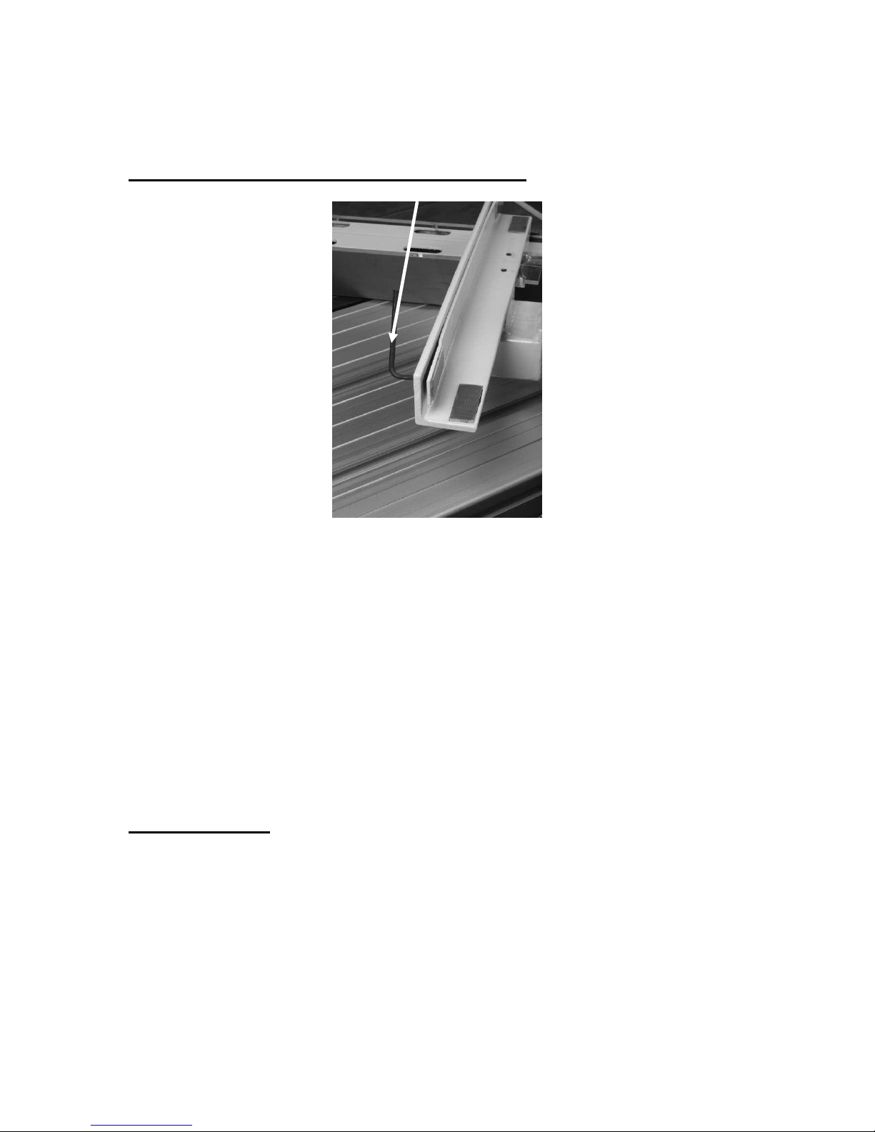
Marking the fence tube
Assembling the measurement tape
Fine adjusting slots
1/ Clean the steel tube with solvent to remove all traces of grease and dirt.
2/ With a blade fitted, and the power disconnected from the machine, fit the fence to the
tube and push it up against the blade so that it is just touching.
3/ Mark a point on the tube with a pencil or pen at the curser line.
4/ Remove the fence. Line the end of the tape up with the pencil mark and peel off the
backing in short sections, sticking the measurement tape to the tube.
Fine adjustment of the hair line can be done in a number of ways but the most effective
way is to lock the fence [1”] and to cut a piece of wood. Measure the wood and adjust the
hairline read out.
Note. Do not over tighten the read out as you may crack the plastic.It is possible to adjust
the read out closer to the tape by inserting washers between the two parts of the readout.
Make sure that the plastic is not in contact with the tape at any point along its travel.
Page 25
25
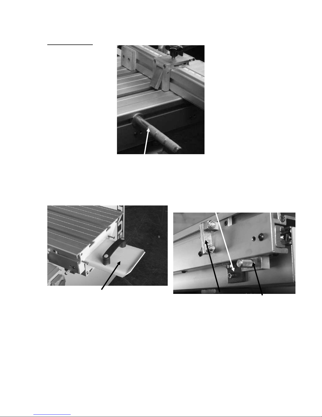
Lublicate the non painted surfaces of the tube with wax or teflon lubricant. This will
Adjusting Wrench
Squaring the fence
ensure that the fence runs smoothly and that the tube is protected from rust.
Adjusting the fence vertically parallel to the saw table.
The angle tube assembly will have to be adjusted vertically to ensure that the gap
between the fence and the table is even along its travel. With the fence close to the blade
place a piece of material 1/16” thick on the table under the fence close to the locking
handle. Loosen the screws that attach the angle to the table, leaving the screw furthest
away from the fence tight. Bring the tube angle assembly up so that it touches the [2]
pads on the underside of the fence, and then tighten the screw close to the fence. Move
the fence to the end of the saw table and repeat. Once the fence is set, tighten all the angle
clamping screws.
Note. It is not critical that the gap under the fence is parallel. It is critical that the rub pad
at the end of the fence is the only part of the fence that touches the table.
Drill through the holes in the steel angle and attach the table to the angle.
You will have to remove the guide tube to drill the holes and then refit it.
Squaring the fence.
A simple way to align the fence is to put a straight edge in the miter slot and align the
fence to the straight edge. If adjustment is required, [2] adjustment screws are provided.
When using the adjustment screws, only move them a small amount at a time. A small
amount of movement on the screw gives a large amount of movement on the fence.
Page 26
26
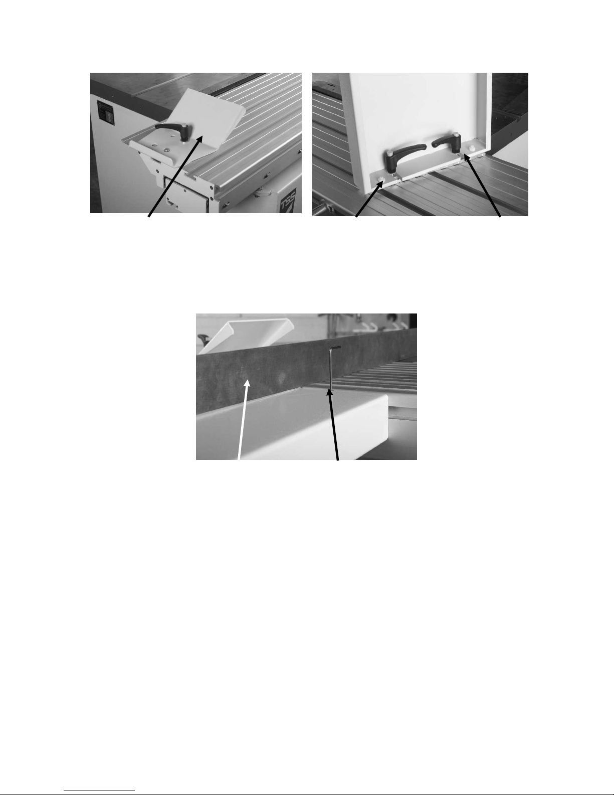
TSS sliding table
Push pull handle
Table end push pull handle
Red transport bracket
Miter fence flip stop Table lock knob
The push pull handle is fitted under the table for shipping and will have to be removed
and re fitted to the side of the table.
To release the table, remove the red transport brackets [One at each end of the table] and
withdraw the table lock knob.
The table will now slide.
Fit the push pull handle with the screws provided, at the end of the table.
Page 27
27
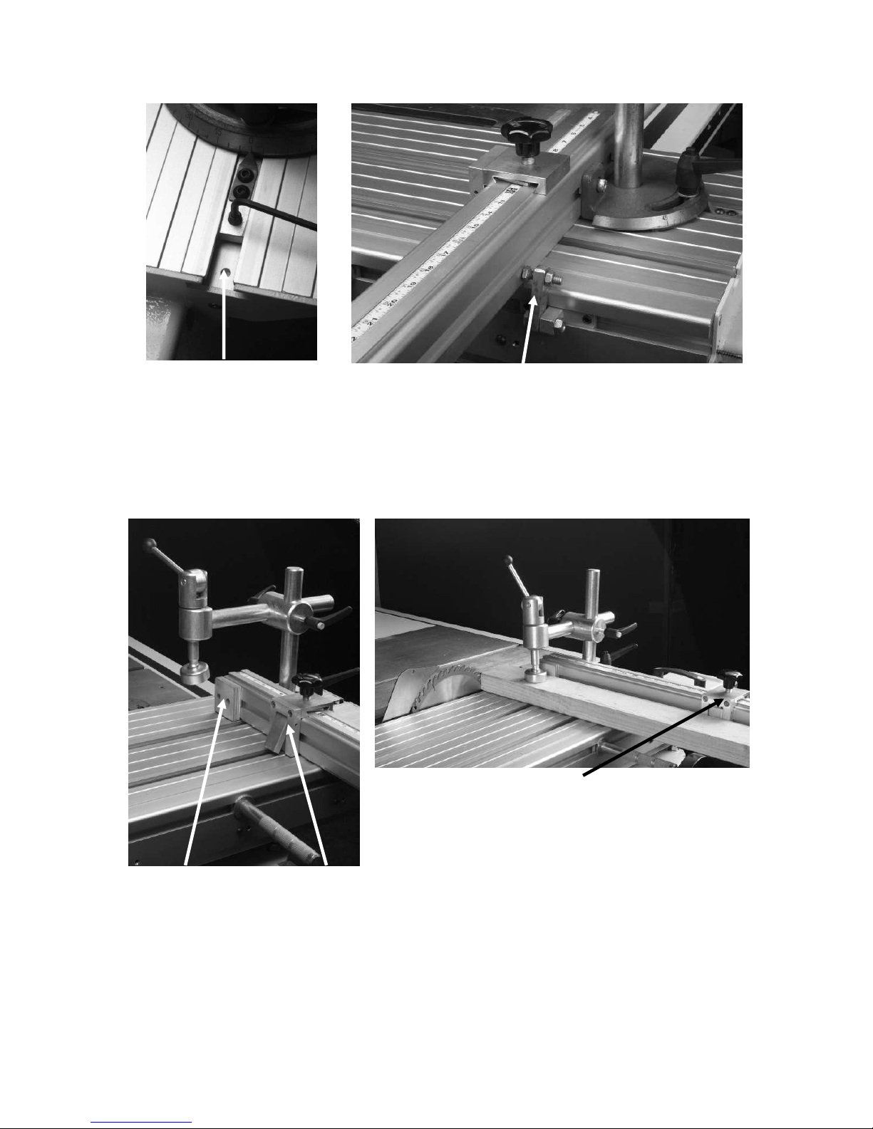
Optional straight line rip stop
Adjusting screws Lock handles
Fit the optional straight-line rip stop at the end of the table as shown.
Straight edge Vertical adjusting screw
The optional side extension table, comes with the clamp bar attached. Loosen the ratchet
handles and slide the bar into the slot on the side of the side of the sliding table. Attach
the table and level as follows
.
To adjust the optional side extension table, lay a straight edge level on the sliding table,
and extended over the side extension table. Loosen the two clamping handles; adjust the
vertical adjustment screws so that the edge of the side extension table is level with the
sliding table. Re-clamp and re-check with the straight edge.
To get the side extension table parallel with the sliding table adjust the two plastic screws
located under the table. Only adjust the screws with the ratchet clamp handles loose.
Page 28
28
Miter fence locking screw
hole
Miter fence flip stop
The miter fence [Cross cut fence] is fitted into the sliding table slot and locating by
Wooden block Flip stop
Flip stop
tightening the lock screw into the hole in the table slot. Fit the clamp shaft through the
casting into the “T” bolt and tighten.
The machine is provided with a fence stop [shown in the up and down position] that is
factory set. Some adjustment may be necessary and can be achieved by loosening the
lock nut, adjusting the bolt, and then re-clamping the lock nut.
Assemble the clamp as shown by screwing the centre post into the “T” bar.
Note. The wood in the view above is resting on the wooden block at the front of the fence
and also on the flip stop.
The miter fence can be fitted to the far end of the table and a short “T” bolt is supplied
that can be used as a reference stop. You will have to move the cast iron miter angle to
the opposite of the fence extrusion.
Page 29
29
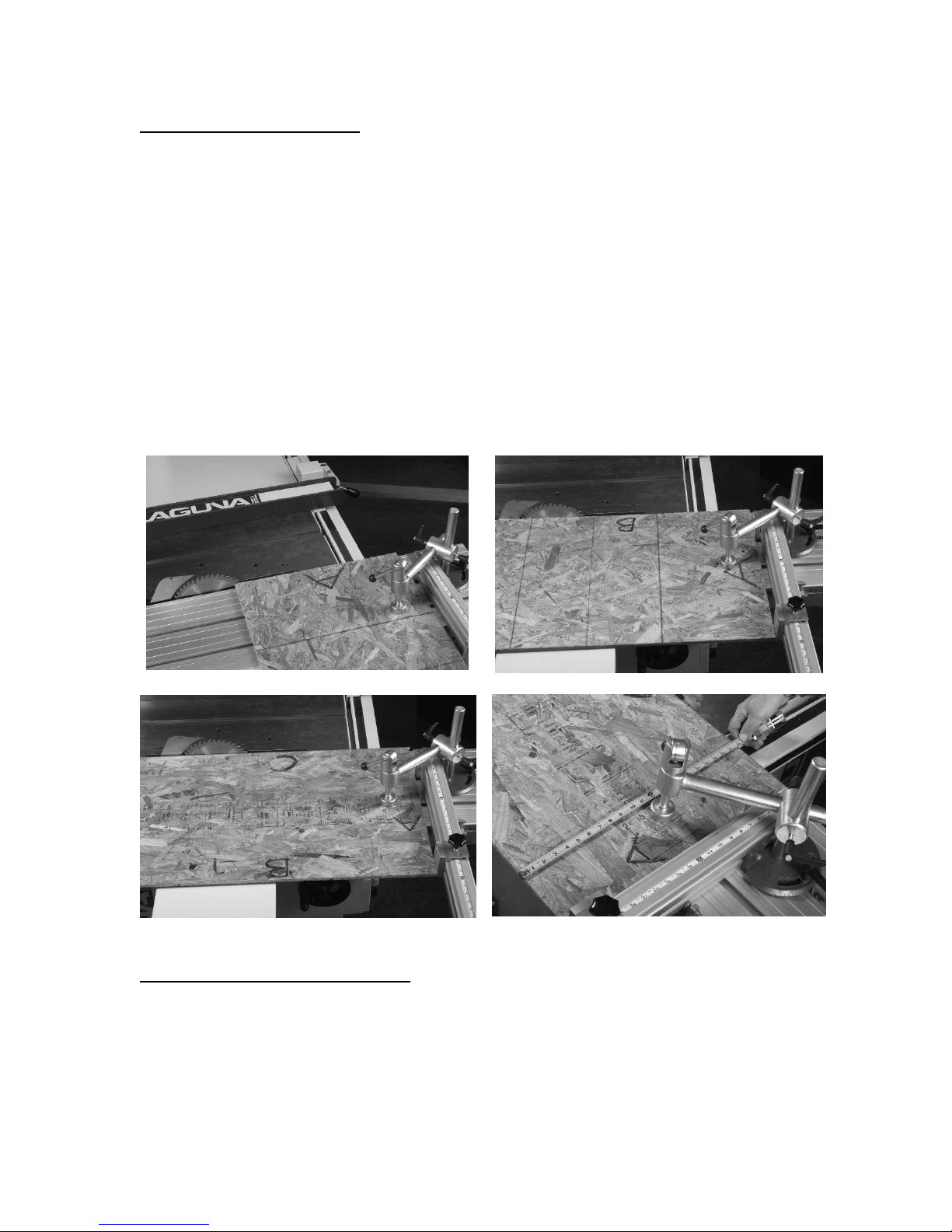
Fine tuning the miter fence.
First cut
Second cut
Third cut
Measure both ends
Several methods are acceptable to fine-tune the fence but we have found that the
following is a very practical way to achieve a square panel.
1/ Clamp the fence locked at 90 degrees against the stop.
2/ Clamp a sheet onto the sliding table and cut a straight edge [edge “A”]. Mark “A”.
3/ Move the sheet so that edge “A” is tight against the fence, clamp in position, cut edge
“B” and mark “B”.
4/ Flip the sheet so that edge “A” is still against the fence but edge “B” is furthest away
from the saw blade, cut edge “C” and mark “C”.
5/ If the sheet is cut square edge B and C should be parallel. Check this by measuring
across the width of the sheet at both ends.
Note. This method will double the amount of error and any adjustment that is required
should be halved. Also the stop is closer to the table than the end of the sheet, so only
adjust the flip stop in very small amounts. Example. You are using a 2’x 2’ sheet and you
are out of parallel by 1/16”, adjust the stop =- 0,01” and repeat the cuts.
Sliding table carriage adjustment.
The sliding table comes factory set, should the table be out of alignment due to shipping
movement, see the maintenance section for adjustment procedure.
Page 30
30
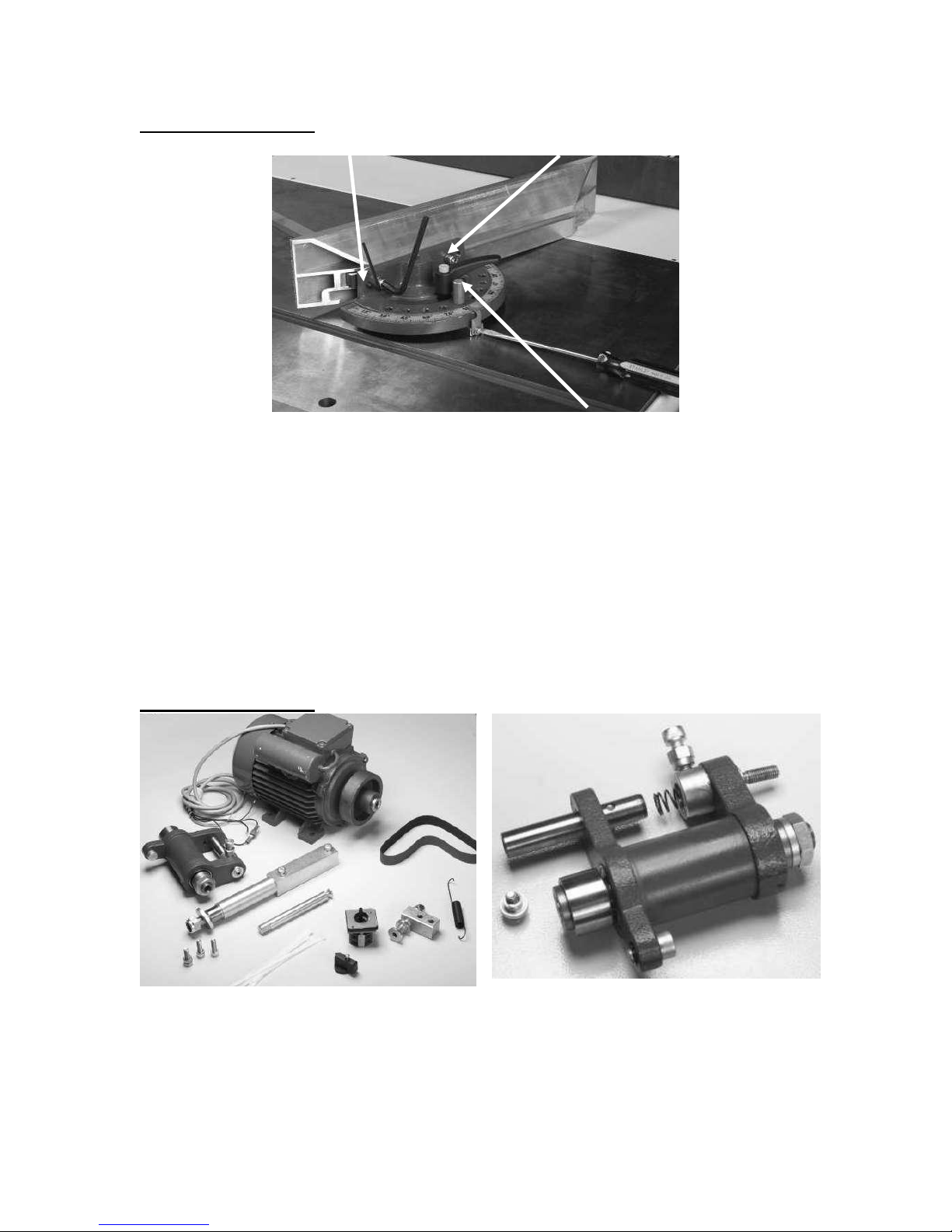
Optional miter gauge.
Jack screw Clamp screw
Optional miter gauge Dowel pin
Parts you will receive
Scoring casting disassembled
The miter gauge has an adjustable pointer; it also has a dowel pin that locks the miter
gauge at 15-degree positions. The fence can be moved to different positions on the miter
gauge to suit the job that you are doing. The fence is cut at 45 degrees at the end to
enable the job to be supported close to the blade when cutting at 45 degrees.
To adjust the pointer, loosen the clamp screw, adjust the pointer and re tighten the clamp
screw.
To move the fence to a different position on the miter gauge, loosen the clamp screws.
Slide the fence to the required position, and re clamp in position.
If you need to move the fence so that the steel clamp block is not supported by the fence,
a jackscrew is provided to hold the steel block parallel.
Optional scoring unit.
The optional scoring can be fitted as follows
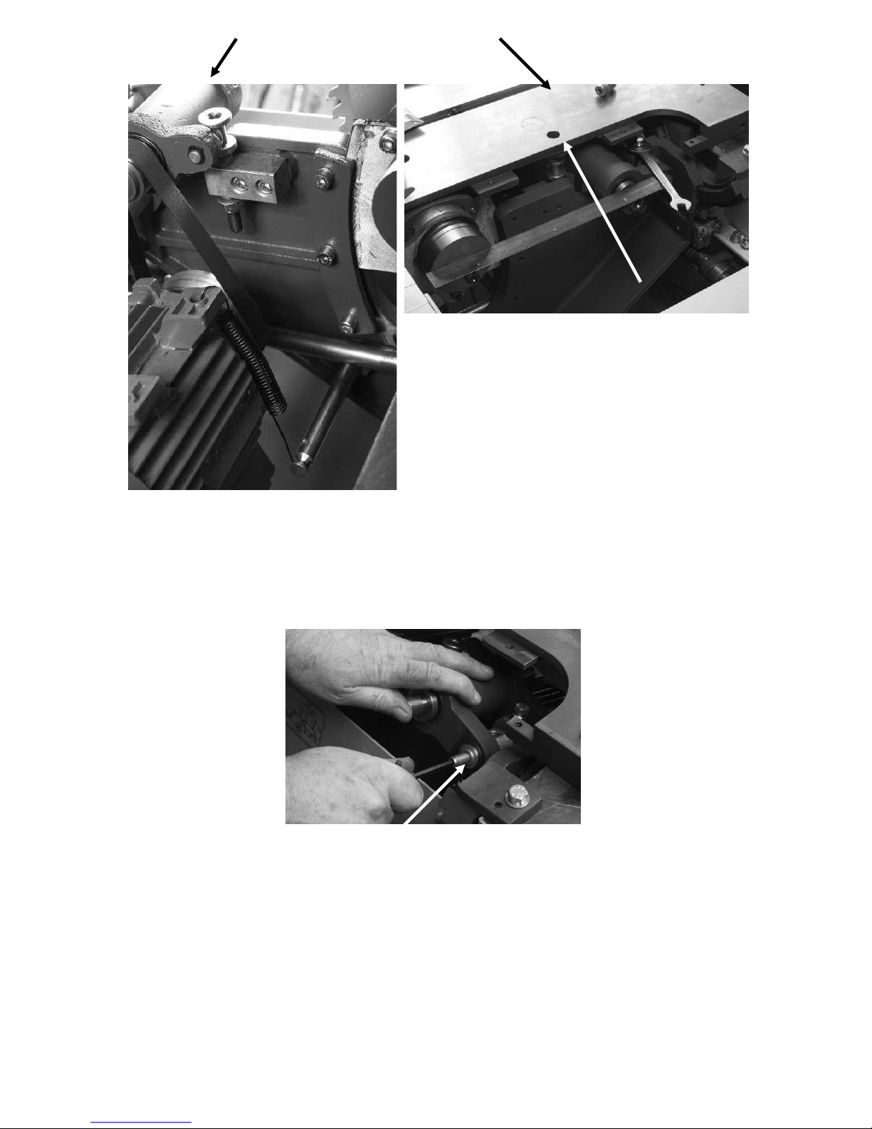
Disassemble the scoring casting as shown.
Page 31
31
Push the shaft through the casting so that the dowel pin lines up with the slot in the bush.
Fitting the adjustment screw
Vertical adjustment screw
Vertical adjustment access hole
Vertical adjustment screw
Lining up the scoring unit
Make sure that the spring is in position.
Assemble the stop bushing, and the screw in the back of the casting.
Assemble the vertical adjustment assembly on the back of the trunnion assembly.
Fit the locking bolt.
Use a straight edge line up the two flanges as shown and tighten the locking bolt.
Fit the double threaded allen set screw as follows.
Push the assembly back as far as it will go and hold in position.
Thread the double threaded set screw in by hand until it contacts the inner thread.
Using an allen key continue to screw the screw in while slowly allowing the pressure of
the screw to push the casting forward.
Once the thread has engaged you can release the casting and continue to tighten the
screw.
Care must be taken during this assembly as you could damage the thread.
Page 32
32
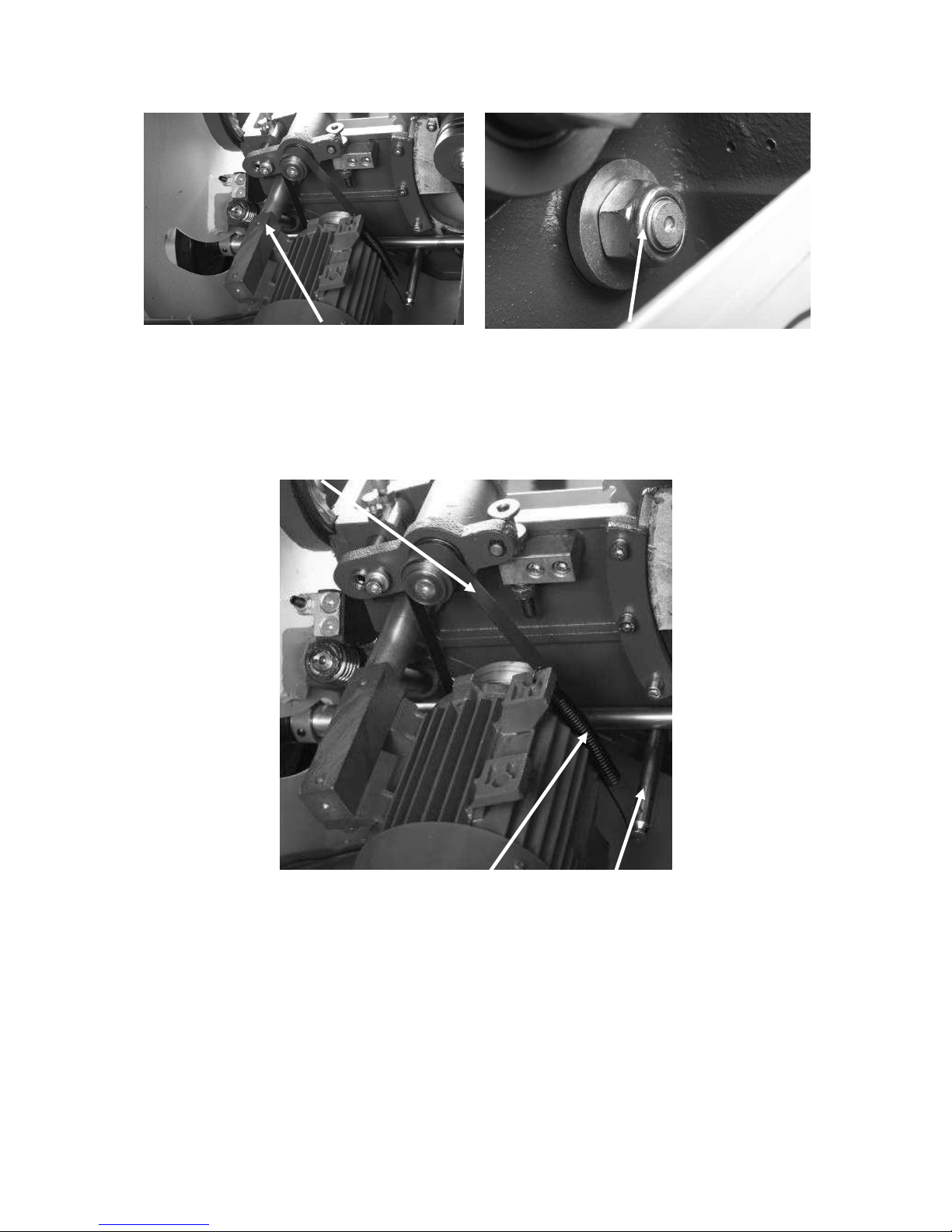
Motor support shaft
Motor shaft nut
Drive belt
Spring
Spring shaft
Assemble the motor to the support shaft.
Push the support shaft through the trunnion and tighten the nut ensuring that the washer is
fitted. DO NOT OVER TIGHTEN THE NUT, AS THE MOTOR MUST BE ABLE
TO MOVE.
Assemble the spring, shaft and drive belt as shown.
Page 33
33
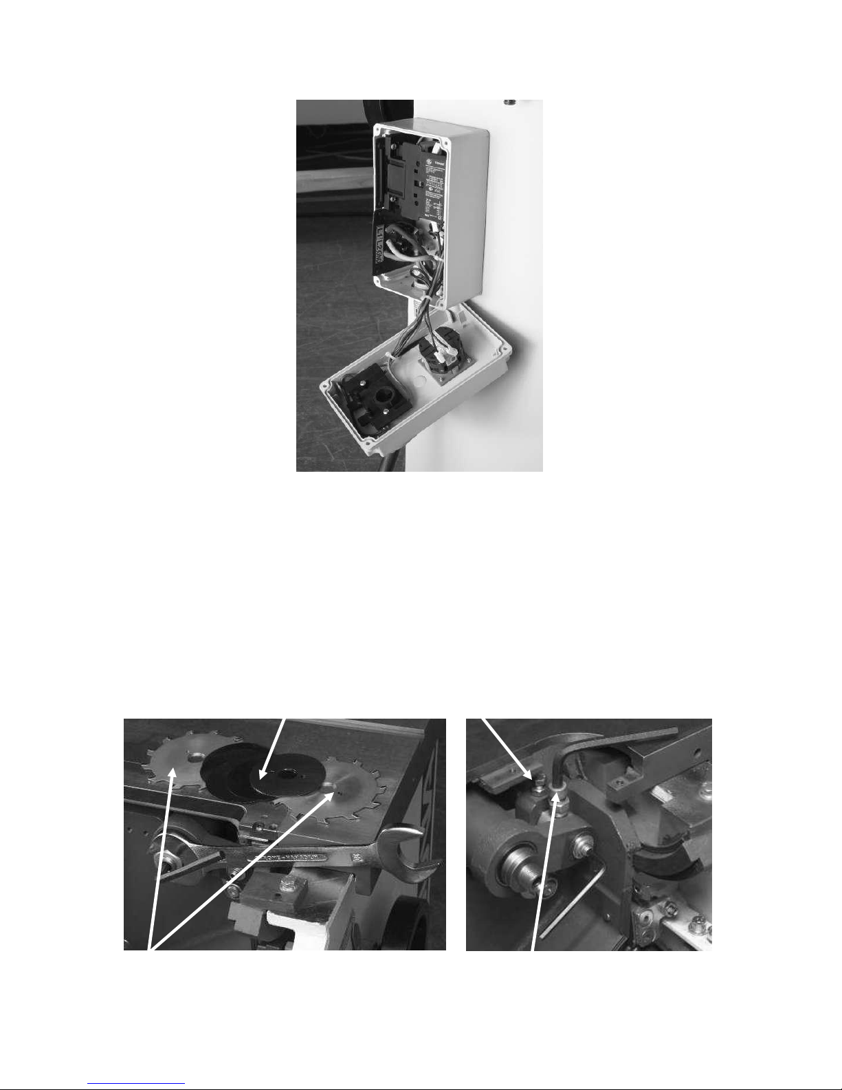
Fitting the scoring switch
With the power disconnected, fit the switch and attach the wiring as detailed in the
Shims
Blades
Clamp screw
Adjusting screw
diagram at the back of the manual.
Note. Never start the machine with both motors engaged at the same time. It will
damage the magnetic contactor.
Note. The electrical box is provided with a cable gland at the back to allow the cables to
enter the electrical box.
Once the cabling has been completed, attach the cables to the cabinet with the cable ties
provided.
Tighten the cable gland to ensure that sawdust will not enter the switch box.
Fitting the scoring blade.
Page 34
34
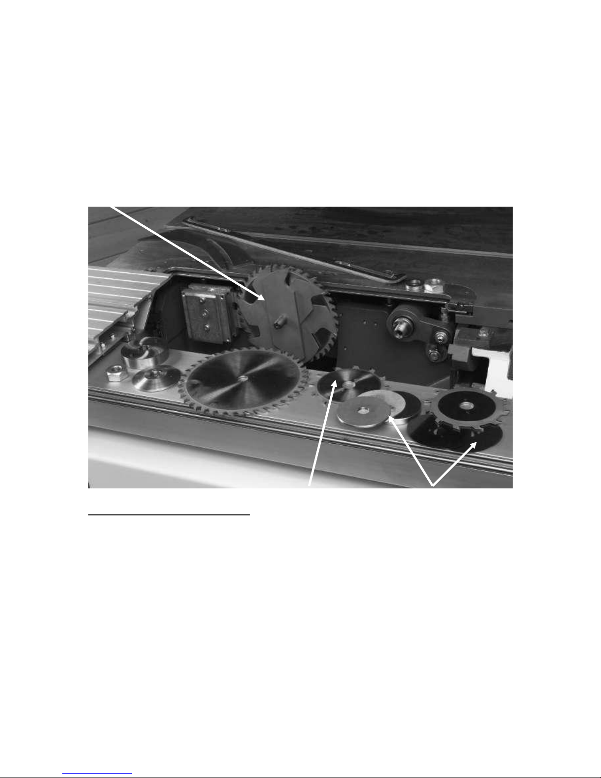
Fit the scoring blade.
Dado cutter
Scoring blades Scoring shims and spacers
Note. Scoring blades are supplied with shims that are used to adjust the width of the
scoring blade, to suite the saw blade that you are using.
Note. The scoring blade rotates in the opposite direction to the main blade.
Adjust the blade so that it is 1/16’ above the saw table. Access to the vertical adjustment
is through the hole in the table [Shown in previous view].
If the scoring blade is cutting too far left or right, loosen the clamp screw and move the
adjustment screw in or out.
Note. The adjustment is very fine.
Fitting Dado scoring [Optional].
If you dado laminates or plywood, it is an advantage to score the surface to prevent
chipping. The scoring unit can be used to do this as follows.
1/ Measure the width of the dado cutter or cut a slot with the dado and measure the slot.
2/ Fit the inside blade of the scoring set onto the shaft, and select shims and spacers to
suit the slot widths [less the width of the two scoring saw blades].
3/ Place the shims, and the outside blade on to the scoring unit shaft, and lock in position
with the nut and washer.
4/ Adjust the height of the scoring cutter so that it is 1/16” above the table.
5/ Make a trial cut on a piece of scrap.
6/ Check that the inside cutter of the scoring unit is cutting inline with the inside cutter of
the dado cutter, and adjust if required.
7/ Check that the outside cutter of the scoring unit is cutting in line with the outside cutter
of the dado and adjust the shims / spacers if required.
Note. The scoring blade rotates in the opposite direction to the main saw blade.
Page 35
35
Maintenance and troubleshooting
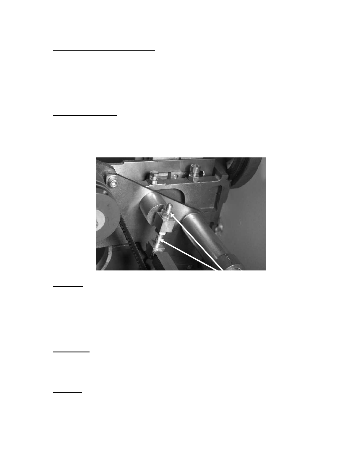
Drive belt tensioning Lock nuts
All tools and machines require regular maintenance, and the table saw is no exception.
This section details the general maintenance and care of your table saw. In general we
recommend that you only use a Teflon based lubricant on the table saw. Regular oil
attracts dust and dirt and the Teflon tends to dry and has fewer tendencies to accumulate
dirt and saw dust on your machine .We also recommend that you wax the table to help
prevent rust.
Weekly maintanince.
1/ Check all nuts and bolts are tight
2/ Clean the machine, and check that the dust hose is clear. Make sure that all moveing
parts are clean and free from saw dust and dirt.
3/ Lubricate all moveing parts with a Teflon based lubricant.
4/ Wax the table and all none painted parts.
Drive belt
The drive belts should last for many years [depending on the usage] but need to be
inspected regularly for cracks, cuts and general wear. If damage is found replace both
belts. Never replace only one belt, and only replace the belts with a matched pair.
To re-tension the belts, loosen both lock nuts. The weight of the motor should put enough
tension on the belts. Then tighten the lock nuts. The belts come factory set but after about
8 hours of use, the belts could need to be re-tensioned, as they will have bedded into the
“V” grooves.
Table insert
The table insert [throat plate] is made of a soft material, and is designed not to damage
the blade should they come in contact. If the blade slot becomes too wide, or the insert
becomes damaged by the blade it should be replaced.
Bearings.
All bearings are sealed for life, and do not require any maintenance. If a bearing becomes
faulty replace it.
Page 36
36
Rust
Limit stop
Scoring unit fitted
Limit stop
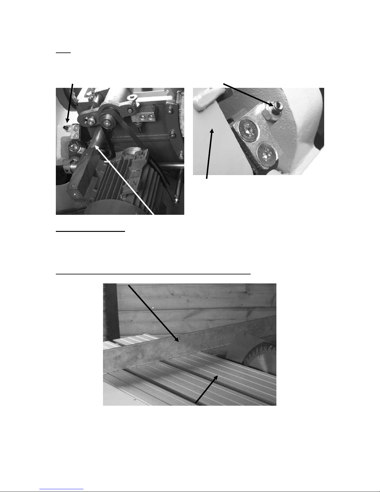
Yellow dust cover
Straight edge
Sliding table
The table saw is made from steel and cast iron. All none painted surfaces will rust if not
protected. It is recommended that the table be coated with wax. All moving none painted
surfaces should be lubricated / protected with a Teflon based lubricant.
Tilt mechanism stops.
The machine is provided with two stops that limit the travel of the tilt mechanism. Both
stops come factory set, but should adjustment become necessary, it can be achieved by
loosening the lock nuts and adjusting the allen set screws.
Sliding table adjustment for vertical level with the main table.
The sliding table comes factory set and should be +_ 0,02” above the main table.
Should the sliding table need to be adjusted use the following procedure.
Page 37
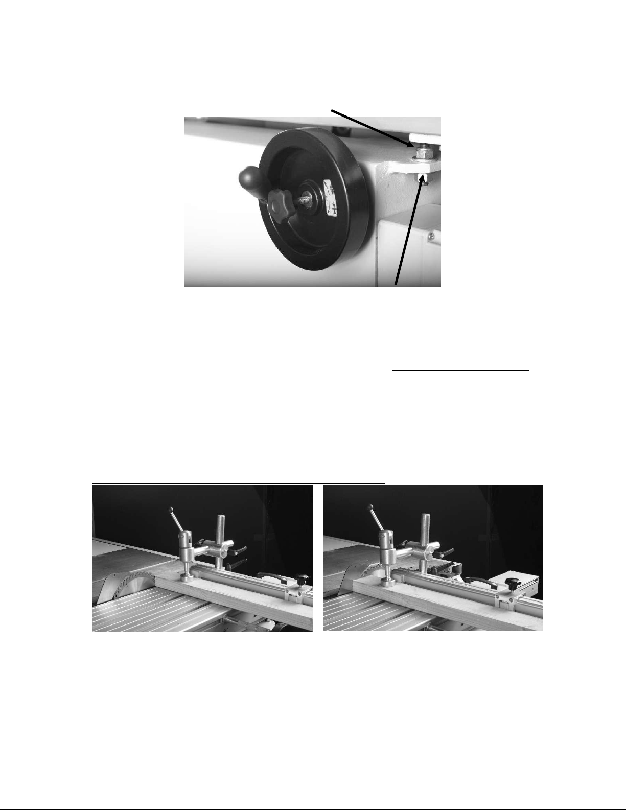
37
Do not attempt this procedure unless excessive movement has taken place during
Top nut
Sliding table adjustment Bottom nut
Wood at front of saw blade
Wood at back of saw blade
shipping.
1/ Lock the sliding table in position with the table lock knob.
2/ Using a straight edge across the sliding table check the gap between the straight edge
and the main table at both ends of the man table.
3/ If adjustment is needed loosen the lower nuts ¼ turn only. Do not loosen the top nuts
4/ Adjust the top nuts so that the gap under the straight edge is parallel and at about
0,02”.
5/ Check that all the top nuts are in contact with the support steel and that there is no
rocking.
6/ Tighten the lower nut and re check. If fine-tuning is required repeat procedure.
Sliding table adjustment for parallel with the saw blade.
The table must run parallel with the saw blade. The gap between the edge of the sliding
table and the table is not important.
To check if the table is running true, clamp a piece of wood [1” x 1” or 2” x 2”] to the
table using the miter fence clamp. Cut the wood slowly. The teeth of the saw blade
should make contact with the front and the back of the blade evenly.
Page 38
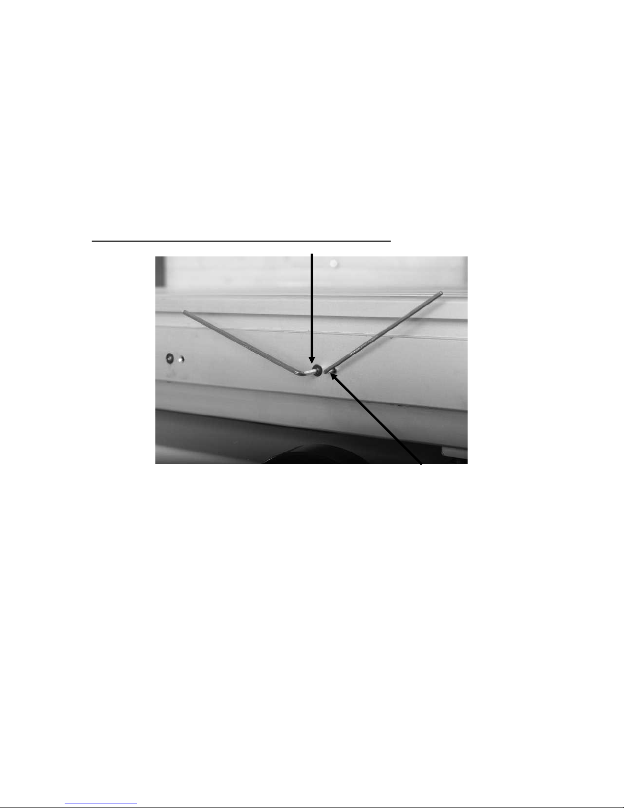
38
A second way to check is to measure the distance between the miter slot and the slot in
Screw “X”
Screw “Y”
the sliding table. The miter slot is parallel with the saw blade and is a good reference
point.
If adjustment is needed proceed as follows.
1/ Loosen three of the lower clamp nuts. Do not adjust the top bolts, as this will affect
the level of the sliding table. Leave one of the bolts that is close to the main table tight.
2/ Swivel the table towards or away from the main table depending on the direction of the
adjustment that is needed. Note only do very small adjustments.
3/ Tighten the three loosened bolts and re check.
4/ If readjustment is necessary repeat the procedure.
Sliding table adjustment for bearing / steel rod clearance.
The sliding table mechanism is designed with 8 ground steel rods, ball bearings run
between the steel rods. The table comes factory set but if there is excessive side
movement adjustment can be made as follows.
1/ Extend the table to one end. The ball carriage will be at the opposite end.
2/ Move the table side to side to check for excessive movement.
3/ Loosen the allen screw [X] and tighten allen screw [Y]. The screws must be adjusted
in pairs, and 2 pairs of screws cover the range of the ball carriage.
Note. The screws should be adjusted in small steps as damage could be caused.
Note. That the [X] screws must be tight before you check for side movement.
4/ Move the table so that the next two pairs of screws are covered by the ball carriage,
and repeat the adjustment procedure.
5/ Continue until all the screws have been adjusted.
Page 39
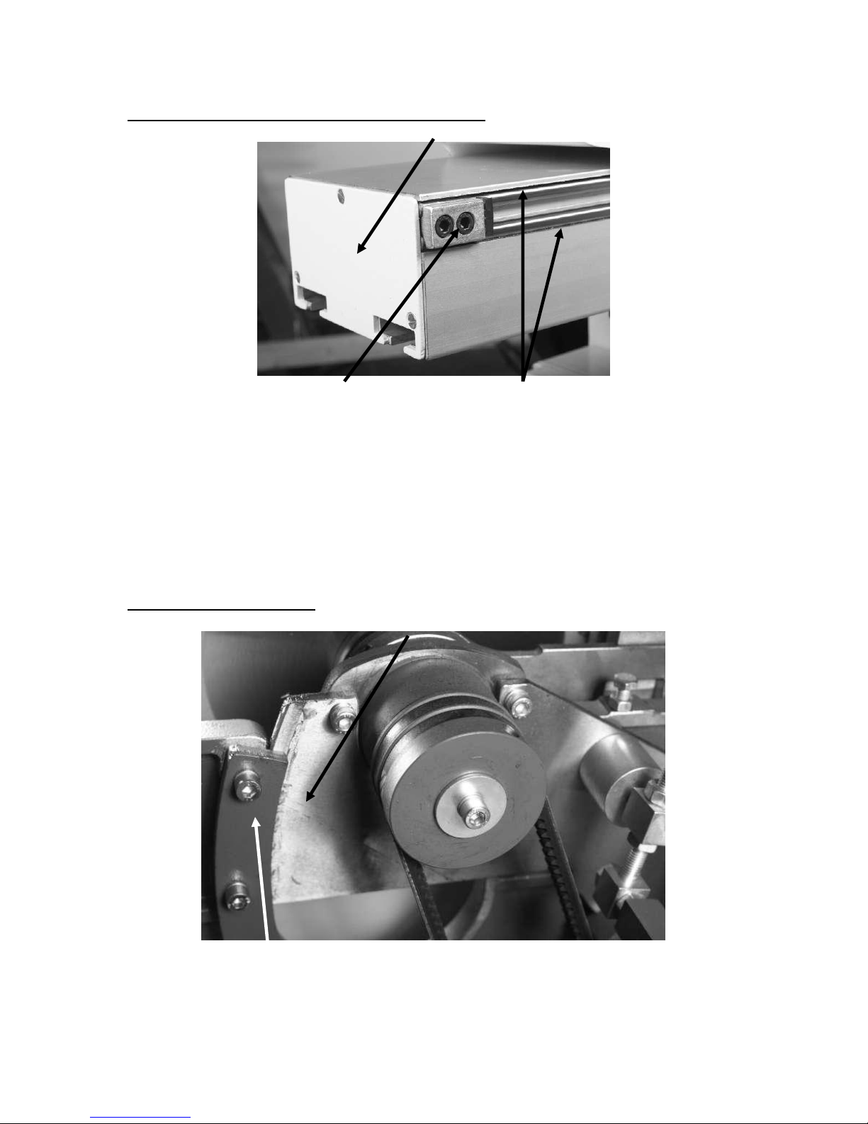
39
Sliding table ground steel rods damaged or warn.
Remove end cover
Clamp screws Steel rods
Guide plate
Bearing plate
If the steel rods become damaged or warn, a new face can be presented to the ball
bearings as follows.
1/ Loosen the clamping screws at each end of the sliding table.
2/ With a brass rod, knock the rod out +_ 1”.
3/ Rotate the rod +_20 degrees.
4/ With the brass rod, knock the rod back level with the end of the table, and retighten the
clamping screws.
5/ Repeat until all the rods have been turned.
Vertical mechanism tight.
1/ Check that nothing is jamming the mechanism
2/ Check that the worm gear and screw are clean and lubricated.
Page 40
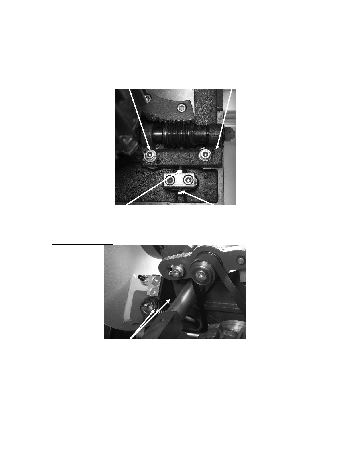
40
3/ Check that the guide plate is not jamming. Clean and re lubricate. Ensue that you clean
Clamp screws Leveling screws
Lock nut Adjusting screw
Tilt worm gear and screw
the whole guide plate by moving the saw arbor to fully up and fully down, cleaning the
exposed part of the guide plate.
4/ Inspect the guide plate and bearing plate for ware and damage. If damaged or warn,
replace.
5/ If the worm gear is warn or excessively tight adjustment is provided.
Note. Contact your supplier before attempting to adjust the worm gear / screw clearance.
You could cause damage or your warrantee could be affected.
Tilt mechanism tight
1/ Check that nothing is jamming the mechanism
2/ Check that the worm gear and screw are clean and lubricated.
3/ If the worm gear is excessively tight or worn, adjustment is provided.
Note. The adjustment mechanism is similar to that shown above for the vertical
mechanism.
Note. Contact your supplier before attempting to adjust the worm gear / screw clearance.
You could cause damage or your warrantee could be affected.
Page 41
41
Miter gauge slot to saw blade adjustment.
Table spring pin
Trunnion spring pin
Table adjustment bolt [Jack]
Trunnion spring pin Trunnion clamp bolt
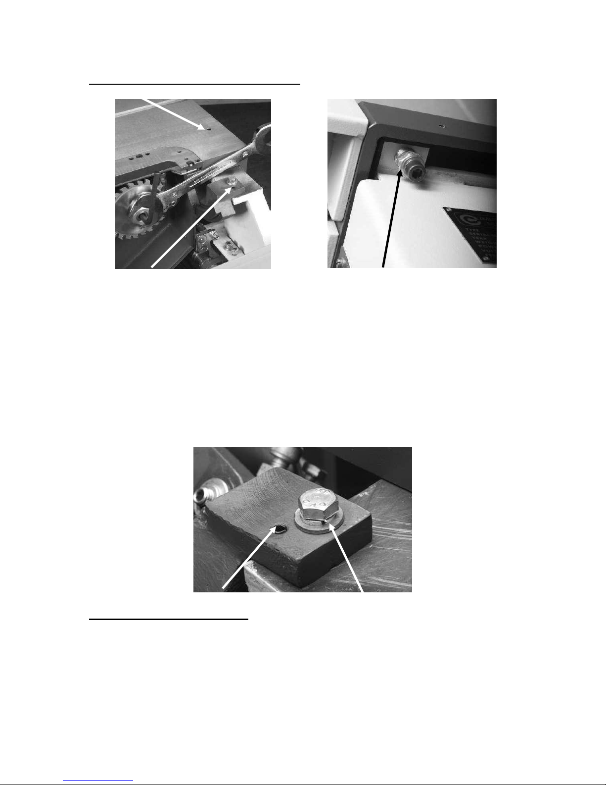
The table and the trunnion assembly are doweled to the body of the saw with 2 [each]
spring pins. The pins stop movement during transport.
The miter slot is factory set to run parallel with the saw blade, but, if movement has taken
place during transportation of your saw, you will have to knock the spring pins through
the table and the body of the saw, and loosen the table to body clamping screws. Adjust
the table to the saw blade and re-clamp the table to the body. Do not refit the spring pins.
Do not remove the spring pins in the trunnion assembly.
It is easer to move the table to the saw blade rather than the trunnion assembly to the
miter slot.
Note. When loosening the table from the body, only loosen the clamp bolts. Do not
change the setting of the table adjustment bolts. You could affect the flatness of the
table.
Adjusting the table for flatness.
The table is made from cast iron, which is a live material and will move over time.
To help keep your table flat, and to compensate for the cast iron movement, the table is
provided with five adjustment points [one at each corner and one in the middle of the
table] The system uses a jack and clamp. The outer bolt [Jack] has a hole through the
middle, which allows the clamp screw to pull the table down directly onto the jack.
If your table flatness has moved you can compensate as follows.
Page 42

42
Table dip in the middle.
Note only adjust the table in very small steps over a period of time. Cast iron is a
very brittle material and will break if over stressed.
1/ Lay an engineer’s straight edge across the table.
2/ Using feeler gauges measure the gap under the straight edge.
3/ Remove the back panel to gain access to the underside of the machine.
4/ Loosen the table clamp bolt in the middle of the table and tighten the table adjustment
bolt [jack]. Only move the bolts a very small amount.
5/ Check the amount that you have moved the table using the straight edge and the feeler
gauges.
6/ Repeat until approximately ¾ of the dip is removed.
7/ Leave for a few days and re-check. The cast iron will continue to move.
8/ Repeat until the dip is removed.
Troubleshooting
Poor cut.
1/ Dull blade. Change the blade.
2/ Bent tooth. Change the blade.
3/ Wrong type of blade for the job.
4/ Scoring not adjusted correctly. [If fitted]
Saw will not start.
1/ Check that the start switch is being depressed fully.
2/ Check that the electrical power cord is plugged into the power outlet.
3/ Check that the electrical supply is on [reset the breaker].
4/ With the power disconnected from the machine, check the wiring in the plug is correct.
Check that the rubber insulation is stripped enough, and is not causing a bad connection.
Check that all the screws are tight.
5/ With the power disconnected from the machine, check the wiring to the machine is
correct. Check that the rubber insulation is stripped enough and is not causing a bad
connection. Check that all the screws are tight
6/ Check that you have the correct power 220V not 110V
7/ Check the ground wire is wired correctly
The machine will not stop.
This is a very rare occurrence as the machine is designed to fail-safe. If it should occur
and you cannot fix the fault, seek professional assistance. The machine must be
disconnected from the power, and never run until the fault has been rectified.
1/ Stop switch faulty. Replace the stop switch.
2/ Internal contactor faulty. Replace the contactor.
Page 43

43
Motor tries to start but will not turn.
1/ With the power disconnected from the machine. Try to turn the blade by hand. If the
blade will not turn check the reason for the jamming. Typical reasons is wood jamming
the blade.
2/ Capacitor faulty. Replace the capacitor.
3/ Motor faulty. Replace the motor.
Motor overheats.
The motor is designed to run very hot, but should it overheat it has an internal terminal
overload protector, that, will shut it down until the motor has cooled down, and then it
will reset automatically. If the motor overheats wait until it has cooled down, and restart.
If the motor keeps shuts down, check for the reason. Typical reasons are dull blade,
overfeeding the wood, motor cooling fan clogged or faulty, motor cooling fins clogged
and excessive ambient temperature.
Squeaking noise.
1/ Check that the motor cooling fan is not contacting the fan cover.
2/ Check the bearings.
3/ Check the drive belt.
Blade slows down during a cut.
1/ Loose drive belt. Re-tension the belt.
2/ Dull blade. Replace the blade or have it re sharpened.
3/ Feeding the wood too fast. Slow down the feed rate.
4/ Insufficient set on the teeth [wood nipping the blade]. Change blade for a blade with
the correct set.
5/ Oil or dirt on the drive belt. Clean or replace the drive belts.
6/ Fence not aligned correctly. Align fence.
Blade overheats.
1/ Dull blade. Change the blade or re sharpen the blade.
2/ Pitch is too small for the depth of cut. Change to a blade with the correct pitch.
4/ Wood too hard for the selected blade. Change the blade.
Machine vibrates.
1/ Machine not level on the floor. Re-level the machine, ensuring that it has no
movement.
2/ Damaged drive belt. Replace both belts.
Poor dust collection.
1/ Check the capacity of the dust collection system. You need a minim of 1000 cubic feet
per minute at the machine. The stronger the dust collection the better.
2/ Check the dust hose is not blocked.
3/ Check that the dust collector is not full.
Page 44

44
Causes of the blade dulling.
1/ Wrong blade for the job.
2/ Over feeding the job.
3/ Cutting painted wood or abrasive material.
Accessories
The following accessories are available from Laguna Tools.
Miter gage.
Mobility kit.
Side extension tables for the TSS.
Flip stops for the TSS miter fence.
Throat plate inserts for TSS and TS.
Saw blades
Scoring blades.
Scoring unit.
Sliding table.
Side flip stops for TSS sliding table.
TSS sliding table clamp.
Work benches.
Page 45
45
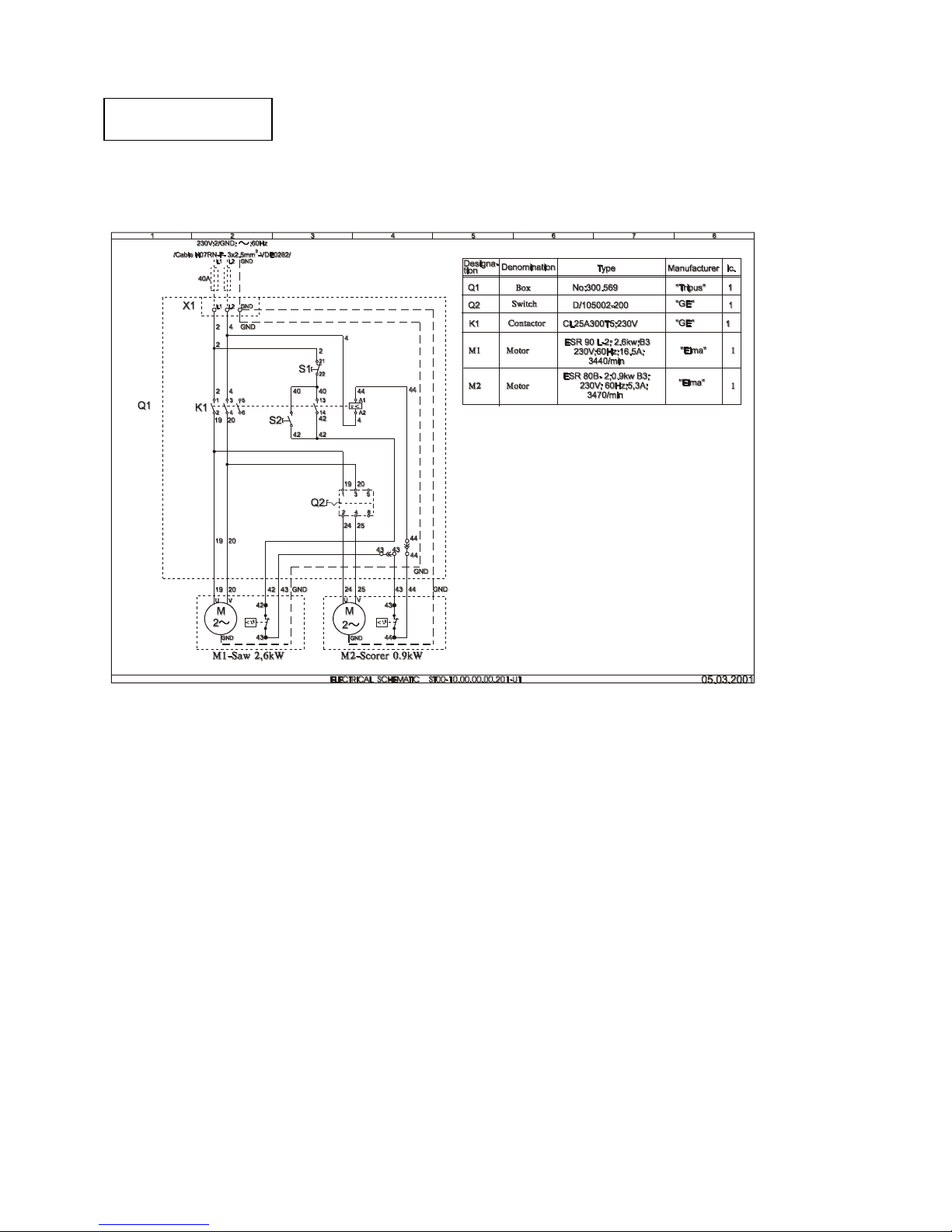
Electrical circuit
Page 46
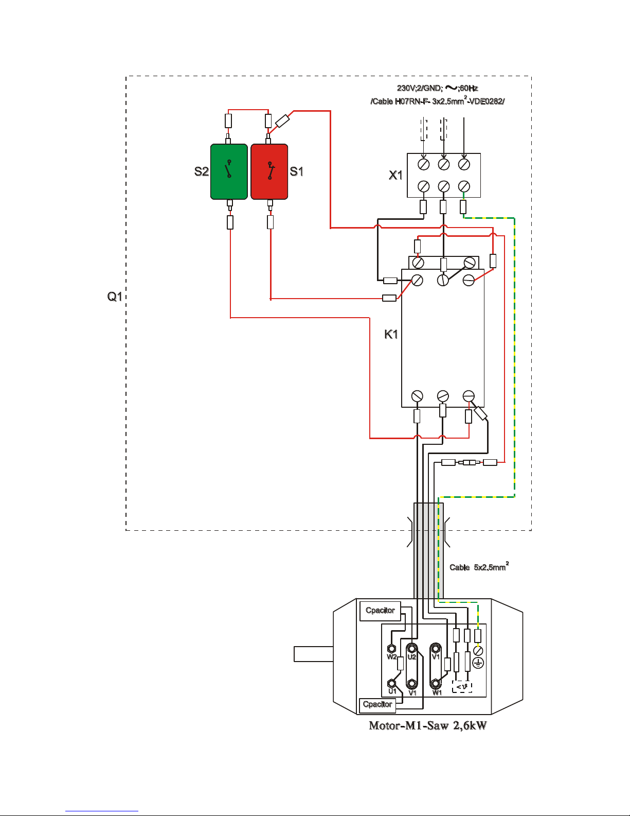
46
A1 A2
1L1 3L2 5L3
2T1 4T2 6T3
L1 L2 GND
POWER FROM WALL
Contactor
2
2
2
2
4
0
4
0
4
0
4
0
4
4
4
4
4
2
4
2
2
0
1
9
1
9
2
0
434
2
4
2
(Off-red)
P
E
(On-green)
Y
e
l
/
G
r
e
e
n
R
e
d
R
e
d
R
e
d
R
e
d
Red
B
l
a
c
k
B
l
a
c
k
R
e
d
B
l
a
c
k
B
l
a
c
k
R
e
d
B
l
a
c
k
Yel/Green
40A
Red
P
E
44 43
Page 47
47
A1 A2
1L1 3L2 5L3
2T1 4T2 6T3
L1 L2 GND
POWER FROM WALL
Contactor
Switch
2
2
2
2
4
0
4
0
4
0
4
0
4
4
4
4
4
2
4
2
2
0
1
9
1
9
2
4
2
0
2
5
4
3
4
3
4
2
4
4
4
2
1
3
2
4
(Off-red)
19
20
1
9
2
0
24
25
43
43
44
P
E
(On-green)
Y
e
l
/
G
r
e
e
n
Y
e
l
/
G
r
e
e
n
R
e
d
R
e
d
R
e
d
R
e
d
Red
Red
B
l
a
c
k
B
l
a
c
k
R
e
d
Black
Black Black
B
l
a
c
k
B
l
a
c
k
R
e
d
B
l
a
c
k
Yel/Green
Yel/Green
Black
Black
Black
Black
40A
Red
44
P
E
P
E
P
E
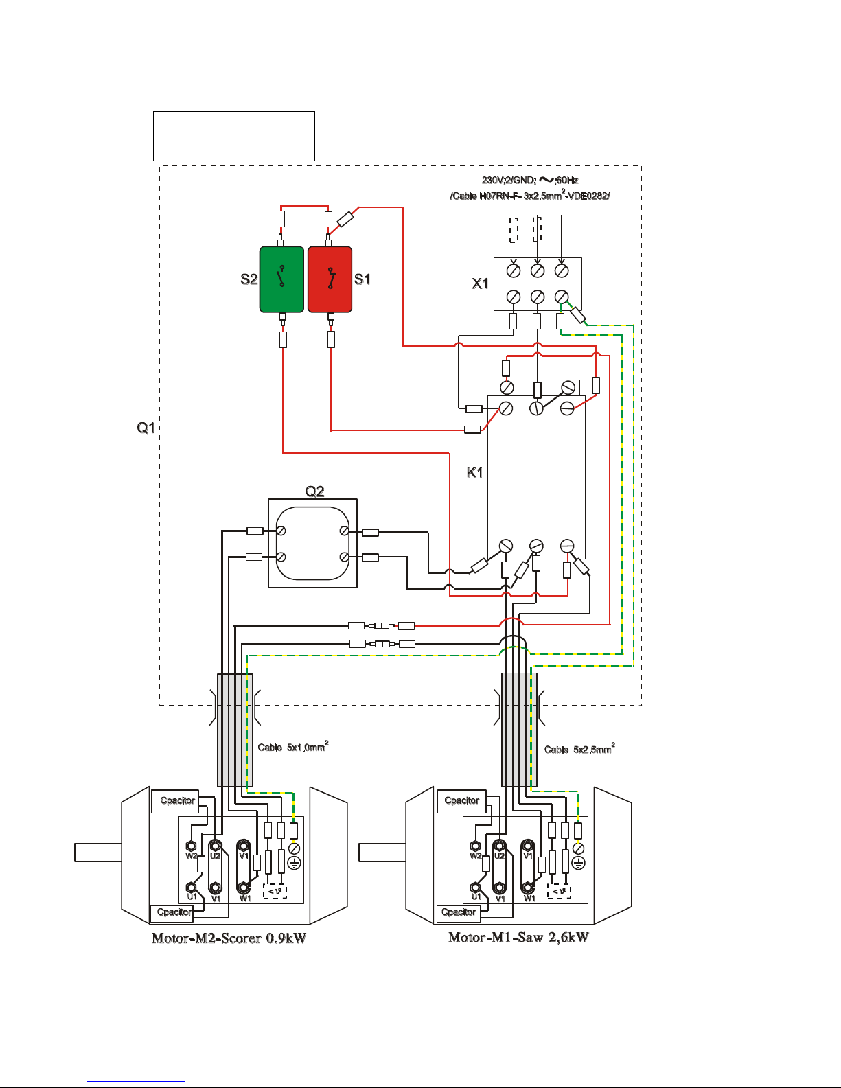
Electrical diagram
with scoring
Page 48

48
Parts breakdown for the TSS and TS table saws.
Note. Some parts shown in this manual may vary with the parts delivered with your
machine. We are constantly up grading the design of the machine and reserve the
right to change the machine and / or the specification with out notice.
Ordering spare-parts
When ordering spare parts specify:
Machine Model and serial number.
Part number required, taken from the exploded view drawing on the following page.
Quantity required
EXAMPLE: TO ORDER. Scoring electrical motor
Model :TSS
Serial number 12345
Description: Scoring electrical motor.
Part number: T80-2
Quantity: 1 piece
Page 49
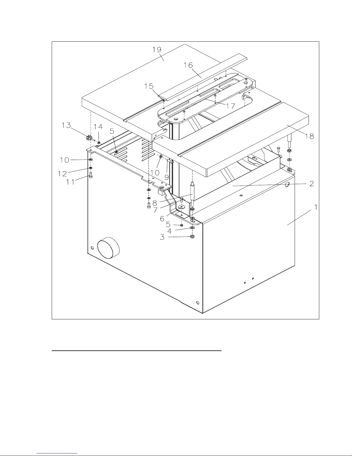
49
BODY WITH PANEL AND REMOVABLE PANEL [TS]
Page 50

50
BODY WITH PANEL AND REMOVABLE PANEL [TS]
1
ST-01.01.01.00.00
BODY
1
2
PS.00.00.09
SAFETY DEVICE
1
3
DIN 985
NUT М12 DIN
4
4
206-83
PULLEY АМ12
4
5
DIN 985
NUT М8 DIN
4
6
UN 732
PULLEY Ф9ХФ35Ф2,5
4
7
1234-85
BOLT М8Х25
2
8
PS.00.00.03
STUD M12
2
9
2171-83
SCREW М10Х30
2
10
206-83
PULLEY АМ10
6
11
2171-83
SCREW М10Х25
4
12
833-82
SPRING PULLEY 10Н
4
13
GN6336-4-SK-40-M8-30
HANDLE М8Х30
2
14
206-83
PULLEY АМ8
2
15
DIN 914
STOP SCREW М8Х10
8
16
PS.00.02.03
INSERT
1
17
PS.00.02.01
PAD
1
18
PS.00.00.01
REMOVABLE PANEL
1
19
ST-01.01.00.00.02
PANEL
1
Page 51
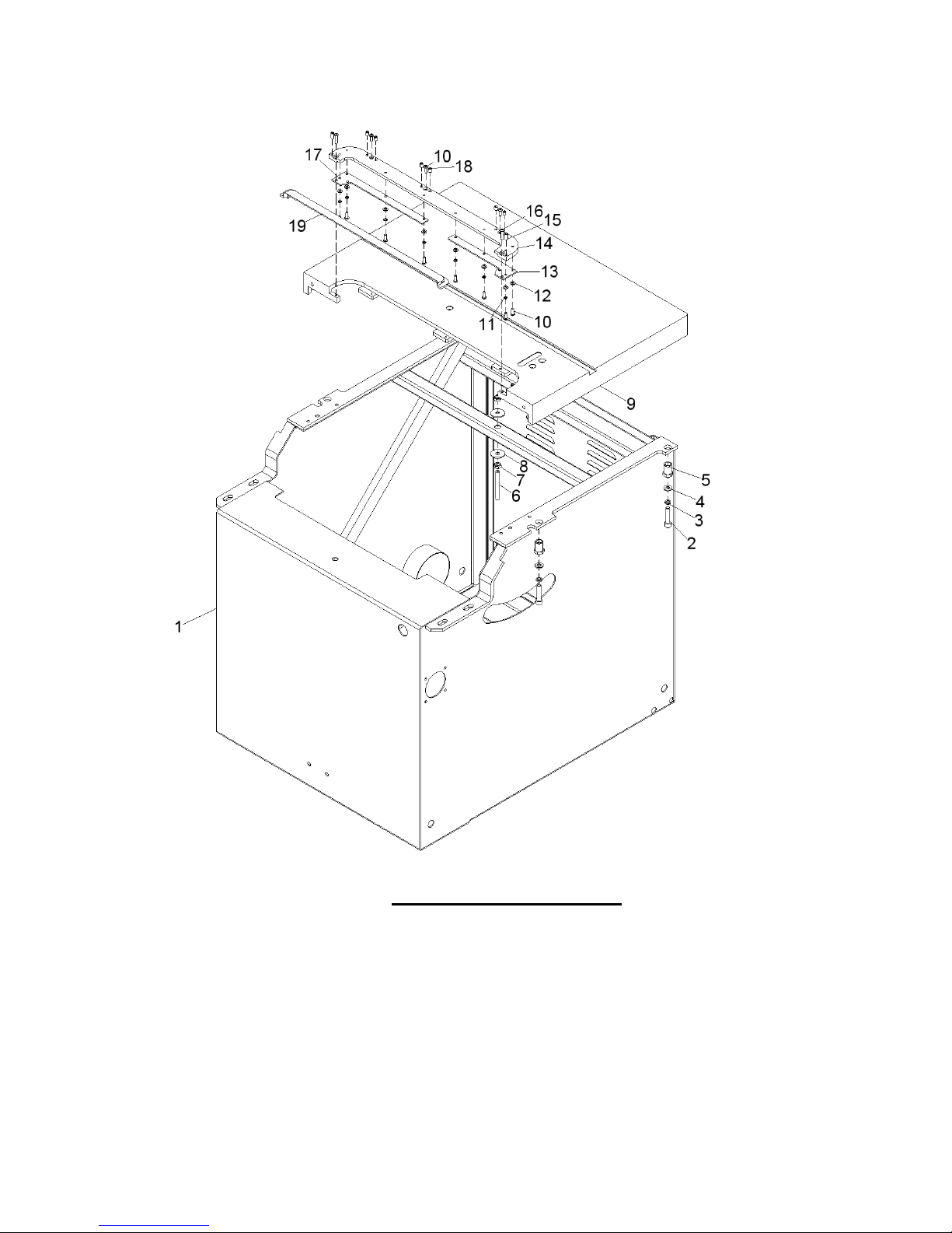
51
BODY WITH PANEL [TSS]
Page 52

52
1
ST01.01.01.00.00
BODY
1
2
DIN 912
SCREW М10X45
4
3
BDS 833-82
SPRING PULLEY 10Н
4
4
BDS 206-78
PULLEY АМ10
4 5 ST01.01.00.00.13
BOLT
4
6
ST01.01.00.00.14
STUD
1
7
BDS 744-83
NUT М10
1
8
UN732
PULLEY Ф35ХФ10Х2.5
2 9 ST01-01.00.00.02
PANEL
1
10
ISO 7380
SCREW М6Х16
11
11
BDS 833-82
SPRING PULLEY 6Н
8
12
BDS 206-78
PULLEY АМ 6
8
13
MF1270.00.01.01.03
PLATE
1
14
MF1270.00.01.01.01
PAD
1
15
DIN 913
STOP SCREW М 8Х16
2
16
ISO 7380
SCREW М6Х25
2
17
MF1270.00.01.01.02
PLATE
1
18
DIN 913
STOP SCREW М 8Х10
6
19
MF1270.00.01.02.00
INSERT
1
MF1270.00.01.03.00
INSERT - DADO
1
BODY WITH PANEL [TSS]
Page 53
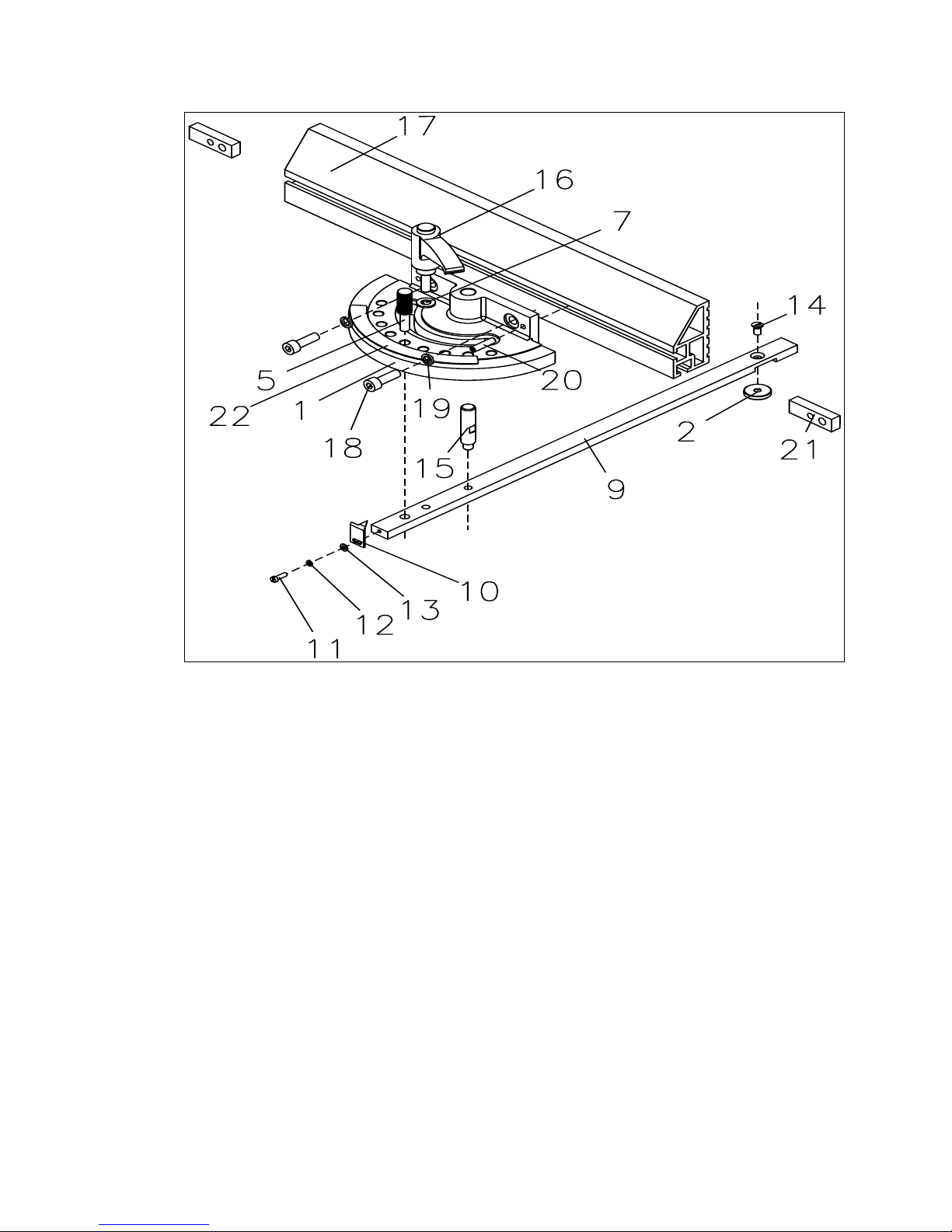
53
LNR 460.00.00.00 Crosscut fence [Optional 18” long]
1
LNR 230.00.00.07
Rotating body
1
2
LNR 230.00.09.03
Special nut
1
5
LNR 230.00.00.04
Pin
1
7
BDS 206-83
Pulley АМ8
1
9
LNR 230.00.09.01
Strap
1
10
LNR 230.00.00.03
Narrow
1
11
BDS 832-83
Screw М4Х12
1
12
BDS 833-82
Spring pulley 4N
1
13
BDS 206-83
Pulley АМ4
1
14
DIN 7991 8.8
Screw М6Х8
1
15
DM5
321.05П.00.01
Axis
1
16
GN603-63-M8-25DGN
Handle М8Х25
1
17
LNR 460.00.00.14
Fence
1
18
BDS 2171-83
Screw М8Х25
2
19
BDS 833-82
Spring pulley 2-8Н
2
20
DIN 913 45H
Screw М6Х25
1
21
LNR 230.00.00.13
Cotter
2
22
LNR 230.00.00.10
Scale
1
Page 54
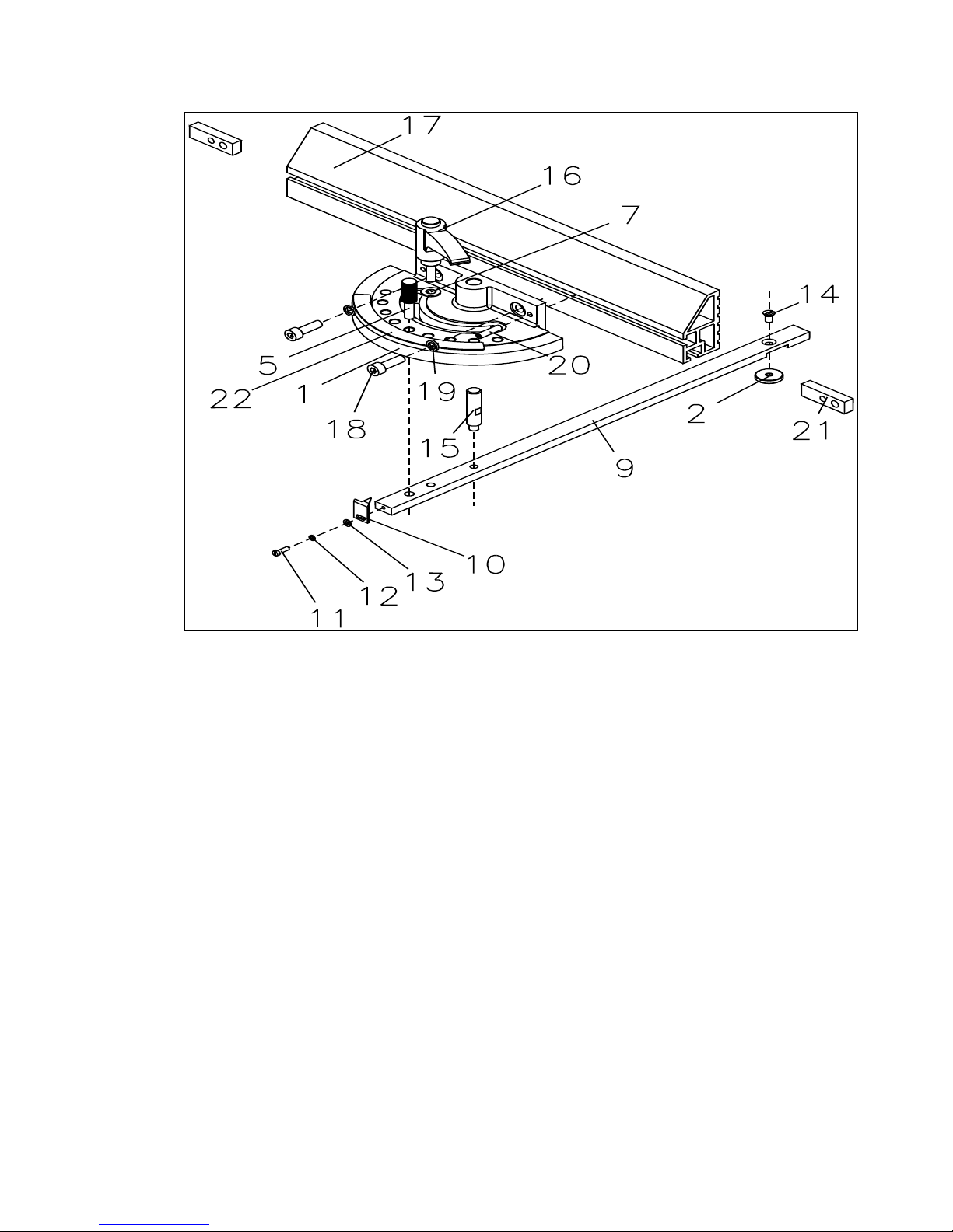
54
LNR 230.00.00.00 Crosscut fence [Optional 9” long]
1
LNR 230.00.00.07
Rotating body
1
2
LNR 230.00.09.03
Special nut
1
5
LNR 230.00.00.04
Pin
1
7
BDS 206-83
Pulley АМ8
1
9
LNR 230.00.09.01
Strip
1
10
LNR 230.00.00.03
Arrow
1
11
BDS 832-83
Screw М4Х12
1
12
BDS 833-82
Spring pulley 4N
1
13
BDS 206-83
Pulley АМ4
1
14
DIN 7991 8.8
Screw М6Х8
1
15
DM5
321.05П.00.01
Axis
1
16
GN603-63-M8-25DGN
Handle М8Х25
1
17
LNR 230.00.00.14
Fence
1
18
BDS 2171-83
Screw М8Х25
2
19
BDS 833-82
Spring pulley 2-8N
2
20
DIN 913 45H
Screw М6Х25
1
21
LNR 230.00.00.13
Cotter
2
22
LNR 230.00.00.10
Scale
1
Page 55
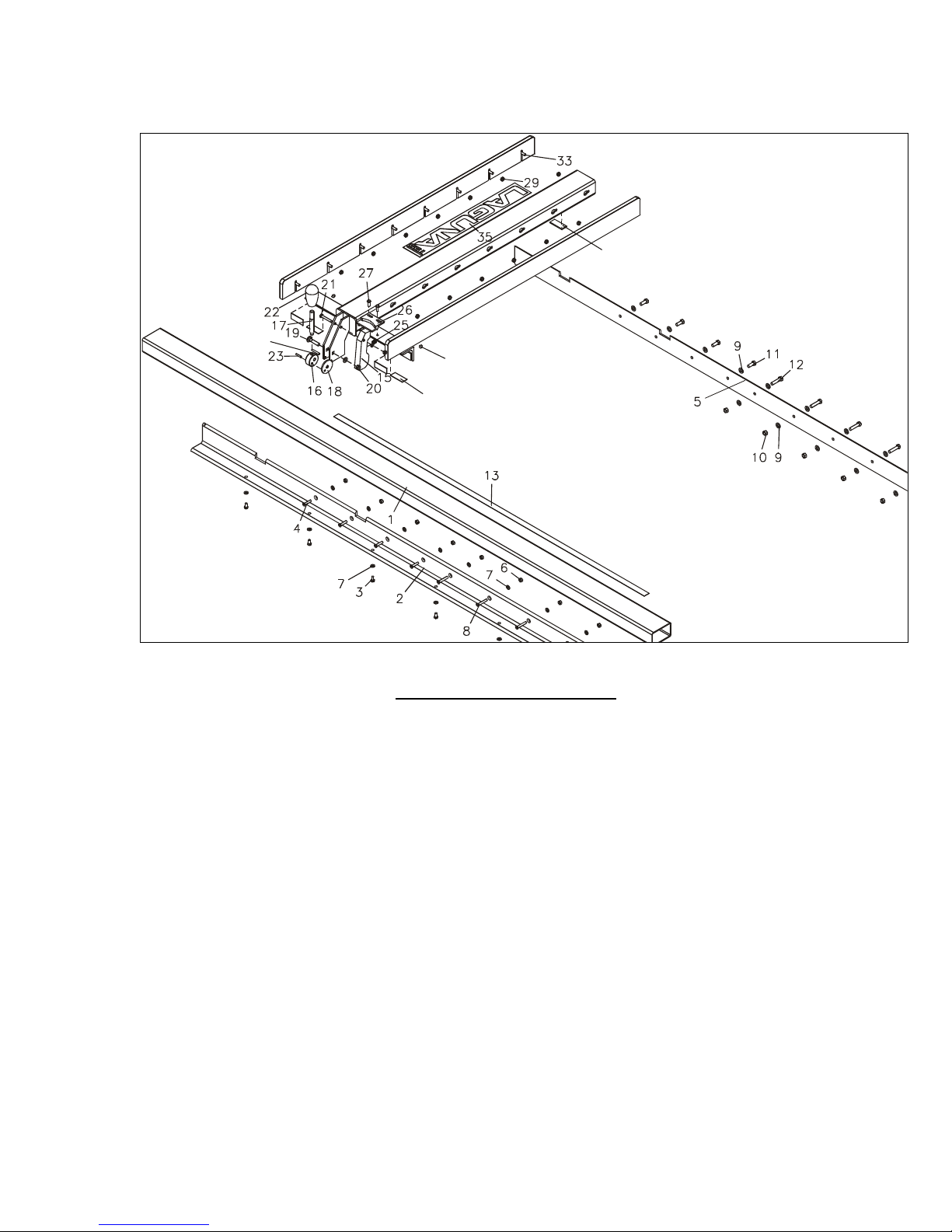
55
34
36
37
38
LU.00.00.00 Rip fence [TS]
Page 56

56
1
LU.00.00.09
GUIDE PIPE
1
2
LU.00.00.07
CARRYING SQUARE
1
3
BDS 1234-85
BOLT М6Х14
7
4
DIN 965A
SCREW М6Х25
4
5
LU.00.00.01
REAR CARRYING
SQUARE
1
6
BDS 744-83
NUT М6
9
7
BDS 206-83
WASHER АМ6
17
8
DIN 965A
SCREW М6Х35
6
9
BDS 206-83
WASHER АМ8
17
10
BDS 744-83
NUT М8
6
11
BDS 1234-83
BOLT М8Х20
4
12
BDS 1234-83
BOLT М8Х35
6
13
LU.00.00.10
RULE 0-53" (T 443)
1
14
LU.11.01.00
FENCE BODY
1
15
LU.11.00.08
TIGHTEN ARM
1
16
LU.11.00.12
ECCENTRIC
1
17
LU.11.00.17
STUD
1
18
LU.11.00.13
ECCENTRIC WASHER
1
19
DIN 603
SCREW М8Х45
1
20
DIN 985
NUT М8
1
21
BDS 1234-85
BOLT М6Х40
1
22
GN719-38M12
HANDLE
1
23
DIN 1481
SPRING PIN Ф4Х20
1
24
LU.11.00.02
LAMINATED FENCE
2
25
LU.11.00.07
SPRING
1
26
LU.11.05.00
POINTER
1
27
ISO 7380
SCREW М6Х10
2
29
DIN 985
NUT М6
17
33
DIN 603
SCREW М6Х20
16
34
DIN 1483
SPRING PIN Ф5Х30
1
35
LU.00.00.15
SIGN LAGUNA TS
(T467)
1
36
DIN 913
STOP SCREW M8X10
2
37
LU.11.01.07
PAD S=1 MM
4
38
LU.11.01.11
PAD S=3 MM
1
LU.00.00.00 Rip fence [TS]
Page 57
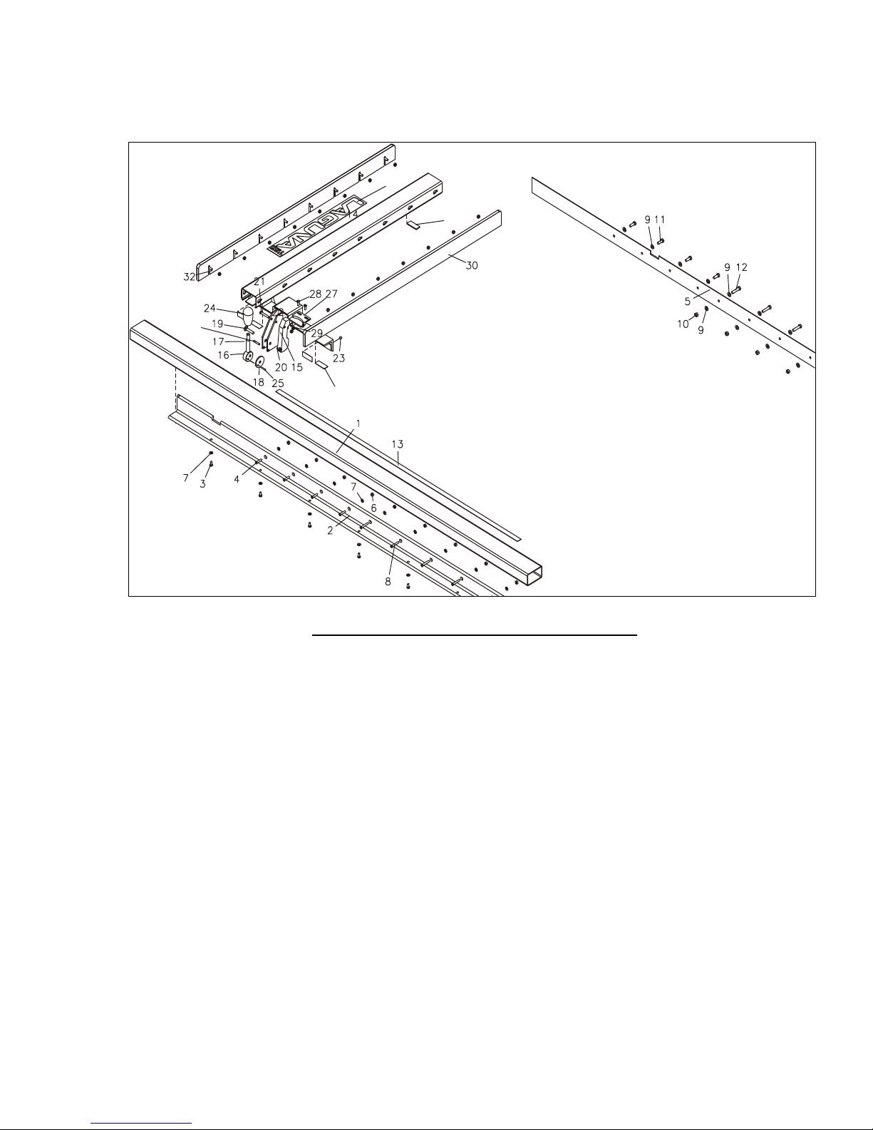
57
34
35
33
36
LUMF.00.00.00 Sliding table rip fence [TSS]
Page 58

58
1
LUMF.00.00.09
GUIDE PIPE
1
2
LUMF.00.00.07
CARRYING SQUARE
1
3
BDS 1230-85
BOLT М6Х14
6
4
DIN 965A
SCREW М6Х25
4
5
LUMF.00.00.01
REAR CARRYING SQUARE
1
6
BDS 744-83
NUT М6
9
7
BDS 206-83
WASHER АМ6
16
8
DIN 965A
SCREW М6Х35
6
9
BDS 206-83
WASHER АМ8
17
10
BDS 744-83
NUT М8
6
11
BDS 1234-83
BOLT М8Х20
4
12
BDS 1234-83
BOLT М8Х35
6
13
LU.00.00.10
RULE 0-53" (T 443)
1
14
LUMF.11.01.00
FENCE BODY
1
15
LU.11.00.08
TIGHTEN ARM
1
16
LU.11.00.12
ECCENTRIC
1
17
LU.11.00.17
STUD
1
18
LU.11.00.13
ECCENTRIC WASHER
1
19
DIN 603
SCREW М8Х45
1
20
DIN 985
NUT М8
1
21
BDS 1234-85
BOLT М6Х40
1
22
DIN 985
NUT M6
17
23
DIN 913
STOP SCREW M8X10
2
24
GN719-38-M12
HANDLE
1
25
DIN 1481
SPRING PIN Ф4Х20
1
27
LU.11.05.00
POINTER
1
28
ISO 7380
SCREW М6Х10
2
29
LU.11.00.07
SPRING
1
30
LU.11.00.02
LAMINATED FENCE
2
32
DIN 603
SCREW М6Х20
16
33
LUMF.00.00.15
SIGN LAGUNA TSS (T 535)
1
34
DIN 1483
SPRING PIN Ф5Х30
1
35
LU.11.01.07
PAD S=1 MM
4
36
LU.11.01.11
PAD S=3 MM
1
LUMF.00.00.00 Sliding table rip fence [TSS]
Page 59
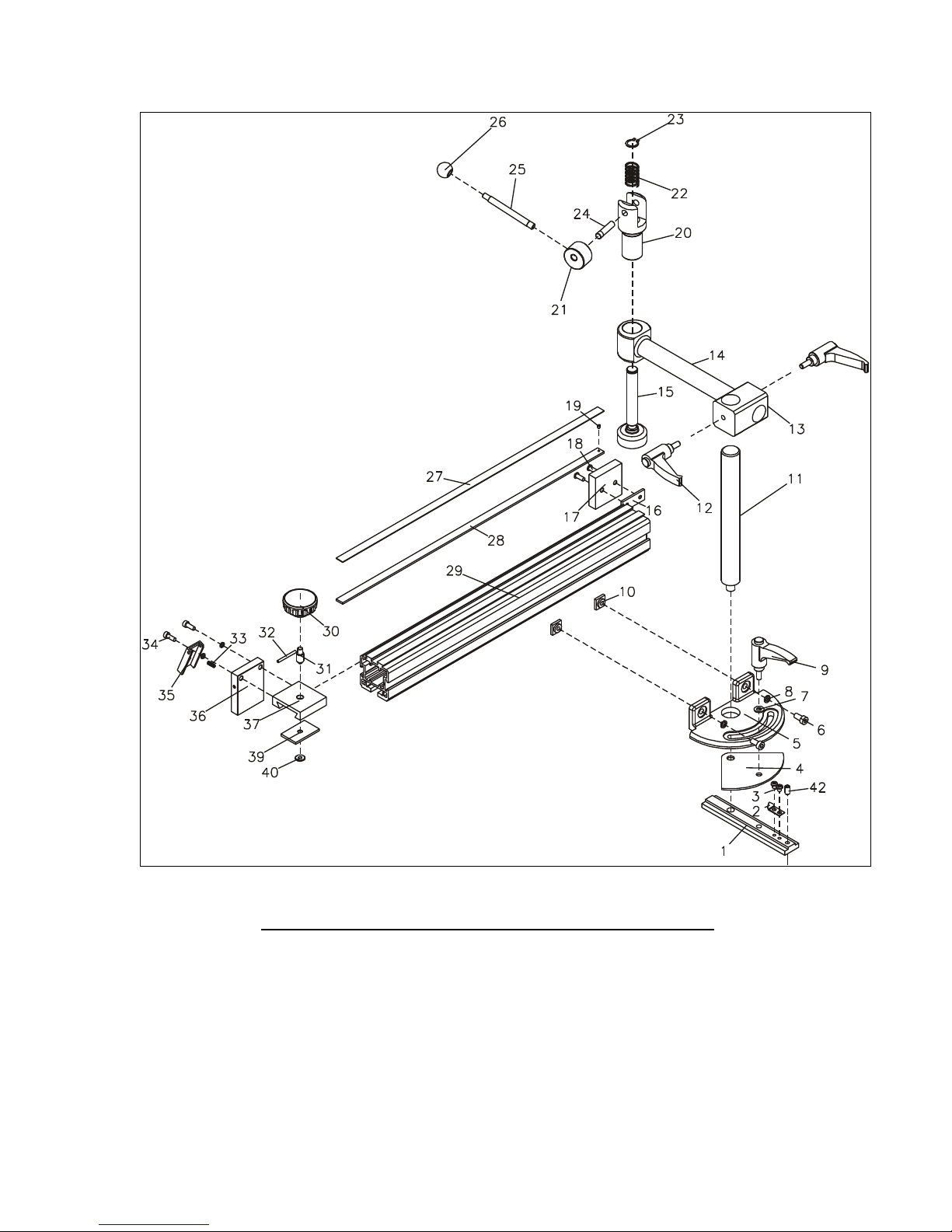
59
LVC1219 – 00.00.00 CIRCULAR SAW MITER FENCE
[TSS 4’ LONG]
Page 60

60
LVC1219 – 00.00.00 CIRCULAR SAW MITER FENCE
1
LVC600-00.00.02
COTTER
1
2
LVC600-00.00.05
ARROW
1
3
UN 6404
SCREW М6Х6
2
4
LVC600-00.00.03
LAMINATED FABRIC PAD
1
5
LVC600-00.00.04
BASIS
1
6
DIN 912 8.8
SCREW М8Х16
2
7
DIN 134
PULLEY ø10,5 xø22 x 2,5
1
8
DIN 127B
PULLEY 2-8H
2
9
GN603-78-M10-20-DGR
HANDLE М10Х20
1
10
LVC600-00.00.28
SQUARED COTTER
2
11
LVC600.11.00.10
COLOMN
1
12
GN603-63-M8-30-DGR
HANDLE М8Х30
2
13
LVF 00.11.00.12
BODY
1
14
LVF 00.11.02.00-01
ARM
1
15
LVF.00.11.01.00
SUPPORT
1
16
LVF 00.01.00.29
THRUST STRIP
1
17
LVF 00.01.00.31
WOODEN BLOCK
1
18
DIN 7380
SCREW М6Х16
2
19
DIN 551
STOP SCREW М4Х5 POLYAMIDE
1
20
LVF 00.11.00.04
GUIDE
1
21
S2300.10.00.00.03
ECCENTRIC
1
22
DM5-321.40.30.14
SPRING
1
23
BDS 2170-77
RING В18
1
24
LVF.00.11.00.10
AXIS
1
25
S2300.10.00.00.02
STUD
1
26
DIN319 KU-25-M8
BALL 25
1
27
Т480
RULLER 60-1300 D-L
1
28
LVC1219-00.00.26
STRIP /BAND/ 15x3, L=1219mm
1
29
LVC1219-00.00.01
PROFILE L=1219mm
1
30
DIN 6336-KU-50-M8
STAR HANDLE М8
1
31
S2300.13.00.00.19
SCREW
1
32
DIN 1481
PIN Ф4Х40
1
33
S2300.13.00.00.12
SPRING
1
34
DIN 912
SCREW М6Х16
2
35
S2300.13.00.00.13
STOP
1
36
S2300.13.00.00.11
STRIP
1
37
S2300.13.00.00.21
STRIP
1
39
S2300.13.00.00.17
STRIP
1
40
S2300.13.00.00.18
PULLEY
1
42
DIN 915
SCREW М8Х16
1
[TSS 4’ LONG]
Page 61
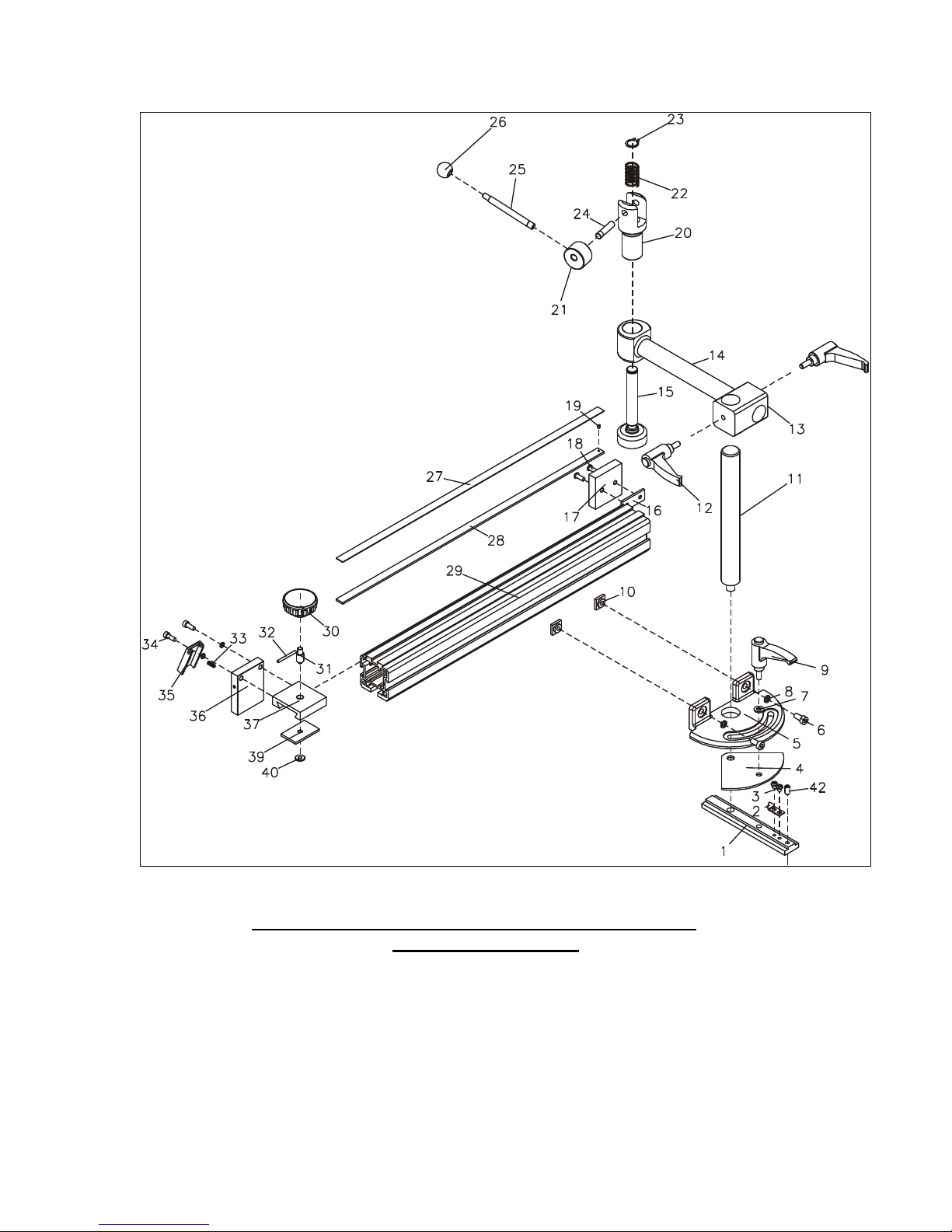
61
LVC600 – 00.00.00 CIRCULAR SAW MITER FENCE
[OPTIONAL 2’LONG]
Page 62

62
1
LVC600-00.00.02
COTTER
1
2
LVC600-00.00.05
ARROW
1
3
UN 6404
SCREW М6Х6
2
4
LVC600-00.00.03
LAMINATED FABRIC PAD
1
5
LVC600-00.00.04
BASIS
1
6
DIN 912 8.8
SCREW М8Х16
2
7
DIN 134
PULLEY ø10,5 xø22 x 2,5
1
8
DIN 127B
PULLEY 2-8H
2
9
GN603-78-M10-30-DGR
HANDLE М10Х30
1
10
LVC600-00.00.28
SQUARED COTTER
2
11
LVC600.11.00.10
COLOMN
1
12
GN603-63-M8-20-DGR
HANDLE М8Х20
2
13
LVF 00.11.00.12
BODY
1
14
LVF 00.11.02.00-01
ARM
1
15
LVF.00.11.01.00
SUPPORT
1
16
LVF 00.01.00.29
THRUST STRIP
1
17
LVF 00.01.00.31
WOODEN BLOCK
1
18
DIN 7380
SCREW М6Х16
2
19
DIN 551
STOP SCREW М4Х5 POLYAMIDE
1
20
LVF 00.11.00.04
GUIDE
1
21
S2300.10.00.00.03
ECCENTRIC
1
22
DM5-321.40.30.14
SPRING
1
23
BDS 2170-77
RING В18
1
24
LVF.00.11.00.10
AXIS
1
25
S2300.10.00.00.02
STUD
1
26
DIN319 KU-25-M8
BALL 25
1
27
Т480
RULLER 60-700 D-L
1
28
LVC600-00.00.26
STRIP /BAND/ 15x3, L=600 mm
1
29
LVC600-00.00.01
PROFILE L=600 mm
1
30
DIN6336-KU-50-M8
STAR HANDLE М8
1
31
S2300.13.00.00.19
SCREW
1
32
DIN 1481
PIN Ф4Х40
1
33
S2300.13.00.00.12
SPRING
1
34
DIN 912
SCREW М6Х16
2
35
S2300.13.00.00.13
STOP
1
36
S2300.13.00.00.11
STRIP
1
37
S2300.13.00.00.21
STRIP
1
39
S2300.13.00.00.17
STRIP
1
40
S2300.13.00.00.18
PULLEY
1
42
DIN 915
SCREW М8 Х 16
1
LVC600 – 00.00.00 CIRCULAR SAW MITER FENCE
[OPTIONAL 2’ LONG]
Page 63
63
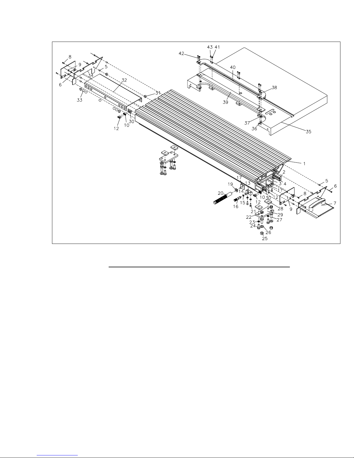
MF1270.03.00.00.00 SLIDING TABLE (MF) L=1270 [TSS]
Page 64

64
MF1270.03.00.00.00 SLIDING TABLE (MF) L=1270 [TSS]
1
S1270.03.00.00.01
SLIDING TABLE MOVABLE PART
1
2
S1270.03.00.00.09
MOULDING
2
3
S1270.03.00.00.11
SLIDING TABLE IMMOVABLE PART
1
4
S1270.03.00.00.06
GUIDE
8
5
BDS 12620-75
DOWEL DS-3 (Ф8)
8
6
БДС 664-70
WOODEN SCREW 5Х45
8
7
S2300.09.02.01.00
SLIDING TABLE COVER
1
8
DIN 963A
SCREW М4Х12
6
9
S2300.09.00.00.03-01
COVER
2
10
БДС 833-82
SPRING PULLEY 6Н
6
11
S2300.03.00.00.12
COTTER
2
12
БДС 2171-83
SCREW М6Х12
8
13
S2300.04.00.00.10
GUIDE LOCK PIN
1
14
S2300.04.00.00.11
LOCK RING
1
15
БДС 7947-85
О-RING Ф8,5Х1,5
1
16
S2300.04.00.00.02-01
LOCK PIN
1
17
S2300.07.00.00.03
COTTER
1
19
S2300.07.00.00.02
PULLEY Ф24ХФ8,5Х3
1
20
S2300.07.00.00.01
HANDLE
1
21
БДС 2171-83
SCREW М6Х16
2
22
DIN 985-6
NUT М12 DIN 985
4
23
БДС 833-82
SPRING PULLEY 10N
4
24
БДС 1234-83
BOLT М10Х25
4
25
БДС 1250-83
NUT М12
4
26
S2300.05.00.00.04
THRUST WASHER
8
27
S2300.05.00.00.03-01
STUD М12Х60
4
28
S2300.05.00.02
COTTER
4
29
S3200.05.00.00.02
THRUST STRIP
2
30
S2300.03.00.14.00
STOP
2
31
S3200.03.00.00.06
CLEANER-FOG LUBRICATOR
4
32
S1150.03.00.00.03
SEPARATOR
1
33
БДС 4885-82
SHOT Ф15,081
10
34
S2300.09.00.00.01-01
TOP SLIDING TABLE COVER
1
35
ST-01.01.00.00.02
PANEL
1
36
ISO 7380
SCREW М6Х12
2
37
БДС 206-83
PULLEY АМ6
2
38
DIN 913
STOP SCREW М6Х18
2
39
МФ1270.00.01.00.02
МФ1270.00.01.00.03
INSERT
1
40
МФ1270.00.01.00.01
PAD
1
41
ISO 7380
SCREW М6Х16
3
42
ISO 7380
SCREW М6Х30
2
43
DIN 913
STOP SCREW М6Х10
3
Page 65
65
1
ST-
01.01.00.00.02
PANEL
1
2
BDS 206-83
PULLEY АМ12
2
3
BDS 1234-85
BOLT М12Х30
2
4
MUS.01.00.00
EXTENSION TABLE 800X900
1
5
DIN 913
STOP SCREW М6Х16
2
6
ОК.00.00
SUPPORT LEG
2
6
ОК.00.00
LEG
2
7
К34885
THRUST М8Х50
2
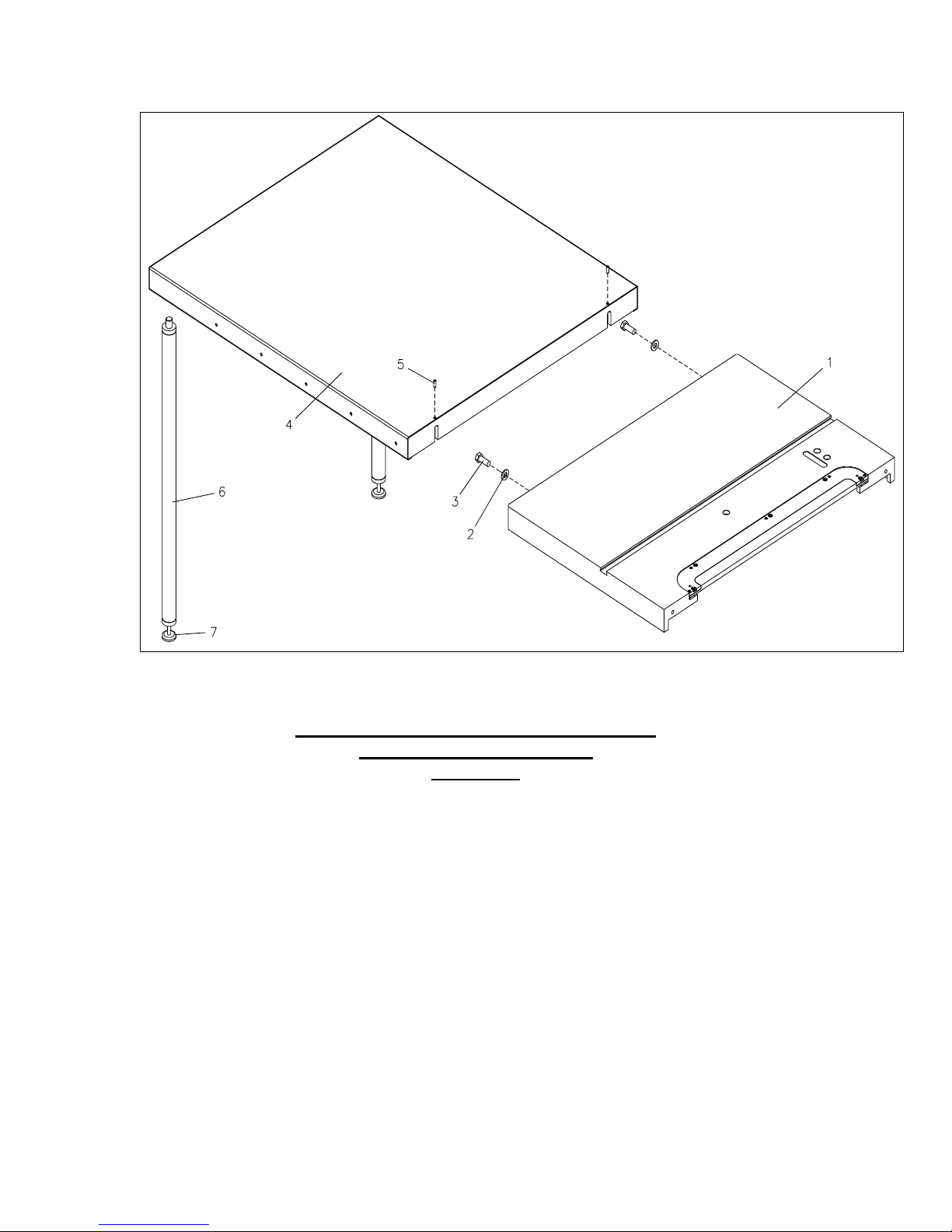
MUS.00.00.00 PLATE EXTENSION TABLE
ОК.00.00.00 SUPPORT LEG
[TSS &TS]
Page 66
66
44
45
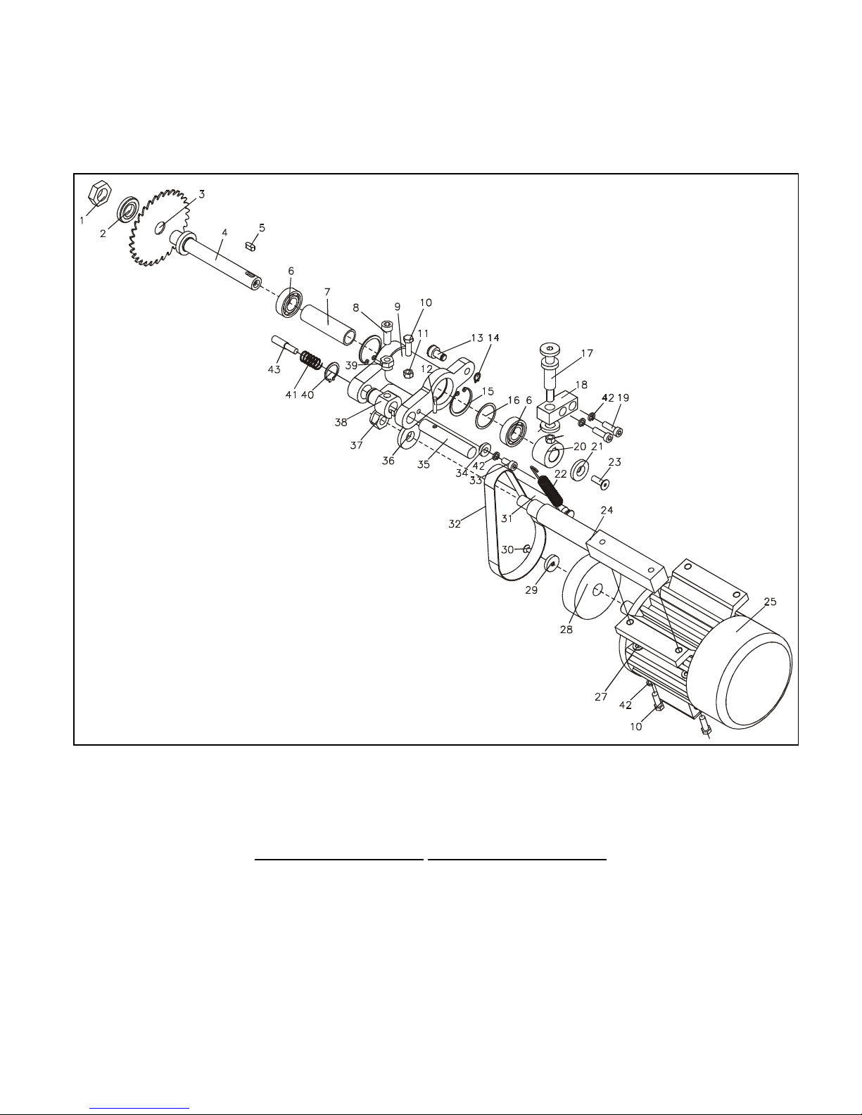
RC.00.00.00-T Scoring / [OPTIONAL TSS &TS]
Page 67

67
RC.00.00.00-T Scoring unit [OPTIONAL TSS & TS]
1
RC.00.00.12
NUT
1
2
RC.00.00.11
PRESSING PULLEY
1
3*
OPTIONAL
CIRCULAR SAW 120 Х 20 Х 2,5
1
4
RC.00.00.07
ARBOR
1
5
BDS 3389-83
STUD 1-6Х6Х16
1
6 BEARING 6004-2RS. C3
2
7
RC.00.00.06
BUSHING
1
8
BDS 2171-83
SCREW М10Х25
1
9
RC.00.00.15
AXLE BOX
1
10
BDS 1234-85
BOLT М8Х25
3
11
BDS 744-83
NUT М8
1
12
S2300.28.00.00.16
PIN
1
13
RC.00.00.38
ROLLER
1
14
BDS 2170-77
LOCK RING В10
1
15
BDS 2170-77
LOCK RING А42
2
16 ADJUSTING PULLEY Ф41ХФ34,5Х0,35
1
17
RC.00.00.16-01
SCREW-LIFTING
1
18
RC.00.00.36
LIFTING BLOCK
1
19
BDS 2171-83
SCREW М8Х25
2
20
S2300.28.00.00.20
BELT PULLEY
1
21
S2300.28.00.00.19
PULLEY
1
22
RC.00.00.17
SPRING
1
23
DIN 7991
SCREW М8 Х 20
1
24
RC.00.00.01
MOTOR AXIS
1
25
Т 80А-2
MOTOR
1
27
BDS 206-83
WASHER АМ8
2
28
RC.00.00.25
BELT PULLEY /RIGGER/
1
29
RC.00.00.34
PULLEY
1
30
DIN 7991
SCREW М6Х16
1
31
RC.00.00.40
STUD
1
32 Flat belt 1.25Х20, L=510mm
1
33
BDS 2171-83
SCREW М8Х16
1
34
RC.00.00.04
LIMITING WASHER
1
35
RC.00.00.05
AXIS
1
36
DIN 7349
PULLEY Ф17 ХФ40 Х6
1
37
DIN 985
NUT М16
1
38
RC.00.00.19
GUIDE
1
39
RC.00.00.23
SPECIAL NUT
1
40
BDS 2170-77
LOCK RING В22
1
41
ADM410.20.00.106
SPRING
1
42
BDS 833-82
SPRING PULLEY 2-8H
5
43
RC.00.00.18
SCREW-MOVING
1
44
BDS 206-83
WASHER AM10
1
45
DIN 985
NUT М10
1
Page 68
68
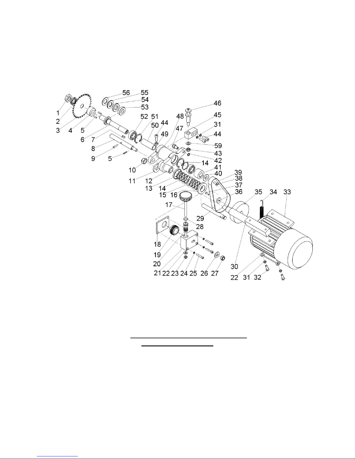
RCD 00.00.00 Scoring unit with DADO
[OPTIONAL TSS &TS]
Page 69

69
Pos.
Description
Name
Quan
tity
1.
RC 00.00.12
Nut
1
2.
RC 00.00.11
Pressing pulley
1
3.*
Circular disk ø120 x ø20 x 2
1
4.
RCD 00.00.04
Support
1
5.
DIN 1481
Spring pin ø5 x 18
3
6.
RCD 00.00.06
Shaft
1
7.
DIN6885 A
Feather 1-6x6x16
1
8.
RCD 00.00.08
Guiding axis
1
9.
S3200.28.00.00.16
Pin
1
10.
DIN 985
Nut M16
1
11.
DIN 7349
Pulley M16
1
12.
RCD 00.00.12
Guide
1
13.
S400-28.00.00.52
Small insertion
1
14.
Leveling pulley 40
9
15.
DIN988
Pulley ø30x ø42 x 1
1
16.
S400-28.00.00.53
Big insertion
1
17.
S2300.28.00.02.00
Handle
2
18.
S3200.28.00.00.19
Cover
1
19.
S3200.28.00.36
Worm- wheel
1
20.
S2300.28.00.00.08-01
Worm
1
21.
S3200.28.00.00.20
Corpus
1
22.
DIN134
Pulley M8
3
23.
DIN 985
Nut M8
1
24.
BDS833-82
Pulley PR 2-6N
3
25.
DIN 912
Screw M 6x35
3
26.
DIN134
Pulley M12
1
27.
DIN 985
Nut M12
1
28.
BDS 7947-85
O- Ring ø16x2
1
29.
RC 00.00.40
Stud
1
30.
RC 00.00.01
Motor axis
1
31.
BDS833-82
Pulley PR 2-8N
4
32.
BDS1234-85
Bolt M 8x25
2
33.
Motor
1
34.
RC 00.00.17
Spring
1
RCD 00.00.00 Scoring unit with DADO [OPTIONAL TSS &TS]
Page 70

70
35.
RC 00.00.25
Belt pulley
1
36.
RC 00.00.34
Pulley
1
37.
BDS1359-83
Screw M 5x16
1
38.
DIN 7991
Screw M 8x20
1
39.
Belt 20 х 1, L=510
1
40.
S2300.28.00.00.19
Pulley
1
41.
S2300.28.00.00.20
Belt pulley
1
42.
DIN 471
Ring for shaft ø12
1
43.
DIN 985
Nut M10
1
44.
BDS2171-83
Screw M 8x25
3
45.
RC 00.00.36
Lifting block
1
46.
RCD 00.00.46
Lifting Screw
1
47.
RC 00.00.38
Roller
1
48.
RCD 00.00.48
Axle
1
49.
BDS744-83
Nut M8
1
50.
RCD 00.00.50
Buch
1
51.
DIN 472
Ring for opening ø42
2
52.
Bearing 6004.2RS.C3
2
53.*
RCD 00.60.04
Spacer 3/8"
1
54.*
RCD 00.60.03
Spacer 1/4"
1
55.*
RCD 00.60.02
Spacer 1/8"
1
56.*
RCD 00.60.01
Spacer 1/16"
1
* - By special request
Page 71
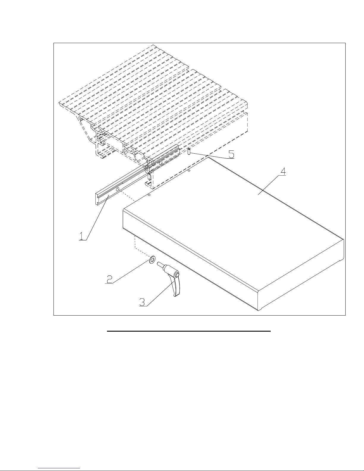
71
1
SF250M.08.00.00.01
SLIDE BLOCK
1
2
BDS 206-83
PULLEY АМ10
2
3
GN603-73-M10-20DGR
HANDLE
2
4
SF2300.15.01.00.00
EXTENSION TABLE 500Х320
1
5
BDS 1362-83
STOP SCREW М6Х16
2
SF 250M.08.00.00.00 BRACKET TABLE [TSS &TS]
Page 72
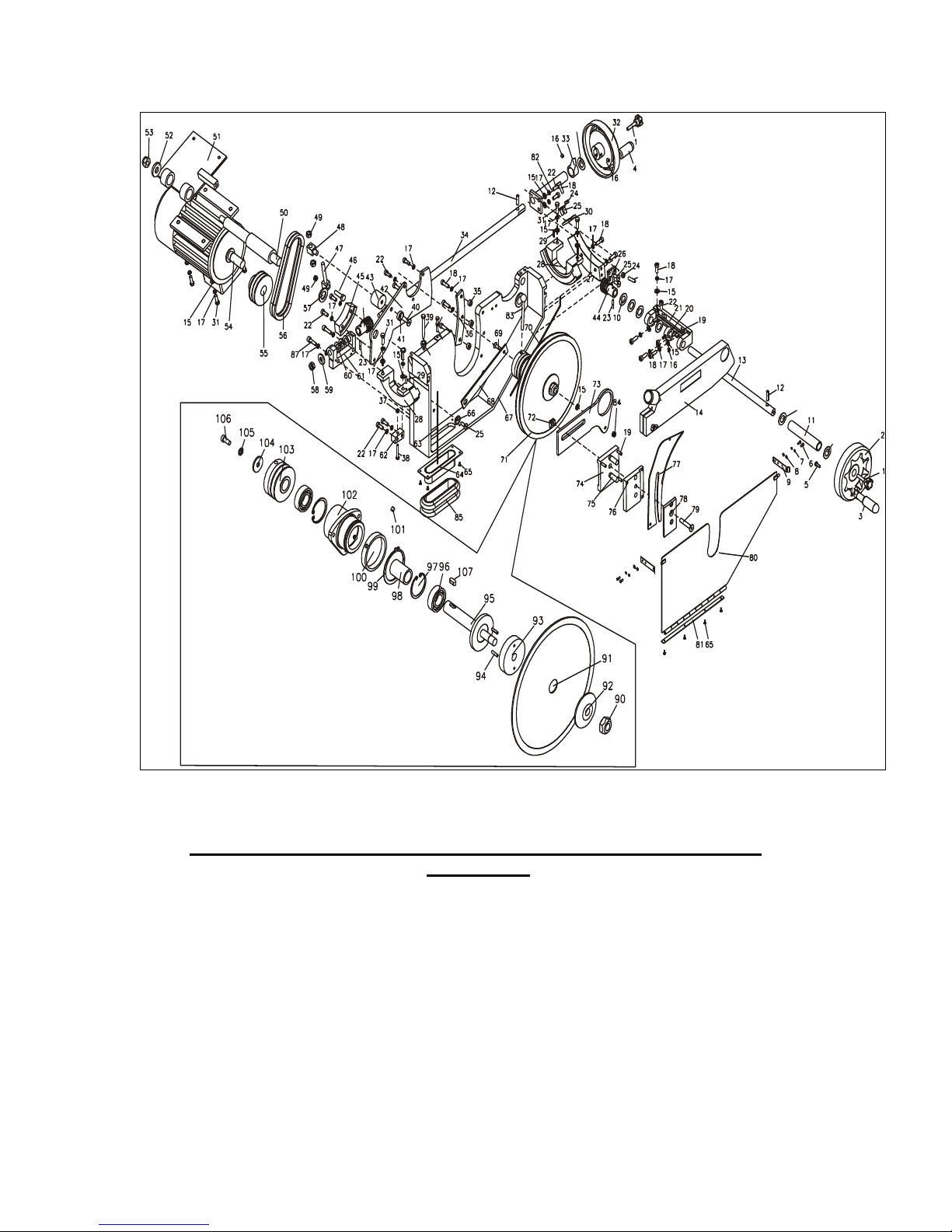
72
108
108
108
89
88
24
86
49
ST01-02.00.00.00 MAIN CIRCULAR SAW / 1-PHASE MOTOR 2,2kW
[TSS & TSS]
Page 73

73
ST01-02.00.00.00 MAIN CIRCULAR SAW / 1-PHASE MOTOR 2,2kW /
1
GN6336.4-ST-40-M8-40
HANDLE М8Х40
2
2
KRMC-ST 11.01
SMALL HAND WHEEL FOR FOLDING
HANDLE
1
3
GN 698.3-26-М6
FLYWHEEL HANDLE, BLACK
1
4
GN 698-KT-26-M10
FLYWHEEL HANDLE, BLACK
1
5
DIN7991
SCREW М6Х12
1
6
БДС 832-83
SCREW М4Х10
4
7
БДС 833-82
PULLEY 2-4Н
4
8
БДС 206-83
PULLEY АМ4
4
9
S2300.02.00.00.23
SPRING
2
10
AS 2035
AXIAL PULLEY 20Х35Х1
4
11
ST 01-02.00.00.88
BUSHING – TILTING
1
12
CRMSH 11.07
PIN Ф8Х32
2
13
ST 01-02.00.00.87
ARBOR – TILTING
1
14
ST 01-02.00.35.00
SAFETY DEVICE
1
15
BDS 206-83
PULLEY АМ8
16
16
DIN 913
STOP SCREW М8Х8
6
17
BDS 833-82
PULLEY 2-8Н
29
18
BDS 2171-83
SCREW М8Х25
11
19
DIN 913
STOP SCREW М6Х20
6
20
ST 01-02.00.00.50
THRUST RING
1
21
ST 01-02.00.00.89
BASIS FOR TILTING
1
22
BDS 2171-83
SCREW М8Х20
10
23
DIN 1481
PIN Ф5Х26
2
24
BDS 744-83
NUT М8
3
25
DIN 7991
SCREW М8Х16
5
26
ST 01-02.00.00.76
STOP 90º
1
27
ST 01-02.00.00.90
TILTING SECTOR
1
28
ST 01-02.00.00.32
SECTOR
2
29
DIN 1481
PIN Ф5Х20
4
30
ST 01-02.00.00.79
STOP 45º
1
31
DIN 933 8.8
BOLT М8Х25
8
32
KRM-ST11.01
SMALL HAND WHEEL
1
33
ST 01-02.00.24.00
ARROW
1
34
ST 01-02.00.00.22
ARBOR LIFTING
1
35
ST 01-02.00.00.16
BUSHING
3
36
ST 01-02.00.00.34
THRUST STRIP
1
37
BDS 744-83
NUT М6
1
38
BDS 1234-85
BOLT М6Х40
1
39
ST 01-02.00.00.46
STOP SCREW
1
40
DIN 7991 8.8
SCREW М10Х25
1
41
ST 01-02.00.00.44
PULLEY Ф10,5 Х Ф25Х8
1
42
ST 01-02.00.00.02
CRADLE
1
43
ST 01-02.00.00.42
THRUST BLOCK
1
44
ST 01-02.00.00.69
WORM TILTING
1
45
ST 01-02.00.00.03
SECTOR LIFTING
1
46
BDS 1234-85
BOLT М10Х40
1
47
ST 01-02.00.00.41
SPECIAL BOLT
1
48
ST 01-02.00.00.40
BLOCK
1
Page 74

74
49
BDS 744-83
NUT М10
2
50
ST 01-02.00.00.58
COLOMN
1
51
ST 01-02.00.59.00-02
MOTOR CRADLE / ESR 90L /
1
52
DIN 7349
PULLEY ø17 X ø 40 X 6
1
53
DIN 985
NUT М16
1
54 MOTOR
1
55
ST 01-02.00.00.63
BELT PULLEY
1
56 BELT SPZ 630 MN, Lp≈Ld≈Lw= 630mm
2
57
S2300.02.00.00.43
PULLEY Ф40ХФ24Х4
1
58
DIN 985
NUT М12
1
59
S2300.02.00.00.17
PULLEY
1
60
AS 1528
AXIAL PULLEY 15Х28Х1
3
61
S2300.02.00.00.08
BASIS LIFTING
1
62
S2300.02.00.00.09
BLOCK LIFTING
1
63
S2300.02.00.00.65
SHORT SEAL
1
64
S2300.02.00.86.00
ASPIRATING SHOE
1
65
DIN 7337A
RIVET Ф4Х8 ST/ST
8
66
S2300.02.00.00.81
STOP
1
67
S2300.02.00.00.01
BEAM
1
68
S2300.02.00.00.80
PANTOGRAPH STRAP
1
69
DIN 7991
SCREW М8Х25
1
70
S2300.02.00.00.66
SEALING
1
71
S2300.02.00.37.00
MAIN CIRCULAR SAW
1
72
S2300.02.00.00.52
COTTER
1
73
S2300.02.00.37.18
CARRIER
1
74
S2300.02.00.00.53
BACK STRAP
1
75
S2300.02.00.00.57
PIN 2 76
S2300.02.00.00.56
MIDDLE STRAP
1
77
S2300.02.00.00.38
RIVING KNIFE
1
78
S2300.02.00.00.55
FRONT STRAP
1
79
DIN 7991
SCREW М10Х52
1
80
S2300.02.00.68.00
VALVE
1
81
S2300.02.00.00.60
STABILIZE STRAP
1
82
S2300.02.00.23.00
GUIDE LIFTING
1
83
S2300.02.00.36.00
HANDLE WITH A BALL
1
84
DIN 985
NUT М8
1
85 ASPIRATING HOSE, L=1200mm
1
86
S2300.02.00.00.14
WORM LIFTING
1
87
BDS 2171-83
SCREW М8х30
2
88
DIN 933 8.8
BOLT M8X30
1
89
DIN 913 8.8
STOP SCREW M8X30
2
90
S2300.02.37.00.01
NUT
1
91* SAW BLADE ø12”
2
92
S2300.02.37.02.00
FLANGE EXTERIOR
1
93
S2300.02.37.00.04
STOP
1
94
DIN 1481
SPRING PIN Ф5Х20
2
95
S2300.02.37.06.00
ARBOR WITH FLANGE
1
96 BEARING 6205 2RS.С3
2
97
BDS 2170-77
LOCK RING А52
2
98
S2300.02.37.00.17
BUSHING REMOTE
1
Page 75
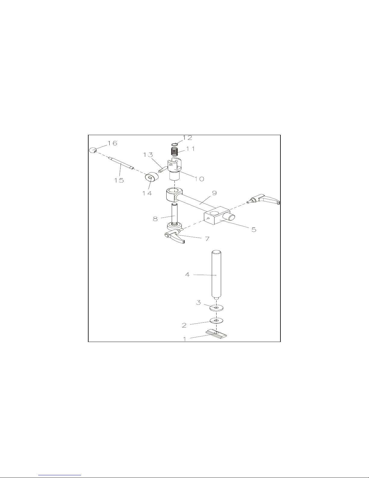
75
99
BDS 2170-77
RING В70
1
100
S2300.02.37.00.08
THRUST RING
1
101
DIN 913
SCREW М8Х8
2
102
S2300.02.37.00.10
CARRIER
1
103
S2300.02.37.00.13
BELT PULLEY
1
104
UN 732
PULLEY ø8 х ø35 х 2,5
1
105
BDS 833-82
PULLEY 2-8Н
1
106
BDS 2171-83
SCREW М8Х20
1
107
BDS 3389-83
COTTER 8Х7Х20
1
108
DIN 988
PULLEY ø20 х ø28 х 1
3
- by order
ST01-10.00.00 HOLD DOWN CLAMP
Page 76

76
[OPTIONAL TSS]
1
ST 01-10.00.03
COTTER
1
2
ST 01.10.00.04
PAD
1
3
ST 01-10.00.05
THRUST
1
4
LVC 600-00.00.10
COLOMN
1
5
LVF 00.11.00.12
BODY
1
7
GN603-63-M8-20-DGR
HANDLE М8Х20
2
8
LVF.00.11.01.00
SUPPORT
1
9
LVF 00.11.02.00-01
LEVER
1
10
LVF 00.11.00.04
GUIDE
1
11
DM5-321.40.30.14
SPRING
1
12
BDS 2170-77
RING В18
1
13
LVF.00.11.00.10
AXIS
1
14
S2300.10.00.00.03
ECCENTRIC
1
15
S2300.10.00.00.02
STUD
1
16
DIN319-KU-25-M8-C
BALL 25
1
Page 77
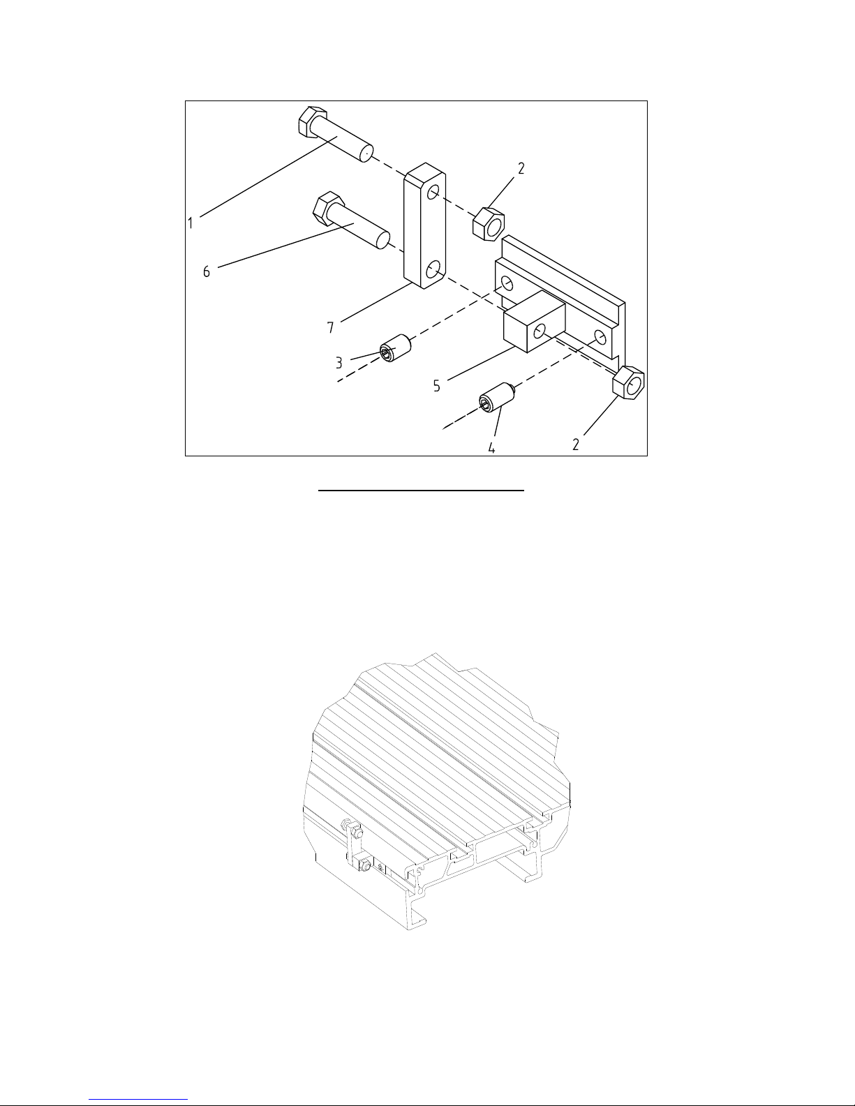
77
1.
U-00.00.01
THRUST BOLT
1
2.
BDS 744-83
NUT-М8
2
3.
DIN 913
SCREW М8Х12
1
4.
DIN 915
SCREW М8Х16
1
5.
У-00.04.00
BASIS
1
6.
BDS1230-85
BOLT М8Х30
1
7.
У-00.00.02
STRAP
1
U – 00.00.00 Stop 90° [TSS]
Page 78

2072 Alton Parkway. Irvine, CA 92606
Ph: 800.234.1976 | www.lagunatools.com
Laguna Tools is not responsible for errors or omissions.
Specifications subject to change. Machines may be shown with optional accessories.
© 2017, Laguna Tools, Inc. LAGUNA® and the LAGUNA Logo® are the
registered trademarks of Laguna Tools, Inc. All rights reserved.
 Loading...