

Page 1

Owner’s Manual
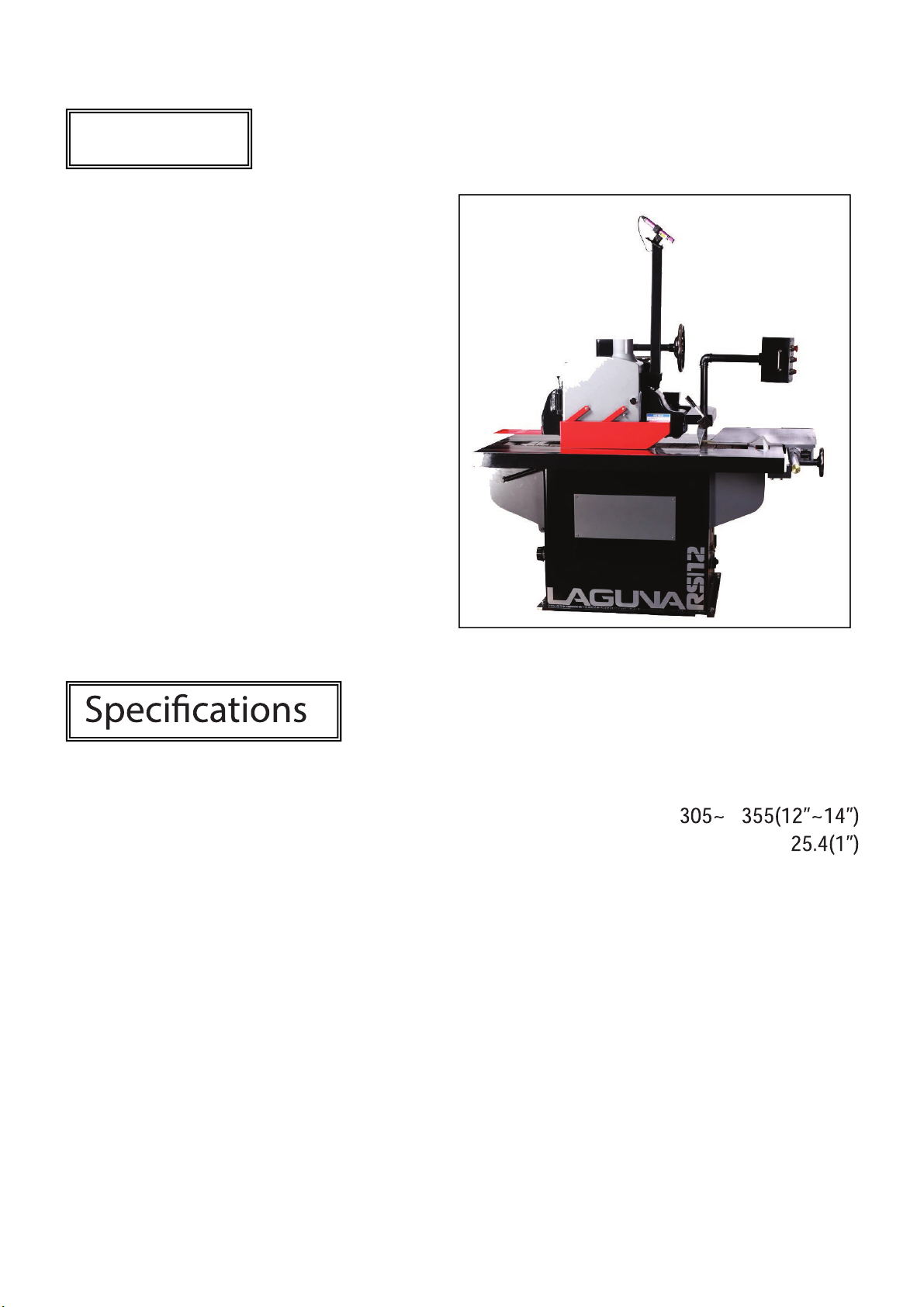
Straight Line Rip Saw
MRS5000-0280
lagunatools.com | lagunacleanair.com | supermaxtools.com
Page 2
Features
• Precision fence locks securely and
accurate parallelism to the
• Double anti-kick fingers for
maximum safety.
• Ruggedly constructed frame,
massive table
• Precision built saw head assembly
assures absolute straign line rip
saw operation.
• Easy quick change for speeds feed.
• Precision built V-way track assures
absolute straight line up saw
operations.
• Automatic lubrication to V-way track
facilitate chains smooth running.
Arbor motor 7.5 HP / 10 HP / 15 HP
Saw blade diameter
Saw arbor diameter
Working thickness 100 mm
Hold down rollers 5
Distance between saw & column 460 mm
Spindle rotation (50Hz) 3600 R.P.M
Spindle rotation (60Hz) 4500 R.P.M
Feeding motor 1 HP / 2 HP
Feeding speed (50Hz) 11~45 m/ min (15 / 20 / 25 / 30 m/min)
Feeding speed (60Hz) 13~31 m/ min (15 / 20 / 25 / 30 m/min)
Table area 900 x 1450 mm
Net weight 900 kgs
Gross weight 1150 kgs
Packing size 1550 x 1130 x 1700 mm
Page 3

General safety rules
1. Know your machine. Read this operation manual carefully. Learn t
machine application and limition, as well as the specic potential hazards
peculiar to it.
2. Keep guards in place and in working order.
3. The machine must be properly grounded to prevent electric shock.
4. Keep chil
. Don’t use in dangerous environment. Don’t use the machine in damp or
5
wet locations, or exposit to rain. Keep work area well lighted.
6. Keep children and visitors away.
7. Wear proper apparel. No loose clothing, gloves, neckties, rings, bracelets,
or other jewelry to get caught in moving parks. Non slip wear is
recommended. Wear protective hair covering to contain long hair.
8. Use safety glasses.
9. Holds work securely.
10. Don’t overreach. Keep proper footing and balance at all times.
dren area clean. Cluttered areas invite accidents.
he
11. Disconnect machine before servicing and when changing accessories,
such as saw blade etc.
12. Avoid accidental staring. Make sure switch is in “OFF” position before
plugging in power wires.
13
Never leave the machine running unattended, turn o power. Never
leave machine until it complete stop.
14. Never have any part if your body in line with the path of the blade.
15. Disconnect the machine from the power source performing
replacement,adjustment, service, and maintenance.
16. Keep saw blade sharp atall times.
3
Page 4

SAFETY RULES
READ CAREFULLY BEFORE OPERATING THE MACHINE
1. Learn the machines applications and limitations, as well as the specific
potential hazards particular to this machine. Follow available safety
instructions and safety rules carefully.
2. Keep working area clean and be sure adequate lighting is available.
3. Do not wear loose clothing, gloves, bracelets, necklaces, or ornaments.
Wear face, eye, ear, respiratory and body protection devices, as indicated
for the operation or environment.
4. Keep hands well away from saw bade and all moving parts. Do not clear
chips and sawdust away with hands. Use a brush.
5. Make sure the blade is moving at operation speed before cutting. Do not
push the saw blade to hard. The saw will perform better and be safer
working at the rate for which it was designed.
6. Whenever possible use a dust collector with shaving hood to minimize
health hazards.
7. Never leave the machine with the power on.
8. Keep children away. Make sure that visitors are kept at a safe distance
from the work area.
9. Use recommended speed saw blade and accessories, and work piece
material.
10. Never stand on tool. Serious injury could occur if the tool is tipped or if the
sanding tool is unintentional
11. Be sure saw blades are securely locked in the machine.
12. Use suitable support if stock does not have a flat surface.
13. Do not force the machine. It will do the job better and be safer at a rate for
which it was designed.
14. Keep guards in place and in work
maintenance or cleaning make sure it is properly attached before using the
tool again.
15. Be sure that key and adjusting wrenches have been removed before
turning power on.
16. Use only accessories designed for the machine.
17. Make sure tool is properly grounded. If tool is e
plug, if should be pl
remove the third prong.
18. Always disconnect tool before servicing and when changi
sure as saw blades.
19. Make sure that switch is in “OFF” position before plugging in cord.
20. Hold material firmly agai
21. Use ONLY recommended accessorie
recommended by may result in a risk of injury.
22. Do not use this Rip Saw for other than its intended use. If used for other
purposes, disclaims any real or implied warranty and hol
for any injury, which may result from that use.
ugged into a three-prong electrical receptacle. Never
ly contacted.
ing order. If a guard must be removed for
quipped with three-pong
ng accessories
nst the table.
s. Use of accessories NOT
ds itself harmless
4
Page 5

Single Straight Line Rip Saw
Single straight-line rip saws are carefully tested and inspected before
shipment and if properly used will give perfect results. However, a reasonable
amount of care and attention is necessary to ensure perfect performance and
accurate work. It is imperative that you take a few moments to familiarize
yourself with these instructions, as they will no doubt save you a lot of time and
trouble.
Unpack and Clean-up
To ensure maximum perfoom your single straight-line rip saw, rmance fr
clean it properly; and install it accurately before use. As soon as you
receive the rip saw, we recommend you follow these procedures:
I. Finish removing the contents of the shipping wooden case and compare
with the contents list on page 8.
II. Report damage, if any to your local distributor.
III. Clean all rust protected surfaces with a mild solvent or kerosene. Do not
use lacquer thinner; paint thinner or gasoline. These will damage painted
surfaces.
IV. To prevent rust, apply a light coating of paste wax to surface.
Installation
1. The machine must be lifted or moved with a forklift, verify that the capacity
of the forklift is sucient in order to lift the machine.
2. Machine must be evenly balanced on both sides in order for the wooden
case to be steady and leveled on the lift.
3. The forks of the lifter must protrude over the machine bottom for steady
distribution of the entire machine weight.(Figure A)
4. The machine must be installed on a solid foundation and can be bolted if
desired.
5. Work area must be well lighted and spacious in order to allow operator to
move around the machine and handle the materials that need to be cut,
without any obstacles.
6. Four (4) steel pads are furnished with the machine; these pads are to be
placed under the leveling screws at the four corners under the machine
base. (Figure B)
7. Make leveling adjustments after the machine has been properly installed on
the work area.
5
Page 6

A
Figure A Figure B
ttention!
If in doubt contact a qualified
electrician before connected the
machine to the power outlet.
Electrical requirements
The motor of the machinery has
been designed for a specific voltage
frequency. Check the voltage of you
power outlet before connecting to the
power source; make sure the power
outlet corresponds with the voltage
specified on your motor plate, a
voltage with a greater power source
can cause serious injuries to the work
operator and damage the machine.
If in doubt contact a qualified
electrician before connecting the
machine to the power outlet.
Machine must be properly
grounded at all times in order to avoid
electric shock to the work operator.
The use of an extension cord is
not recommended, if required verify
that the extension cord can carry out
the full amount of power required for
the motor.
If the extension cord is damaged,
cut, or worn out; replace immediately
before proceeding with further
operations.
Warning!
A voltage with a greater power source
can cause serious injuries to the work
operator and damage the machine
Conner wires
3 Phase, 50/60HZ.
Voltage is specified by
customers.
1.POWER
SUPPLY
2.CURRENT
3.SETUP
CABLE
RATED
4.CIRCUIT
BREAKER
The setup environment is
effective for EMI, but should
be separate from other
machines or facility.
Keep the voltage variation in
10%.
SAW WHEEL DRIVE
MOTOR: 7.5 / 10 / 15HP
The rated current is 11A /
14.5A / 21.3A (575V/600V)
19.2A / 25.1A / 37.1A (220V)
Cross section…
5.5mm (575V/600V)
8mm (220V)
According to the current to
select its suitable breaker.
6
Page 7

Wiring Diagram
ELECTRICAL CONTROL PANEL
7
Page 8

A
Single straight-line rip saws are precision built and need no further
adjustments once received. However the machine may need a few adjustments
when the machine has been in operation for a long period of time. Follow these
procedures for any necessary adjustments:
1. Re-tighten any bolts or screws that may seem loose, and verify that they
are properly tightened.
2. Always verify the deviating oscillation of the saw arbor and the moving gap
of the arbor direction with a disc indicator once a month. Note: no noise
level must be heard when saw arbor is rotating, this situation can influence
the quality and life of the manufactured product.
3. Belt may become loose or slide off track; this may damage your machine.
Always verify that the belt is at a suitable tightness for any operation being
performed.
Verifications before operations
1.
ll safety guards must be locked in place.
2. Correctly set and verify the width of cut.
3. Verify the running direction of the saw blade.
4. Remove any adjustment tools that are left behind on the machine.
5. Verify that the dust collection system is running properly.
Operating procedures
The following procedures should be performed to verify that the machine is
running in perfect condition:
1. Start the saw blade; let it run for about 10 seconds and then start the
caterpillar. Verify if the machine is running in the proper direction, the
proper running direction must be counter-clockwise, in the case that the
rotation is clockwise switch two power wires among the three installed on
the machine. This procedure will direct the rotation in the proper direction,
allow the saw arbor to rotate 2-3 times to verify that the direction is correct.
2. Verify the automatic lubrication feeding system of the caterpillar; observe
the oil output of the lubricating oil from the lubricator. Allow the main shaft
and caterpillar to run for a few minutes to observe that the heating situation
is normal.
3. Perform a trial cut at a low speed; inspect the thickness of the Woodstock. If
necessary, make further adjustments for thickness of cut.
4. Once machine is running in perfect condition, work operations can now
proceed.
8
Page 9

Feed Speed
Adj
Adj
We recommend that a slow feed selection be selected when performing
operations. When sawing is in process; observe that the motor load has not
been overloaded. If over loading occurs; reduce the feed speed or change the
saw blade to allow the saw arbor to function normally.
usting Feed Speed
1. Loosen the four screws on the side
plate and remove.
2. Loosen nut (1) and remove the belt.
3. Place the belt at the desired speed.
4. Put back the motor bracket.
5. Re-tighten nut (1) and adjust belt at
the proper tension.
6. Re-tighten screws on the side plate.
usting V-belt tension
Your machine will require
adjustments after a long period of
operations; the v-belt may have
loosened gradually. Adjust your v-belt
with the following procedures:
1. Disconnect the machine from the
power source before making any
adjustments.
2. Open the rear door panel of the
machine.
3. Loosen nut (1) then turn the v-belt
tension adjustment screw (2) in
order to adjust the tension.
4. Reverse the above procedures after
the v-belt tension has been properly
adjusted.
Figure 8
9
Page 10
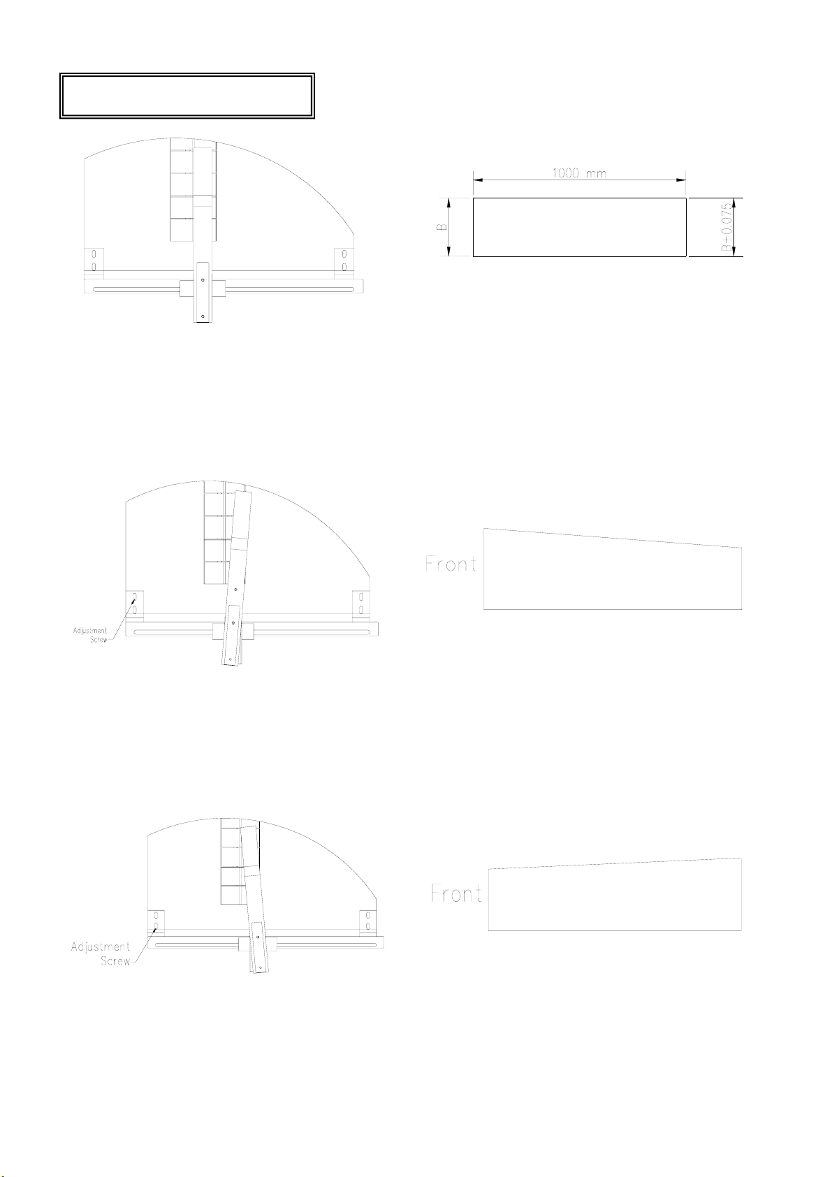
Cutting alignment
Correct alignment:
Cutting line must be parallel to fence.
Cut Result
If the cutting line is parallel, the width
difference after cut between the front
and rear end is ±0.075 mm tolerance
is acceptable.
Cut Result
Improper alignment:
Fence is not parallel; it moves to the right side.
Cut Result
Improper alignment:
Fence is not parallel; it moves to the left side.
10
Page 11

Replacin
g
1. Disconnect the machine from the power source;
verify that the machine has come to a full stop.
2. Loosen the saw arbor lock lever (1), open the cover
of the pressure mechanism; raise the saw arbor by
turning hand wheel (2) until the teeth are 5-10mm
higher than the caterpillar.
3. Insert the saw arbor wrench into the spindle shaft (3);
rotate the saw blade clamp screw with the T-wrench
(4).
4. Remove the saw blade flange and screw; these
procedures will allow the loading or unloading of the
saw blade.
5. Clean the inner sides of machine, the saw blade and
the washer; before replacing with a new saw blade.
6. Reverse the above procedure after blade has been
properly installed.
7. Remove T-wrench and saw arbor wrench.
8. The saw blade teeth should be 0.5-1.5mm lower than
the caterpillar.
9. Always keep the saw blade sharp in order to reduce
the cutting load and ensure the service life of the
machine.
saw blade
Figure 1
SHAPES AND FEEDINGS OF WOOD
1. The proper method for feeding curved wood is
illustrated in Fig.2 when curved wood is fed with its
curve upwards refer to Fig.3 the pressure rollers on
both sides of the saw will block and the marginal part
of wood will most commonly pop out.
2. If curved wood needs to be cut along the curve; it
must be placed with its curve upwards as illustrated
in Fig.4 if positioned otherwise to be fed; the pressure
rollers will not function smoothly and precision of the
object will not result in satisfactory work. Fig.5
illustrates an improper method of feeding.
3. If the outer covering of wood is to be processed,
(Fig.6) it must be fed into the machine with the
covering facing up. Unsatisfactory results will be
achieved if the outer covering is under pressure from
the rollers. (Fig.7)
Figure 2
Figure 3
Figure 4 Figure 5 Figure 6 Figure 7
11
Page 12

Machine and lubrication
Lubricator should be verifed daily before starting work operations; this will
ensure normal functions at all times. A lubrication failure may cause serious
damage to the machine, if the lubricator is damaged; stop machine operations
immediately in order to prevent damage to the caterpillar.
The lubricator of this machine has been designed with a safety device in
order to ensure a longer service life. When the oil is under the minimum
requirement amount it will shut o the machine immediately, ll up the lubricator
in order to re-start your machine
♦ Interior of oil box must be kept clean at all times.
♦ The track of caterpillar’s chain, must be lubricated at all times this is an
important factor for ensuring the accuracy of the machine.
Never over-ll the oil tank, never use recycled oil.
♦
Oil must be relled after 100 hours of operations, and changed after 200
♦
hours of operation. Insucient oil may cause serious noise and fast
wear of gears; excessive oil into the gear reducer may cause oil
leakage.
♦
Rell the oil in the gear reducer until the level reaches over half of its
full capacity.
♦ Properly clean and dust your machine each time work operations are
completed.
Contents list
♦ 1-pc Tool Box
♦ 1-pc Oil Pot
♦ 1-pc T-Wrench #19
♦ 1-set Open-Ended Wrench
♦ 1-set Hex Wrench Set
♦ 4-pc Screw M16 x 80
♦ 4-pc Nut M16
♦ 4-pc Steel Pad
♦ 1-pc Open Wrench #45
Page 13
192311
5
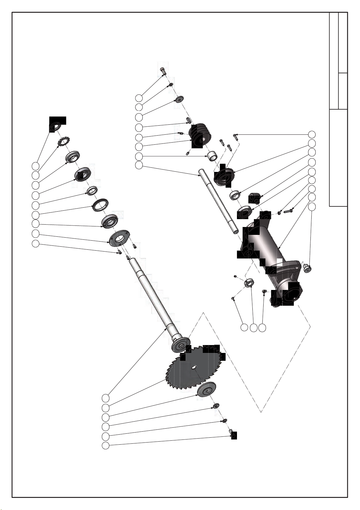
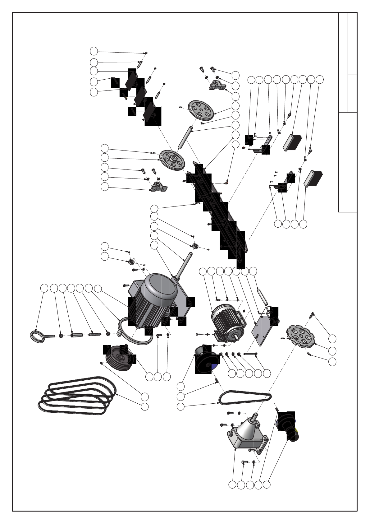
Arbor Spindle Assembly
14
19 15
2 17 13 31 32 13
2221
24
20 18 3
29
8 12
7
26 16
30
6 10 28 27 33
4
34
25
Page 14

1
1
1
1recpS3103-SR12
1
1
1
1
1gniR
1
1
1
1
QUANTITY
Arbor Spindle Assembly
DESCRIPTION
PARTS LIST
Shaft
Set Collar
Special Nut
Flat Washer
Pulley, Spindle
Special Washer
Press Plate
Special Nut
Main Spindle
Saw Blade, 12"-48T-4W
Grease Nipples, 1/8"-90
23 RS-3015
22 RS-3014
24 RS-3016
25 RS-3018
27 RS-3020
NO. PART NO.
103-01M ,wercS paC5011201041
361-6M ,wercS paC3501201042
303-6M ,wercS paC7501201043
26 RS-3019
261-8M ,wercS teS250270104
1
2
29 RS-3041
28 RS-3021
1
1
1
32 RS-3059 Ring133 413012108
31 RS-3058
30 RS-3051
1
1
34 410030003
1
1
2
1
1
1
1
1
1tnorF ,reppotS
PARTS LIST
Ball Bearing, 6207-2NK
Set Screw, M8-10
Hex Head Bolt, M12-35
Hex Head Bolt, M8-35
Lock Washer, 12mm
Lock Washer, 10mm
Parallel Key, 10-8-36
Ext Tooth Washer, AW08
Spanner Lock Nut, AN08
Ball Bearing, 7208
Spindle Shaft Box
Cover, Spindle
401160003
12 403017137
13 403020001
401120003
15
14
RS-3003
16
RS-3008 Cover, Front
17
20 RS-3012 Stopper, Rear
18 RS-3009
19 RS-3011
401230022
5
NO. PART NO. DESCRIPTION QUANTITY
4 401072049
7 401010022
6 401010053
8 401101005 Hex Nut, M8
9 401150005
10 401150006
11
Page 15

2
3
13
392640
9
37
41
36
12
40
35
38
9
16
33
19
17
11
43
45
144847
44
Infeed Body Assembly
13
50
42 6
5
21
49146
14
17 10
2
7
15
18
34
28
25
14
4
31 13 13
8
29
23
24
20
27
22
9
163032
Page 16

2
1
1
1
2
1revoC6503-SR24
2
1taeS
1
1
36
1
1
1
1
Infeed Body Assembly
PARTS LIST
Special Ring
Bushing
Special Ring
Special Pin
Spacer
RS-3048
Anti-Kickback Finger
Block
Block
Shaft
RS-7012-4
RS-7013-JET-GR
RS-7015-JET
Adjustable Hand Levers, M12-30
Bracket
Shaft
NO. PART NO. DESCRIPTION QUANTITY
38 RS-3044
1
39 RS-3045
1
40 RS-3046
1
41
4
36 RS-3042 Cover
37 RS-3043
1
2
44
45
43 RS-7011-GR3
4
4
46 RS-7014-JET-GR
252-8M ,wercS paC97022010401
4
7
49 RS-7038-GR
47
48 RS-7016-JET
50 402040005
152-5 ,niP gnirpS20000210452
4
5
661-8M ,wercS teS25017010431
26-6M ,wercS teS33017010421
4
6
5
3
4
1
1
1
223-5 ,niP gnirpS30000210462
1
1
1
1
1
1
1
1
QUANTITY
DESCRIPTION
PARTS LIST
Lock Washer, 8mm
Lock Washer, 6mm
Gear Lever Handles, 1162-M10-125
Wandwheel, D200-20
Set Screw, 3/8-16-3/8
Wandwheel, D200-25
Phillips Head Screw, M5-12
Lifting Eye Bolt, M12
Lock Washer, 12mm
Washer, 12*24
Special Taper Pin, 10-45
Washer, 8*17
Parallel Key, 7-7-18
Eat Tooth Washer, AW04
Spanner Lock Nut, AN04
Thrust Bearing, 51104
Bevel Gear, 30T
Bevel Gear, 14T
Locking Stopper
Shaft
Lead Screw
Lock Seat
Lead Screw
401150006
15
16 401150003
401150004
17
18 401140022
19 401140013
20 401230004
21 401220002
22 403060001
23 401120001
24 401160001
27 RH-2020
RH-2024
28
29 RS-1001 Cover, Gear Box130 RS-1002 Gear Box131
RS-1005
32 RS-1006
33 RS-1008
34 RS-3001-2
35 RS-3040
402010002
1
NO. PART NO.
2 401072133
3 402050002
402050004
4
401271004
5
6 401042004
401021132 Cap Screw, M12-55
7
8 401021030 Cap Screw, M5-16
401022082 Cap Screw, M8-40
9 401022057 Cap Screw, M6-30
11
401071035 Set Screw, M6-10
14
Page 17

371078
34 46
77
48
12
58
43
59
77
16
20
39
27
62
83
25
57
12 76
45
Roll & Frame Assembly
34
10 47
75
25
14
10
84
56
10
48
36
1
15
17
4
54
74
46
13
34
67
44
50
34
47
52
84
56
44
25
15
17
40
19
23
66
38 72 60 71 3213033
2
29 32
8
24
7 28 73 7 28 31 22 61 26 18
64
8
65
29
41
11
42
48
49
52
10
55
36
41
42
55
36
36
1
53
4
1
36
4
54
74
13
36
55
10
51
44
49
53
4
56
84
1
36
36
55
51
50
70 63
5
3582
10
56
84
79356 8180
47
34
67
46
9
68
69
34
44
Page 18

2
3
3
2thgiR ,mrA1102-SR
3
2
2
4
4
2
2
29
1
1
1
1
1
1
1
1
1
1
2
1
1
1revoC7305-SR37
1
2
1
1
1
1
2
1
2
1
2
4
Roll & Frame Assembly
PARTS LIST
Bearing Cover, Right
Bearing Cover, Left
Shaft
Arm, Left
Shaft
Bearing Cover, Left
Bearing Cover, Right
Roller, Left
Shaft
Roller, Right
Anti-Kickback Finger
Shaft
Shaft
Slide Plate
Lock Bar
Chip Funnel
Lock Bar
Back Safety Guard
Knob Screw, M10-20
Knob
Hinge (Big)
Roller
Shaft
Hinge (Small)
Needle
Roller Seat
Roller
Block
Bracket
Bracket, 100mm
Shaft
Wobble Arm
Side Guard
Adjustable Hand Lever, M12-45
Grease Nipples, M6
PART NO. DESCRIPTION QUANTITY
RS-5034
71
69 RS-2096-GR
70 RS-2097-GR
318M ,tuN xeH50010110452
6
36M ,tuN xeH40010110442
RS-6021-JET
RS-6025-JET
RS-7003-JET
RS-8052 Bushing
74
75
77
72 RS-5036
2
4
2
5
78 RS-7037-8
76 RS-6026-GR
2
2
2
81 RS-8054
79
80 RS-8053
82 RS-8055 Bushing283 402040004
84 410030001
2taeS gnirpS2002-SR
1mm55 ,gnirpS eriW
8
6
4
1
1
1
2mm551 ,gnirpS eriW3002-SR24
1
4
1
NO.
RS-2016
RS-2017
RS-2008
47
48 RS-2009
46 RS-2007
4
2
1
RS-2012
49 RS-2010
50
51
261-6M ,wercS daeH nottuB230230104
4
2
RS-2015
52 RS-2013
53 RS-2014
54
302-6M ,wercS paC5502201048
202-8M ,wercS paC8702201049
4
55
17
RS-2022_1
56
57
58 RS-2023-GR
59 RS-2025
202-8M ,wercS teS450270104
4
16-6M ,wercS teS
4
62 RS-2031
60 RS-2029
4
63 RS-2034-GR
61 RS-2030
303-8M ,wercS teS65027010461
4
6
66 RS-2083-1
64 RS-2039
65 RS-2040
67 RS-2094-JET
68 RS-2095-GR
2
2
2
201M ,tuN xeH60010110432
2
QUANTITY
PARTS LIST
Hex Head Bolt, M12-40
Hex Head Bolt, M10-35
Washer, 6.5*25
Phillips Head Screw, M6-12
Phillips Head Screw, M4-30
Phillips Head Screw, M5-12
Button Head Screw, M6-25
Hex Head Bolt, M10-80
Hex Head Bolt, M8-20
Hex Nut, M4
Lock Washer, 12mm
Lock Washer, 5mm
Lock Washer, 10mm
Lock Washer, 8mm
Lock Washer, 6mm
Washer, 8*17
Washer, 6*13
Washer, 4*9
Ball Bearing, 6302-2NSE
Spring Pins, 6-28
Ball Bearing, 6204-2NSE
Ball Bearing, 696-ZZ
Limit Switch TZ7311
Bracket
Roller
401072057 Set Screw, M8-35
10 401071035 Set Screw, M6-10
401071033
12 401071049 Set Screw, M8-10
11
6.5-25-2.0
1
NO. PART NO. DESCRIPTION
401042010
4
2 401042002
3 401042004
401021028 Cap Screw, M5-12
5
6 401032034
7
13 401071052 Set Screw, M8-16
401072055 Set Screw, M8-25
17
15
14
20 401010054
18 401010038
19 401010043
22 401101002
21 401010019
27 401150006
28 401150002
26 401150005
30 401150004
29 401150003
33 401140004
32 401140010
31 401140001
36 403015162
34 403015134
37 401200019
35 403070001
RS-2001-GR2 Roller Seat
38 416040001
39 RS-1007
41
40
RS-2006-GR
RS-2004 Wire Spring, 135mm
43 RS-2003-JO
45
44
Page 19
13
34
41
63
3
65
21
61
4
5
64
60
82
21
45
24
2
46
56
10
46
2
10
55
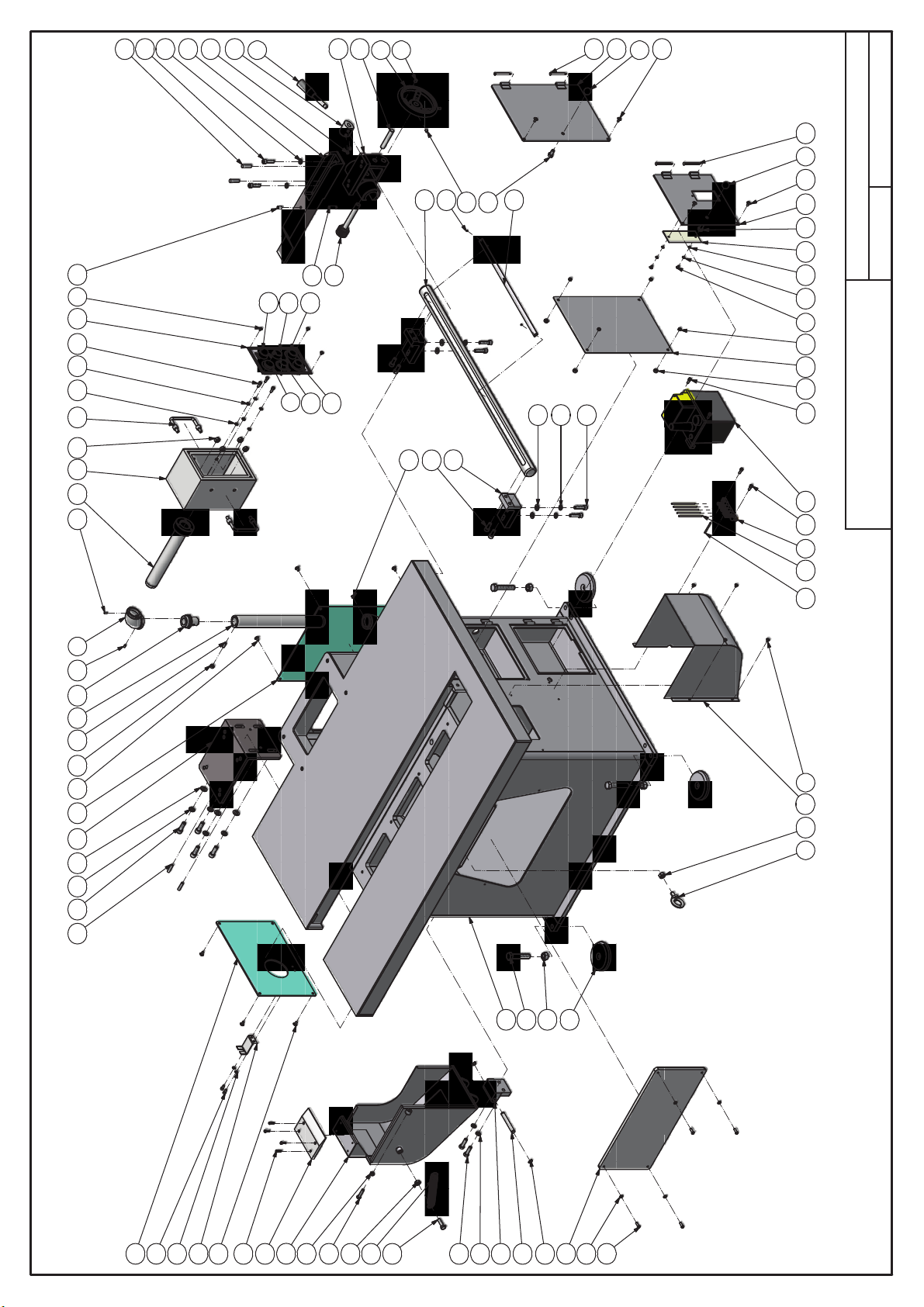
Table & Stand Assembly
19
9
44
18
40 36
79
29
74
1 20 76
20
77 75
83
50
62
80
80
8
81
81
59
20
12
37
34
14
39 73 2418
39
32 9
33 54
78
18
6
47 48
10 33 23
52 53
35 38
42 15
31
49
26
58
9
66
30
7
17
71
36
57
10
70
27
28
16
33
67
51
25
25
34
68
72
69
43
11
40
Variable Speed + safe protecting cover
Page 20

1
5
4
QUANTITY
DESCRIPTION
PARTS LIST
Shaft, Hinge
Oil Tube, 4x2.5-270
Oil Tube, 4x2.5-700
1
4
1raeG
1
1
Plank, Electrical Box
Bracket
1
1revoCD_2-1004-SR
1
1
2
Stand
Bracket
1
1ecneF
1xoB raeG3RG-9104-SR16
Special Screw
Column Gear
1
1
1
Shaft
1
Setting Block
Cover Plate
1
1
Shaft
Backet
1revoC2305-SR07
1
1
1
1
1
1
1
Switch Box
Bracket
Acrylic Piece
Arm, Control Box
2
1
Arm, Control Box
Lubricator, SMA-602-5FB
"U" Collapsidle Handle, A-42-A-3/8"
25-3# ,teviR20008210428
2NO ,nottuB21001061418
2FFO ,nottuB31001061408
1
Table & Stand Assembly
Electric Power Button
Variable Speed + safe protecting cover
410050005
46 KT02
47
NO. PART NO.
QUANTITY
DESCRIPTION
PARTS LIST
48 410050010
1
1
2
Elbow, 1-1/4PT
Gear Lever Handles, 7108-M12-138
Ball Knobs 1110-25-M10
RS-2100 Tension Spring, 150
50 RS-1033-GR
49 RH-1015 Cast Iron Feet
51
1
1
1
Contactor, Lubrication DB-7
Set Screw, 3/8-16-3/8
Wandwheel, D150
52 RS-3047
1
Lifting Eye Bolt, M12
RS-4001-2_C
53 RS-4001-2_A Cover154
1
10
Phillips Head Screw, M5-8
55
12
Phillips Head Screw, M6-12
RS-4001-2_F Cover
56 RS-4001-2_E Cover157
4
4
Button Head Screw, M6-20
RS-7030-JET
RS-7031-JET-GR Rotation Seat
RS-7032-JET
75
1
76
461M ,tuN xeH
RS-7033-JO
77
4
78 417010001
79 402020004
8
4
68M ,tuN xeH50010110433
Lock Washer, 10mm
Lock Washer, 12mm
83 416010014
253-7 ,sniP repaT10002210424
204-01 ,sniP repaT200022104
5
Lock Washer, 6mm
4
4
4
7
Washer, 5*10
Washer, 10*21
Washer, 12*24
Washer, 6*13
1
1
2
Scale, 480mm
Panel
Retaining Rings For Shaft, S12
RS-5035
58 RS-4001-JO
59 RS-4016
4
253-01M ,wercS paC60112010431
62 RS-4025
60 RS-4017
4
63 RS-4028-GR1
7
221-6M ,wercS paC150220104
461-5M ,wercS paC03022010461
66 RS-5009 Cover
64 RS-4031-GR
65 RS-4032-GR
4
161-01M ,wercS teS56017010491
301-6M ,wercS teS53027010402
69 RS-5019
67 RS-5017
68 RS-5018
2
1
2
Hex Head Both, M10-20
Set Screw, M8-16
72 RS-6008 Cover
71
3
4
Hex Head Both, M16-80
74
73 RS-6013
1
4
101M ,tuN xeH600101104
Hex Head Both, M8-35
K-036
43 401252007
K-026
45
44
402050001
5
6 417020001
401271004
7
401032033
8 416010011 Emergercy Stop
9 401042008
11
10 401042101
12 401021104 Cap Screw, M10-25
401072133
1 410020002
3 402010009
2 402060001
NO. PART NO.
4
401021107 Cap Screw, M10-40
14
401021128 Cap Screw, M12-35
15
18 401021053 Cap Screw, M6-16
17
22 401072052
21 401072049 Set Screw, M8-10
401010038 Hex Head Both, M10-35
24 401010035
23 401072054 Set Screw, M8-20
27 401010022
28
25
26 401010070
29 401101013 Hex Nut, M10 x 1.25
32 401101004 Hex Nut, M6
31 401101012
30 401101007 Hex Nut, M12
34 401150005
35 401150006
36 401150003
37 401140005
38 401140014
39 401140023
40 401140003
41
Page 21

4
3
13
37
30
59
20
57
5
58
55
74
54
20
40
23
2
50
41
10
2 41
10
49
23
Table & Stand Assembly
18
75
67 19 1 19 68 66 7125 36 32 17 39 9
69
45
56
72
72
8
73
73
19
53
12
33
14
30
35 65
35
17
42 43 6 17 70 29 48 28 9
9
60
26
7
38 15 31 34 46 47 10 29 22
27
24
52
44
16
63
32
10
51
16
9
62
61
11
64
36
Variable Speed + standard protecting cover
Page 22

1
1
1revoC
QUANTITY
DESCRIPTION
PARTS LIST
Bracket
Plank, Electrical Box
1
1revoC
1revoCD_2-1004-SR94
1
2
1
Bracket
Stand
1
1ecneF
1xoB raeG3RG-9104-SR
Column Gear
1
Special Screw
Shaft
1revoC1305-SR16
1
1
Setting Block
1
1
Bracket
Bracket
1
1revoC
1
Switch Box
Acrylic Piece
1
1
1taeS noitatoRRG-TEJ-1307-SR76
Arm, Control Box
2
1
Arm, Control Box
Lubricator, SMA-602-5FB
"U" Collapsidle Handle, A-42-A-3/8"
25-3# ,teviR200082104
2NO ,nottuB21001061437
2FFO ,nottuB31001061427
1
Table & Stand Assembly
Electric Power Button
Variable Speed + standard protecting cover
RS-4001-2_A
46 RS-3047
47
NO. PART NO.
QUANTITY
DESCRIPTION
PARTS LIST
48 RS-4001-2_C
1
1
2
Elbow, 1-1/4PT
Gear Lever Handles, 7108-M12-138
Ball Knobs 1110-25-M10
RS-4001-2_F Cover
50 RS-4001-2_E
51
1
1
1
Contactor, Lubrication DB-7
Set Screw, 3/8-16-3/8
Wandwheel, D150
RS-4017
53 RS-4016
54
52 RS-4001-JE
1
1
13
Lifting Eye Bolt, M12
Phillips Head Screw, M5-8
55
12
Phillips Head Screw, M6-12
RS-4028-GR1
56 RS-4025
57
58 RS-4031-GR
59 RS-4032-GR
60 RS-5009 Cover
4
4
Button Head Screw, M6-20
4
4
253-01M ,wercS paC60112010431
421-6M ,wercS paC25012010461
RS-6008
64
301-6M ,wercS teS53027010491
66 RS-7030-JET
65 RS-6013
4
68 RS-7032-JET
2
261-8M ,wercS teS25027010412
1
Set Screw, M8-20
Hex Head Both, M10-20
62 RS-5033
63 RS-5035
7
1
402020004
69 RS-7033-JO
70 417010001
71
1
452.1 x 01M ,tuN xeH31010110452
4
Hex Head Both, M16-80
416010014
74
75
204-01 ,sniP repaT20002210473
5
5
4
6
46M ,tuN xeH400101104
Lock Washer, 12mm
Lock Washer, 10mm
4
4
4
Lock Washer, 6mm
Washer, 12*24
Washer, 10*21
Washer, 5*10
253-7 ,sniP repaT10002210483
7
Washer, 6*13
4
1
1
Shaft, Hinge
Scale, 480mm
Panel
4
1
5
1raeGRG-3301-SR
Oil Tube, 4x2.5-270
Oil Tube, 4x2.5-700
42 410050005
43 410050010
RH-1015 Cast Iron Feet
45
44
402050001
5
6 417020001
401271004
7
401032033
8 416010011 Emergercy Stop
9 401042008
11
10 401042101
12 401021104 Cap Screw, M10-25
401072133
1 410020002
3 402010009
2 402060001
NO. PART NO.
4
401021107 Cap Screw, M10-40
14
401021128 Cap Screw, M12-35
15
18 401071065 Set Screw, M10-16
17
20 401072049 Set Screw, M8-10
22 401072054
23 401010035
24 401010070
27 401101012 Hex Nut, M16428
26 401101007 Hex Nut, M12
29 401101005 Hex Nut, M8
30 401150005
31 401150006
32 401150003
33 401140005
34 401140014
35 401140023
36 401140003
401021053 Cap Screw, M6-16
KT02
39 K-026
41
40 K-036
Page 23
29
44
43
45
29
11152152
51
9
32 10
38
10
32
41
15
52 21
51
11
47
42
1
7
1
50
23
20
12
46
12
20
Motor & Drive Unit Assembly
7
49
23
46
4
36
30
33
35
2
19
34
20
26
13
31
11
5
27
3
25
40
17
22
18
39
11
11 48 26
24
18
24
14
8
16
6
21
28
(10+2)HP / (15+2)HP + Variable Speed
Page 24

1
1
1
1
PARTS LIST
Special Bolt, M16-110
Pulley
Shaft
Shaft
1
1
1
38
38
Rail Body
Caterpillar Block
Shaft
1
1
2
38
Brush
Bakelite
1ecarB
Shaft
Sprocket 10T
2
2
1ecarB
Motor & Drive Unit Assembly
Ball Bearing Assembly, UCP205
Idle Wheel
RS-3053 Motor Seat, 10HP
36 RS-3026
37 RS-3028
NO. PART NO. DESCRIPTION QUANTITY
QUANTITY
DESCRIPTION
PARTS LIST
38 RS-3032-JET
1
5
1
Motor, 10HP/15HP
Handy Couplings, 1/8"-4mm
Cog Tooth Belt, 1220VB30-22
41
39 RS-3036
40 RS-3052 Motor Seat, 2HP
4
1
1
V-Bell, A-55
Reducer Pulley, AH2-24
RS-4007
42 RS-4005
43 RS-4006-C
44
852-8M ,wercS paC9702201049
8
1
Phillips Head Sheet Metal Screw, #8-3/4"
Reducer Worm Gear, B-80-1/50
RS-5013
RS-4030-A
46 RS-5007
47
45
48 RS-5022
0161-8M ,wercS teS250270104
2
4
Hex Head Bolt, M10-25
Hex Head Bolt, M10-35
51 RS-5030
50 RS-5029
49 RS-5028
1
Hex Head Bolt, M12-110
52 403100001
6
161M ,tuN xeH21010110491
4
Hex Head Bolt, M12-35
221M ,tuN xeH70010110481
4
4
Hex Head Bolt, M12-40
Hex Head Bolt, M8-25
8
4
2
2
4
Lock Washer, 10mm
Lock Washer, 8mm
Washer, 10*21
Washer, 12*24
Lock Washer, 12mm
Washer, 8*17
1
2
1
Parallel Key, 10-8-56
Parallel Key, 8-7-32
Parallel Key, 7-7-40
1
1
76
Reducer Pulley, PH2-22
Retaining Rings For Shaft, S12
Hex Nut, M16-Left
1
2
Set Collar
1
1
Adjusting Ring
Spec Eye-Bolt
Special Nut, M16-LH/RH
PART NO.
401010053
12 401010036
13 401010039
401011008
14
410010008
1
NO.
90L4P Motor, 2HP
2 132M4P
4
3 405020003
405010002
5
6 405120203
401060001
7
8 406060125
10 401072051 Set Screw, M8-10411
15
16 401010054
401010020
17
20 401150005
21 401150006
22 401150004
23 401140005
24 401140014
25 401140004
26 401230027
27 401230015
401230005
28
29 401252007
30 M 16 - LEFT
31 405120207
32 RS-3018
34 RS-3023
33 RS-3022
35 RS-3024
(10+2)HP / (15+2)HP + Variable Speed
Page 25

OIL
LEVEL
CONTROL
16
R1
OIL
LEVEL
CONTROL
M2
6
SB4
4
12
2
B
S
SB3
M1
5
SB5
T1
7
10
S1
8
D1
PU
2M1M
18
2
L
O
HL2
11
9
S1 D1
T1
OL1
15
R1
17
HL1
PUMP
MAIN
MAIN
FEED
FEEDING
LIGHT
LIGHT
7 2 7
POWER
1
Q
S
3-1
1
B
S
3
U
A
F
3
1
R1
T1
2
HL0
LIGHT
6
11
5
16 12
4
3-1
3
2
Poewr supply: 220V 60HZ 【380V 50HZ】
R1,T1=LASER
*
R1
220V
TC
120VA
220V
【380V】
0.5mm²
R1 T1
T1
0V
0V
1.25mm²
M2
OL2
1.25mm²
W2V2U2
M
3~
M2
PE
ROTOM DEEFROTOM NIAM
1.5KW 2HP
2W2U
V2
U2
8 945 6
1 2 3
7
W2
8 9
V2
5 6
1 2 3
4
7
【220V60HZ】【380V50HZ】
5.5mm²
【3.5mm²】
M1 D1 S1
OL1
5.5mm²
【3.5mm²】
W1V1 1Y1U X1Z1
M
3~
M1
W1
V1
U1
11.25KW 15HP
Y1
Y1X1Z1
U1 V1 W1
Z1 X1
PE
R
S
T
PE
Limit of Equipment
Page 26

2072 Alton Parkway Irvine, CA 92606 U.S.A.
For Customer Service: +1 (949) 474-1200 or email customerservice@lagunatools.com
Laguna Tools is not responsible for errors or omissions. Specifications subject to change. Machines may be shown with optional accessories.
© 2018, Laguna Tools, Inc. LAGUNA® and the LAGUNA Logo® are the registered trademarks of Laguna Tools, Inc. All rights reserved.
825 Bistline Drive, West Columbia, SC 29172 U.S.A
 Loading...