

laguna 16HD, 16HD classic, Resaw Master, LT18, LT32 User Manual
...
LAGUNA BANDSAWS
16HD-37 MANUAL
LAGUNA TOOLS
2072 Alton Parkway
Irvine, California 92606
Ph: 800.234.1976
www.lagunatools.com
© 2017, Laguna Tools, Inc. LAGUNA® and the LAGUNA Logo® are the registered trademarks of Laguna Tools, Inc. All rights reserved.


3
Chapter 1.Safety rules and warranty Pg. 4-5
Chapter 2.Getting to know your bandsaw Pg. 6-13
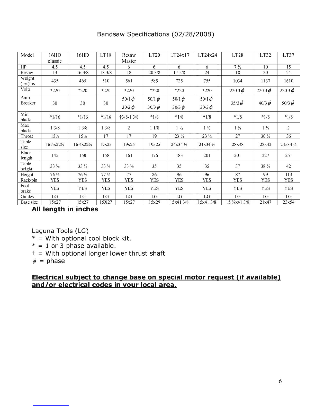
Specification Pg. 6
Noise emission Pg. 7
Receiving your machine Pg. 7
Introduction to bandsaws Pg. 8
What you will receive with your machine Pg. 9
Parts of the bandsaw Pg. 10-13
Where to locate your bandsaw Pg. 13
Chapter 3. Assembling your bandsaw Pg. 14-36
Unpacking your machine Pg. 14-15
Assembling your bandsaw Pg. 16-22
Adjusting the bandsaw Pg. 23-36
Chapter 4. Using your bandsaw Pg. 37-40
Chapter 5. Blades Pg. 41-39
Introduction Pg. 41
Blade terms Pg. 41-36
Blade selection Pg. 36-48
Chapter 6. Maintenance and troubleshooting Pg. 49-56
Chapter 7. Accessories Pg. 57
Chapter 8. Electrical drawings Pg. 58-62
Chapter 9. Spare parts and exploded view drawings Pg. 63-64

4
Read First!!!
Safety Rules
As with all machinery there are certain hazards involved with the operation and
use. Using each one with caution will considerably lessen the possibility of
personal injury. However, if normal safety precautions are overlooked or
ignored, personal injury to the operator may result. If you have any questions
relative to the installation and operation, do not use the equipment until you
have familiarized yourself with the machine.
Read carefully before operating the band saw
1. Keep the working area clean and be sure adequate lighting is available.
2. Do not wear loose clothing, gloves, bracelets, necklaces or ornaments.
Wear face, eye, respiratory and body protection devices as indicated for
the opera tion or environment.
3. Be sure that the power is disconnected from the machine before making
adjustments or fitting and removing an attachment.
4. Never leave the machine with the power on.
5. Do not use dull, gummy or cracked blades.
6. Be sure that the keys and adjusting wrenches have been removed and all
the nuts and bolts are secured.

Limited Warranty
New machines and accessories sold by Laguna Tools carry a one-year warranty
effective from the date of shipping. Machines sold through dealers must be registered
with Laguna Tools within 30 days of purchase to be covered by this warranty. Laguna
Tools guarantees all new machines and accessories sold to be free of manufacturers’
defective workmanship, parts and materials. We will repair or replace, without charge,
any parts determined by Laguna Tools, Inc. to be a manufacturer’s defect. We require
that the defective item/part be returned to Laguna Tools with the complaint. Any
machines returned to Laguna Tools must be returned with packaging in the same
manner in which it was received. If a part or blade is being returned it must have
adequate packaging to ensure no damage is received during shipping. In the event the
item/part is determined to be damaged due to lack of maintenance, cleaning or
misuse/abuse, the customer will be responsible for the cost to replace the item/part,
plus all related shipping charges. This limited warranty does not apply to natural
disasters, acts of terrorism, normal wear and tear, product failure due to lack of
maintenance or cleaning, damage caused by accident, neglect, lack of or inadequate
dust collection, misuse/abuse or damage caused where repair or alterations have been
made or attempted by others.
Laguna Tools, Inc. is not responsible for additional tools or modifications sold or
performed (other than from/by Laguna Tools, Inc.) on any Laguna Tools, Inc.
machine. Warranty maybe voided upon the addition of such described tools and/or
modifications, determined on a case-by-case basis.
Software purchased through Laguna Tools Inc. is not covered under this warranty
and all technical support must be managed through the software provider. Software is
non-refundable.
Normal user alignment, adjustment, tuning and machine settings are not covered by
this warranty. It is the responsibility of the user to understand basic machinery
operation, settings and procedures and to properly maintain the equipment in
accordance with the standards provided by the manufacturer.
Parts, under warranty, are shipped at Laguna Tools, Inc.’s cost either by common
carrier, FEDEX ground service or a similar method. Technical support to install
replacement parts is primarily provided by phone, fax, e-mail or Laguna Tools
Customer Support Website. The labor required to install replacement parts is the
responsibility of the user.
Laguna Tools is not responsible for damage or loss caused by a freight company or
other circumstances not in our control. All claims for loss or damaged goods must be
notified to Laguna Tools within twenty-four hours of delivery. Please contact our
Customer Service Department for more information.
Only new machines sold to the original owner are covered by this warranty.
For warranty repair information, call 1-800-332-4094.

7
Measuring system
Standard ISO 7960 - annex J ( NFE 64-209 )
Measurements tolerance
< 4 dB
Working, without
aspiration
L Aeq
LW (A)
Lpc
84,7 dB (A)
97,1 dBw (A)
5,1 mW (A) < 130 dB (A)
Noise emission
Notes concerning noise emission: Given that there exists a relationship between
noise level and exposure times, it is not precise enough to determine the need
for supplementary precautions. The factors affecting the true level of exposure
to operators are clearly the amount of time exposed, the characteristics of the
working environment, other sources of dust and noise, etc.: for example,
adjacent machines, in other words the level of ambient noise. It is possible that
exposure level limits will vary from country to country.
Measuring system Standard ISO 7960 - annex J ( NFE 64-209 )
Receiving your machine
Note: It is probable that your machine will be delivered by a third party. Before
you unpack your new bandsaw you will need to first inspect the packing,
invoice and shipping documents supplied by the driver. Insure that there is no
visible damage to the packing or the machine. You need to do this prior to the
driver leaving. All damage must be noted on the delivery documents and signed
by you and the delivery driver. You must then contact the seller [Laguna Tools]
as soon as practical. If damage is found after delivery, contact the seller as
soon as practical.

8
Introduction to bandsaws
This bandsaw is designed to give you years of safe service. Read this owner’s
manual in its entirety before assembly or use.
The bandsaw is generally defined as a saw blade in the form of an endless steel
band that rotates around two or more wheels. This blade is a continuous metal
band with teeth on one side. As the wheels rotate, so does the band, which
creates the continuous sawing action. Because the direction of the blade is
always downward toward the table, there is little danger [except for special
cuts] that the wood will be thrown back at the operator, which is called a
kickback. There is always danger of kickback when a circular saw is being used.
For safety reasons many woodworkers prefer the bandsaw especially when
cutting small pieces. The unique feature of the bandsaw is that the work piece
can be rotated around the blade creating a curve. It is the tool most often used
when curves have to be cut in wood. Because the bandsaw blade is fairly thin,
it can cut thick stock with a minimum of horsepower. For this reason the
bandsaw is often used when valuable pieces of wood are made into a thin piece
of veneer.

9
Tool Kit
Fence, table insert, and door guard
Table
What you will receive with the bandsaw.

10
Parts of the bandsaw
The bandsaw does not have many parts. The major parts are discussed in this
manual. If you are not familiar with the bandsaw, take the time to read this
section and become familiar with the machine.
Flywheel
The blade is suspended over two wheels that are covered with rubber called a
tire. The tire cushions the blade and protects the teeth from coming in contact
with the metal of the flywheel. The lower wheel is the drive wheel and is
attached to the motor with a rubber drive belt. The lower flywheel powers the
blade and pulls the blade down through the work piece. The top wheel has two
functions. One function is to balance or track the blade on the wheels, and the
second one is to tension the blade. Both functions are adjustable.

11
Body
The body of the bandsaw is a "U"-shaped frame, which houses all the parts of
the machine. This is the heart of the bandsaw and has to be very rigid as it
takes the strain of the blade being tensioned.
Table
The table supports the workpiece and can tilt to produce cuts at various angles.
It has a groove to the right-hand side of the blade which is used to guide the
miter gauge. In the center there is a plastic table insert which the blade passes
through. Should the blade wander off center, this table insert will protect the
blade from damage as it is soft and will not damage the blade. The table also
supports the adjustable fence, which is used for parallel cuts. There is an
aligning pin, which joins both sides of the table and stops the table from
warping [attached by a wire]. The pin must always be fitted in the table and
only removed when removing or fitting a blade.
Blade guides
There are two sets of blade guides, one above and one below the table. The
function of the guides is to give the blade stability and ensure that the blade
movement left / right, forward / back is kept to a minimum. The guides above
the table are fitted to a shaft that has vertical adjustment. The upper guides
are adjustable so that the guides are held just above the job being cut. This
gives the blade the maximum amount of stability and also keeps the amount of
blade that is exposed to a minimum. If you are using blades narrower than ¼",
you will need to purchase a cool block guide system.
Guards
When running, the blade can be very dangerous and the amount of blade that
is exposed must be kept to a minimum. The machine is supplied with a number
of guards all of which MUST be installed and used while the machine is running.
There is a guard that is attached to the lower door and is adjustable vertically
once the door is closed. There is a hinged guard on the guide vertical
adjustment shaft. The guard is only opened to install or remove the blade.
There is a clear plastic guard on the upper blade guide. This guard must be
adjusted just above the wood being cut.
Drive
The drive [power] is supplied to the machine by an electric motor located at the
back of the machine. It powers the lower flywheel through a rubber drive belt
and is controlled by switches that are mounted on the frame vertical post at the
front of the machine. It is also controlled by switches on the upper door and the

12
foot brake.
Electrical connection
This is achieved by connecting the electrical supply to a terminal box located at
the back of the machine. Never connect directly to the electrical motor, and all
electrical connections must be conducted by a qualified electrician. For detailed
instructions see the assembly section of the manual.
Brake
The machine is supplied with a foot brake. It is located close to the ground on
the righthand side of the machine. It has two functions. First, to remove the
power to the motor, which is achieved with a switch that is mounted on the
body of the machine. The second function is to slow the lower flywheel and this
is achieved by applying a brake pad to the flywheel. The more pressure that is
applied, the faster the flywheel slows.
Dust collection
The bandsaw produces a lot of sawdust, so extraction is very important. This is
achieved by connecting a dust extraction hose to the back of the machine with
a minimum capacity of 1,000 CFM.
Identification
There is a plate at the back of the machine listing all the manufacturing data
including the serial number, model, blade length etc.
Tension scale
Tension scales are designed to indicate the compression of a spring. As a rule,
the greater the spring compression, the greater the tension on the blade. The
tension scale does not register until the blade is relatively taut and is located on
the inside of the body vertical post. The tension scale is a general reference and
not a rule.
Tilt and tension mechanism
The upper wheel is attached to the tilt and tension mechanism. This mechanism
adjusts the wheel so that the bandsaw blade can be adjusted for tracking. This
is achieved by a screwed handle at the back of the machine that pushes on the
mechanism and adjusts the axis of the wheel so that it runs true with the lower
wheel. The second function is to tension the blade, which is achieved by
adjusting the upper flywheel vertically. A handle is located below the wheel

13
and, when rotated, will move the wheel up or down. The mechanism has a
spring, which helps to keep the tension constant as the blade expands and
contracts with the heat generated by the cutting action. The lower flywheel is
also adjustable for tracking and has 4 bolts at the back of the machine that
adjust the wheel shaft. The lower wheel is factory set and should not need
adjustment.
Fence
The fence is located to the left of the blade and is used to assist in parallel cuts.
It is adjustable for the drift of the blade and also the thickness of the cut.
Where to locate your bandsaw
Before you remove your bandsaw from the pallet, select the area where you
will use your machine. There are no hard and fast rules for its location but
below are a few guidelines.
1. There should be an area at the front and back of the machine suitable for
the length of wood that you will be cutting. If you intend to use your saw
for scrollwork, this may not be important but should be considered at this
stage.
2. Adequate lighting. The better the lighting, the more accurate and safely
you will be able to work
3. Solid floor. You should select a solid flat floor, preferably concrete or
something similar.
4. Close to power source and dust collection.

14
Unpacking your machine
To unpack your machine, you will need tin snips, knife and a wrench.
1. Using the tin snips, cut the banding that is securing the machine to the
pallet.
WARNING: EXTREAM CAUTION MUST BE USED BECAUSE THE
BANDING WILL SPRING AND COULD CAUSE INJURY.
2. Lift the box off and discard.
3. Using the knife, cut the plastic wrap from the top. The table, motor, fence
and accessories that were ordered could be attached to the side of the
machine and extreme caution must be taken that the parts do not fall and
cause injury or damage. Remove them in order from the top and set
aside.
4. Place the motor on the pallet behind the machine. Ensure that there is no
tension on the motor wiring. It is
recommended that the motor be assembled to
the bandsaw prior to removing the bandsaw
from the pallet [see mounting motor]. If you
decide to remove the bandsaw prior to
assembling the motor to the bandsaw, ensure
that there is no tension on the motor wiring at
any stage of the operation.
5. Remove the base mounting bolts that secure
the machine to the pallet [shown removed].
6. It is recommended that the machine be
removed from the pallet by lifting it with a
hoist or forklift. There is an eyebolt at the top
of the machine, and this should NEVER be
used to lift the machine. It is used to secure
the machine horizontally during ship ping only and is not designed to take
the load of the machine.
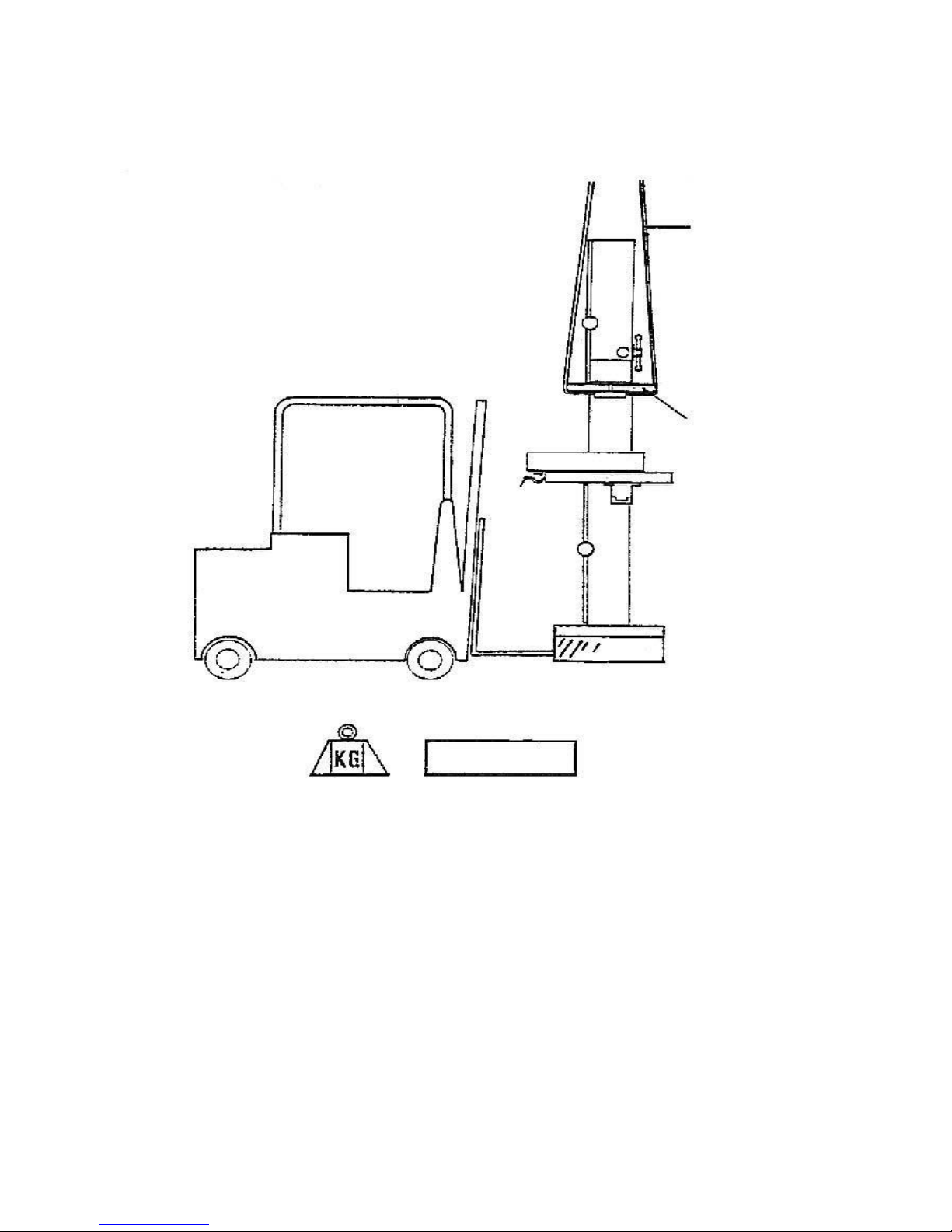
Place a sling through the bandsaw as shown below behind the tension-adjusting
wheel and lift vertically.
Remove the pallet and lower to the floor.
The machine can be lifted using a forklift truck, sliding it onto the forks or by
using a forklift “SLING”, as shown with a lifting capability of 2,000 Kg (440lb).
15
If no lifting device is available, the machine can be removed from the pallet as
follows: Note: The machine is heavy, and if you have any doubt about the
described procedure, seek professional assistance. Do not attempt any
procedure that you feel is unsafe or that you do not have the physical capability
of achieving. With two or more people, move the machine so that the base of
the bandsaw is over the edge of the pallet. Tilt the bandsaw away from the
pallet so that the base of the machine touches the floor, slide the pallet from
under the machine and then move the bandsaw to the vertical position so that
it is completely resting on the floor

16
Belt tensioning bolt
Mounting the motor
Two people are required to assemble the motor to the bandsaw; build up
wooden blocks to the right height to rest the motor on. One person holds the
motor in position, and the other will fit the drive belt
and the bolts.
1. Remove the two mounting nuts on the rear of
the machine. Make sure that there are washers
between the bolts and the inside face of the
machine.
2. Hold the bolts to prevent them pushing through.
3. Using a block to
support the motor,
guide the motor onto
the mounting bolts.
Insure that the drive
belt is on both the
motor pulley and the
fly wheel pulley. The
drive belt can be fitted
later if you prefer, but
it is preferable to
assemble it at this
stage. If you decide to
fit the drive belt after
fitting the motor, you
will have to adjust the
motor to its lowest position and once fitted the
motor back up to the tensioned position.
4. Once the belt is mounted on both the
pulley "V" grooves, apply tension by
adjusting the tensioning bolt, using the
supplied 17 mm wrench. The correct
tension is 3/16" deflection when using
your thumb on one side of the belt. If the
tension is too tight, you will experience
motor strain: if it is too loose you will
experience belt slippage and lack of
power. After a few hours of operation it
is necessary to check that the tension is
correct, as the belts will bed into the "V"
grooves. As a guide, the belt should have
the same tension/deflection as the fan or
alternator belt on your car.

17
Mobility kit
If you have purchased a mobility kit, now is the ideal time to fit it as the table
has not been fitted to the machine and the bandsaw is lighter, but the mobility
kit can be fitted later if you require it.
Mobility kit assembly procedure
1. Rest the bandsaw on a 2" X 4" wood or something similar.
2. Fit the shaft through the base of the bandsaw.
3. Fit the wheels, washers and split pins as shown on both sides of the base.
4. Fit the front bracket as shown. Note the number of holes in the bracket
may vary depending on the bracket supplied.
Note: The mobility kit may be supplied with 2 spacers that are used to
adapt it for other machines. Discard the spacers.
Note: Leveling bolts and a flat head counter sunk screw are provided
with the machine. If you are fitting a mobility kit you will not need the
bolts/screw. Discard them.

18
Installing the Table
The bandsaw is supplied
with a zero stop that is
adjustable and comes
factory set
Insert
Two people are required to mount the table
to the machine.
1. Remove the lock-down bolt, handle and
the pin from the trunnion.
2. Position the table on the
trunnion, taking care not to
damage any of the table or
trunnion surfaces.
3. While one person supports the
table, the other person feeds the bolts and the lock down through the
trunnion slots.
4. The table can be tilted to a maximum of 45 degrees away from the
column. To angle the table, remove the table insert to allow the blade to
pass through the hole. Loosen the lock-down handle, using the supplied
wrench. Crank the trunnion gear so that the table moves to the required
angle and lock in position. To return the table to the zero position,
reverse the procedure.
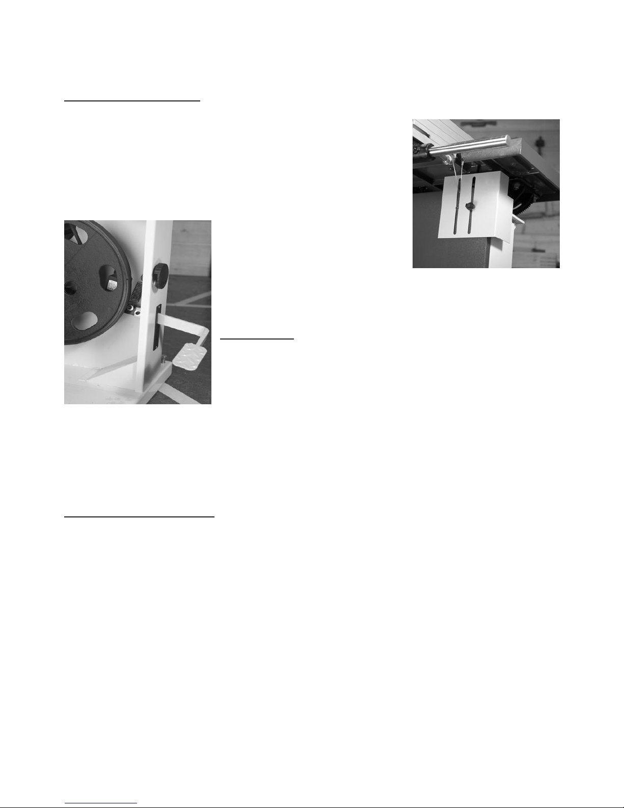
Table insert
The machine is supplied with a removable table
insert. The holes of the insert improve the dust
collection near the blade. Adjusting screws at the
bottom of the table allows the insert to be
adjusted vertically so that the level between the
table and the insert are level. It is recommended
that the insert be replaced when the slot becomes

19
too wide; this will ensure that the job is supported efficiently and safely. When
the insert is replaced, you will have to sand the sides so that the insert fits
correctly in the table hole. You will also have to cut the blade slot to suit your
machine.

20
Fence
The bandsaw is supplied with a cast iron or aluminum fence depending on the
machine that you purchased. Assemble the fence to the cast-iron bracket with
the bolts and steel block provided. Adjustment and squaring of the fence will be
covered later in the manual. Slide the bracket onto the round steel bar
[attached to the table]. The fence is used to the left of the blade, so ensure
that it is on the correct side of the table before locking in position with the
ratchet handle provided. Note: The aluminum fence can be fitted so that it can
be used in high or low position [also covered later in the manual].
Dust collection
The bandsaw must be connected to a dust collection system or machine. As a
general rule the stronger the extraction, the better; but 1,000 cubic feet a
minute is the minimum that should be used. The diameter of the dust collection
port on the bandsaw is 4". Most US standard hoses are 4" in diameter. You can
purchase a step-down adaptor from Laguna Tools or from your local hardware
store in the plumbing or heating department if you
use a smaller hose.
21
Bottom blade guard
It is very important to have the blade covered for
safety. A guard is provided at the top of the lower
door. This guard must be moved vertically and
clamped in position before operating the bandsaw. To
open the door, the guard will have to be lowered.
Should the blade break, this guard protects the
operator from the blade
escaping under the table. To
assemble the guard remove
the thumbscrew that you will
find stored on the inside of
the door.
Align the guard on the bolt and install
the thumbscrew on the outside of the door.
Foot brake
A foot brake is attached to an arm inside the machine
with two bolts. As it is moved down, a switch removes
power to the motor. Continued downward movement
contacts a brake pad that slows the lower flywheel.
Should the blade break the foot brake only slows the lower flywheel and the
upper flywheel may still be rotating, so care must be exercised when opening
the doors. To assemble the foot brake, remove the bolts from the arm inside
the bandsaw. Push the foot brake through the slot on the side of the bandsaw
and assemble to the arm with the two screws.
Leveling the bandsaw
After you have located your bandsaw in its final
position, you will have to level it [only applicable if you
have not fitted a mobility kit]
1. Place a spirit level on the table. You will have to
level the saw in both directions [parallel with the
saw blade and at 90 degrees to the saw blade].
2. The base of the machine is provided with four
threaded leveling holes and bolts. You can also bolt
the machine to the floor [bolts not provided]
3. If you decide to bolt the machine to the floor, you will have to level it with
shims [shims not provided]. Do not over tighten the machine to the floor, as
it could cause the machine to vibrate.
4. When leveling the machine that is not bolted to the floor, insert the
leveling bolts into the 4 corner holes. Make sure that you use the headless
screw in the hole at the front on the lower door. If you use a bolt with a

22
head, the door will not be able to be opened.
5. Adjust the bolts so that the machine is level in both planes and does not
rock.
23
Phase
Distance
Wiring suggested
1 phase
0-10 ft
12/3
1 phase
10-15 ft
10/3
1 phase
15+ ft
8/3
3 phase
0-10 ft
12/4
3 phase
10-15ft
10/4
3 phase
15+ ft
8/4
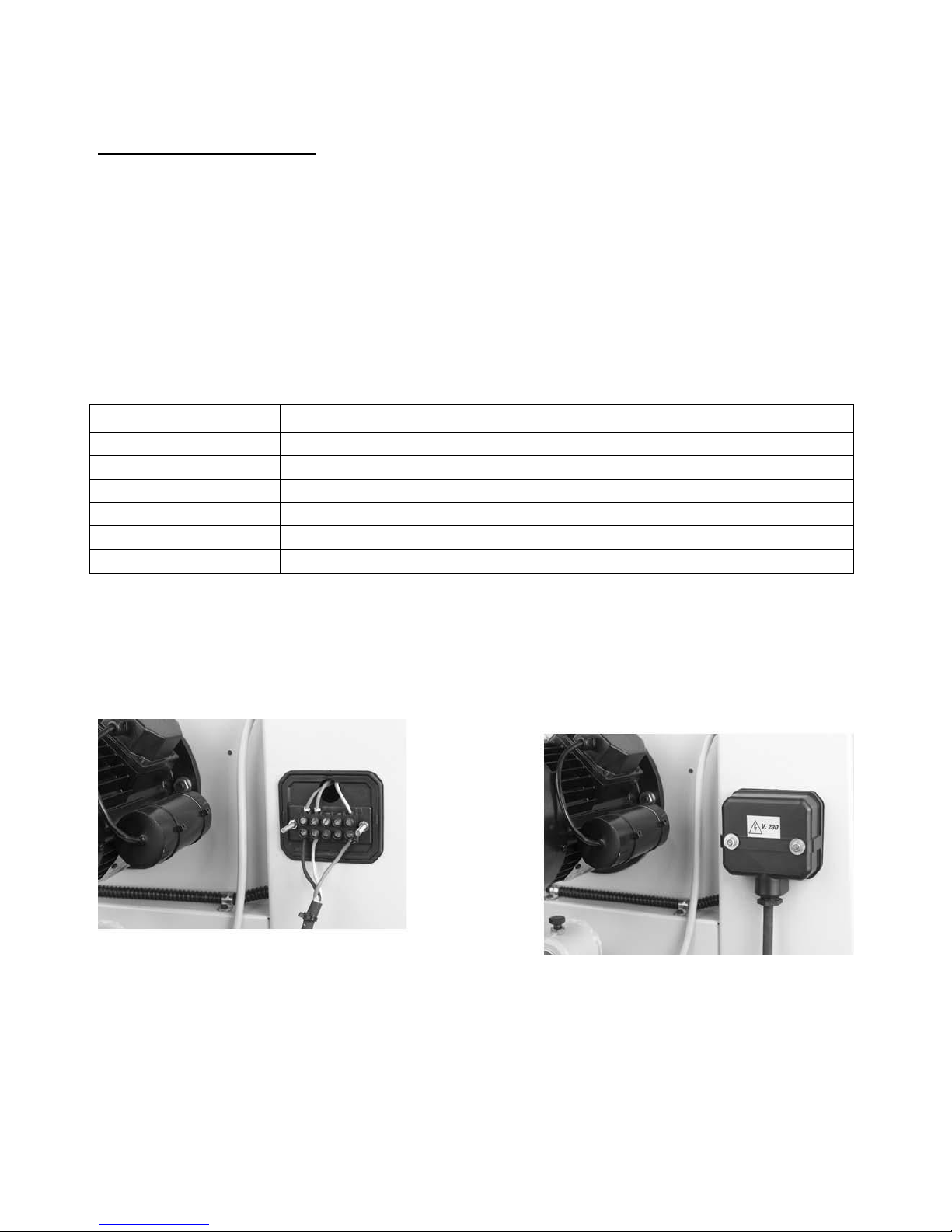
Electrical connection
Note the machine is not supplied with an electrical cord or plug, as the
size of the cable and the type of plug will be dependent on the
installation.
A qualified electrician must carry out the electrical installation. The main
connection should be made using the terminal box shown. Ensure that the
main supply corresponds with that of the machine, single phase or threephases. Use wiring suitable for the power of the motor, which is 230 volts, and
the cable is required.
All machines require the minimum of a 30-amp circuit breaker regardless of
the phase.
Connect the electrical wires to the terminals opposite the wires going to the
machine. On a single-phase machine you will find 3 wires. On a 3-phase
machine you will find 4. On the machine you will see a wire that is yellow and
green, which is the ground wire; the other colored wires are power. In either 1phase or 3-phase it does not matter what color combination you use. Green is
ground; all other wiring is power (there is no neutral). On single-phase the
wiring can be interchanged as you wish; it would not affect the rotation of the

24
motor. The direction of rotation of machines with a single phase supply is
predetermined during production. On a 3-phase machine the lower wheel must
rotate in a clockwise rotation. If it rotates in a counterclockwise direction you
need to swap locations of 2 of the power leads, and it will rotate in the correct
direction.

25
Before starting the machine
1. Read and understand the instruction manual before operating the saw.
2. If you are still not thoroughly familiar with the operation of the
bandsaw, get advice from a qualified person.
3. Make sure the machine is properly grounded and that the wiring codes
are followed.
4. Do not operate the bandsaw while under the influence of drugs,
alcohol, medicine or if tired.
5. Always wear eye protection, safety glasses or a safety shield, and
hearing protection.
6. Wear dust mask; long-term exposure to the fine dust created by the
band saw is not healthy.
7. Remove your tie, rings, watch and all jewelry. Roll up your sleeves;
you do not want anything to get caught in the saw.
8. Make sure that the guards are in place and use them at all times. The
guards protect you from coming in contact with the blade.
9. Make sure that the saw blade teeth point downward towards the table.
10. Adjust the upper blade guard so that it is just clearing the material
being cut.
11. Make sure that the blade has been properly tensioned and tracked.
12. Stop the machine before removing the scrap piece from the table.
13. Always keep your hands and fingers away from the blade.
14. Make sure that you use the proper size and type of blade.
15. Hold the work piece firmly against the table. Do not attempt to saw
stock that does not have a flat surface facing down, unless a suitable
support is used.
16. Use a push stick at the end of a cut. This is the most dangerous time
because the cut is complete and the blade is exposed. Push sticks are
commercially available.
17. Hold the wood firmly and feed it into the blade at a moderate speed.
18. Turn off the machine if you have to back the material out of an
uncompleted or jammed cut.

26
Stop switch in the
on/out position
(should see yellow
ring)
Stop switch in
the off/in
position
Yellow ring showing
No yellow ring
showing
Machine test
Now is the time to test the machine.
1. Close the doors. If you try to start the
machine with the doors open, the machine
will not start, as the safety switch is not
engaged.
2. Check that the foot break is in the fully up
position. The machine will not start if the foot
break is not fully up, as the safety switch will
not be engaged.
3. Check that the red safety switch is in the fully
out position.
4. Check that the machine is clear of all tools
and other loose objects.
5. Check that all the adjusting and locking
handles are tight.
6. Check that there is no blade fitted; it is far
safer to test the machine without a blade
fitted.
7. Start the bandsaw by turning the start switch
fully to the right, and once started release
the switch.
8. The lower flywheel is now turning.
9. Now is the time to check that all the safety
switches are functioning correctly before you
fit a blade. Never complete the following tests
with a blade fitted as it could cause injury.
10. With the machine running [no blade fitted],
operate the foot break. The motor should
have the power removed and the lower wheel
slowed down.
11. With the machine running [no blade fitted],
operate the red stop switch by pressing
towards the machine. The motor should have
the power removed and slowed down.
12. With the machine running [no blade fitted],
open the doors very slowly until the top door
switch functions. The motor should have the
power removed and slowed down. Close the door and wait for the
flywheels to completely stop before you fully open the doors.
13. If any of the safety switches fail to operate correctly, do not use the
machine until the fault has been corrected.

27
Adjusting the bandsaw
Fitting a blade to the bandsaw
A lot of people do not like to change the blades and go to great lengths to avoid
doing it. To use the bandsaw to its greatest advantage, you will have to use the
appropriate blade and track it quickly. This is a habit that can be easily
developed. If you use a step-by-step method of tracking, the procedure should
only take a minute or two. Be careful when using blades, especially wide ones.
Always use gloves and safety glasses.
Installing the blade
Disconnect the power to the bandsaw.
Adjust the side guide and back guide out as far as they will go [both upper and
lower guides]. This will ensure that they do not interfere with the blade while
you are fitting, tracking and tensioning the blade.
1. Uncoil the blade. Remember to use gloves
and safety glasses. The blade may have dirt
or oil on it so by using a clean rag, clean the
blade and pull rearwards so that the cloth
does not hook on the teeth.
2. Inspect the teeth and the general condition of
the blade. If the teeth are pointing in the
wrong direction when you hold the blade up
to the machine, you will have to turn it inside
out. To do this, hold the blade with both
hands and rotate. Remove the table pin.
3. With the hinged guard on the guide support
shaft open and the table insert removed, hold
the blade with both hands with the teeth
towards you. Slide it through the table slot and place it on the wheels.
Hang the blade on the top wheel and then line it up with the lower
wheel. If the top wheel needs to be lowered, rotate the tension handle
wheel.
4. Apply tension to the blade by
adjusting the tension hand wheel.
Do not fully tension the blade at
this stage.

28
5. Start rotating the wheels by hand in the normal direction. As you do
Tracking knob
Check
deflection
here
Tension
gauge
Locking handle
this, watch the blade to
determine where the blade wants
to track. If the blade is tracking
too far forward or backward,
make small adjustments with the
tracking adjustment knob located
at the back of the bandsaw while
still rotating the wheel. Once the
blade is tracking in the correct
position, fully tension the blade
and re-track.
Note: The blade must be fully tensioned for final tracking.
Note: Never track the blade with the saw running.
6. Lock the tracking adjustment handle.
7. Tensioning the blade The blade
tension indicator [mounted on the
vertical post of the bandsaw]; is used
as a general guide, and the following
tensioning procedure is recommended.
Looking at the top wheel, place your
finger at the 9 o'clock position. Move
your finger down 6" and using
moderate pressure with your thumb,
press on the flat of the blade. You
should get 3/16" to ¼" of deflection.
8. Note: If you are not using the bandsaw for extended periods of time
[overnight], remove the tension on the blade. This will increase the life
of your blade and the machine. If tension is left on the machine, flat
spots or grooves can be formed in the rubber of the wheels which will
detract from the performance of the machine and in extreme cases
cause vibration when the machine is run.
9. Close the guard on the upper guide support post. Close the doors
move the door blade guard up and lock in position. Replace the table
insert, and check that the blade moves freely through the table insert.
Replace the table pin. Check that all wrenches and loose parts are

29
removed from the machine.
10. Plug the machine into the power, turn the machine on for a second
and switch off. Watch how the blade runs. If the blade tracks well,
then run the machine at full power.

30
Pin
Removing the blade from the band saw
1. Disconnect the power to the
bandsaw.
2. Remove the pin that aligns the
two table halves.
3. Open the upper-hinged blade
guard.
4. Remove the table insert.
5. Remove the tension on the upper
flywheel.
6. Open the doors and remove the
blade from the wheels [use gloves and eye protection], and gently
slide the blade through the table slot.
Tracking position of the blade on the wheels
Tracking large blades. There has been a lot of discussion on the position that
the blade should be on the wheels. One group of people recommends that with
large blades you should track the blade so that the teeth hang just over the
front edge of the rubber. The second group recommends that all blades
regardless of their size should run in the center of the wheel. The advantage of
running the large blades with the teeth not contacting the rubber of the wheel
is that they cannot damage the tire. The disadvantage is that the wheel is
crowned and the blade is not tensioned in the center of the band, which gives
the blade a tendency to wobble or flutter. The advantage of running large
blades on the center of the wheels is that they are tensioned in the center of
the band and have fewer tendencies to wobble and flutter. The disadvantage is
that blades with a large set on the teeth have a tendency to damage the rubber
of the tire. This does not have a great effect on the performance of the
bandsaw as all blades are running on the center section of the tire which is not
affected. We recommend that you balance all blades on the center of the
wheels for optimum performance and a smoother cut.
Adjusting the blade guides
Introduction
Welcome to a new era in bandsawing. You have purchased a bandsaw with a
revolutionary blade guide system [patent pending] that is designed to give you
years of safe, high quality bandsawing. Most blade guides are designed to
support the blade on the sides and either above or below the side guides the
back of the blade. This can allow the blade to twist as pressure from the wood
 Loading...