

Page 1

Plasma CNC Manual
LAGUNA TOOLS
2072 Alton Parkway
Irvine, California 92606
Ph: 800.234.1976
www.lagunatools.com
MCNC Plasma 48 x 48
MCNC Plasma 48 x 96
MCNC Plasma 60 x 120
© 2018, Laguna Tools, Inc. LAGUNA® and the LAGUNA Logo® are the registered trademarks of Laguna Tools, Inc. All rights reserved.
Rev1 08/25/2014
Page 2

Page 3

Page number
Safety Rules
4
Warranty
5
Noise Emission
6
Specification Sheet
6
Receiving Your CNC Plasma
6
Introduction to Your CNC Plasma
6
Parts of Your CNC Plasma
7
What You Receive with Your CNC Plasma
Where to Locate Your CNC Plasma
Unpacking Your CNC Plasma
Assembly and Setup
Machine Operation
Maintenance and Troubleshooting
Machine Drawing
Wiring Drawings
Table of contents.
3
Page 4

Safety Rules.
As with all machinery, there are certain hazards involved with the operation and
use. Using it with caution will considerably lessen the possibility of personal injury.
However, if normal safety precautions are overlooked or ignored, personal injury
to the operator may result. If you have any questions relative to the installation and
operation, do not use the equipment until you have contacted your supplying
distributor.
Read carefully before operating the machine.
1. Keep the working area clean and be sure adequate lighting is available.
2. Do not wear loose clothing, gloves, bracelets, necklaces or ornaments. Wear
face, eye, respiratory and body protection devices as indicated for the
operation or environment.
3. Be sure that the power is disconnected from the machine before tools are
serviced or an attachment is to be fitted or removed.
4. Never leave the machine with the power on.
5. Do not use dull, gummy or cracked cutting tools.
6. Be sure that the keys and adjusting wrenches have been removed and all the
nuts and bolts are secured.
4
Page 5

Limited Warranty
New machines and accessories sold by Laguna Tools carry a one-year warranty
effective from the date of shipping. Machines sold through dealers must be registered
with Laguna Tools within 30 days of purchase to be covered by this warranty. Laguna
Tools guarantees all new machines and accessories sold to be free of manufacturers’
defective workmanship, parts and materials. We will repair or replace, without charge,
any parts determined by Laguna Tools, Inc. to be a manufacturer’s defect. We require
that the defective item/part be returned to Laguna Tools with the complaint. Any
machines returned to Laguna Tools must be returned with packaging in the same
manner in which it was received. If a part or blade is being returned it must have
adequate packaging to ensure no damage is received during shipping. In the event the
item/part is determined to be damaged due to lack of maintenance, cleaning or
misuse/abuse, the customer will be responsible for the cost to replace the item/part,
plus all related shipping charges. This limited warranty does not apply to natural
disasters, acts of terrorism, normal wear and tear, product failure due to lack of
maintenance or cleaning, damage caused by accident, neglect, lack of or inadequate
dust collection, misuse/abuse or damage caused where repair or alterations have been
made or attempted by others.
Laguna Tools, Inc. is not responsible for additional tools or modifications sold or
performed (other than from/by Laguna Tools, Inc.) on any Laguna Tools, Inc.
machine. Warranty maybe voided upon the addition of such described tools and/or
modifications, determined on a case-by-case basis.
Software purchased through Laguna Tools Inc. is not covered under this warranty
and all technical support must be managed through the software provider. Software is
non-refundable.
Normal user alignment, adjustment, tuning and machine settings are not covered by
this warranty. It is the responsibility of the user to understand basic machinery
operation, settings and procedures and to properly maintain the equipment in
accordance with the standards provided by the manufacturer.
Parts, under warranty, are shipped at Laguna Tools, Inc.’s cost either by common
carrier, FEDEX ground service or a similar method. Technical support to install
replacement parts is primarily provided by phone, fax, e-mail or Laguna Tools
Customer Support Website. The labor required to install replacement parts is the
responsibility of the user.
Laguna Tools is not responsible for damage or loss caused by a freight company or
other circumstances not in our control. All claims for loss or damaged goods must be
notified to Laguna Tools within twenty-four hours of delivery. Please contact our
Customer Service Department for more information.
Only new machines sold to the original owner are covered by this warranty.
For warranty repair information, call 1-800-332-4094.
Page 6

Noise Emissions.
Notes concerning noise emission:
Given that there exists a relationship between noise level and exposure times, it is not precise
enough to determine the need for supplementary precautions. The factors affecting the true
level of exposure to operators are clearly the amount of time exposed, the characteristics of
working environment other sources of dust and noise etc. For example, adjacent machines in
other words the level of ambient noise. It is possible that exposure level limits will vary from
country to country.
Specification Sheet.
Note: The specification will depend on the machine that is ordered. Most
machines are made to order, and therefore, the specification will vary
depending on the machine you require.
Note: This manual is designed to cover the general use of CNC Plasma
machines. CNC machines and some pitchers may be different to the
machine that you receive. The general principles apply to the CNC plasma
machine.
Receiving your machine.
Note. It is probable that your machine will be delivered by a third party. Before you unpack
your new machine, you will need to first inspect the packing, invoice, and shipping
documents, supplied by the driver. Ensure that there is no visible damage to the packing, or
the machine. You need to do this prior to the driver leaving. All damage must be noted on the
delivery documents and signed by you and the delivery driver. You must then contact the
seller, Laguna Tools, within 24 hours.
6
Page 7

Introduction to CNC Plasma machines.
The CNC Plasma is designed to give you years of safe service. Read this owner’s manual in
its entirety before assembly or use.
The advantage of the CNC Plasma machine is that it can, in most cases, fully machine the
complete job without it being removed from the table so that you have finished parts of high
accuracy that are totally repeatable.
Nesting is also a valuable feature of CNC Plasma machining that saves on waste and costs.
What is Plasma?
Plasma is a gas heated to an extremely high temperature and ionized so that it becomes
electrically conductive. Plasma arc cutting uses the plasma as an electrode to transfer a
electrical arc to the work piece. The heat of the arc melts the work piece and the force of the
plasma and shield gases blow away the molten metal to cut the work piece.
Different metals react differently to plasma cutting. Carbon steel can be oxidized, and is
usually cut with a plasma containing oxygen to take advantage of the exothermic process.
Higher levels of oxygen in the plasma result in higher heat and higher rates of oxidation. The
result is a faster and cleaner cut. Stainless steel and aluminum are not subject to rapid
oxidation and depend entirely on the plasma’s heat for the cutting process. Because plasma
produces much higher heat than the oxygen-fuel cutting process, plasma can cut stainless
steel and aluminum quickly and cleanly.
History of plasma:
Half a century ago Thayer Professor James Browning ’44 was nicknamed Hanover’s firebug
for his study of flame stability and combustion at Dartmouth college.
Browning will be remembered best for inventions that fired up the N.H. Upper Valley economy.
In the 1950s he created a plasma torch that produced flames twice as hot as the sun’s
surface. Passing nitrogen or hydrogen through a high-intensity electric arc, the torch cut metal
like butter. Browning and Thayer colleague Merle Thorpe founded Thermal Dynamics Corp. to
manufacture the device. Within three years the start-up had sales of $1 million. A decade
later, Thayer Professor Robert Dean and Richard Couch ’64, Th’65 formed Hypertherm Inc.
7
Page 8

Caterpillar track Gantry Plasma head
Controller/Electrical cabinet Oiler Frame Supporting feet
Parts of the CNC Plasma
8
Page 9

Caterpillar track Plasma head Bed
1. Bed.
The bed of the machine consists of a heavy steel frame with a steel supporting plates. The
supporting plates are designed to give point contact with the job and are consumable as they
will be cut by the plasma cutting head.
2. Gantry.
The gantry straddles the bed and carries the Plasma cutting head motion system. It is moved
along the length of the bed by a precision rack-and-pinion system that is controlled by the
machine controller.
3. Plasma cutting head.
The plasma cutting head is moved along the gantry by a precision rack-and-pinion system
that is controlled by the machine controller. The plasma cutting head is moved vertically by a
precision ball screw system that is controlled by the machine controller.
4. Frame.
The frame is a heavy welded construction that supports all the other parts of the machine.
5. Controller/Electrical cabinet.
The Controller/Electrical cabinet is located on the side of the machine. The enclosure houses
all the electrical components for controlling and powering the machine.
6. Caterpillar track.
9
Page 10

The caterpillar track runs along the side of the machine and across the gantry in a trough and
carries all the electrical cables and gas pipes.
7. Oiler.
The oiler connects to all the relevant slides on the machine and when pumped by hand will
lubricate all the relevant slides.
8. Supporting feet.
There are supporting feet that are used to level the machine.
Additional instructions for the use of the CNC Plasma
Like all machines, there is danger associated with the machine. Injury is frequently caused by
lack of knowledge or familiarity. Use this machine with respect. If normal safety precautions
are overlooked or ignored, serious personal injury may occur. As the CNC is under the control
of the onboard machine controller, it is important that you are clear when operating the
machine.
What you will receive with the machine.
What is supplied with your machine will depend on the specification of the machine
and extras that you order.
Where to locate your machine.
Before you unpack your machine, select the area where you will use your machine. There are
no hard-and-fast rules for its location, but below are a few guidelines.
1. There should be an area around the machine suitable for the length of job that you will be
cutting.
2. Adequate lighting. The better the lighting, the more accurate and safely you will be able to
work
3. Solid floor. You should select a solid flat floor, preferably concrete or something similar.
4. Close to power source.
10
Page 11

Lock nut
Supporting foot
Supporting foot
Unpacking your machine.
To unpack your machine, you will need tin snips, knife and a
wrench.
1. Using the tin snips, cut the banding that is securing the
machine to the pallet (if fitted).
WARNING: EXTREME CAUTION MUST BE USED
BECAUSE THE BANDING WILL SPRING AND COULD
CAUSE INJURY.
2. Remove the box from the CNC machine if fitted and any
other packaging material. The parts ordered with the machine
will be packed on or inside the machine.
Note: The machine is heavy, and if you have any doubt about
the described procedure, seek professional assistance. Do not
attempt any procedure that you feel is unsafe, or that you do not
have the physical capability of achieving.
3. Use a forklift with sufficient lifting capacity and forks that are long
enough to reach the complete width of the machine.
4. Remove the securing bolts that attach the machine to the pallet
(if fitted).
5. Approaching the machine from the side and lift the machine on
the frame, taking care that there are no cables or pipes in the area
of the forks.
6. Move the machine to the required position and lower gently to
the floor.
7. Level the machine so that all the supporting feet are taking the weight of the machine and
no rocking is taking place.
11
Page 12

Assembly and set up.
Cleaning the machine.
The machine is shipped with the non-painted surfaces protected from rust by a film of grease.
The grease must be removed with WD40 or similar, as it attracts dirt. The surfaces should
then be coated with a 30W oil or wax and any excess removed.
Electrical connections for the machine.
The main power cable and has no plug fitted, as it will be dependent on your installation.
Ensure that when installing the electrical supply to the machine that 220v three-phase is
supplied. It is not possible to recommend a breaker size, as this will be dependent on the
specification of the machine that you purchase.
Note: When wiring the machine to your electrical system, keep your cable as short as
possible, and the cable should not be allowed to run along the floor, as this will cause a trip
hazard.
Note: A qualified electrician must carry out the electrical installation.
Shielding and Grounding.
This section is preliminary and offers only typical shielding and grounding techniques to
reduce RF noise. As with all electrical devices it is important to always follow all local
electrical codes including but not limited to the National Electrical Code.
12
Page 13

Motor controller and other controls.
Keep the motor controller and other controls as far from the plasma power supply as possible.
Plasma Power Supply.
Place the plasma power supply and/or remote arc starter at the rear of the frame. Keep the
CNC computer controller as far from the power supply and/or remote arc starter as possible.
Follow the power supply grounding diagram found in the system manual.
13
Page 14

14
Page 15

Grounding Connections.
Pilot arc starting generates a certain amount of electromagnetic interference (Called EMI).
This is commonly called RF noise. This RF noise may interfere with other electronic
equipment such as the CNC controller and other equipment in the vicinity. To minimize the RF
interference the following grounding procedures should be followed when installation of the
machine is undertaken.
Drive 5/8" diameter X 10 feet long copper clad steel earth rod as close to the table as
possible. It may be necessary to weld a second rod to reach the moisture layer to achieve a
proper ground. Follow the attached instructions for proper earth ground rod testing. If multiple
ground rods are required to achieve proper grounding keep a minimum distance of 1.1 times
the driven length between driven rods.
Note: Keep ground wires as short as possible. Remove any paint, rust or oxide from
the connection point. Always use star washers and electrical anti corrosion paste on
all connections.
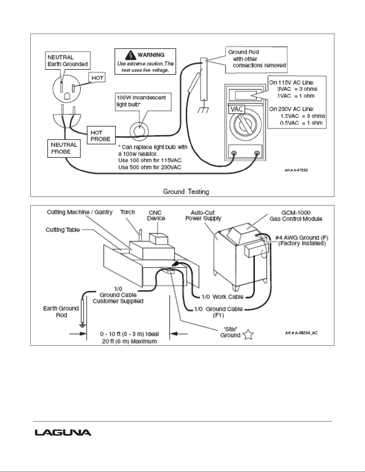
Create a main star ground on one of the table legs. The main star ground will be the only
point where all grounding wires will terminate before the earth ground rod. The point should
have good metal to metal contact and provide a sufficient number of ground lead attachment
points to eliminate the need to stack lead terminals, see figure 2 below. Connect a minimum
1/0 AWG cable (4/0 is best) from the star to the earth ground rod. Do not connect any other
grounds directly to the ground rod.
Create an auxiliary star ground point as needed to connect ground leads from moving points
of the table to the main ground. The point should have good metal to metal contact. Connect
this star to the main star using #4 AWG minimum.
Connect the power supply safety ground directly to the main star ground with a minimum 1/0
cable.
Connect the remote arc starter directly to the main star ground with a minimum 1/0 cable.
15
Page 16

Fig. 2 Avoid stacking terminal lugs
Testing for proper Grounding.
To Test for a proper earth ground refer to the following diagram. Ideally, the reading on the
multimeter should be 3 VAC for 115VAC or 1.5VAC for 230 VAC line.
Note: Increasing the ground rod length beyond 20-30ft (6.1- 9.1m) does not generally
increase the effectiveness of the ground rod. A larger diameter rod which has more surface
area may help. Sometimes keeping the soil around the ground rod moist by continuously
running a small amount of water into it will work. Adding salt to the soil by soaking it in salt
water may also help to reduce its resistance. When you use these methods periodic checking
of the ground resistance is required to ensure that the ground is still good.
Note: Keep the torch leads clean . Dirt and metal particles bleed off energy, which causes
difficult starting and increases chances of RF interference.
16
Page 17
17
Page 18

Shielding.
Single Shield Method (Good):
Connect the shield/drain of a shielded cable to ground at the sensitive equipment end and
leave the other end of the shield disconnected.
Cover all non-shielded cables with a tightly woven braided shield. Slide the shield over the
cable leaving enough to slide back over the electrical connectors and terminate only the one
end to the sensitive equipment side ground. Use a metal cable clamp to attach the shield to
the ground. See Figure 3.
Double Shield Method (Better):
Cover all shielded cables with a tightly woven braided shield. Slide the shield over the cable
leaving enough to slide back over the electrical connectors. Use a metal cable clamp to attach
the shield to the nearest ground at both ends of the cable. See Below Figure.
Clamp On Ferrite Cores:
Use a clamp type ferrite core on the following cables:
Wall Mount Transformers
RS232 Cables (as an alternative, fiber optic converters will offer the best noise
immunity)
Computer and Motor Controller AC power cord
Control cables and encoder cables
18
Page 19

I/O cables
Open the ferrites clamp and pass 4 to 10 turns around one half of the core then close and
snap the clamp shut. Ferrite cores are not recommended for use with braided shielding.
Other:
If cables must cross ground wires or at worse case torch leads do so at 90 degree
angles.
Select a power outlet rated to support the devices that will be connected.
Avoid connecting the cutting table to multiple AC power outlets. Use one outlet with a
good surge suppression device and multiple power outlets.
The Plasma Power Supply may be connected to a different power outlet however it is
best if the outlet is common to the same panel as the cutting table.
Do not coil wires and cables. If you need to clean up the install do so by wire tying the
loops of extra cable so the major length of the cable is touching. Remove as much air
gap as possible from the cable bunch. See Below Figure.
This does not apply to Ground cables, always cut ground wires & cables to minimum
required length.
Route ground cables as far apart from control cables as is possible. Keep cables that
run in parallel (i.e. in the same power track) with the ground separated by as much air
space or other gas hoses as possible.
HF (High Frequency) travels on the outside of a wire. Increasing the diameter of the
ground wire or using flat braid for ground wire will improve the ability to carry the HF to
ground.
19
Page 20

Z axis home switch
Y axis home switch
X axis home switch
Y axis home switch
X axis home switch
Machine Operation.
Home switches.
There are three switches that determine the home position of the cutting head.
The switches are factory set, and no adjustment should be required. If adjustment is required,
contact your service technician prior to conducting any adjustment.
20
Page 21

Emergency stop button Electrical On/Off switch
Display USB socket
Control Panel.
The control panel houses the main interface to the machine.
1. Display.
2. USB socket. This is used to input programs into the controller.
3. Emergency stop button.
To reset the emergency stop, twist clockwise and it will pop out.
4. Electrical On/Off switch. The electrical On/Off switch connects the controller to the electrical
supply and starts the processor.
Loading a program into the machine.
1. Load your program into your USB drive.
2. Fit the USB into the USB slot.
3. Press the PROG. button. This will take you to the program page.
4. Press ACCESS USB button. The "active program" box will display the name of the first
program on your USB.
5. Use the arrow keys to select a file.
6. Press the copy button to copy the file.
7. Press Access Card button.
21
Page 22

8. Use arrow keys to select a file.
9. Press RUN button to go to the run screen
10. Ensure that you are cleared of the machine. Wear Proper flash protection for your
eyes.
11. Press START button. The machine will start running the G code
Turning on the Machine.
Note: Before you turn on the machine, remove all tools and other objects from the machine
table.
Release the emergency stop by twisting clockwise, and it will pop out.
Turn the On/Off switch to turn the power on. The display will light up.
Press HOME MACHINE button
Make sure that the table surface is clear of obstructions.
The head will move to the home position on the table.
Do's and Don'ts.
1. DO lubricate all ball screws every 8 hours of run. Use 30w oil or lithium white grease
lubricant or equivalent to lubricate the ball screws and wipe off any excess to reduce dirt and
dust acumination.
2. DO NOT ever under any circumstances reach over the table or obstruct the movement of
the gantry while the machine is powered or running a program.
3. ALWAYS press in the E-STOP button on the control box and turn off main power prior
conducting any maintenance. Remember to clear alarms caused by the E-STOP button on
the alarm pages after the E-STOP has been removed.
4. The E-STOP button MUST be out before turning on the main power (twist and it will pop
out).
22
Page 23

Alarms Tools Start Prog Man Run
Hold Stop Jog Pos Jog Neg
Membrane Button Descriptions.
Alarms. This is a page jump to the first Alarm Screen.
Tools. This is a page jump to the first Tool Screen.
Start. This button is for starting the program shown in the active Program screen.
Hold. This button is used to pause a running program. To release Hold, press the start
button, and the program will continue.
Stop. This button Stops the active program.
Run. This button is a page jump to the first Run (home) screen.
Man. This button is a page jump to the first Manual screen
Prog. This button is a page jump to the first Program screen
Jog Pos. This button jogs the selected Axis in the positive direction.
Jog Neg. This button jogs the selected Axis in the negative direction.
23
Page 24

Screen overview
24
Page 25

Run Screen.
1) Homing the machine is the first step every time power is applied. No functions or actions
can occur until homing is complete and successful.
2) (Active Program) field shows the current program loaded for run.
3) (Feed Rate) and (Spindle RPM) indicate the programmed rate and speed during a
program run..
4) (Start at Tool) allows the operator to start a program from a specific tool in a multiple tool
program.
5) (Machine Coords) is a drop-down menu to select which dimension set is shown in the X, Y,
Z, and A axis DROs. The displayed references are for Machine Coordinates, Zero Point
Offset (G54), and relative coordinates.
6) (OVERRIDES) button is for a page jump to the overrides available while the program is in
run.
7) (PLASMA) button is for a page jump to the second Run screen where the operating
parameters for Plasma cutting are set.
25
Page 26

Run 2 Screen.{PLASMA SET-UP,1)
The following fields are propagated from the cut chart provided by your Plasma power supply
manufacturer.
NOTE: The settings are a starting point only. Metals vary greatly and so adjustments for total
performance are generally required.
1) {PIERCE HEIGHT}: This is the distance the torch will ignite from the metal plate as
detected by plate touch off that can occur before every ignition.
2) {CUT HEIGHT}: This is the distance from the plate that the torch will move to for the
material during the cutting process.
3) {PLASMA FEEDRATE}: This is the cutting federate from the cut chart based on material
thickness and Amperage setting of the power supply.
4) {PIERCE DWELL}: This is the time delay the torch stay’s at the pierce height to pierce
through the plate based on the chart.
5) {PID SCAN}: This is the scan time adjustment for fine tuning the height control system.
Unless you’re a very high end user there is no reason to adjust this parameter.
6) {ARC SAMPLE DELAY}: This is the delay from the movement to cut height until the
system takes a sample of the arc feedback for the height control. For instance if you’re
starting on an incline you want the sample to be taken sooner so the torch stays above the
material correctly. Most cases this does not need to be adjusted providing you have cammed
the vectors with an intelligent starting point.
26
Page 27

7) {EXECUTE TOUCH OFF}: Pressing this button will make the machine find the top of the
plate. Execution of touch off will slowly lower the torch until there is continuity between the
Ohmic clip on the torch and the grounded plate on the machines table.
Make certain the torch tip is clean and there is no scale or filth layer to inhibit continuity.
8) {CHECK CODE} Press this button prior to starting your program and the controller will pre-
run the code looking for errors prior to starting the program.
27
Page 28
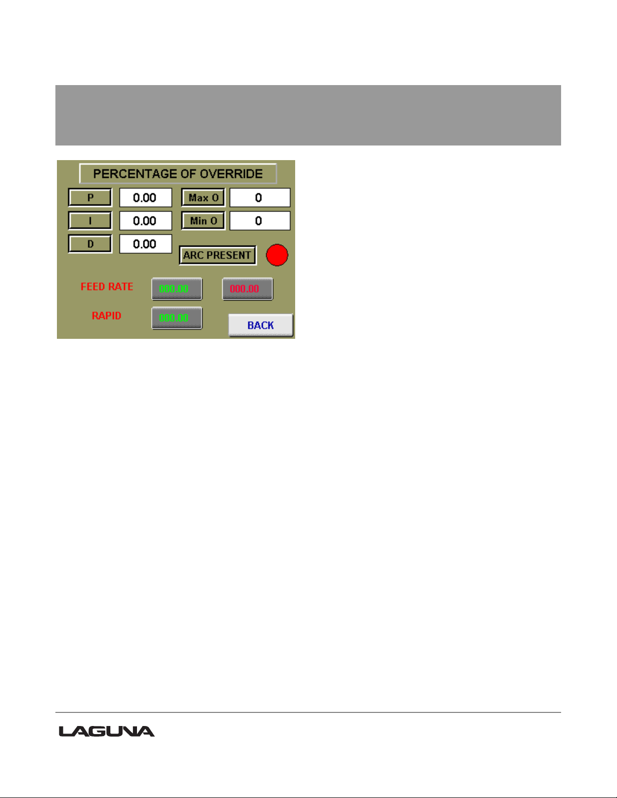
Run Overrides Screen.(Plasma Setting’s,2)
The green numbers are fields that can be used for entering a percentage above and below
the programmed rates of feed and speed.
The red numbered fields show the current rates of feed and speed.
The field (RAPID) is used to restrict the machines feed rate by a percentage when a G0
(Rapid Move) is called in a program.
P,I, AND D FIELDS: These are a very high end user function’s.
For 98% of your cutting the default settings are perfect.
These are the height controllers PID loop control settings and should only be adjusted by
competent personnel.
MAXO AND MIN O: These are the max velocities of Z during the use of the height control
system. These too should only be adjusted by qualified personnel.
FEEDRATE FIELD: This is an Override for the feed rate during a program run, If you have
set feed rate wrong this allows for adjustment during the cutting process. The adjustments
are in percentage of the original federate that was set on the plasma set-up page.
The green is the percentage of change and the red field is the real time feed rate feedback
after adjustment.
RAPID Field: This an override for the G0 rapids that are moves between cuts. There are
times an operator would like to have more time between torch ignitions.
28
Page 29

Manual Screen 1 (Jog control).
1) (CONT. JOG) When pressed, selects a continuous jog mode based on the percentage of
full speed chosen under (JOG SPEED).
2) (STEP JOG) When pressed, selects a step jog mode based on the resolution chosen
under (STEP SIZE).
3) (X-AXIS, Y-AXIS, Z-AXIS, AND A-AXIS) Buttons are used to select the axis you wish to
jog.
4) (JOG PAST Y-SAFE) Button allows the operator to jog past the Y-safe dimension, i.e., just
before the tool rack.
5) The (NEXT) button is used to jump to the second manual screen for MIDI functions.
29
Page 30

Manual 2 Screen.
1) This screen is used for MIDI functions; this is when an operator needs to run a single line
of G code at a time. This can do manual tool changes and move any axis to a specific
location in the table.
Press on the pink command window, and an alpha-numeric pad will pop up for MIDI string
entry.
With the string entered, press (EXECUTE MIDI) to run.
30
Page 31
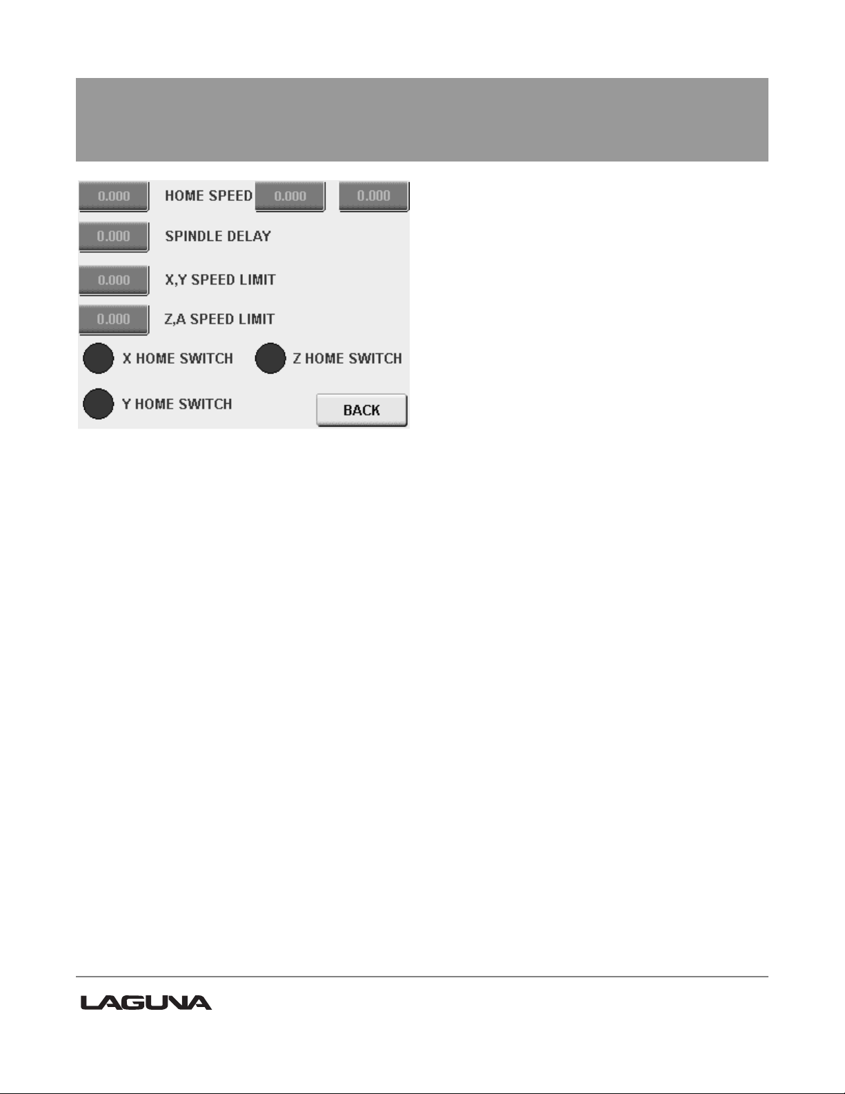
Manual 3 Screen.
1) The top three fields are for setting the Home speeds, from left to right is X, Y, and Z.
2) (SPINDLE DELAY) is the time the program waits for the spindle to become at speed
before cutting begins.
3) (X, Y SPEED LIMIT) is the top speed the controller will rapid at when 100% of feed rate is
required.
4) (Z, A SPEED LIMIT) is the top speed the controller will rapid at when 100% of feed rate is
required.
5) The lower indicators are used to verify the individual home switches are functioning
correctly, you can flag the home switches with something ferrous and activation will show
on the corresponding light on the screen.
31
Page 32

Program Screen.
1) (Active Program) field displays the current program selection.
2) (ACCESS USB) Opens the inserted USB with stored programs.
3) (ACCESS CF CARD) Opens the list of stored programs on the controllers CF card.
4) (COPY) Button moves a program from either the network or the USB to the CF card on
the controller.
5) (DELETE) Button is used for deleting programs from SD card.
6) (UP)/(DOWN) Buttons are used for scrolling through the stored programs in the location
selected.
32
Page 33

Coord's Screen.
1) (Machine Coords) is a drop-down menu to select which dimension set is shown in the X, Y,
Z, and A axis DROs. The displayed references are for Machine Coordinates, Zero Point
Offset (G54), and relative coordinates.
2) (RESET RELATIVE) is a built-in tape measure. By pressing the RESET REATIVE button,
you will zero the X- and Y-axis DRO under relative coordinates display. You can then jog
from there to get precise measurement when needed. This function does not affect
machine or zero point offset locations.
3) (TEACH ZPO) Teach Zero Point Offset is used to set the work offsets the program will
reference during run (G54 is generally the front left corner of the spoil board). Jog to the
front left corner in X and Y and press the (TEACH ZPO) button.
4) The next button will jump to the Export and Import settings screen.
33
Page 34

Coord's 2 Screen.
1) This screen is used for exporting all user and factory machine settings in a machine
settings .xml file for backup.
This is needed if the flash card (operating system) is replaced or upgraded.
Simply insert a USB memory stick and press export. A file called “machine settings” will
be generated. It is suggested you save this file securely so a rebuild or upgrade can be
done quickly without resetting up the machine and its saved locations. Tool touch-off
data is the only information not backed up, but once the tool touch-off is automated, it
is easily repeated.
34
Page 35

Tools Screen.
The tools screen is where the operator can turn on and off the various plasma function s built
into the B+R controller.
1) (EXECUTE TOUCHOFF) Button starts a torch touch-off routine to measure the Torch to
Plate {Z zero distance}. Pressing this button starts to lower the Z axis down until continuity
between the torch tip and the Plate to be cut.
The distance the Z travels in Rapid before slowing is set in the {Z Pre field}.
2) To manually set the torch distance for Z Zero. Jog the Z axis until it contacts the plate.
Press (Teach Tool Length), then press (SET TOOL DATA) to set.
NOTE: THE TOUCHOFF DOES NOT MOVE TO A LOCATION FOR THIS FUNCTION, IT
LOWERS WHERE EVER THE OPERATOR HAS JOGGED THE TORCH OVER.
3)HEIGHT CONTROL OFF BUTTON:
This feature cancels the Height control system when it is not required. This is very helpful on
flat plates where you want to go very fast. The height control has issues over 70- 80 IPM
depending on the metal.
4)TTO OFF BUTTON: This button cancels the automatic torch touch off system that finds the
top of the plate before every ignition. When you’re doing thick flat material cancelling this
feature will quicken you program considerably., When your material is not flat or is changing
with heat it is best to use the TTO so the torch is always at the exact distance from the plate
for the best cut quality and consumable life.
5)ARC PRESENT OVERRIDE: This button cancels the controllers need for Arc verification
from the plasma power supply. This is useful when cutting expanded metal or cutting very
35
Page 36

small parts free with many separate ignitions. If Arc present is enabled the control system
waits for arc present and if there is no signal the program faults out. This is also needed to be
canceled if cutting with a torch or a system without the feedback signal.
36
Page 37

Tools 2 Screen.
1) (ZSPOIL) is used when there is a spindle present for standard routing. This is used to
offset the tool length when required.
2) (ZHOME) This is a Negative dimension for the Torch distance from the Home switch.
This is the Height the Torch will travel at between Moves within a program.
3) (Zmeasure) Is used with a spindle and TTO touch off switch set-up only.
4) (Z Puck) This is used for a spindle application where a puck is used for measuring tool
length.
5) (Zpre) is used with the Torch Touch off function and the TTO for spindle cutting. This is
the dimension the Z axis will rapid to before slowing when looking for the Plate Z zero
distance. Pierce height and Cut height both are measured from the top of the plate when
discovered during TTO.
37
Page 38

Coord,s 3 Screen (coord,s set-up)
1) The left side fields are for setting the positive and negative limits of each axis’s travel.
2) The right side of the screen is used to set up a home network for file transfers and remote
control via VNC from another computer on the network.
38
Page 39
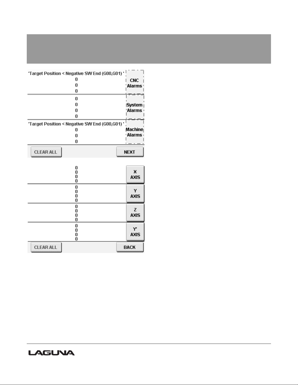
Alarm Screen 1 & 2.
Note: Whenever something is wrong with the machine or the Operator has tried to operate
outside the machine’s parameters there will be a message on one of these alarm screens.
The first screen represents CNC, System, and Machine faults. The second screen represents
Axis errors.
If the error cannot be reset with the (CLEAR ALL) button, then contact Laguna Tools
Customer Service department for assistance.
39
Page 40

1. Control panel
2. Network hub
3. Ethernet cable
4. Ethernet cable connected to screen
5. Screen seen from inside of control
cabinet
6. Ethernet cable connected to
network hub
Getting Started.
Ethernet connection.
40
Page 41

Store IP address in safe place
Control panel battery compartment
Battery cover removed
You need FILE ZILLA software to be able to transfer files.
Real VNC viewer 4 to view machines on your computer
Control Panel Back up Battery..
To replace the control panel has a backup battery.
1. Remover the control panel from the electrical control cabinet.
2. Release the battery cover and remove.
3. Pull the tab and remove the battery. Note the +_ position of the battery.
4. Replace the battery, ensuring that it is inserted in the correct orientation.
5. Replace the battery cover and refit the control cabinet.
41
Page 42

M-
Function
Sync /
Async
In
Use
Description
0
Sync
Yes
Predefined: Programmed Stop
1
Sync
Yes
Predefined: Optional Stop
2
Sync
Yes
Predefined: End of Main Program / Subprogram
3
Sync
Yes
Spindle On
4
Sync
No
5
Sync
Yes
Spindle Off
6
Sync
Yes
Tool Changer - executes subprogram brtc.cnc
7
Sync
No 8
Sync
Yes
Dust Hood Up On
9
Sync
Yes
Dust Hood Up Off
10
Sync
Yes
Open Grip On
11
Sync
Yes
Open Grip Off with check for tool in spindle
12
Sync
Yes
Open Grip Off with no check for tool in spindle
20
Sync
No
Turns on mister output
21
Sync
No
Turns off mister output
29
Sync
Yes
Predefined: End of Main Program / Subprogram
30
Sync
Yes
Predefined: End of Main Program / Subprogram,
turns off Digital Outputs
31
Sync
Yes
DO_SPINDLE_RET = 1,
DO_DRILL_MOTOR_EN = 1
M-
Function
Sync /
Async
In
Use
Description
32
Sync
Yes
DO_DRILL_MOTOR_EN = 0, DO_DRILL[110]_EXT = 0, DO_SPINDLE_RET = 0,
DO_SPINDLE_EXT = 1
33
Sync
Yes
DO_DRILL_[1-10]_EXT = 1 (based on
TFunctionValue)
34
Sync
Yes
DO_SPINDLE_RET=1, DO_SPINDLE_EXT=0
35
Sync
Yes
DO_DRILL_[1-10]_EXT = 0
50
Sync
Yes
Engages the Tangental Tool for Tangental
Machines,
M Code.
42
Page 43

51
Sync
Yes
Engages Slide Drills on SS2_MT_3SLIDES
Machine with Z-Offset
52
Sync
No
Disable Z-Safe Position Offset and Disengage
Slide Drills
100
Sync
Yes
Rotates rack to empty position (tool in spindle)
101
Sync
Yes
Extends tool rack
102
Sync
Yes
Rotates rack to new tool position
103
Sync
Yes
Retracts rack
200
Sync
Yes
A Axis free run - MoveVelocity command
201
Sync
Yes
Stop A Axis
202
Sync
No
203
Sync
Yes
Plasma - DO_START_ARC = 1
400
Sync
Yes
Tangent Axis - move Z-Axis Offset to TanSafe
position for tool
401
Sync
Yes
Disable Z-Safe Position (return Z-offset to 0)
500
Sync
Yes
HMI_IF.Input.Command.RequestDisabledMode
= 1
550
Async
Yes
Invalid Tool Alarm
600
Async
Yes
ARC_SAMPLE delay
700
Async
Yes
Vision System
43
Page 44

G Code.
44
Page 45

45
Page 46

46
Page 47

Maintenance.
As with any machine, to ensure optimal performance, you must conduct regular maintenance.
Torch Maintenance.
See the torch manual that is supplied with the torch.
Lubrication.
You must regularly (minimum every 12 hours) lubricate the bearing surfaces and the ball
screws. Use a thin Lithium spray or a 30wt oil lubricant. Spray daily and wipe off the excess.
Daily Checks.
1. Clean the machine and lubricate unpainted surfaces with a 30wt oil lubricant. Wipe off any
excess and buff with a dry polishing cloth. This will reduce the likelihood of rust forming.
2. Generally inspect the machine for damage and loose or worn parts.
Weekly checks.
1. Generally inspect the machine for damage and loose or worn parts.
2. Check that all the electrical connectors are fitted correctly and are not loose.
3. Check that all the motor couplers are connected and that the screws are tight.
47
Page 48

Central oiler
Position of Home Switches.
The home switches are activated by proximity to steel items
and can be tested by placing a screwdriver or something
similar on the activation face (top). When activated, an LED
should light. If the LED does not come on, the switch or wiring is faulty.
Oiling the Machine.
The machine is provided with a central oiler. Do not over-lubricate
the machine, as the excess oil attracts dirt.
It is recommended that one pump of the oiler once a month will be
sufficient to keep your machine lubricated. When the oil tank needs
filling, top up with a good quality SAE 30wt oil.
48
Page 49

B& R controller
PLC rack
Drivers
Termination block
Components inside the Electrical Control Box.
49
Page 50

Front electrical panel
VFD
[Variable Frequency Drive]
72V p.s.
Breaker Fuses 24V power supply
Main Isolation switch
EMI filter
50
Page 51

Troubleshooting.
Machine will not start.
1. Check that the start switch is being pressed full in.
2. Check that the red emergency stop switch is fully out.
3. Check that the electrical power cord is plugged into the power outlet.
4. Check that the electrical supply is on (reset the breaker).
5. With the power disconnected from the machine, check that the wiring to the plug is correct.
Check that the rubber insulation is stripped enough and is not causing a bad connection.
Check that all the screws are tight.
Stepper motor tries to start but will not turn.
1. With the power disconnected from the machine, try to turn the relevant motor by hand. If
the motor will not turn, check the reason for the jamming.
2. Motor faulty. Replace the motor.
3. Check that the voltage supplied to the machine is 220V.
Squeaking Noise.
1. Check the bearings.
2. Check pulleys and belt for correct tension.
Machine Vibrates.
51
Page 52

1. Machine not level. Re-level the machine, ensuring that it has no movement.
Machine will not home.
1. Are the home position sensors connected, damaged or out of adjustment?
2. Are the parameters in the controller correct?
3. After completing the job, press OK button and check if the cutting head returns to the home
position?
Jobs are not cut consistently.
1. Check that the motor drive belt is tight and not damaged. If damaged, replace.
2. Check if the drive couplings are tight or damaged. If loose, tighten; if damaged, replace.
3. Check if the slider bearings are fixed tight or damaged. If loose, tighten; if damaged,
replace.
Inaccurate Position of the cutting head.
1. Check that the drive screw and the bearing rails are clean and lubricated.
2. Check if the gantry head movement is too fast.
3. Check that all the bearings and motor fixing bolts are tight.
4. Check the input voltage is correct; it must be 220V.
5. Check that there are no obstructions on the gantry.
The Controller Screen is Blank or Dull or Flickers.
1. Check if a fuse has blown.
2. The cable is damaged. Replace the damaged part.
3. The power supply is damaged. Replace the power supply.
4. The controller is damaged. Replace the controller.
5. The supply voltage is not within specification.
52
Page 53

Note: The power must only be 24V.
The Gantry or cutting torch will not function.
1. Controller cable loose.
2. Drive wires loose or damaged.
3. Controller damaged.
4. E-stop is not in the out position. Re-set the E stop.
For technical support contact Laguna Tools at
1-800-234-1976
or
email Laguna Tools Customer Service at
customerservices@lagunatools.com
Please input machine type in subject line.
53
Page 54

Vcarve Pro software
The following is a document outlining the basics of Vcarve Pro for posting code to the Laguna
Plasma machine with B+R controller. There are many Vectric videos and tutorials available
on your CD and online to further your skills in the software. Laguna offers several video’s on
their website for cutting examples as well.
To begin with we need to define the material and some parameters:
1) Set your material size.
2) The plasma post processor does not post Z axis moves. All the Z axis moves are
configured in the Touch screen and based on information from the plasma cut sheets.
3) Set the Datum position, this is your working X and Y zero point offset. Machine zero is
your home switch locations and your work zero is where the codes X and Y moves are
measured from.
4) Select your units of measure.
54
Page 55

Let’s add a graphic to the work area to be cut. You can either draw in Vcarve or import
vectors or DXF files created in other drawing software.
55
Page 56

NOTE: In order for a plasma CNC to create a sharp point as needed in this star graphic we
must add a pass by vector using the fillet command built into the software.
56
Page 57

Now with the graphic adjusted we need to configure the Profile toolpath.
NOTE: You must cut on the line when using the Plasma fillets so it does not try to cut the pass
by loops independent to the star graphic. When Cutting parts to size then cut either inside or
outside the line depending on your application.
57
Page 58

58
Page 59

59
Page 60

60
Page 61

NOTES;
1) Tool Diameter is defined in the Plasma Cut Charts. Look up your amperage and material
thickness for the plasma flame diameter (Kerf)
2) Cutting parameters have no effect on Plasma cutting because the Z axis moves are
handled in the machine controller. Vectric however needs these fields filled in, so use
what is shown to make the field’s happy.
NEXT: CONFIGURE THE REST OF THE PROFILE TOOLPATH AND CALCULATE
ONTO THE SELECT VECTORS.
61
Page 62
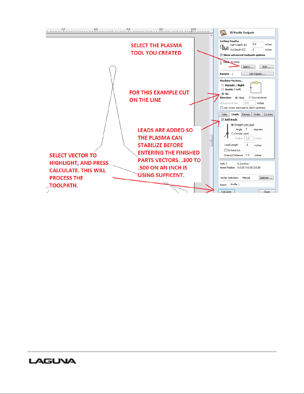
1) Select the Plasma tool you just created.
2) Select on the line cutting for this example.
3) Leads are added to have the arc stable before entering the finished parts cutting area. .3
to .5 of an inch depending on your application and material.
4) Select the graphic to be cut.
5) Press calculate to process the toolpath to the select vectors.
NOW LOOK AT THE CUT PATH SHOWN IN THE DRAWING’S TAB:
62
Page 63

NOTE: The start point has to be adjusted in order to get a proper lead. This is done using
node editing shown below.
SELECT NODE EDITING SHOWN BELOW;
63
Page 64

AFTER SELECTING THE NODE EDITOR, CLICK ON THE VECTOR YOU WISH TO
MODIFY AND THE CURRENT NODES WILL BECOME VISIABLE, Shown Below;
1) While in Node editing right click on a straight portion of the vector and select, (Insert a
Point).
2) Hold over the new node you added and right click the mouse again to select (Make Start
Point).
3) With the new node now green showing it’s the start point. You then need to re-calculate
the tool path and the lead can then be added properly to give the ARC stability before
entering the finished cut path.
64
Page 65

65
Page 66

66
Page 67

67
Page 68

NOW that the tool path is corrected and a useable lead is present, you need to save
the tool path to create the G-code using the Plasma Post Processor.
AS SHOWN BELOW:
68
Page 69

69
Page 70

70
Page 71

Plasma CNC Install Check List Form
The following checklist must be completed and faxed to the Laguna Tools before the install will be
scheduled. Failure to have all of these items addressed prior to Laguna Tools Technician arriving
will result in additional charges.
1. Primary power for plasma power supply. ______
2. Air compressor must be capable of maintaining 120 psi. ______
(In some instances this may require a dedicated air compressor.)
3. Alternate gas supplies must also be able to maintain 120 psi ______
4. Proper regulator(s) and gas hose(s) from gas supply to gas box ______
5. Water for secondary water mist must be filtered and have adjustable
pressure regulator.
______
6. System ground should be tested and updated to meet attached requirements.
This should be done prior to technician’s arrival as it could take considerable time
depending on soil conditions in your area. (Grounding to building not acceptable.
Per attached grounding procedure and testing information)
______
7. Have you made arrangements for the supply of proper consumables? ______
There is no such thing as a turn-key install as there is no way our technicians can possibly
anticipate all of the problems we may encounter with your particular install. Customer shall supply
a helper to assist the technician.
Authorized Signature____________________________ Date_______________
71
Page 72

1. Primary power. Refer to operation manual for correct wire and fuse size. This will vary
depending on power source, (100 amp, 200 amp, 300amp) Input power (208, 230 460
volt 3 phase) Customer will be responsible for power to be connected to the Power
Source.
2. Compressed Air. Compressor needs to supply at a minimum of 120 psig to a maximum of
135 psig. 8.3 bar at 300 SCFH maximum usages. 550 SCFH when running Air plasma /
Air shield. Compressed air need to be oil free and dry. Use of a moisture trap and or
dryer is highly recommended. Moisture will cause decreased cut quality, parts life and
damage to the torch & cartridge. Oil when mixed with oxygen under pressure can cause
a flash fire in the torch
3. Oxygen, Nitrogen, H35 gases are to be supplied at a minimum of 120 psig to a maximum
of 135 psig. 8.3 bar at 300 SCFH maximum usages.
4. Regulators used will vary depending if the gas source is supplied by high pressure
cylinder, liquid cylinder or liquid bulk supply. Regulators should supply a maximum of
200 psig at above flow rates. Recommended style would be Victor Edge ESS4-125-540
for oxygen, high pressure cylinder. Gas Hose should be 3/8 neoprene or synflex 3/8
diameter. Rubber hose is not recommended. Runs over 50ft may require larger diameter
hose.
5. Water supply for use with ‘Water Mist Secondary’ should be filtered to remove sediment
and softened if water has lime and other corroding contaminants. Water pressure should
be between 50 and 80 psig, flow @ 10GPH. 60 psig at 3.5 GPH is optimum.
6. Earth Ground. A ½” copper rod should be driven into the soil within 10 feet of the power
source. Checking ground for proper conductivity is essential to eliminate high frequency
problem.
7. Have enough Consumables to run estimated production for 30 days. Determine what
types and thickness of material and gases used to be cut or Laguna Tools will be glad to
suggest which consumables to order.
72
Page 73

Process
Used for
Advantages
Plasma
Shield
O2 Air
Mild Steel Precision 50-300 amps and
High Speed Oxygen process
Weld ready cut surface
O2
O2
Mild Steel Precision at 30 amps
Weld ready cut surface
N2
H2O
Precision non-ferrous
Best cut quality on stainless and
aluminum to ¾”
Machine drawing.
Note: The wiring may vary from the following drawings dependent on the options that
you ordered
Need the electrical Drawings if available
What is plasma?
Plasma is a gas heated to an extremely high temperature and ionized so that it becomes electrically conductive.
Plasma arc cutting uses the plasma as an electrode to transfer a electrical arc to the work piece. The heat of the
arc melts the work piece and the force of the plasma and shield gases blow away the molten metal to cut the
work piece.
Different metals react differently to plasma cutting. Carbon steel can be oxidized, and is usually cut with a
plasma containing oxygen to take advantage of the exothermic process. Higher levels of oxygen in the plasma
result in higher heat and higher rates of oxidation. The result is a faster and cleaner cut. Stainless steel and
aluminum are not subject to rapid oxidation and depend entirely on the plasma’s heat for the cutting process.
Because plasma produces much higher heat than the oxygen-fuel cutting process, plasma can cut stainless
steel and aluminum quickly and cleanly.
Choosing a plasma process
Thermal Dynamics systems offer a variety of plasma cutting processes for precision and general purpose
cutting. Ultra-Cut systems offer precision cutting as well as conventional cut options. Auto-Cut O2 systems offer
high speed oxygen cutting, precision non-ferrous and conventional cut options. Auto-Cut systems offer
conventional mild steel mild steel and precision non-ferrous options.
73
Page 74
N2
N2
Conventional thin non-ferrous
Better parts life than air
Better cut surface than air on
non-ferrous
H35
N2
Thicker non-ferrous
>½” aluminum
> ¾” stainless
Faster cutting on thicker SS and
aluminum
Weld ready cut surface
H35 = 65%Ar / 35%H
2
Air
Air
Conventional mild steel
Economical cost of operation
Good cut quality
Air
Air
Conventional non-ferrous
Economical cost of operation
74
Page 75

Process
Kerf
Size
Consumable
Parts
Current
Level
Plasma
Marking
Parameters
Gas Control
Settings
Pierce
Data
Arc Voltage for Torch
Height Control
Material
Cut charts
Thermal Dynamics provides a cut parameters chart for every process and output current combination.
75
Page 76
Consumable parts
Parts selection
Consumable parts are specifically designed to perform in specific conditions. Using the wrong consumable parts
will result in short parts life and poor cut quality. Use the cut charts to determine which consumable parts to use
in any specific application.
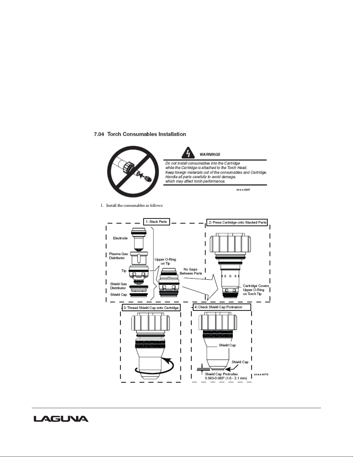
Installing consumable parts
The XT torch is a precision instrument. Take care when installing consumable parts to keep the parts clean and
free from any contamination that might cause a gas or coolant leak inside the consumable parts cartridge.
Assembly Sequence, 30-150 Amp Consumables
76
Page 77

77
Page 78
Consumable Parts Life
Tips and electrodes wear under normal usage. Tips and electrodes should be changed before failure to avoid
damaging the other consumable parts or the material to be cut. Optimum life will vary according to specific
cutting conditions. Keep a count of cuts per set of tip and electrode in a given application to establish the most
effective time to change consumable parts sets. The pilot arc is more erosive to the tip and electrode than the
cutting arc is, so an application that demands more pilot and pierce sequences will erode consumable parts
faster than an application that uses longer cuts but fewer arc starts.
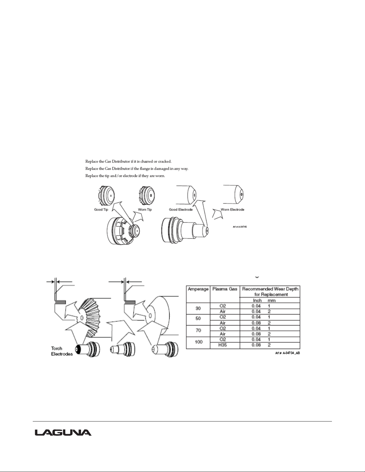
Tip – Tips wear as the arc erodes the tip orifice. When the tip is no longer round or has become enlarged, it
should be replaced. Tip life is best when cuts are made at optimum speed. Cutting too fast or too slow causes
the arc to bend and biases erosion, resulting in an orifice that is oval shaped.
Electrodes – The electrode wears from the hafnium or tungsten insert at the end of the electrode. The face of
the insert is liquefied by the heat of the arc and droplets erode from the insert as cutting progresses. Proper gas
flow will support longer electrode life. An electrode should be replaced when the electrode insert is pitted to a
depth of 1/16 inch (see chart below).
78
Page 79

Cut characteristics
Cut Surface – Cut surface is influenced by process and positioner precision more than by other parameters. For
smoothest cut face on different materials, use: mild steel – oxygen plasma
stainless < ¾’ – nitrogen / WMS
> ¾” – H35 / nitrogen
aluminum < ¾”– nitrogen / MS
> ¾” – H35 /nitrogen
Direction of cut – The plasma has a clockwise swirl as it exits the torch tip. Considering the direction of torch
travel, the right side of the cut will always show less bevel and top edge rounding than the left side. Program
cuts so that the right side will be on the finished part and the left side will be scrap.
Top edge rounding – Caused by the heat of the plasma arc at the top surface of the cut. Proper torch height
control can minimize or eliminate top edge rounding. Excessive top edge rounding is often a sign that torch
cutting height should be lower.
Top spatter – Top spatter is caused by fast cutting or by too high a torch height setting. Reducing cut speed or
lowering torch cutting height will reduce top spatter. Top spatter is easy to remove.
Bottom dross – Molten metal may build up on the bottom of the plate. Faster cut speeds reduce bottom dross as
less material is melted. Bottom dross that is easy to remove is an indication of slow cutting speed. Bottom
dross that is difficult to remove or requires grinding is an indication of too fast cut speed.
Kerf – Kerf width is specified in the cut charts and can be calculated into cut programs. The kerf width is related
to tip orifice size and higher current cutting will produce a wider kerf. Higher torch height will also result in a
wider kerf.
Bevel angle – Precision cut processes produce bevel angle in the 0-3° range. Conventional plasma cutting will
produce larger bevel angles. Proper torch height control will produce the smallest bevel angle, as well as
improved kerf width and minimal top edge rounding. A slower cut speed can be used when cutting circles and
corners to reduce bevel.
79
Page 80

Effect of Height Control Settings – General Purpose Cut
Nitride contamination – Air plasma cutting will produce nitride contamination of the cut face on carbon steel and
stainless steel. Nitride contaminated surfaces will require grinding before welding to eliminate weld porosity.
The depth of the contamination will be close to the Heat Affected Zone, between .005 and .010” in depth.
Nitride contamination can be eliminated by using a process other than air plasma; oxygen plasma for
carbon steel, H35 or nitrogen/WMS for non-ferrous materials.
Cut speed – Cut charts specify a cut speed that will produce high quality cut performance. Any plasma system
can cut at faster or slower speeds, but cut performance will be affected. Cut speed should be reduced for
corners and tight curves to reduce bevel and corner rounding.
Optimum cut speeds produce a trailing arc which will be visible in the slight arc lines visible in the cut
face. Arc lines are useful for evaluating cut speed on mild steel, but less so for aluminum and stainless steel.
Arc lines that trail at less than 15° indicate that cut speed is in the optimum range when air or oxygen plasma
processes are used. Optimum cut quality in precision cutting processes will result in arc lines that are near
vertical. A slow cut speed may show arc lines that angle forward and a fast cut speed will show arc lines at a
sharper angle relative to the top of the plate.
80
Page 81

Aluminum
Cut speed too fast
Cut drag lines are more than 15 degrees trailing the torch (torch movement right to left)
High speed bottom dross, easy to remove
Cut speed correct
Cut drag lines trail are visible, but cut surface is smooth
No dross
Cut speed too slow
Cut drag lines are more pronounced and cut surface is rougher
81
Page 82

Stainless Steel (H35 plasma)
Cut speed too fast
Gold heat discoloration swept in both directions
Cut drag lines more than 15 degrees trailing
High speed bottom dross, hard to remove
Cut Speed correct
Smooth cut surface
No dross
Cut Speed too slow
Heat discoloration is concentrated in the bottom half of the cut
Hard bottom dross, hard to remove
82
Page 83

Mild Steel (O2 plasma)
Cut Speed Too Fast
Trailing cut drag lines
Light bottom dross, hard to remove, some top spatter
Cut Speed Correct
Cut drag lines near vertical
No dross
Cut Speed Too Slow
Cut drag lines lead the torch
Heavy bottom dross, easy to remove
83
Page 84

Mild Steel (Air plasma)
Cut Speed Too Fast
Cut drag lines curve and trail torch movement
High speed bottom dross, hard to remove
Cut Speed Correct
Cut drag lines near vertical
Minimal dross
Cut Speed Too Slow
Cut drag lines vertical or leading the torch head
Thicker bottom dross, easy to remove
84
Page 85

Pierce
Lead-in
Overcut
Corner
Lead-out
Piercing
Piercing causes the molten metal to form a puddle on top of the plate. On thicker plate, pierce height is
calculated to keep the torch away from the plate so that the molten metal does not adhere to the consumable
parts and shorten parts life. Hold pierce height as the cutting table starts movement to allow the torch to clear
the pierce puddle before moving to cut height. Using the Inova height controller, this is done using the Set
Pierce Time function on the edit screen.
Lead-in and lead-out
Lead-in and lead-out should be calculated to allow the torch to move to cut height before starting the final piece
contour of the cut and to move away from the final piece before beginning end of cut current ramp down.
Corners
The cutting arc normally trails the torch tip orifice. When the torch makes an abrupt change in direction this
trailing arc cannot change direction as quickly at the bottom of the cut as at the top of the cut. This results in
undercutting of sharp corners. 2 techniques can be used to minimize this effect.
1. Use cut-outs – Overcut past the corner of the shape, then return and cross over the cut line to achieve a
square corner. Triangular or looped overcuts are commonly used.
2. Use the CNC corner slowdown function to hold torch height as it enters and leaves the corner. As the
speed decreases, the arc voltage will increase, driving the torch down, so corner slowdown will lock out the
height controller during the corner cut, keeping the torch at the programmed height, regardless of arc voltage
variations.
85
Page 86

Pierce
Lead-in
Overrun
at end
of cut
Cutting Circles
Circle cutting demands precise motion control and circle cut quality will vary as the circle diameter approaches
the thickness of the plate. In general, a circle that is equal in diameter to the thickness of the plate being cut is
the minimum circle diameter possible. Cut quality will decrease markedly when the circle diameter is less than
1.5 times the thickness of the plate being cut.
For maximum circle cut quality:
1. Slow down cut speed. Smaller circles may require a cut speed that is 60-50% of the speed specified in
system cut charts. A slower cut speed will eliminate trailing arc and allow the arc to cut at closer to 0° of bevel.
2. Maintain constant cut height through the circle. This may require locking out the height controller. As
the cut speed slows, arc voltage increases and the height controller tends to drive the torch down, changing cut
bevel. Avoid torch height movement by locking out the height controller during the circle cut.
3. Start the cut in the center of the circle and use a 90° lead-in to the circle. When the positioner is in top
running condition, a 90° lead-in will produce less distortion at the circle initiation. A cutting table with backlash
may produce a better cut when a radial lead-in is used.
4. End the cut by overburning the circle cut line rather than by using a lead-out. Time the cut to end just as
the arc completes the circle. A lead out or too much of an overburn will cause the arc to cut more of the outside
of the circle and cause a distortion at the point where the circle cut is completed. Many CNC systems use and
advanced off feature to ramp down cutting current end of cut. Use of the advanced off feature will improve circle
cutting.
86
Page 87

N2/Water Mist Secondary®™
In this process, tap water is used instead of a shield gas. The water is vaporized as it passes through
the torch head and a portion of the molecules separate onto hydrogen and oxygen. This vapor protects the cut
surface from ambient air contamination and eliminates nitriding in the cut surface.
Cutting with the N2/WMS process is economically efficient and produces genuine precision cut quality
over a broad range of non-ferrous applications.
Considerations:
Water supply should be at least 55 psi.
Hard water will leave mineral deposits, just as it does in sinks and faucets. A standard water
softening filter will prevent mineral deposits that can interfere with water flow in the torch passages.
Ohmic sensing to establish initial torch height is ineffective when water is present. The ohmic clip
should be removed from the torch for N2/WMS cutting. The ohmic sensing system will sense the
level of any water on the plate rather than the true position of the plate.
Underwater Cutting
Cutting under water is used by some operators to capture smoke and reduce flash and noise. Cutting under
water is possible with Ultra-Cut and Auto-Cut systems.
Considerations:
Cutting under water will reduce cut capacity and speed by up to 30 %
The cooling effect of water on the bottom of the plate will facilitate formation of dross
Cutting aluminum under or over water releases hydrogen, which can explode
Cutting with N2/WMS process is not recommended
The water in the table will become contaminated with cut residue and can be a toxic waste
87
Page 88

Power Supply Status Codes
Auto-Cut and Ultra-Cut systems display system status codes that are useful for optimizing system
performance and for troubleshooting. The status code is displayed on the power supply front panel.
The Status Indicator flashes a 2 part code that indicates the status of the system. When the Status
Indicator is dark the system is ready to cut. It is normal for the Status Indicator to flash when the GCM mode
switch is placed in set mode. At system start up, the Status Indicator flashes a 2 part code to indicate the CCM
firmware version that is loaded into the system. This code appears only once at start up. During normal
operation the Status Indicator may flash a code indicating an error or a condition that should be corrected. Some
codes will cause the system to cease operation to prevent damage to the hardware. Other codes will not cause
the system to cease operation, but will continue until the condition which caused the code to initiate is changed.
Status codes appear in a 2 part sequence. The Status Indicator will flash a number of times to indicate
the first number in the code sequence, then pause for 1.2 seconds and flash the second number of the code.
After 4 seconds, the code sequence will repeat.
Example: The Status Indicator blinks 4 times, pauses, then blinks 3 times. This code
(4-3) indicates overheating coolant and will continue until the condition is corrected.
88
Page 89

Status Indicator Codes
89
Page 90

90
Page 91

91
Page 92

Catalog
Number
Description
Propylene Glycol /
Deionized Water Mix
Freeze Protection
7-3580
Extra-Cool™
25/75
10°F / -12°C
7-3581
Ultra-Cool™
50/50
-27°F / -33°C
7-3582
ExtremeCool™
Concentrate to be mixed
with De-I™ Water
-65°F / --51°C
7-3583
De-I Water™
32°F / 0°C
Scheduled Maintenance
Lubricate Torch Cartridge O-Rings
An O-ring replacement kit with both torch and cartridge rings is available, catalog number 9-9488.
Coolant
Torch coolant becomes conductive with use and eventually will cause a shorted torch condition. Torch
coolant should be replaced every six months. Also remove and clean the external coolant filter and the smaller
filter located near the flow sensor.
Torch coolant is available pre-mixed or as concentrate.
92
Page 93

Periodic Maintenance
Troubleshooting Torch Coolant Leaks
93
Page 94

Technical Service Contact Numbers
Thermal Dynamics Technical Service is available for telephone or e-mail support. Technicians
are available to assist with installation, application and repair issues.
Technical Service Toll Free – 1-800-PLASMA2 (752-7622)
Automation Technical Service – 1-888-832-3477
Automation Customer Care – 1-866-279-2628
General Customer Care – 1-800-PLASMA1 (752-7621)
E-mail - tdctech@thermadyne.com
www.thermal-dynamics.com
94
Page 95

2072 Alton Parkway. Irvine, CA 92606
Ph: 800.234.1976 | www.lagunatools.com
Laguna Tools is not responsible for errors or omissions.
Specifications subject to change. Machines may be shown with optional accessories.
© 2018, Laguna Tools, Inc. LAGUNA® and the LAGUNA Logo® are the
registered trademarks of Laguna Tools, Inc. All rights reserved.
 Loading...