

Page 1
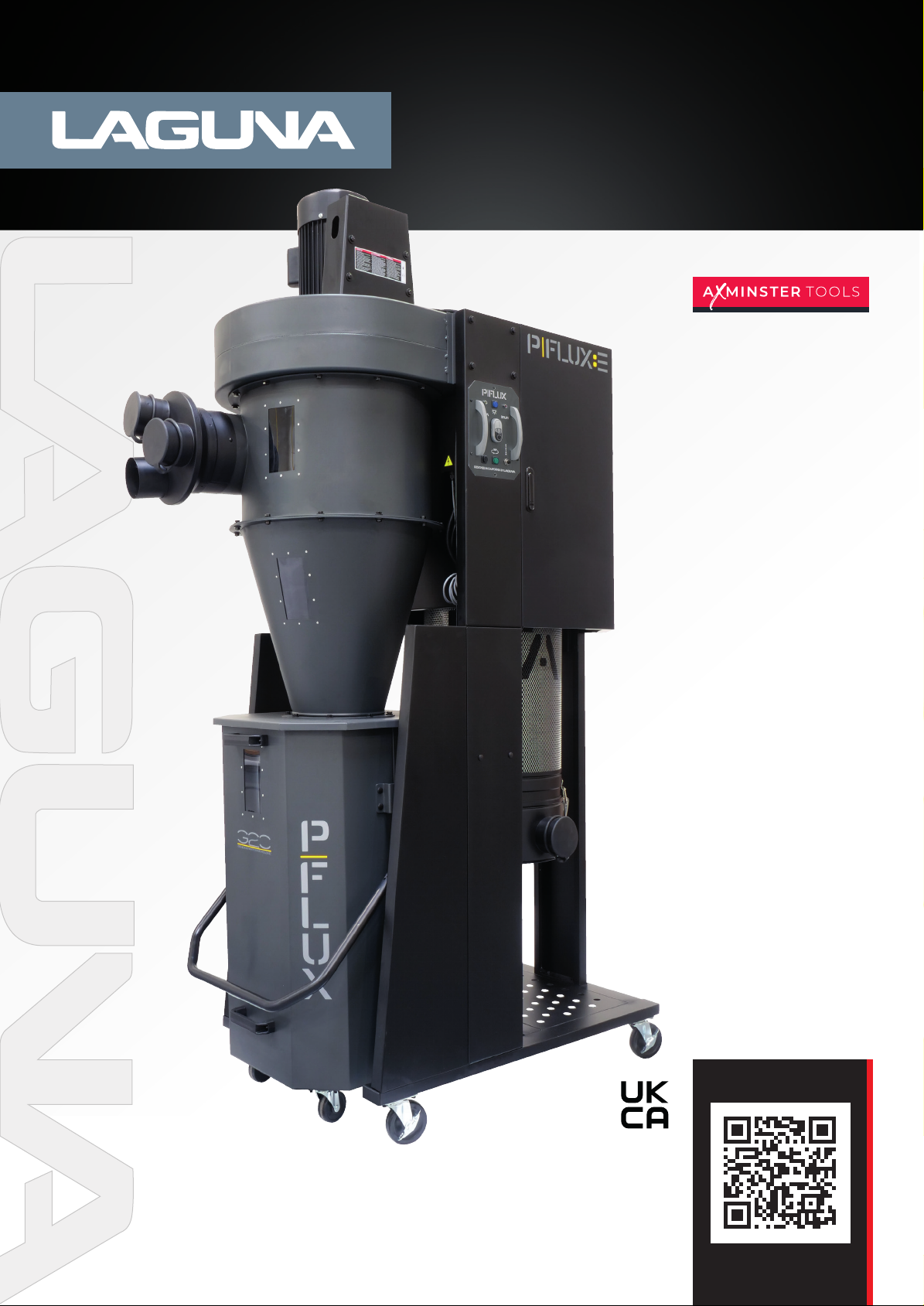
P|Flux 3 Cyclone
Extractor HEPA 230v
Code: 111771
Distributed by
N.B. Some pictures and diagrams in this manual may have buttons and electrical configurations
which differ slightly from the machine you purchased
Version: 3
Date: 1/10/25
DIGITAL MANUAL
DIGITAL MANUAL
Page 2

Contents
Safety 3
Important Safety Instructions 4
General Safety Rules 8
Wiring Diagrams 10
Power Connections 12
Power Supply 13
Programming Remote Control 15
Specifications 16
Unpacking 17
Assembly 18
Operation 32
Maintenance 33
HEPA Filter Replacement 35
Trouble Shooting 36
Parts Breakdown / Exploded Views 38
Parts List 43
Conformity Certificates 47
Warranty 49
Page 3

Mobile Dust Cyclone Manual
3
Warranty Registration
Register your machine at https://lagunatools.com/policies/warranty/
To prevent voiding this warranty, all products sold must be registered within thirty (30) days of receiving
the product. Registering the product will enable the original purchaser to receive notifications about
important product changes, receive customer service, and be able to file a warranty claim against defective
workmanship, parts, or materials.
SAFETY
READ AND UNDERSTAND THIS MANUAL AND ALL INSTRUCTIONS BEFORE USING THIS EQUIPMENT.
Failure to follow all instructions may result in electric shock, fire and/or serious personal injury or
property damage! Electronic copies of this manual are available at www.lagunatools.com.
SAFETY GUIDELINES - DEFINITIONS
This manual contains information that is important for you to know and understand. This
information relates to protecting YOUR SAFETY and PREVENTING EQUIPMENT PROBLEMS.
To help you recognize this information, we use the symbols below. Please read the manual
and pay attention to these sections.
Indicates an imminently hazardous situation which, if not avoided, will result in death or serious injury.
Indicates a potentially hazardous situation which, if not avoided, could result in death or serious injury.
Indicates a potentially hazardous situation which, if not avoided, may result in minor or moderate
injury.
Page 4
Mobile Dust Cyclone Manual
4
(Used without the safety alert symbol) indicates a potentially hazardous situation which, if not avoided,
may result in property damage.
Woodworking (and similar materials) can be dangerous if safe and proper operating procedures are
not followed. As with all machinery, there are certain hazards involved with the operation of the
machine. Using the machine with respect and caution will considerably lessen the possibility of
personal injury. However, if normal safety precautions are overlooked or ignored, personal injury to
the operator may result. Safety equipment such as guards, push sticks, hold-downs, featherboards,
goggles, dust masks and hearing protection can reduce the potential for injury. Even the best guard
will not make up for poor judgement, carelessness or inattention. Always use common sense and
exercise caution in the workshop. If a procedure feels dangerous, do not try it. Figure out an
alternative procedure that is safer. REMEMBER: Your personal safety is your responsibility.
IMPORTANT SAFETY INSTRUCTIONS
This machine was designed for certain applications only. We strongly recommend that this
machine not be modified and/or used for any application other than that for which it was
designed. If you have any questions relative to a particular application, DO NOT use the
machine until you have first contacted the manufacturer to determine if it can or should
be performed on the product.
If you have any questions relative to its application DO NOT use the product until you
have contacted the manufacturer and we have advised you.
When using an electrical appliance/machine, basic precautions should always be followed,
including the following:
READ ALL INSTRUCTIONS BEFORE USING (THIS APPLIANCE/MACHINE)
To reduce the risk of fire, electric shock, or injury:
1. Do not leave appliance when plugged in. Unplug from outlet when not in use and before
servicing.
2. Do not use outdoors or on wet surfaces
3. Do not allow to be used as a toy. Close attention is necessary when used by or near
children.
4. Use only as described in this manual. Use only manufacturer’s recommended
attachments.
5. Do not use with damaged cord or plug. If appliance is not working as it should, has
been dropped, damaged, left outdoors, or dropped into water, return it to a service center.
Page 5

5
6. Do not pull or carry by cord, use cord as a handle, close a door on cord, or pull cord
around sharp edges or corners. Do not run appliance over cord. Keep cord away from
heated surfaces.
7. Do not unplug by pulling on cord. To unplug, grasp the plug, not the cord.
8. Do not handle plug or appliance with wet hands.
9. Do not put any object into openings. Do not use with any opening blocked; keep free of
dust, lint, hair, and anything that may reduce air flow.
10. Keep hair, loose clothing, fingers, and all parts of body away from openings and
moving parts.
11. Turn off all controls before unplugging.
12. Use extra care when cleaning on stairs.
13. Do not use to pick up flammable or combustible liquids, such as gasoline, or use in
areas where they may be present.
14. Connect to a properly grounded outlet only. See Grounding Instructions.
SAVE THESE INSTRUCTIONS
1. Read and understand the warnings posted on the machine and in this manual.
Failure to comply with all of these warnings may cause serious injury.
2. Replace the warning labels if they become obscured or removed.
3. This Portable Cyclone Dust Collector is designed and intended for use by properly
trained and experienced personnel only. If you are not familiar with the proper and
safe operation of this type of dust collector, do not use until proper training and
knowledge have been obtained.
4. Do not use this machine for other than its intended use. If used for other purposes,
LAGUNA TOOLS INC., disclaims any real or implied warranty and holds itself
harmless from any injury that may result from that use.
5. Always wear approved safety glasses/face shields while using this machine.
6. Before operating this dust collector, remove tie, rings, watches and other jewelry,
and roll sleeves up past the elbows. Remove all loose clothing and confine long hair.
Non-slip footwear or anti-skid floor strips are recommended. Do not wear gloves.
7. Wear ear protectors (plugs or muffs) during extended periods of operation.
8. Some dust created by power sanding, sawing, grinding, drilling and other
construction activities contain chemicals known to cause cancer, birth defects or
other reproductive harm. Some examples of these chemicals are: (next page)
Mobile Dust Cyclone Manual
Page 6

6
• Lead from lead based paint.
• Crystalline silica from bricks, cement and other masonry products.
• Arsenic and chromium from chemically treated lumber.
Your risk of exposure varies, depending on how often you do this type of work. To
reduce your exposure to these chemicals, work in a well-ventilated area and work
with approved safety equipment, such as face or dust masks that are specifically
designed to filter out microscopic particles.
9. Do not operate this machine while tired or under the influence of drugs, alcohol or
any medication.
10.Make certain the switch is in the OFF position before connecting the machine to the
power source.
11.Make certain the machine is properly grounded.
12.Make all machine adjustments or maintenance with the machine unplugged from
the power source.
13.Form a habit of checking to see that all extra equipment such as adjusting keys,
wrenches, scrap, stock, and cleaning rags are removed away from the machine
before turning on.
14.Keep safety guards in place at all times when the machine is in use. If removed for
maintenance purposes, use extreme caution and replace the guards immediately
when maintenance is complete.
15.Make sure the dust collector is on a flat even surface and the wheels locked in place
before use.
16.Check damaged parts. Before further use of the machine, a guard or other part that
is damaged should be carefully checked to determine that it will operate properly
and perform its intended function. Check for alignment of moving parts, binding of
moving parts, breakage of parts, mounting and any other conditions that may
affect its operation. A guard or other part that is damaged should be properly
repaired or replaced.
17.Provide for adequate space surrounding work area and non-glare, overhead lighting.
18.Keep the floor around the machine clean and free of scrap material, oil and grease.
19.Keep visitors a safe distance from the work area. Keep children away.
Mobile Dust Cyclone Manual
Page 7

7
20.Make your workshop child proof with padlocks, master switches or by removing
starter keys.
21.Give your work undivided attention. Looking around, carrying on a conversation and
“horse-play” are careless acts that can result in serious injury.
.
22.Maintain a balanced stance at all times so that you do not fall or lean against the
dust collector. Do not overreach or use excessive force to perform any machine
operation.
23.Use the right tool at the correct speed and feed rate. Do not force a tool or
attachment to do a job for which it was not designed. The right tool will do the job
better and safer.
24.Use recommended accessories; improper accessories may be hazardous.
25.Maintain machinery with care. Follow instructions for lubricating and changing
accessories.
26.Turn off the machine before cleaning. Use a brush or compressed air to remove
dust or debris — do not use your hands.
27.Do not stand on the machine. Serious injury could occur if the machine tips over.
28.Never leave the machine running unattended. Turn the power off and do not leave
the machine until it comes to a complete stop.
29.Never operate or run the machine without closing the drum up against the lid.
Failure to do so will result in the machine amperage increasing and may trip your
circuit.
Familiarize yourself with the following safety notices used in this manual:
SAFETY GUIDELINES - DEFINITIONS
This manual contains information that is important for you to know and understand. This
information relates to protecting YOUR SAFETY and PREVENTING EQUIPMENT PROBLEMS.
To help you recognize this information, we use the symbols, described earlier. Please read
the manual and pay attention to these sections.
Mobile Dust Cyclone Manual
Page 8
Mobile Dust Cyclone Manual
8
GENERAL SAFETY RULES
FAILURE TO FOLLOW THESE RULES MAY RESULT IN SERIOUS INJURY.
FOR YOUR OWN SAFETY, READ AND UNDERSTAND THE INSTRUCTION MANUAL
BEFORE OPERATING THE MACHINE. Learn the unit’s application and limitations as well
as the specific hazards peculiar to it.
KEEP WORK AREA CLEAN. Cluttered areas and benches invite accidents.
DON’T USE IN DANGEROUS ENVIRONMENT. Don’t use this unit in damp or wet
locations, or expose it to rain. Keep work area well-lighted.
KEEP CHILDREN AND VISITORS AWAY. All children and visitors should be kept a safe
distance from work area.
DISCONNECT UNIT before servicing.
CHECK DAMAGED PARTS. Before further use of the unit, properly repair or replace any
part that is damaged.
FAILURE TO FOLLOW THESE RULES MAY RESULT IN SERIOUS INJURY.
ADDITIONAL SAFETY FOR DUST COLLECTORS
Intended use. This dust collector is only intended for collecting wood dust and chips from
woodworking machines. Do not use this dust collector to collect metal, dirt, pebbles,
drywall, asbestos, lead paint, silica, liquids, aerosols, or any flammable, combustible, or
hazardous materials. This dust collector is intended for commercial use.
Hazardous dust. Dust created while using machinery may cause cancer, birth defects, or
long-term respiratory damage. Be aware of dust hazards associated with each work piece
material, and always wear a NIOSH-approved respirator to reduce your risk.
Dust allergies. Dust from certain woods may cause an allergic reaction in people and
animals.
Make sure you know what type of wood dust you will be exposed to in case there is a
possibility of an allergic reaction.
Page 9

9
Wear respirator. Fine dust that is too small to be caught in the filter will be blown into
the ambient air during operation. Always wear a NIOSH-approved respirator during
operation and for a short time after to reduce your risk of permanent respiratory damage.
Emptying dust. When emptying dust from the collection container, wear a respirator and
safety glasses. Empty dust away from ignition sources and into an approved container.
Disconnecting power supply. Turn the switch off, disconnect the dust collector from the
power supply, and allow the impeller to come to a complete stop before leaving the
machine unattended or doing any service, cleaning, maintenance, or adjustments.
Suspended dust particles and ignition sources. Do not operate the dust collector in
areas were explosion risks are high. Areas of high risk include, but are not limited to,
areas near pilot lights, open flames, or other ignition sources.
Fire suppression. Only operate the dust collector in locations that contain a fire
suppression system or have a fire extinguisher nearby.
Impeller hazards. Do not place your hands or tools near the open inlet during operation
for any reason. The powerful suction could easily cause accidental contact with the
impeller, which will
cause serious personal injury or damage to the machine. Always keep small animals and
children away from open dust collection inlets.
Avoiding sparks. Do not allow steel or rocks to strike the impeller—this may produce
sparks.
Sparks can smolder in wood dust for a long time before a fire is detected. If you
accidentally cut
Into wood containing tramp metal (nails, staples, spikes, etc.), immediately turn off the
dust collector, disconnect it from power, and wait for the impeller to stop—then empty the
collection container into an approved airtight metal container.
Operating location. To reduce respiratory exposure to fine dust, locate permanently
installed dust collectors away from the working area, or in another room that is equipped
with a smoke detector. Do not operate the dust collector in rainy or wet locations—
exposure to water may create a shock hazard or decrease the life of the machine.
Static electricity. Plastic dust lines generate high amounts of static electricity as dust
chips pass through them. Although rare, sparks caused by static electricity can cause
explosions or fire. To reduce this risk, make sure all dust lines are thoroughly grounded by
using a grounding wire.
Regular cleaning. Regularly check/empty the collection bags or drum to avoid the
buildup of fine dust that can increase the risk of fire. Make sure to regularly clean the
surrounding area where the machine is operated—excessive dust buildup on overhead
lights, heaters, electrical panels, or other heat sources will increase the risk of fire.
Mobile Dust Cyclone Manual
Page 10
10
SAVE THESE INSTRUCTIONS.
230V
Refer to them often and use them to instruct others.
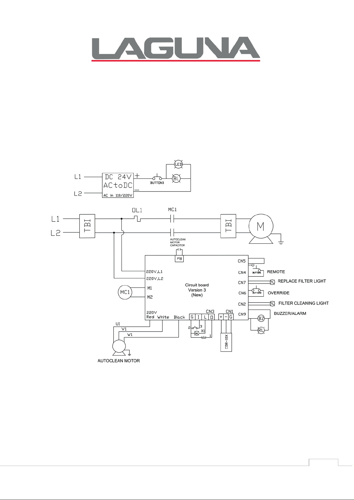
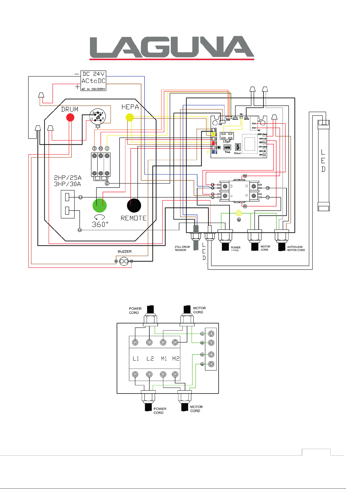
WIRING DIAGRAMS
POWER CONNECTIONS
Figure 1: Power Connections & Wiring
Mobile Dust Cyclone Manual
Page 11
11
CONTROL PANEL
Figure 1A: Control Panel
SECONDARY JUNCTION BOX
Figure 2: Internal Wiring
Mobile Dust Cyclone Manual
Page 12
Mobile Dust Cyclone Manual
12
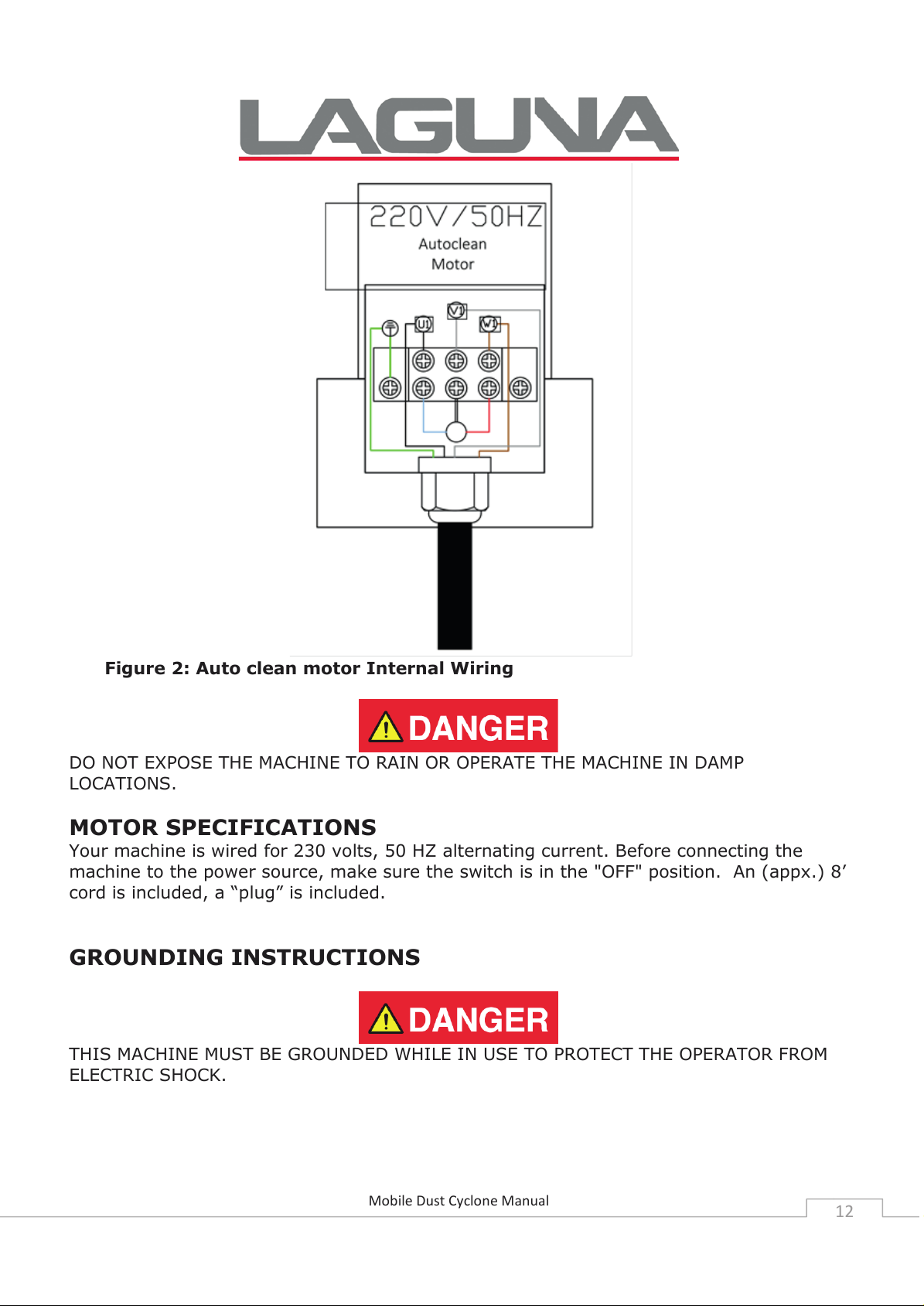
Figure 2: Auto clean motor Internal Wiring
DO NOT EXPOSE THE MACHINE TO RAIN OR OPERATE THE MACHINE IN DAMP
LOCATIONS.
MOTOR SPECIFICATIONS
Your machine is wired for 230 volts, 50 HZ alternating current. Before connecting the
machine to the power source, make sure the switch is in the "OFF" position. An (appx.) 8’
cord is included, a “plug” is included.
GROUNDING INSTRUCTIONS
THIS MACHINE MUST BE GROUNDED WHILE IN USE TO PROTECT THE OPERATOR FROM
ELECTRIC SHOCK.
Page 13

13
1. This appliance must be connected to a grounded metal, permanent wiring system; or
an equipment-grounding conductor must be run with the circuit conductors and connected
to the equipment-grounding terminal or lead on the appliance.
The installer, such as a qualified electrician, cut (or bend over) and insulate the grounding
conductor from a field wiring supply cable.
In the event of certain types of malfunctions or breakdowns, grounding provides a path of
least resistance for electric current—in order to reduce the risk of electric shock.
Improper connection of the equipment-grounding wire can result in a risk of electric shock.
The wire with green insulation (with or without yellow stripes) is the equipment-grounding
wire. If repair or replacement of the power cord or plug is necessary, do not connect the
equipment-grounding wire to a live (current carrying) terminal.
Check with a qualified electrician or service personnel if you do not understand these
grounding requirements, or if you are in doubt about whether the tool is properly
grounded. If you ever notice that a cord or plug is damaged or worn, disconnect it from
power, and immediately replace it with a new one.
Full Loadamperage Draw
PFLUX3 (3HP/230V/50HZ/Single phase) Amp
draw
at 230V
...................
17 Am
ps
Power Supply Circuit Requirements
The
power sourcecircuit
amperage
one of higher
compliance
area or you plan to connect your machine to a shared circuit, consult a qualified
electrician.
PFLUX3 (3HP/230V/50HZ/Single phase)
given
with wiring
below.
amperage without
for
yourmachi
Never replace
consulting
codes.
If you are unsure about the wiring codes in your
ne must
a circuit
a qualified
Circui
be grounded and rated for the
breaker
t Size (
on an
electrician
230V)
exist
ing circuit with
to
ensure
.........30Amp
s
minimum
IN ALL CASES, MAKE CERTAIN THE RECEPTACLE IN QUESTION IS PROPERLY GROUNDED.
IF YOU ARE NOT SURE, HAVE A QUALIFIED ELECTRICIAN CHECK THE RECEPTACLE.
230 VOLT Single-Phase Operation
The motor supplied with your machine is a 30 Volt motor. It is shipped ready-to-run for
230 Volt operation. An (appx.) 8’ cord is included; a “plug” is included.
Mobile Dust Cyclone Manual
Page 14
14
OFF button
ON button
*Remote set button
*Used to match up a new hand held
control with the remote switch
CLEAN button
ON/OFF Switch
Receiver SET button
Full drum detection
*includes sound alert.
HEPA Filter detection
On board circuit breaker
Override
ON/OFF button to
illuminate drum
Requires a 12V, type 27A alkaline battery.
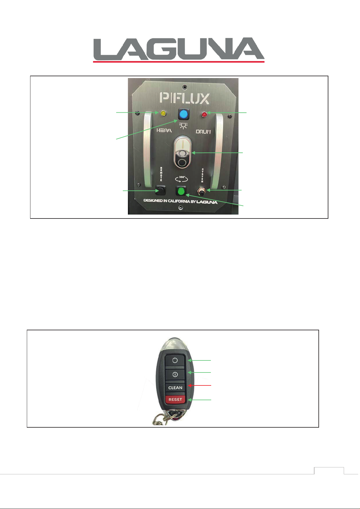
FUNCTION
Figure 3: High Frequency Remote Control Receiver and Manual Switch
HEPA Filter detection – will illuminate when filter cleans (automatic cleaning/override)
Full drum detection – when drum is full, buzzer* will constantly sound off and light will illuminate.
*When the drum is close to 70%-80% full; intermittent buzzing will occur; this is a normal state.
ON/OFF Switch – turns cyclone ON or OFF.
On board circuit breaker – Pops out if machine overloads. Press to reset.
Override – Press for (3) seconds to activate override cleaning while the cyclone is ON. You can also
activate this function by pressing the CLEAN button on the hand held remote for (3) seconds.
Receiver SET button – Used to program receiver.
ON/OFF Illuminate drum – controls the LED light on the drum lid to illuminate inside the drum for
visuals of the dust level. .
Figure 4: Hand Held Remote
Mobile Dust Cyclone Manual
Page 15
15
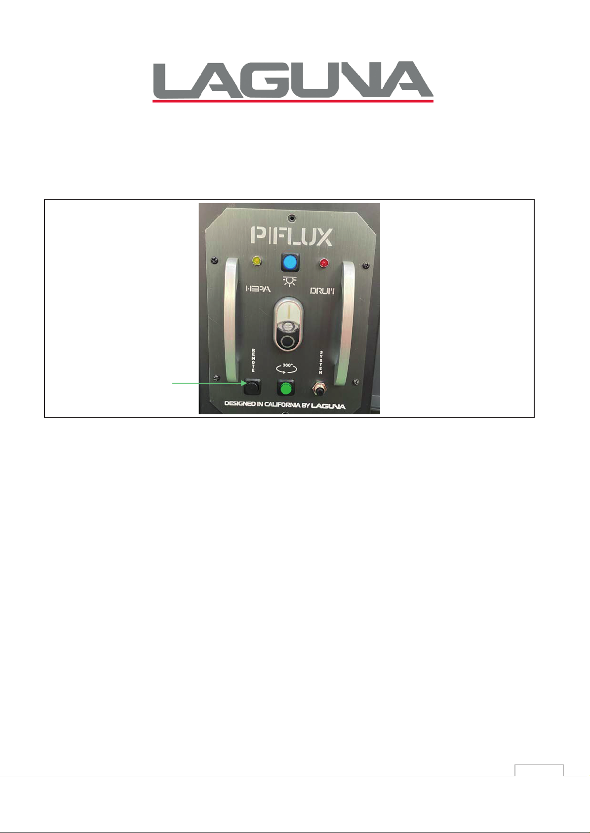
Receiver set button
PROGRAMMING THE REMOTE CONTROL
1. Ensure the machine is switch ON before programming the remote control.
2. Press the black set button on the bottom of the remote switch until you hear two beeps.
3. Press the Remote set button on your hand held controller simultaneously with the
black button until you hear three beeps to complete the set up.
Figure 5: Receiver Set Button
MULTIPLE HAND HELD REMOTE SETUP
You can pair up to five (MAX) hand held remotes; however each hand held remote needs
to be setup individually following the programming steps above.
If you setup a sixth hand held remote, it will override the first hand held remote. If a
seventh hand held remote is setup, it will override the second hand held remote. And so
on.
Mobile Dust Cyclone Manual
Page 16
Mobile Dust Cyclone Manual
16
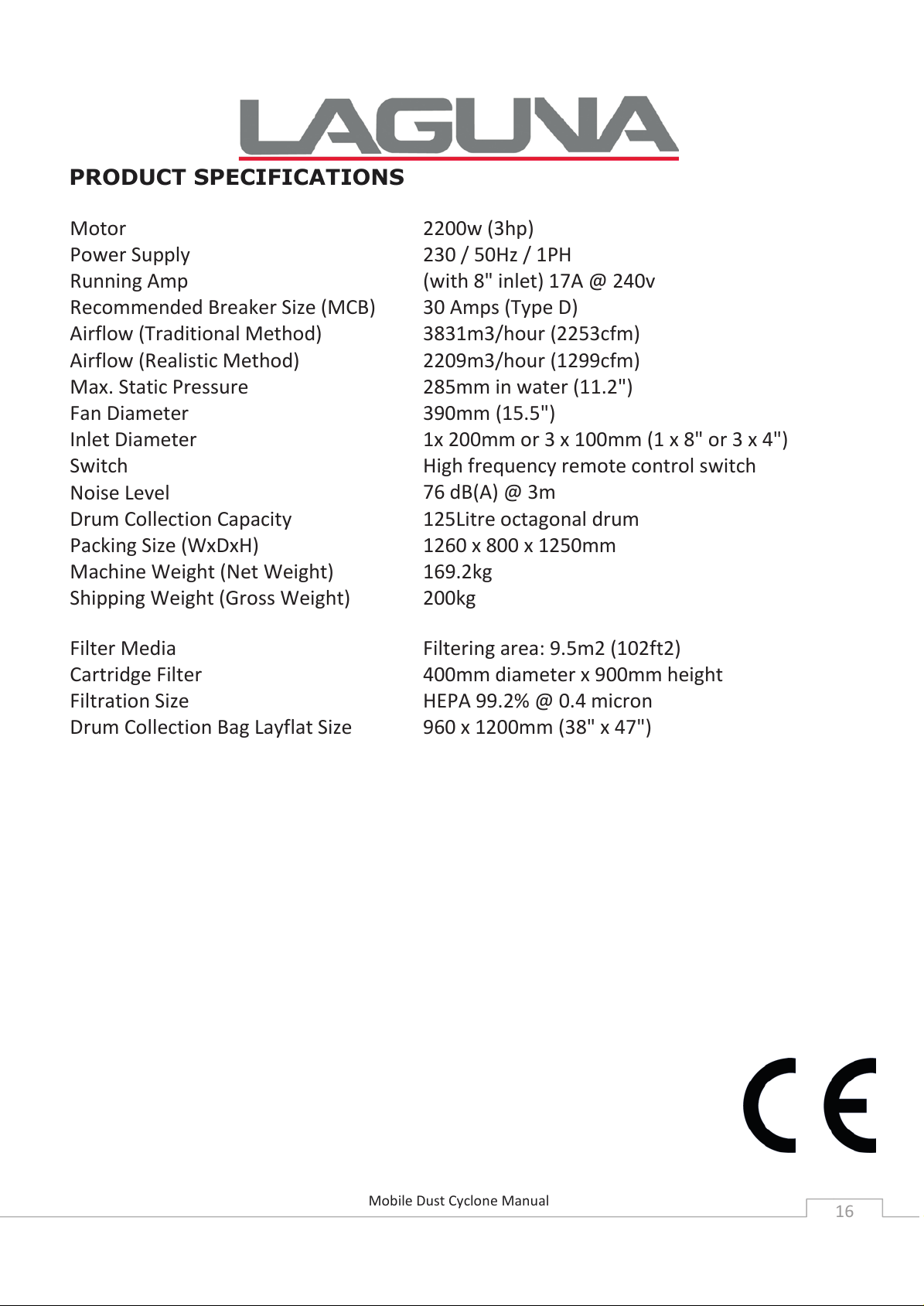
PRODUCT SPECIFICATIONS
Motor
Power Supply
Running Amp
Recommended Breaker Size (MCB)
Airflow (Traditional Method)
Airflow (Realistic Method)
Max. Static Pressure
Fan Diameter
Inlet Diameter
Switch
Noise Level
Drum Collection Capacity
Packing Size (WxDxH)
Machine Weight (Net Weight)
Shipping Weight (Gross Weight)
Filter Media
Cartridge Filter
Filtration Size
Drum Collection Bag Layflat Size
2200w (3hp)
230 / 50Hz / 1PH
(with 8" inlet) 17A @ 240v
30 Amps (Type D)
3831m3/hour (2253cfm)
2209m3/hour (1299cfm)
285mm in water (11.2")
390mm (15.5")
1x 200mm or 3 x 100mm (1 x 8" or 3 x 4")
High frequency remote control switch
76 dB(A) @ 3m
125Litre octagonal drum
1260 x 800 x 1250mm
169.2kg
200kg
Filtering area: 9.5m2 (102ft2)
400mm diameter x 900mm height
HEPA 99.2% @ 0.4 micron
960 x 1200mm (38" x 47")
Page 17
Mobile Dust Cyclone Manual
17
UNPACKING
Your Mobile Dust Cyclone comes packed in a single box. Before attempting to assemble
this machine, follow these directions for unpacking:
1. Carefully cut the banding straps and remove them from the box.
2. Cut along the tape line at the top of the box.
3. Remove all parts from the top of the styrofoam and set aside.
4. Remove the styrofoam packing material from the top of the machine and set aside for
further use, during assembly.
5. Cut the cardboard box (top to bottom) in the four corners for easy removal of the box.
6. Carefully take out the machine components from the box and set aside.
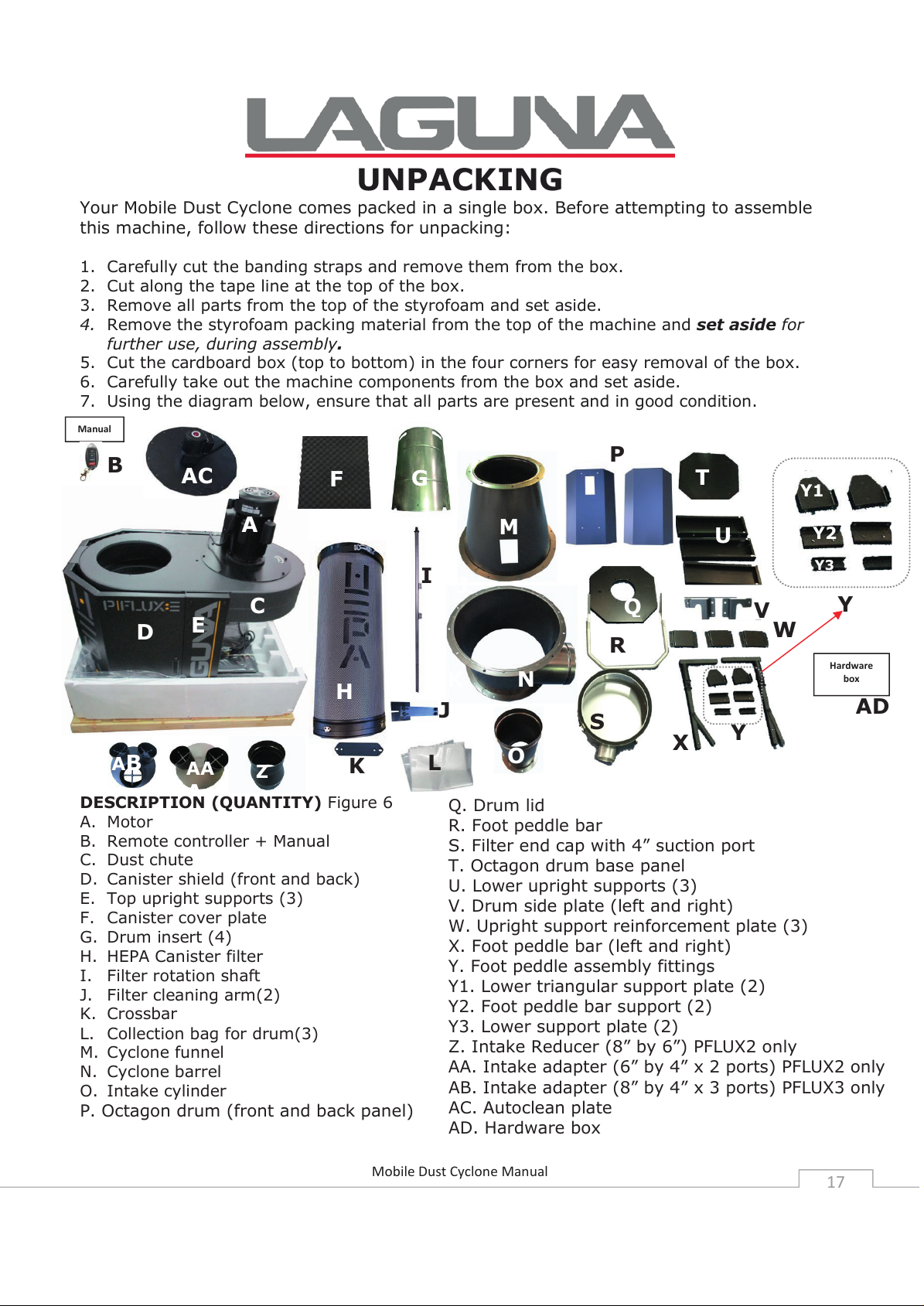
7. Using the diagram below, ensure that all parts are present and in good condition.
DESCRIPTION (QUANTITY) Figure 6
A. Motor
B. Remote controller + Manual
C. Dust chute
D. Canister shield (front and back)
E. Top upright supports (3)
F. Canister cover plate
G. Drum insert (4)
H. HEPA Canister filter
I. Filter rotation shaft
J. Filter cleaning arm(2)
K. Crossbar
L. Collection bag for drum(3)
M. Cyclone funnel
N. Cyclone barrel
O. Intake cylinder
P. Octagon drum (front and back panel)
G
J
KMN
Q
R
S
U
W
X
Y
Y
Y1
Y2
Y3
Hardware
box
Manual
Q. Drum lid
R. Foot peddle bar
S. Filter end cap with 4” suction port
T. Octagon drum base panel
U. Lower upright supports (3)
V. Drum side plate (left and right)
W. Upright support reinforcement plate (3)
X. Foot peddle bar (left and right)
Y. Foot peddle assembly fittings
Y1. Lower triangular support plate (2)
Y2. Foot peddle bar support (2)
Y3. Lower support plate (2)
Z. Intake Reducer (8” by 6”) PFLUX2 only
AA. Intake adapter (6” by 4” x 2 ports) PFLUX2 only
AB. Intake adapter (8” by 4” x 3 ports) PFLUX3 only
AC. Autoclean plate
AD. Hardware box
AD
A
B
C
D
E
H
O
K
AA
AB
Z
F
A
C
D
E
G
AC
I
J
L
K
P
T
V
Page 18
Mobile Dust Cyclone Manual
18
Report any missing or damaged parts to your dealer or distributor. Prior to tool
assembly and use, read this manual thoroughly to familiarize yourself with proper
assembly, maintenance and safety procedures.
ASSEMBLY
This step requires two adults. This Mobile Dust Cyclone is heavy, be
careful when lifting and handling it! Failure to comply may cause serious
injury and/or damage to the machine and/or property!
Tools/items Required:
10mm wrench / 12mm wrench / 14mm wrench
Phillips screwdriver
4mm hex wrench / 5mm hex wrench
Plug for cord, 3 wire
Silicone (1 tube, clear)
Caulk gun (for silicone)
To assemble your dust cyclone, follow these steps:
For your own safety, do not connect the machine to the power source until the machine is
completely assembled. Please also make sure that you read and understand the entire
instruction manual.
ASSEMBLY TIME ESTIMATE 5 to 6 hours
Visit the Laguna Tools Video page for setup assistance.
Page 19
Mobile Dust Cyclone Manual
19
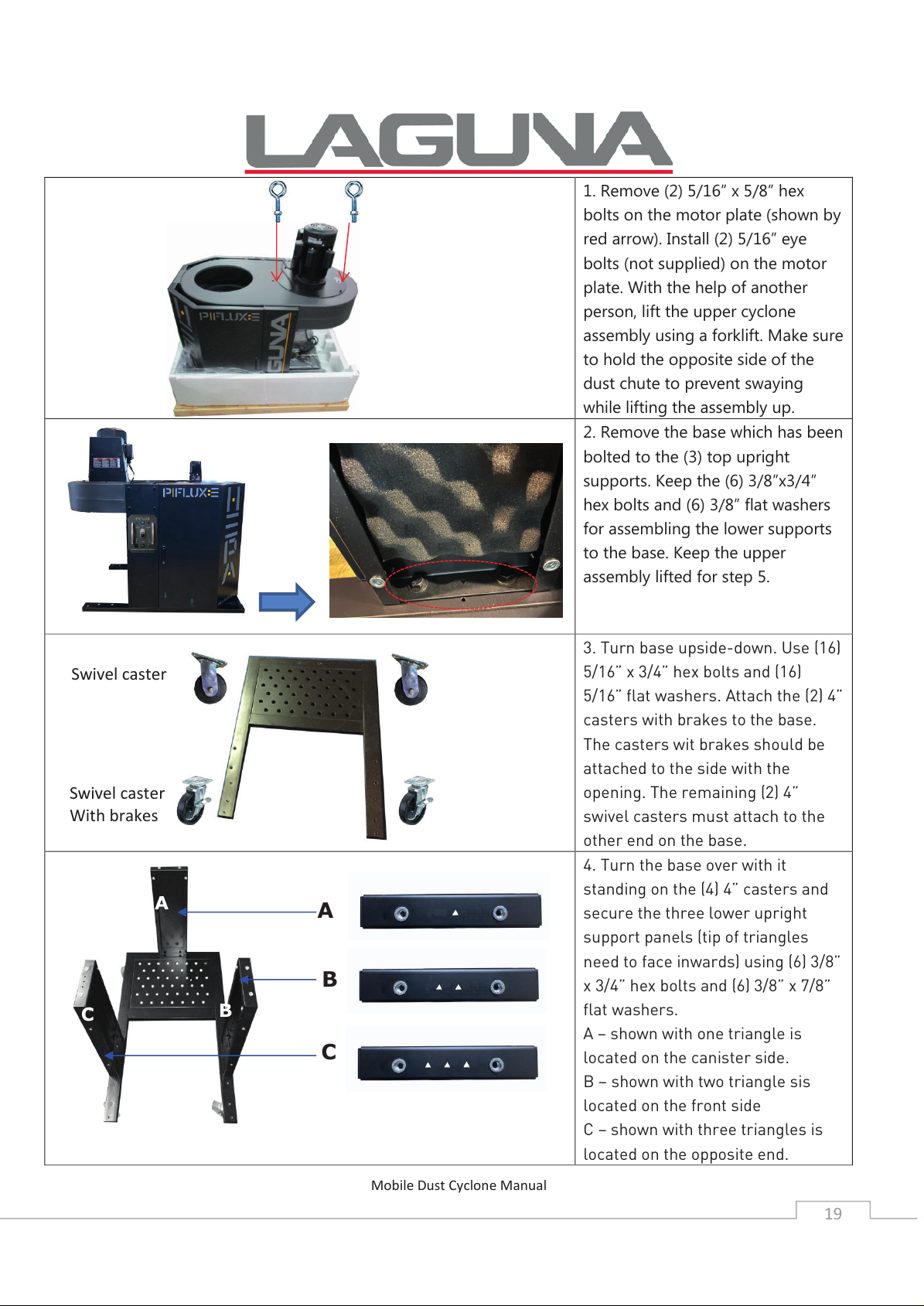
1. Remove (2) 5/16” x 5/8” hex
bolts on the motor plate (shown by
red arrow). Install (2) 5/16” eye
bolts (not supplied) on the motor
plate. With the help of another
person, lift the upper cyclone
assembly using a forklift. Make sure
to hold the opposite side of the
dust chute to prevent swaying
while lifting the assembly up.
2. Remove the base which has been
bolted to the (3) top upright
supports. Keep the (6) 3/8”x3/4”
hex bolts and (6) 3/8” flat washers
for assembling the lower supports
to the base. Keep the upper
assembly lifted for step 5.
3. Turn base upside-down. Use (16)
5/16” x 3/4” hex bolts and (16)
5/16” flat washers. Attach the (2) 4”
casters with brakes to the base.
The casters wit brakes should be
attached to the side with the
opening. The remaining (2) 4”
swivel casters must attach to the
other end on the base.
4. Turn the base over with it
standing on the (4) 4” casters and
secure the three lower upright
support panels (tip of triangles
need to face inwards) using (6) 3/8”
x 3/4” hex bolts and (6) 3/8” x 7/8”
flat washers.
A – shown with one triangle is
located on the canister side.
B – shown with two triangle sis
located on the front side
C – shown with three triangles is
located on the opposite end.
Swivel caster
Swivel caster
With brakes
ABC
A
B
C
Page 20
Mobile Dust Cyclone Manual
20
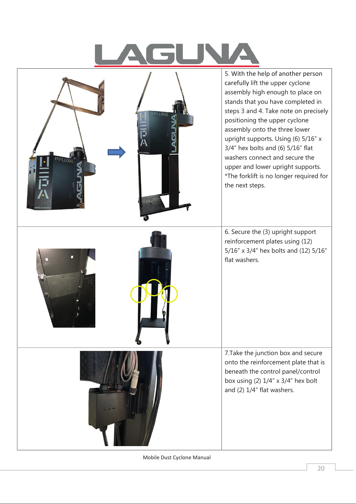
5. With the help of another person
carefully
lift the upper cyclone
assembly high enough to place on
stands that you have completed in
steps 3 and 4. Take note on precisely
positioning the upper cyclone
assembly onto the three lower
upright supports. Using (6) 5/16” x
3/4” hex bolts and (6) 5/16” flat
washers connect and secure the
upper and lower upright supports.
*The forklift is no longer required for
the next steps.
6. Secure the (3) upright support
reinforcement plates using (12)
5/16” x 3/4” hex bolts and (12) 5/16”
flat washers.
7.Take the junction box and secure
onto the reinforcement plate that is
beneath the control panel/control
box using (2) 1/4” x 3/4” hex bolt
and (2) 1/4” flat washers.
Page 21
Mobile Dust Cyclone Manual
21
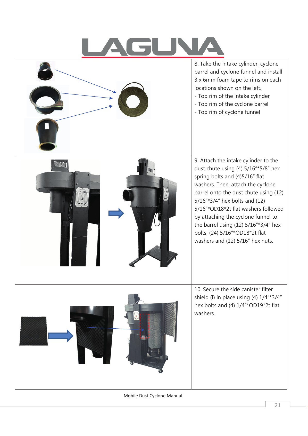
8. Take the intake cylinder, cyclone
barrel and cyclone funnel and install
3 x 6mm foam tape to rims on each
locations shown on the left.
- Top rim of the intake cylinder
- Top rim of the cyclone barrel
- Top rim of cyclone funnel
9. Attach the intake cylinder to the
dust chute using (4) 5/16”*5/8” hex
spring bolts and (4)5/16” flat
washers. Then, attach the cyclone
barrel onto the dust chute using (12)
5/16”*3/4” hex bolts and (12)
5/16”*OD18*2t flat washers followed
by attaching the cyclone funnel to
the barrel using (12) 5/16”*3/4” hex
bolts, (24) 5/16”*OD18*2t flat
washers and (12) 5/16” hex nuts.
10. Secure the side canister filter
shield (I) in place using (4) 1/4”*3/4”
hex bolts and (4) 1/4”*OD19*2t flat
washers.
Page 22
Mobile Dust Cyclone Manual
22
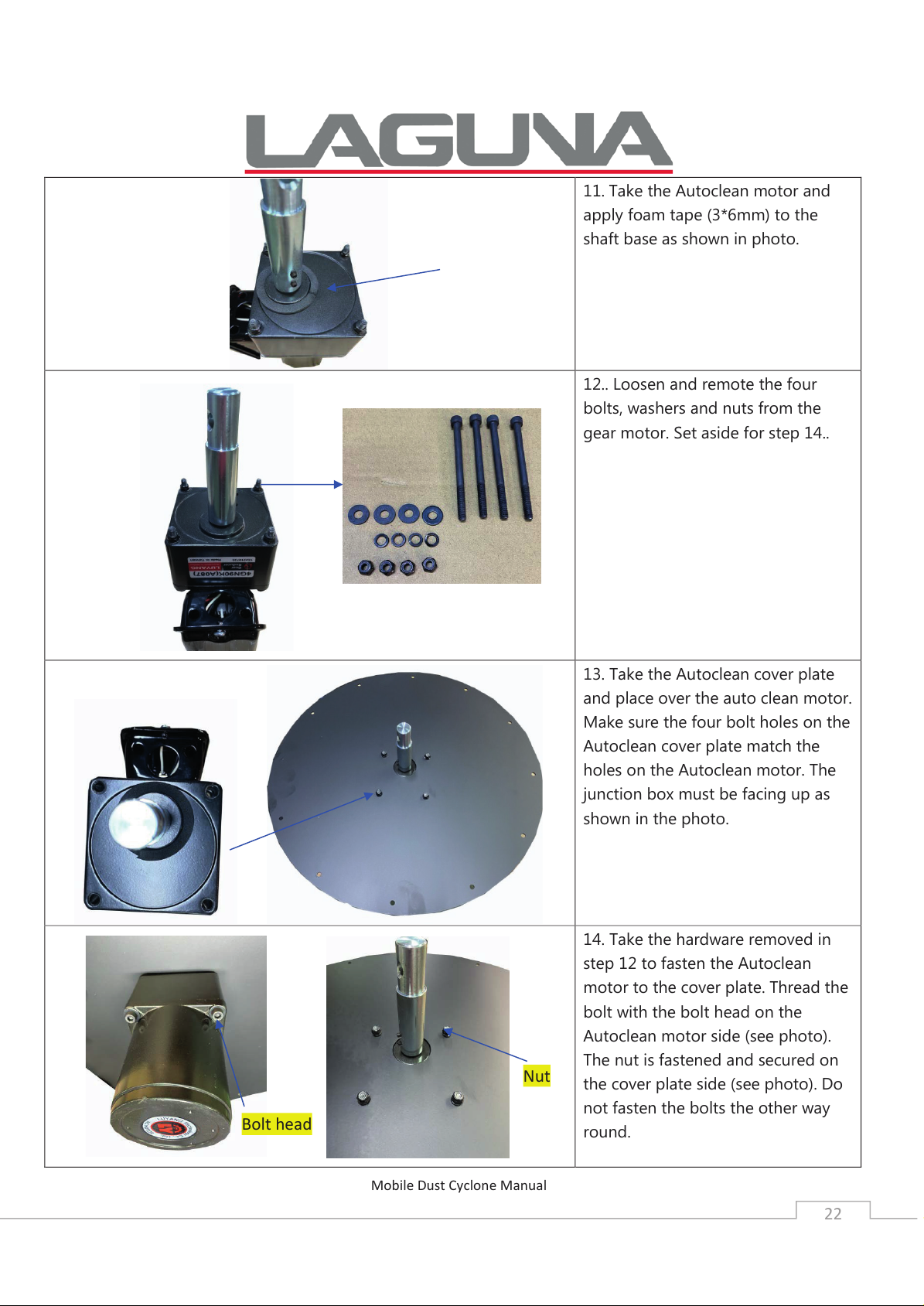
11. Take the Autoclean motor and
apply foam tape (3*6mm) to the
shaft base as shown in photo.
12.. Loosen and remote the four
bolts, washers and nuts from the
gear motor. Set aside for step 14..
13. Take the Autoclean cover plate
and place over the auto clean motor.
Make sure the four bolt holes on the
Autoclean cover plate match the
holes on the Autoclean motor. The
junction box must be facing up as
shown in the photo.
14. Take the hardware removed in
step 12 to fasten the Autoclean
motor to the cover plate. Thread the
bolt with the bolt head on the
Autoclean motor side (see photo).
The nut is fastened and secured on
the cover plate side (see photo). Do
not fasten the bolts the other way
round.
Bolt head
Nut
Page 23
Mobile Dust Cyclone Manual
23
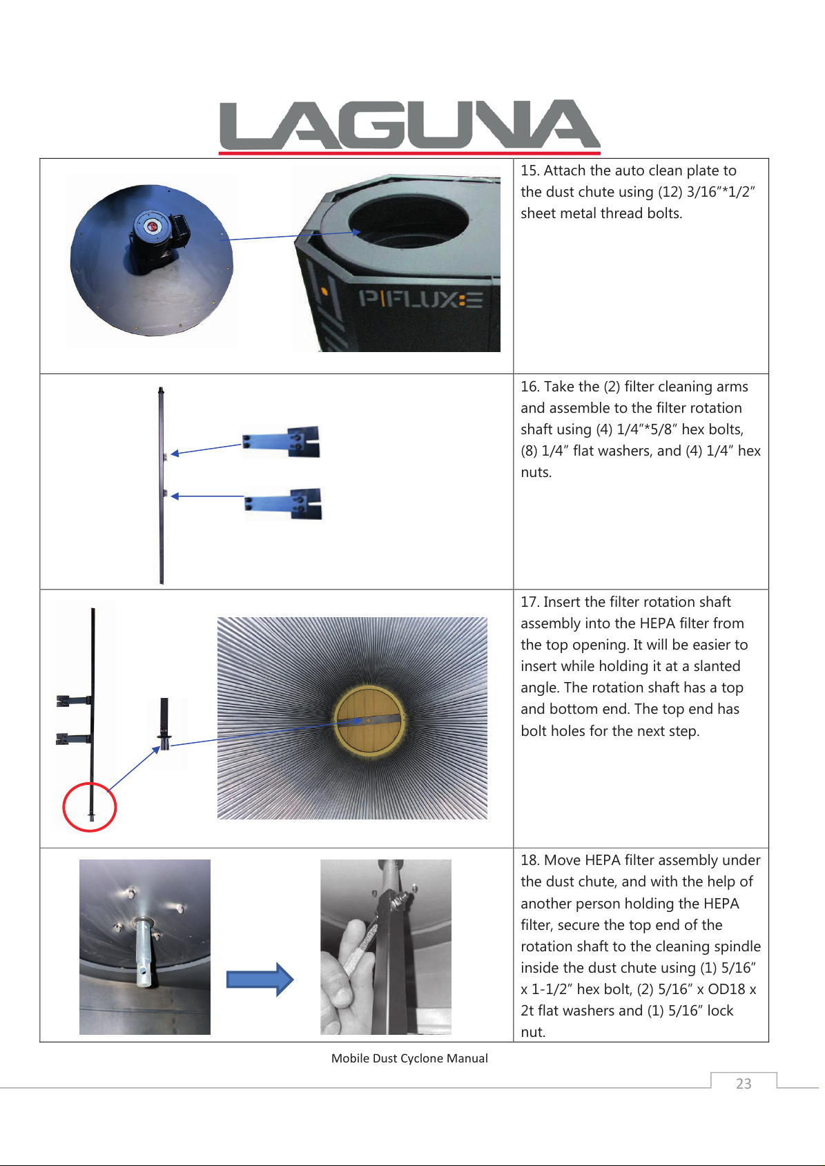
15. Attach the auto clean plate to
the dust chute using (12) 3/16”*1/2”
sheet metal thread bolts.
16. Take the (2) filter cleaning arms
and assemble to
the filter rotation
shaft using (4) 1/4”*5/8” hex bolts,
(8) 1/4” flat washers, and (4) 1/4” hex
nuts.
17. Insert the filter rotation shaft
assembly into the HEPA filter from
the top opening. It will be easier to
insert while holding it at a slanted
angle. The rotation shaft has a top
and bottom end. The top end has
bolt holes for the next step.
18. Move HEPA filter assembly under
the dust chute, and with the help of
another person holding the HEPA
filter, secure the top end of the
rotation shaft to the cleaning spindle
inside the dust chute using (1) 5/16”
x 1-1/2” hex bolt, (2) 5/16” x OD18 x
2t flat washers and (1) 5/16” lock
nut.
Page 24
Mobile Dust Cyclone Manual
24
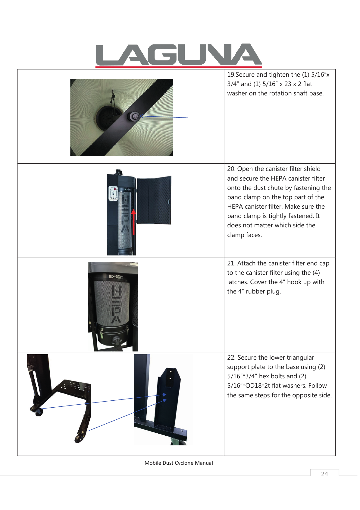
19.Secure and tighten the (1) 5/16”x
3/4” and (1) 5/16” x 23 x 2 flat
washer on the rotation shaft base.
20. Open the canister filter shield
and secure the HEPA canister filter
onto the dust chute by fastening the
band clamp on the top part of the
HEPA canister filter. Make sure the
band clamp is tightly fastened. It
does not matter which side the
clamp faces.
21. Attach the canister filter end cap
to the canister filter using the (4)
latches. Cover the 4” hook up with
the 4” rubber plug.
22. Secure the lower triangular
support plate to the base using (2)
5/16”*3/4” hex bolts and (2)
5/16”*OD18*2t flat washers. Follow
the same steps for the opposite side.
Page 25
Mobile Dust Cyclone Manual
25
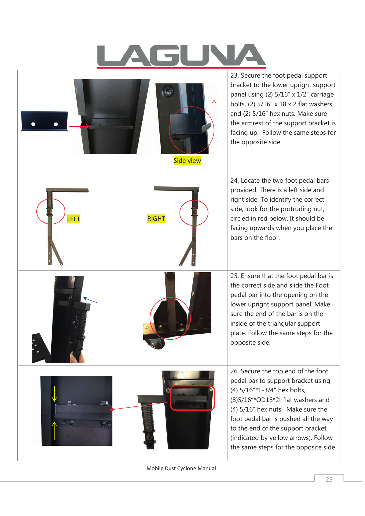
23. Secure the foot pedal support
bracket to the lower upright support
panel using (2) 5/16” x 1/2” carriage
bolts, (2) 5/16” x 18 x 2 flat washers
and (2) 5/16” hex nuts. Make sure
the armrest of the support bracket is
facing up. Follow the same steps for
the opposite side.
24. Locate the two foot pedal bars
provided. There is a left side and
right side. To identify the correct
side, look for the protruding nut,
circled in red below. It should be
facing upwards when you place the
bars on the floor.
25. Ensure that the foot pedal bar is
the correct side and slide the Foot
pedal bar into the opening on the
lower upright support panel. Make
sure the end of the bar is on the
inside of the triangular support
plate. Follow the same steps for the
opposite side.
26. Secure the top end of the foot
pedal bar to support bracket using
(4) 5/16”*1-3/4” hex bolts,
(8)5/16”*OD18*2t flat washers and
(4) 5/16” hex nuts. Make sure the
foot pedal bar is pushed all the way
to the end of the support bracket
(indicated by yellow arrows). Follow
the same steps for the opposite side.
LEFT
RIGHT
Side view
Page 26
Mobile Dust Cyclone Manual
26
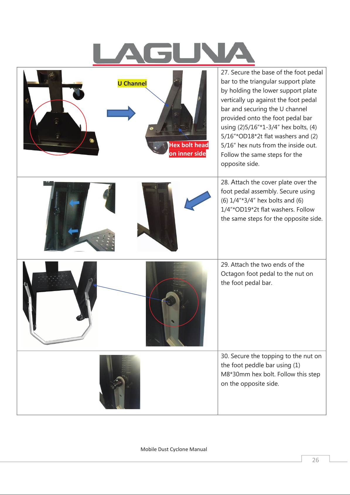
27. Secure the base of the foot pedal
bar to the triangular support plate
by holding the lower support plate
vertically up against the foot pedal
bar and securing the U channel
provided onto the foot pedal bar
using (2)5/16”*1-3/4” hex bolts, (4)
5/16”*OD18*2t flat washers and (2)
5/16” hex nuts from the inside out.
Follow the same steps for the
opposite side.
28. Attach the cover plate over the
foot pedal assembly. Secure using
(6) 1/4”*3/4” hex bolts and (6)
1/4”*OD19*2t flat washers. Follow
the same steps for the opposite side.
29. Attach the two ends of the
Octagon foot pedal to the nut on
the foot pedal bar.
30. Secure the topping to the nut on
the foot peddle bar using (1)
M8*30mm hex bolt. Follow this step
on the opposite side.
U Channel
Hex bolt head
on inner side
Page 27
Mobile Dust Cyclone Manual
27
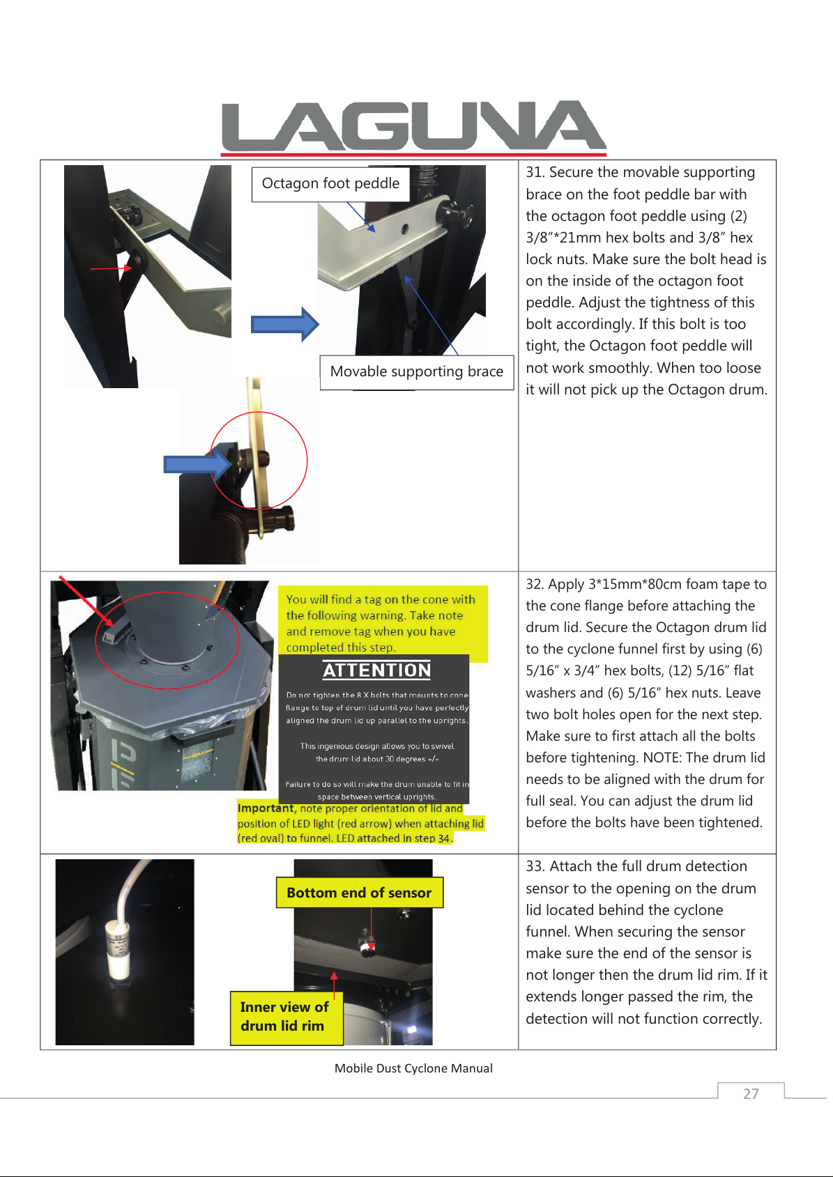
31. Secure the movable supporting
brace on the foot peddle bar with
the octagon foot peddle using (2)
3/8”*21mm hex bolts and 3/8” hex
lock nuts. Make sure the bolt head is
on the inside of the octagon foot
peddle. Adjust the tightness of this
bolt accordingly. If this bolt is too
tight, the Octagon foot peddle will
not work smoothly. When too loose
it will not pick up the Octagon drum.
32. Apply 3*15mm*80cm foam tape to
the cone flange before attaching the
drum lid. Secure the Octagon drum lid
to the cyclone funnel first by using (6)
5/16” x 3/4” hex bolts, (12) 5/16” flat
washers and (6) 5/16” hex nuts. Leave
two bolt holes open for the next step.
Make sure to first attach all the bolts
before tightening. NOTE: The drum lid
needs to be aligned with the drum for
full seal. You can adjust the drum lid
before the bolts have been tightened.
33. Attach the full drum detection
sensor to the opening on the drum
lid located behind the cyclone
funnel. When securing the sensor
make sure the end of the sensor is
not longer then the drum lid rim. If it
extends longer passed the rim, the
detection will not function correctly.
Bottom end of sensor
Inner view of
drum lid rim
Octagon foot peddle
Movable supporting brace
Page 28
Mobile Dust Cyclone Manual
28
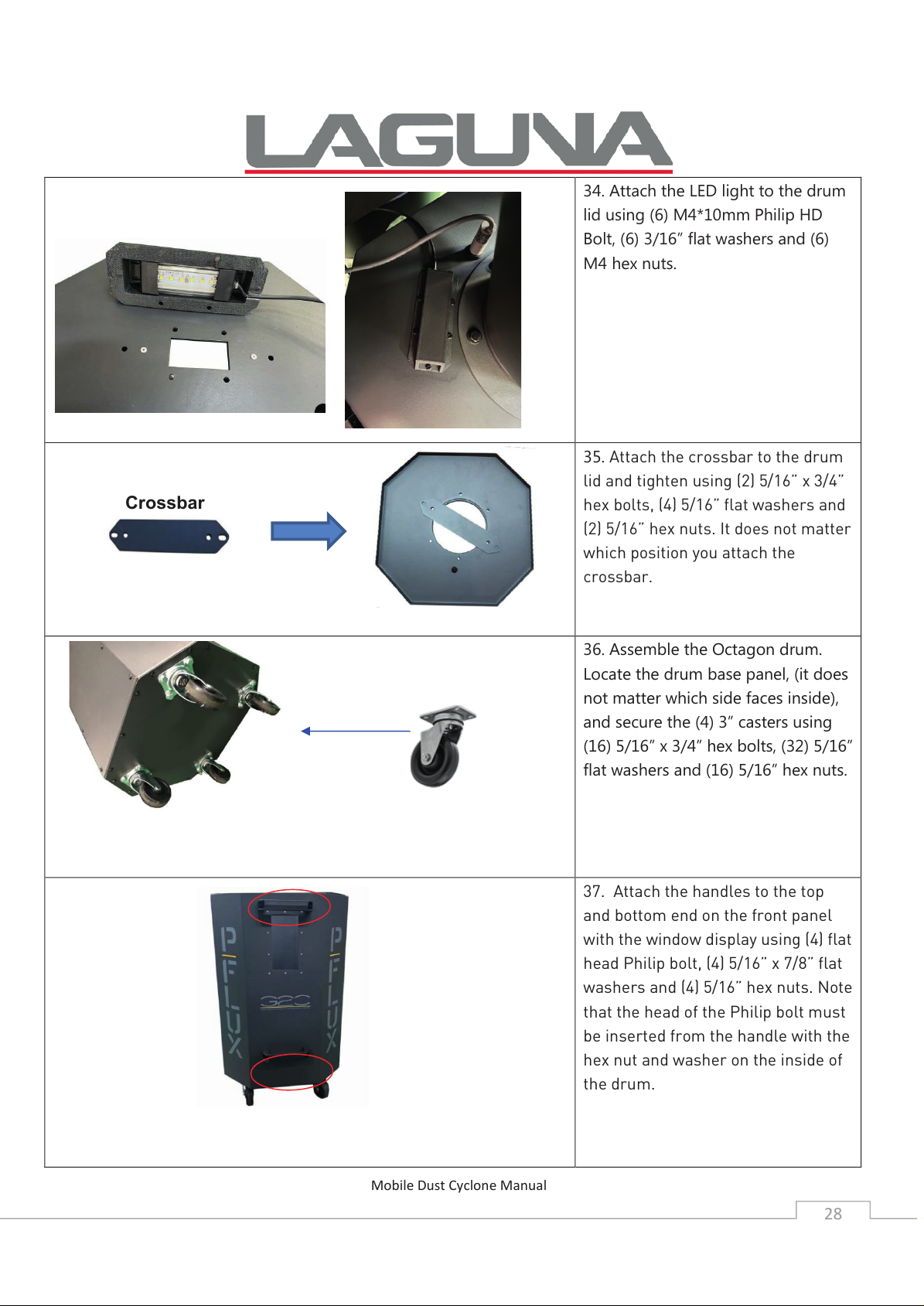
34. Attach the LED light to the drum
lid using (6) M4*10mm Philip HD
Bolt, (6) 3/16” flat washers and (6)
M4 hex nuts.
35. Attach the crossbar to the drum
lid and tighten using (2) 5/16” x 3/4”
hex bolts, (4) 5/16” flat washers and
(2) 5/16” hex nuts. It does not matter
which position you attach the
crossbar.
36. Assemble the Octagon drum.
Locate the drum base panel, (it does
not matter which side faces inside),
and secure the (4) 3” casters using
(16) 5/16” x 3/4” hex bolts, (32) 5/16”
flat washers and (16) 5/16” hex nuts.
37. Attach the handles to the top
and bottom end on the front panel
with the window display using (4) flat
head Philip bolt, (4) 5/16” x 7/8” flat
washers and (4) 5/16” hex nuts. Note
that the head of the Philip bolt must
be inserted from the handle with the
hex nut and washer on the inside of
the drum.
Crossbar
Page 29
Mobile Dust Cyclone Manual
29
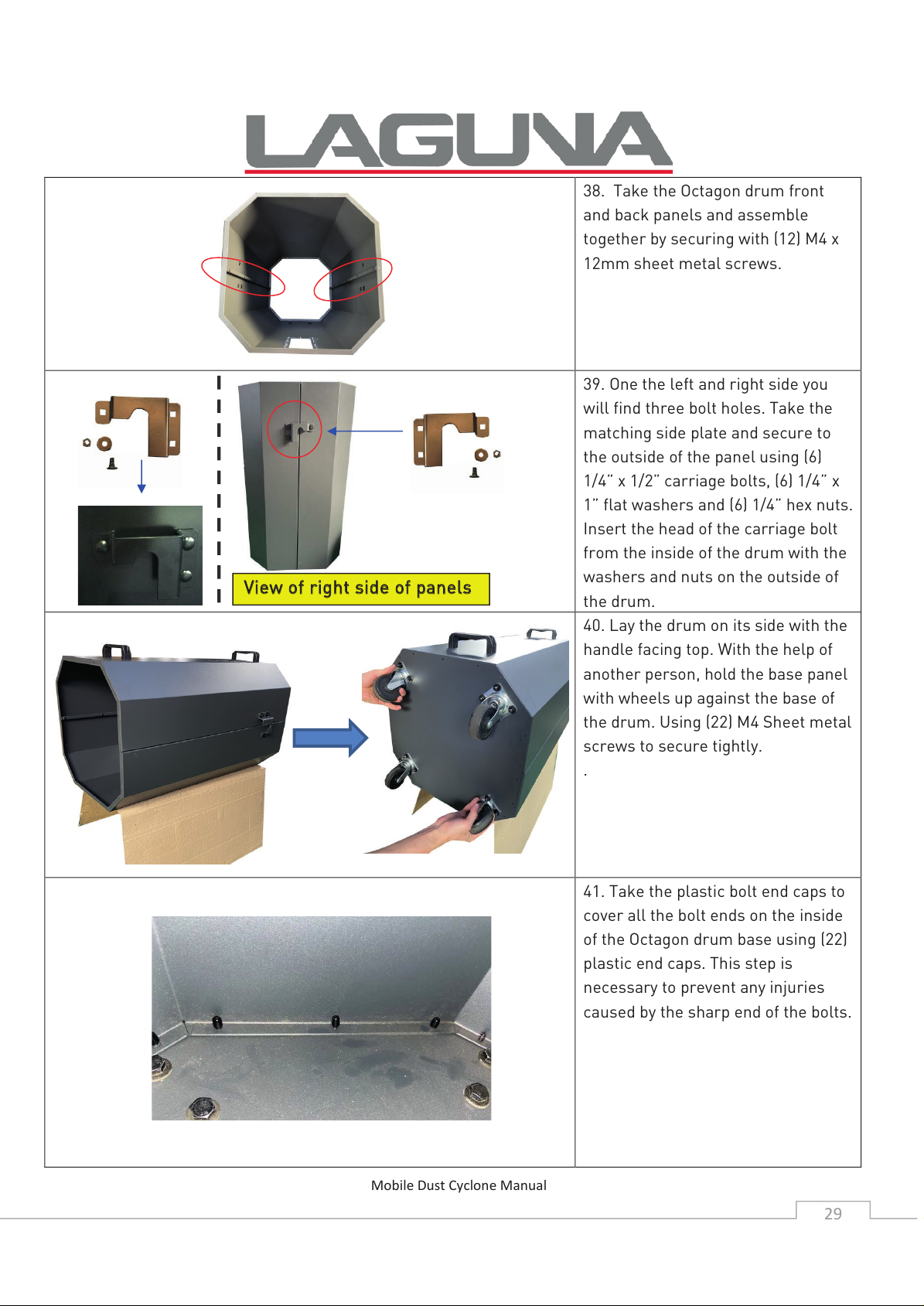
38. Take the Octagon drum front
and back panels and assemble
together by securing with (12) M4 x
12mm sheet metal screws.
39. One the left and right side you
will find three bolt holes. Take the
matching side plate and secure to
the outside of the panel using (6)
1/4” x 1/2” carriage bolts, (6) 1/4” x
1” flat washers and (6) 1/4” hex nuts.
Insert the head of the carriage bolt
from the inside of the drum with the
washers and nuts on the outside of
the drum.
40. Lay the drum on its side with the
handle facing top. With the help of
another person, hold the base panel
with wheels up against the base of
the drum. Using (22) M4 Sheet metal
screws to secure tightly.
.
41. Take the plastic bolt end caps to
cover all the bolt ends on the inside
of the Octagon drum base using (22)
plastic end caps. This step is
necessary to prevent any injuries
caused by the sharp end of the bolts.
VViieeww ooff rriigghhtt ssiiddee ooff ppaanneellss
Page 30
Mobile Dust Cyclone Manual
30
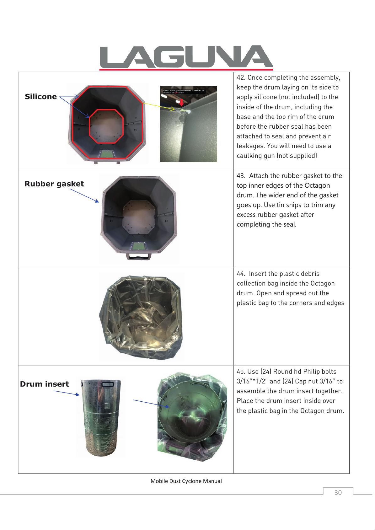
42. Once completing the assembly,
keep the drum laying on its side to
apply silicone (not included) to the
inside of the drum, including the
base and the top rim of the drum
before the rubber seal has been
attached to seal and prevent air
leakages. You will need to use a
caulking gun (not supplied)
43. Attach the rubber gasket to the
top inner edges of the Octagon
drum. The wider end of the gasket
goes up. Use tin snips to trim any
excess rubber gasket after
completing the seal.
44. Insert the plastic debris
collection bag inside the Octagon
drum. Open and spread out the
plastic bag to the corners and edges
45. Use (24) Round hd Philip bolts
3/16”*1/2” and (24) Cap nut 3/16” to
assemble the drum insert together.
Place the drum insert inside over
the plastic bag in the Octagon drum.
Silicone
Rubber gasket
Drum insert
Page 31
Mobile Dust Cyclone Manual
31
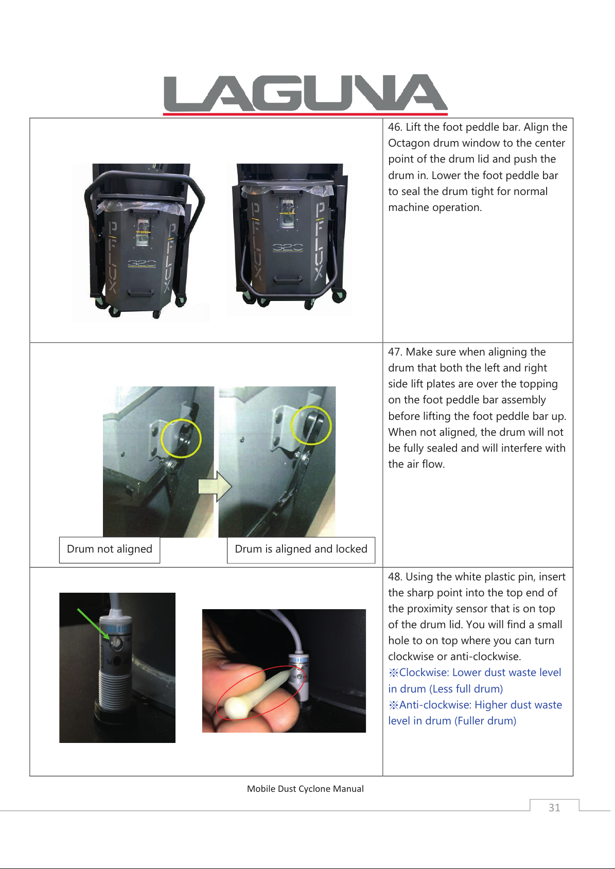
46. Lift the foot peddle bar. Align the
Octagon drum window to the center
point of the drum lid and push the
drum in. Lower the foot peddle bar
to seal the drum tight for normal
machine operation.
47. Make sure when aligning the
drum that both the left and right
side lift plates are over the topping
on the foot peddle bar assembly
before lifting the foot peddle bar up.
When not aligned, the drum will not
be fully sealed and will interfere with
the air flow.
48. Using the white plastic pin, insert
the sharp point into the top end of
the proximity sensor that is on top
of the drum lid. You will find a small
hole to on top where you can turn
clockwise or anti-clockwise.
※Clockwise: Lower dust waste level
in drum (Less full drum)
※Anti-clockwise: Higher dust waste
level in drum (Fuller drum)
Drum is aligned and locked Drum not aligned
Page 32
Mobile Dust Cyclone Manual
32
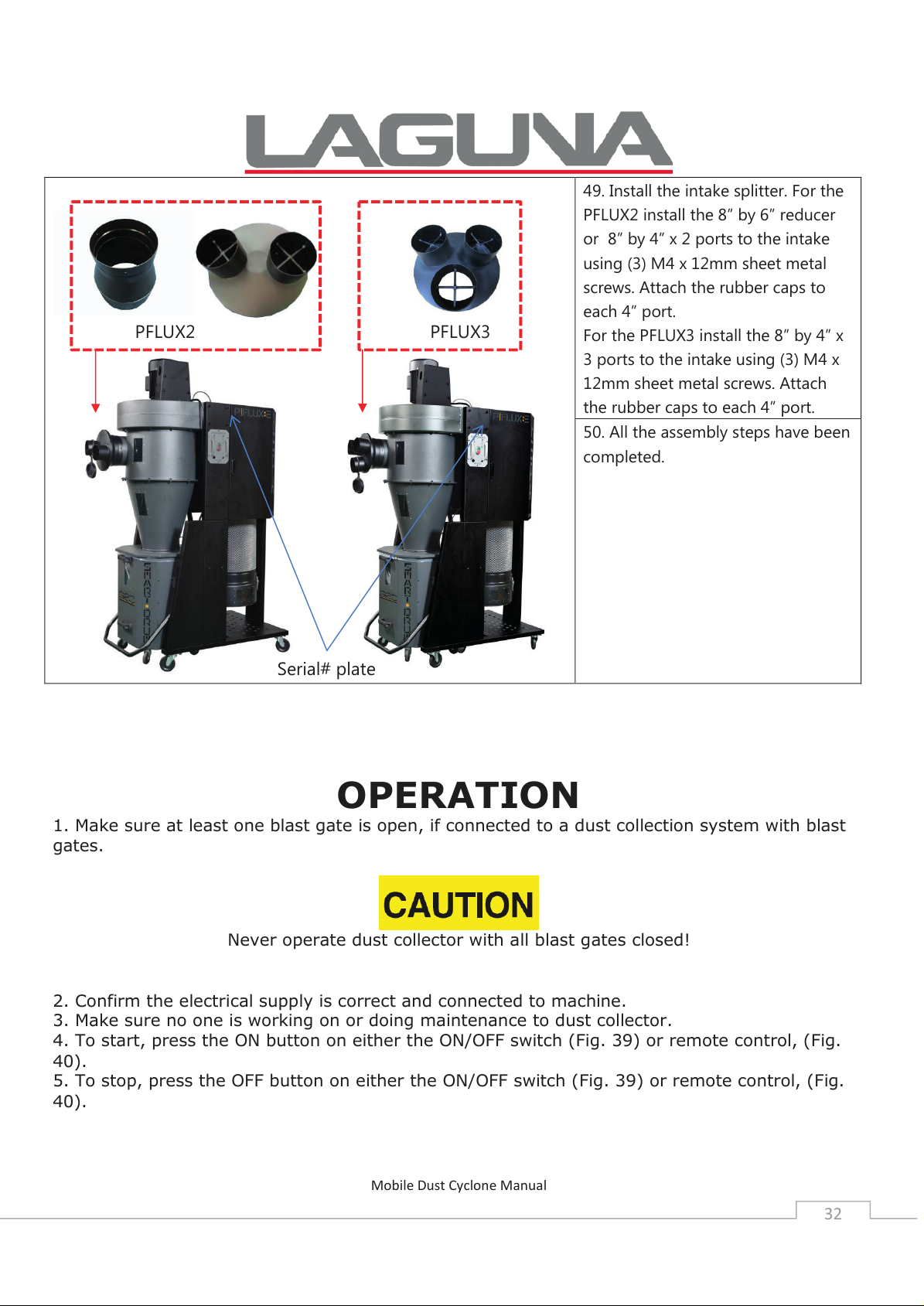
49. Install the intake splitter. For the
PFLUX2 install the 8” by 6” reducer
or 8” by 4” x 2 ports to the intake
using (3) M4 x 12mm sheet metal
screws. Attach the rubber caps to
each 4” port.
For the PFLUX3 install the 8” by 4” x
3 ports to the intake using (3) M4 x
12mm sheet metal screws. Attach
the rubber caps to each 4” port.
50. All the assembly steps have been
completed.
OPERATION
1. Make sure at least one blast gate is open, if connected to a dust collection system with blast
gates.
Never operate dust collector with all blast gates closed!
2. Confirm the electrical supply is correct and connected to machine.
3. Make sure no one is working on or doing maintenance to dust collector.
4. To start, press the ON button on either the ON/OFF switch (Fig. 39) or remote control, (Fig.
40).
5. To stop, press the OFF button on either the ON/OFF switch (Fig. 39) or remote control, (Fig.
40).
PFLUX2
Serial# plate
PFLUX3
Page 33
Mobile Dust Cyclone Manual
33
MAINTENANCE
CLEANING THE FILTER
This PFLUX2/PFLUX3 is equipped with auto clean every 10 minutes for 10 seconds one direction
and another 10 seconds the other direction. The cleaning will continue for one cycle (10 seconds
clockwise, 10 seconds counterclockwise when you shut the machine off. While the canister is
cleaning the yellow LED light on the control panel will illuminate showing that it is in the process
of cleaning.
There is a HEPA filter replacement indicator, which is the same yellow LED light as the cleaning
one. This is based on a timer system and when 2000 hours of running is reached, the light
indication would be flash constantly in one long, two short intervals meaning the HEPA filter
would need to be replaced.
Pressing the REMOTE button five times will reset the flashing light.
To ensure proper operation of this Mobile Dust Cyclone, the HEPA canister filter must have
adequate air flow. This means the filter must be regularly maintained by carefully blowing the
filter clean using compressed air and an air gun to release built-up particulates trapped between
the filter pleats.
DISCONNECT MACHINE FROM POWER!
For heavy duty users, it is recommended to use compressed air on a weekly basis to maintain
maximum filtration efficiency and longer life span of the filter.
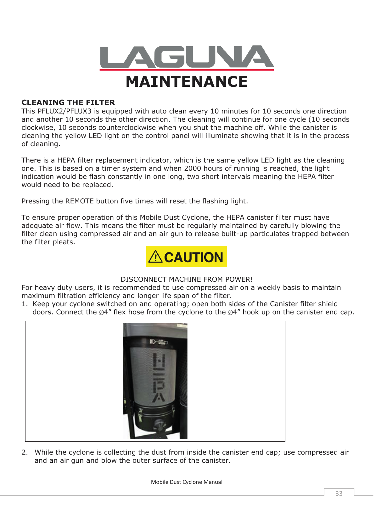
1. Keep your cyclone switched on and operating; open both sides of the Canister filter shield
doors. Connect the Ø4” flex hose from the cyclone to the Ø4” hook up on the canister end cap.
2. While the cyclone is collecting the dust from inside the canister end cap; use compressed air
and an air gun and blow the outer surface of the canister.
Page 34
Mobile Dust Cyclone Manual
34
3. After cleaning the filter with the compressed air gun, follow the steps in the next section to
remove the end cap to empty out any dust left inside.
EMPTYING THE CANISTER END CAP
Periodically check the canister end cap, if it is more than one third full, it is recommended that
you empty it.
NOTE: If the canister end cap gets too full, the dust particulates may be recirculated back into
the canister filter obstructing air flow and exposing the user to potentially harmful particulates.
1. Release the (4) latches around the canister end cap to remove..
2. Empty and re-attach using the latches.
EMPTYING THE DRUM
Periodically inspect the contents of the drum and empty as needed. To inspect the contents of
the drum:
1. Raise the drum foot peddle bar to lower the drum to the floor.
2. Roll it away from the machine, inspect and empty as needed.
HEPA FILTER REPLACMENT
To maintain safe, clean air quality, the HEPA filter should be replaced after 2000 hours of
operation (e.g., 8 hours/day x 250 days = 2,000 hours). Contact your dealer or Laguna Tools for
a replacement HEPA filter. If your model has a “change filter indicator light” it will flash at 2,000
hours. Replace HEPA filter. To reset flashing light, press the “Remote” button on the Control
Panel 5 times.
DISCONNECT MACHINE FROM POWER!
REMOVING THE CANISTER FILTER
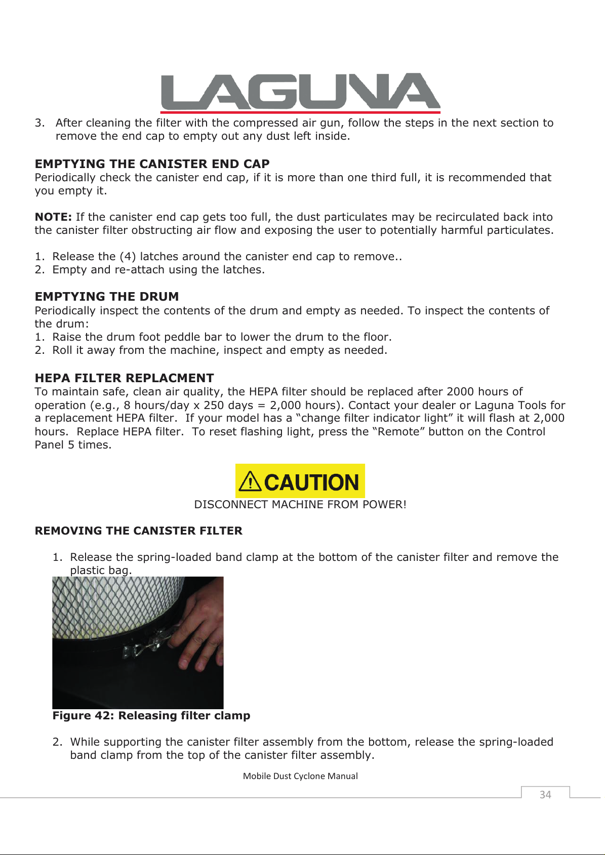
1. Release the spring-loaded band clamp at the bottom of the canister filter and remove the
plastic bag.
Figure 42: Releasing filter clamp
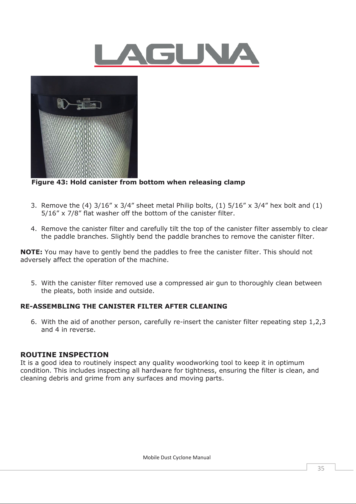
2. While supporting the canister filter assembly from the bottom, release the spring-loaded
band clamp from the top of the canister filter assembly.
Page 35
Mobile Dust Cyclone Manual
35
Figure 43: Hold canister from bottom when releasing clamp
3. Remove the (4) 3/16” x 3/4” sheet metal Philip bolts, (1) 5/16” x 3/4” hex bolt and (1)
5/16” x 7/8” flat washer off the bottom of the canister filter.
4. Remove the canister filter and carefully tilt the top of the canister filter assembly to clear
the paddle branches. Slightly bend the paddle branches to remove the canister filter.
NOTE: You may have to gently bend the paddles to free the canister filter. This should not
adversely affect the operation of the machine.
5. With the canister filter removed use a compressed air gun to thoroughly clean between
the pleats, both inside and outside.
RE-ASSEMBLING THE CANISTER FILTER AFTER CLEANING
6. With the aid of another person, carefully re-insert the canister filter repeating step 1,2,3
and 4 in reverse.
ROUTINE INSPECTION
It is a good idea to routinely inspect any quality woodworking tool to keep it in optimum
condition. This includes inspecting all hardware for tightness, ensuring the filter is clean, and
cleaning debris and grime from any surfaces and moving parts.
Page 36
TROUBLESHOOTING
Symptom
Possible Cause
Possible Solution
Machine does
not start or a
breaker trips.
Power supply switched OFF
or is faulty.
Wall fuse/circuit breaker is
blown/tripped.
Faulty remote control.
Remote receiver is faulty.
Incorrectly wired motor
connection.
On-board circuit breaker is
tripped.
Wiring is open/has high
resistance.
Faulty power switch.
Motor is at fault.
Ensure power supply is ON and has the
correct voltage.
Ensure adequate circuit size; install inlet
restrictor, replace weak breaker.
Replace batteries; ensure un-obstructed
line-of-sight and signal range.
Inspect receiver circuit board; replace if
faulty.
Rewire or call certified service technician
or electrician.
Allow motor to cool, improve ventilation,
press reset button.
Check for broken wires or poor
connections, repair as necessary.
Replace switch.
Test/repair/replace.
Excessive
vibration or
noise during
operation.
Loose component.
Loose or broken motor
mount.
Motor fan hitting fan cover.
Bad motor bearings.
Inspect and tighten all bolts/nuts.
Tighten or replace as needed.
Check fan and cover; replace as needed.
Rotate shaft manually, check for
grinding or loose shaft, replace bearings
if needed.
Mobile Dust Cyclone Manual
36
TROUBLESHOOTING
Symptom
Possible Cause
Possible Solution
Machine does
not start or a
breaker trips.
Power supply switched OFF
or is faulty.
Wall fuse/circuit breaker is
blown/tripped.
Faulty remote control.
Remote receiver is faulty.
Incorrectly wired motor
connection.
On-board circuit breaker is
tripped.
Wiring is open/has high
resistance.
Faulty power switch.
Motor is at fault.
Ensure power supply is ON and has the
correct voltage.
Ensure adequate circuit size; install inlet
restrictor, replace weak breaker.
Replace batteries; ensure un-obstructed
line-of-sight and signal range.
Inspect receiver circuit board; replace if
faulty.
Rewire or call certified service technician
or electrician.
Allow motor to cool, improve ventilation,
press reset button.
Check for broken wires or poor
connections, repair as necessary.
Replace switch.
Test/repair/replace.
Excessive
vibration or
noise during
operation.
Loose component.
Loose or broken motor
mount.
Motor fan hitting fan cover.
Bad motor bearings.
Inspect and tighten all bolts/nuts.
Tighten or replace as needed.
Check fan and cover; replace as needed.
Rotate shaft manually, check for
grinding or loose shaft, replace bearings
if needed.
Loud,
repetitive
noise, or
excessive
vibration
coming from
cyclone
Machine is on uneven
surface.
Damaged/Unbalanced
impeller.
Loose connections.
Stabilize on a flat surface.
Inspect impeller for dents, bends, loose
fins. Replace if needed.
Check and re-tighten all fasteners.
Replace the motor and impeller.
Page 37
Impeller is loose.
Motor fan hitting fan cover.
Check fan and cover; replace as needed.
Dust cyclone
does not
adequately
collect dust or
chips; poor
performance.
Canister end cap is full.
Filter is dirty.
Restricted duct line.
Suction route is too long or
has too many sharp bends.
Wet lumber is clogging
ducts.
Leaks in the duct work or too
many open ports.
Inadequate velocity in the
main suction line.
Wrong size ducting/ports
used.
Empty canister end cap.
Clean filter.
Clean inlet splitter.
Move machine closer to the point of
suction, and rerun ducts to eliminate
sharp bends.
Use lumber with less than 20% moisture
content.
Repair all duct leaks and close any ports
not being used.
Increase velocity by opening 1 or 2
more blast gates to different branch
lines.
Re-size and re-install ducts and fittings.
Mobile Dust Cyclone Manual
37
Impeller is loose.
Motor fan hitting fan cover.
Check fan and cover; replace as needed.
Dust cyclone
does not
adequately
collect dust or
chips; poor
performance.
Canister end cap is full.
Filter is dirty.
Restricted duct line.
Suction route is too long or
has too many sharp bends.
Wet lumber is clogging
ducts.
Leaks in the duct work or too
many open ports.
Inadequate velocity in the
main suction line.
Wrong size ducting/ports
used.
Empty canister end cap.
Clean filter.
Clean inlet splitter.
Move machine closer to the point of
suction, and rerun ducts to eliminate
sharp bends.
Use lumber with less than 20% moisture
content.
Repair all duct leaks and close any ports
not being used.
Increase velocity by opening 1 or 2
more blast gates to different branch
lines.
Re-size and re-install ducts and fittings.
Impeller is loose.
Check fan and cover; replace as needed.
TROUBLESHOOTING
Symptom
Possible Cause
Possible Solution
TROUBLESHOOTING
Symptom
Possible Cause
Possible Solution
Machine does
not start or a
breaker trips.
Power supply switched OFF
or is faulty.
Wall fuse/circuit breaker is
blown/tripped.
Faulty remote control.
Remote receiver is faulty.
Incorrectly wired motor
connection.
On-board circuit breaker is
tripped.
Wiring is open/has high
resistance.
Faulty power switch.
Motor is at fault.
Ensure power supply is ON and has the
correct voltage.
Ensure adequate circuit size; install inlet
restrictor, replace weak breaker.
Replace batteries; ensure un-obstructed
line-of-sight and signal range.
Inspect receiver circuit board; replace if
faulty.
Rewire or call certified service technician
or electrician.
Allow motor to cool, improve ventilation,
press reset button.
Check for broken wires or poor
connections, repair as necessary.
Replace switch.
Test/repair/replace.
Excessive
vibration or
noise during
operation.
Loose component.
Loose or broken motor
mount.
Motor fan hitting fan cover.
Bad motor bearings.
Inspect and tighten all bolts/nuts.
Tighten or replace as needed.
Check fan and cover; replace as needed.
Rotate shaft manually, check for
grinding or loose shaft, replace bearings
if needed.
Page 38
Mobile Dust Cyclone Manual
38
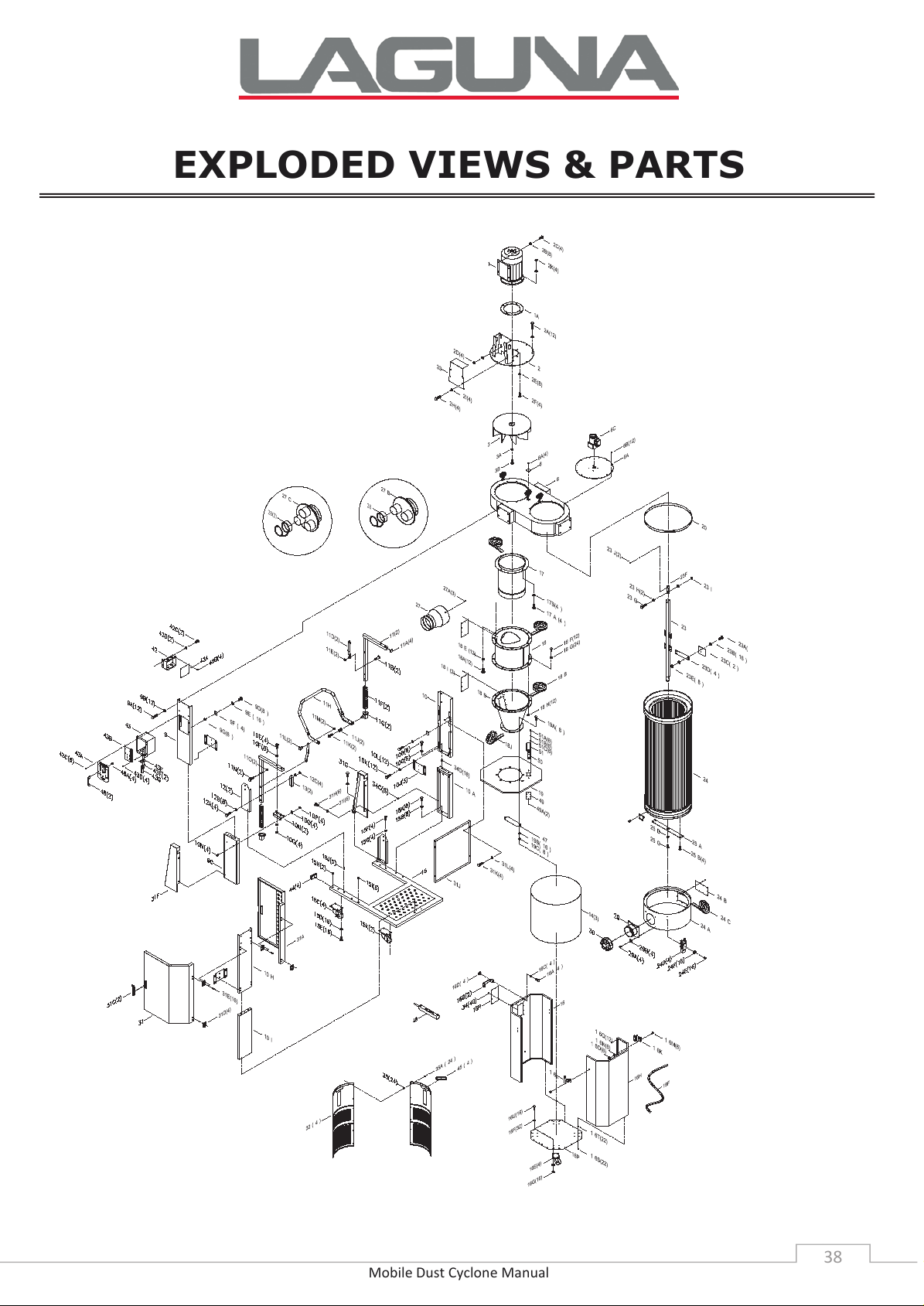
EXPLODED VIEWS & PARTS
2021.10.14
出圖章
山富機械公司
Page 39
Mobile Dust Cyclone Manual
39
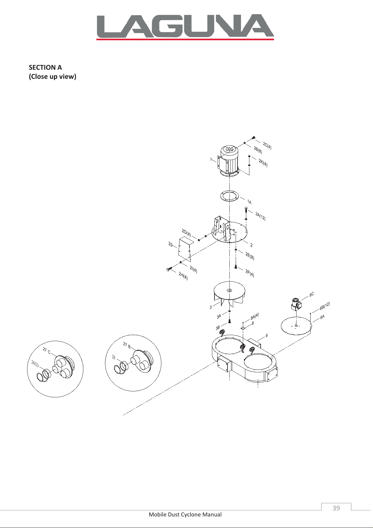
SECTION A
(Close up view)
Page 40
Mobile Dust Cyclone Manual
40
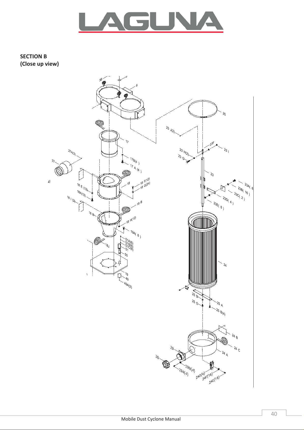
SECTION B
(Close up view)
Page 41
Mobile Dust Cyclone Manual
41
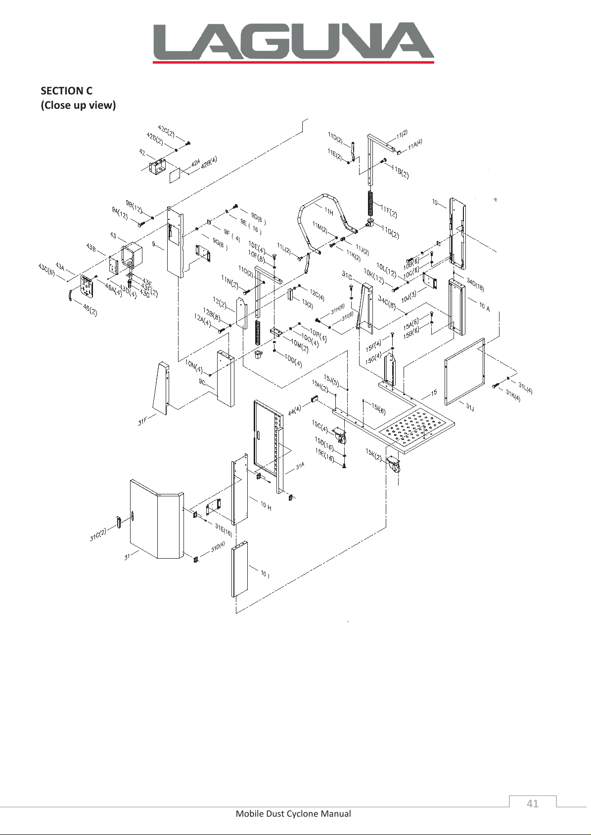
SECTION C
(Close up view)
Page 42
Mobile Dust Cyclone Manual
42
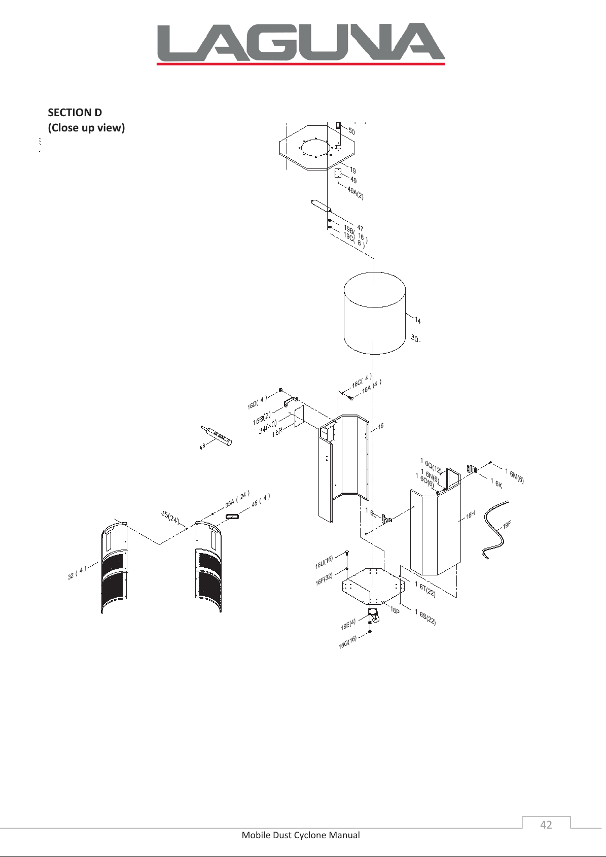
SECTION D
(Close up view)
Page 43
Mobile Dust Cyclone Manual
43
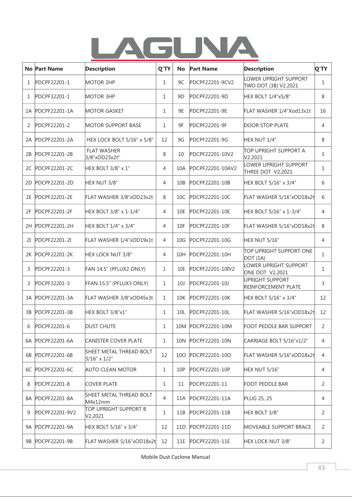
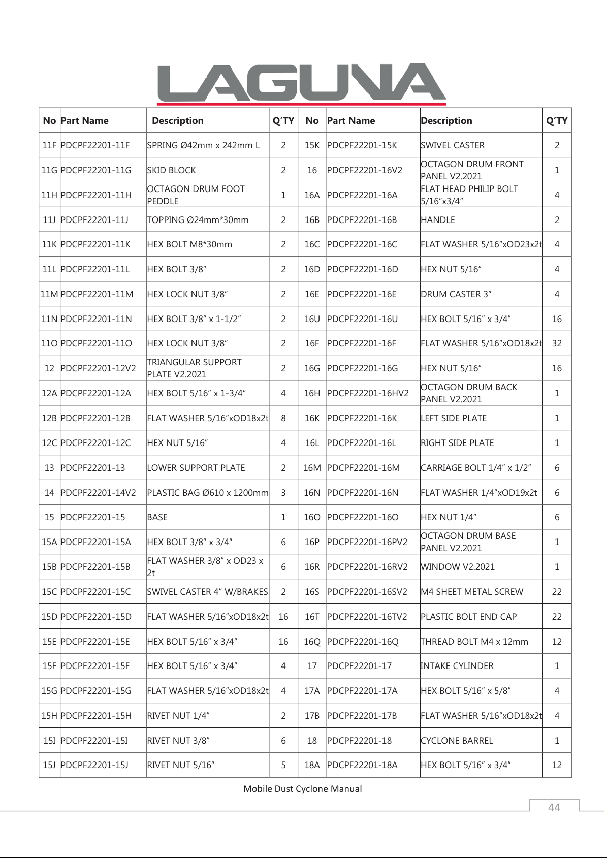
No
Part Name
Description
Q’TY No
Part Name
Description
Q’TY
1
PDCPF22201
-1
MOTOR
2HP 1 9C
PDCPF22201
-9CV2
LOWER UPRIGHT SUPPORT
TWO DOT (3B) V2.2021
1
1
PDCPF
32201-1
MOTOR
3HP 1 9D
PDCPF22201
-9D
HEX BOLT 1/4”x5/8”
8
1A
PDCPF22201
-1A
MOTOR GASKET
1 9E
PDCPF22201
-9E
FLAT WASHER 1/4”Xod13x1t
16
2
PDCPF22201
-2
MOTOR SUPPORT BASE
1 9F
PDCPF22201
-9F
DOOR STOP PLATE
4
2A
PDCPF22201
-2A
HEX LOCK BOLT 5/16” x 5/8” 12 9G
PDCPF22201
-9G
HEX
NUT 1/4” 8
2B
PDCPF22201
-2B
FLAT WASHER
3/8”xOD23x2t”
8 10
PDCPF22201
-10V2
TOP UPRIGHT SUPPORT A
V2.2021
1
2C
PDCPF22201
-2C
HEX BOLT 3/8” x 1”
4 10A
PDCPF22201
-10AV2
LOWER UPRIGHT SUPPORT
THREE DOT V2.2021
1
2D
PDCPF22201
-2D
HEX NUT 3/8”
4 10B
PDCPF22201
-10B
HEX BOLT 5/16” x 3/4”
6
2E
PDCPF22201
-2E
FLAT WASHER 3/8”xOD23x2t
8 10C
PDCPF22201
-10C
FLAT WASHER 5/16”xOD18x2t
6
2F
PDCPF22201
-2F
HEX BOLT 3/8” x 1
-1/4” 4 10E
PDCPF22201
-10E
HEX BOLT 5/16” x 1
-3/4” 4
2H
PDCPF22201
-2H
HEX BOLT 1/4” x
3/4” 4 10F
PDCPF22201
-10F
FLAT WASHER 5/16”xOD18x2t
8
2I
PDCPF22201
-2I
FLAT WASHER 1/4”xOD19x1t
4 10G
PDCPF22201
-10G
HEX NUT 5/16”
4
2K
PDCPF22201
-2K
HEX LOCK NUT 3/8"
4 10H
PDCPF22201
-10H
TOP UPRIGHT SUPPORT ONE
DOT (1A)
1
3
PDCPF22201
-3
FAN 14.5”
(PFLUX2 ONLY) 1 10I
PDCPF22201
-10IV2
LOWER UPRIGHT SUPPORT
ONE DOT V2.2021
1
3
PDCPF
32201-3
F
FAN 15.5” (PFLUX3 ONLY) 1 10J
PDCPF22201
-10J
UPRIGHT SUPPORT
REINFORCEMENT PLATE
3
3A
PDCPF22201
-3A
FLAT WASHER 3/8”xOD45x3t
1 10K
PDCPF22201
-10K
HEX BOLT
5/16” x 3/4” 12
3B
PDCPF22201
-3B
HEX BOLT 3/8”x1”
1 10L
PDCPF22201
-10L
FLAT WASHER 5/16”xOD18x2t
12
6
PDCPF22201
-6
DUST CHUTE
1 10M
PDCPF22201
-10M
FOOT PEDDLE BAR SUPPORT
2
6A
PDCPF22201
-6A
CANISTER COVER PLATE
1 10N
PDCPF22201
-10N
CARRIAGE BOLT
5/16”x1/2” 4
6B
PDCPF22201
-6B
SHEET METAL THREAD BOLT
3/16” x 1/2”
12 10O
PDCPF22201
-10O
FLAT WASHER 5/16”xOD18x2t
4
6C
PDCPF22201
-6C
AUTO CLEAN MOTOR
1 10P
PDCPF22201
-10P
HEX NUT 5/16”
4
8
PDCPF22201
-8
COVER PLATE
1 11
PDCPF22201
-11
FOOT PEDDLE BAR
2
8A
PDCPF22201
-8A
SHEET METAL THREAD BOLT
M4x12mm
4 11A
PDCPF22201
-11A
PLUG 25, 25
4
9
PDCPF22201
-9V2
TOP UPRIGHT SUPPORT B
V2.2021
1 11B
PDCPF22201
-11B
HEX BOLT 3/8”
2
9A
PDCPF22201
-9A
HEX BOLT 5/16” x 3/4”
12 11D
PDCPF22201
-11D
MOVEABLE SUPPORT BRACE
2
9B
PDCPF22201
-9B
FLAT WASHER 5/16”xOD18x2t
12 11E
PDCPF22201
-11E
HEX LOCK NUT 3/8”
2
Page 44
Mobile Dust Cyclone Manual
44
No
Part Name
Description Q’TY No
Part Name
Description
Q’TY
11F
PDCPF22201
-11F
SPRING Ø42mm x 242mm L
2 15K
PDCPF22201
-15K
SWIVEL CASTER
2
11G
PDCPF22201
-11G
SKID
BLOCK 2 16
PDCPF22201
-16V2
OCTAGON DRUM FRONT
PANEL V2.2021
1
11H
PDCPF22201
-11H
OCTAGON DRUM FOOT
PEDDLE
1 16A
PDCPF22201
-16A
FLAT HEAD PHILIP BOLT
5/16”x3/4”
4
11J
PDCPF22201
-11J
TOPPING Ø24mm*30mm
2 16B
PDCPF22201
-16B
HANDLE
2
11K
PDCPF22201
-11K
HEX
BOLT M8*30mm 2 16C
PDCPF22201
-16C
FLAT WASHER 5/16”xOD23x2t
4
11L
PDCPF22201
-11L
HEX BOLT 3/8”
2 16D
PDCPF22201
-16D
HEX NUT 5/16”
4
11M
PDCPF22201
-11M
HEX LOCK NUT 3/8”
2 16E
PDCPF22201
-16E
DRUM CASTER 3”
4
11N
PDCPF22201
-11N
HEX BOLT 3/8” x 1
-1/2” 2 16U
PDCPF22201
-16U
HEX BOLT 5/16” x 3/4”
16
11O
PDCPF22201
-11O
HEX LOCK NUT 3/8”
2 16F
PDCPF22201
-16F
FLAT WASHER 5/16”xOD18x2t
32
12
PDCPF22201
-12V2
TRIANGULAR SUPPORT
PLATE V2.2021
2 16G
PDCPF22201
-16G
HEX NUT 5/16”
16
12A
PDCPF22201
-12A
HEX BOLT
5/16” x 1-3/4” 4 16H
PDCPF22201
-16HV2
OCTAGON DRUM BACK
PANEL V2.2021
1
12B
PDCPF22201
-12B
FLAT WASHER 5/16”xOD18x2t
8 16K
PDCPF22201
-16K
LEFT SIDE PLATE
1
12C
PDCPF22201
-12C
HEX NUT 5/16”
4 16L
PDCPF22201
-16L
RIGHT SIDE PLATE
1
13
PDCPF22201
-13
LOWER
SUPPORT PLATE 2 16M
PDCPF22201
-16M
CARRIAGE BOLT 1/4” x 1/2”
6
14
PDCPF22201
-14V2
PLASTIC BAG Ø610 x 1200mm
3 16N
PDCPF22201
-16N
FLAT WASHER 1/4”xOD19x2t
6
15
PDCPF22201
-15
BASE
1 16O
PDCPF22201
-16O
HEX NUT 1/4”
6
15A
PDCPF22201
-15A
HEX BOLT 3/8” x 3/4”
6 16P
PDCPF22201
-16PV2
OCTAGON DRUM BASE
PANEL V2.2021
1
15B
PDCPF22201
-15B
FLAT WASHER 3/8” x OD23 x
2t
6 16R
PDCPF22201
-16RV2
WINDOW V2.2021
1
15C
PDCPF22201
-15C
SWIVEL CASTER 4” W/BRAKES
2 16S
PDCPF22201
-16SV2
M4
SHEET METAL SCREW 22
15D
PDCPF22201
-15D
FLAT WASHER 5/16”xOD18x2t
16 16T
PDCPF22201
-16TV2
PLASTIC BOLT END CAP
22
15E
PDCPF22201
-15E
HEX BOLT 5/16” x 3/4”
16 16Q
PDCPF22201
-16Q
THREAD BOLT M4 x 12mm
12
15F
PDCPF22201
-15F
HEX BOLT 5/16” x 3/4”
4 17
PDCPF22201
-17
INTAKE CYLINDER
1
15G
PDCPF22201
-15G
FLAT WASHER 5/16”xOD18x2t
4 17A
PDCPF22201
-17A
HEX BOLT 5/16” x 5/8”
4
15H
PDCPF22201
-15H
RIVET NUT 1/4”
2 17B
PDCPF22201
-17B
FLAT WASHER 5/16”xOD18x2t
4
15I
PDCPF22201
-15I
RIVET NUT 3/8”
6 18
PDCPF22201
-18
CYCLONE BARREL
1
15J
PDCPF22201
-15J
RIVET NUT 5/16”
5 18A
PDCPF22201
-18A
HEX BOLT 5/16” x 3/4”
12
Page 45
Mobile Dust Cyclone Manual
45
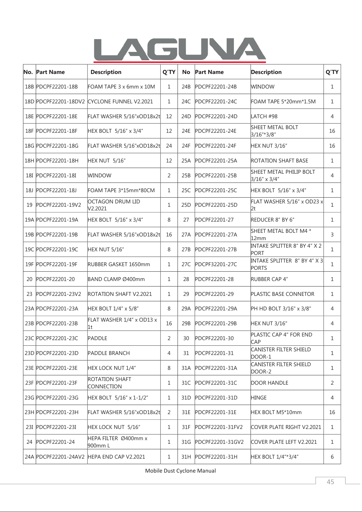
No. Part Name
Description Q’TY No
Part Name
Description
Q’TY
18B
PDCPF22201
-18B
FOAM TAPE 3 x 6mm x 10M
1 24B
PDCPF22201
-24B
WINDOW
1
18D
PDCPF22201
-18DV2
CYCLONE FUNNEL
V2.2021 1 24C
PDCPF22201
-24C
FOAM TAPE 5*20mm*1.5M
1
18E
PDCPF22201
-18E
FLAT WASHER 5/16”xOD18x2t
12 24D
PDCPF22201
-24D
LATCH #98
4
18F
PDCPF22201
-18F
HEX BOLT 5/16” x 3/4”
12 24E
PDCPF22201
-24E
SHEET METAL BOLT
3/16”*3/8”
16
18G
PDCPF22201
-18G
FLAT
WASHER 5/16”xOD18x2t 24 24F
PDCPF22201
-24F
HEX NUT 3/16”
16
18H
PDCPF22201
-18H
HEX NUT 5/16”
12 25A
PDCPF22201
-25A
ROTATION SHAFT BASE
1
18I
PDCPF22201
-18I
WINDOW
2 25B
PDCPF22201
-25B
SHEET METAL PHILIP BOLT
3/16” x 3/4”
4
18J
PDCPF22201
-18J
FOAM TAPE
3*15mm*80CM 1 25C
PDCPF22201
-25C
HEX BOLT 5/16” x 3/4”
1
19
PDCPF22201
-19V2
OCTAGON DRUM LID
V2.2021
1 25D
PDCPF22201
-25D
FLAT WASHER 5/16” x OD23 x
2t
1
19A
PDCPF22201
-19A
HEX BOLT 5/16” x 3/4”
8 27
PDCPF22201
-27
REDUCER 8” BY 6”
1
19B
PDCPF22201
-19B
FLAT WASHER 5/16”xOD18x2t
16 27A
PDCPF22201
-27A
SHEET METAL BOLT M4 *
12mm
3
19C
PDCPF22201
-19C
HEX NUT 5/16”
8 27B
PDCPF22201
-27B
INTAKE SPLITTER 8” BY 4” X 2
PORT
1
19F
PDCPF22201
-19F
RUBBER GASKET 1650mm
1 27C
PDCPF32201
-27C
INTAKE SPLITTER 8” BY 4” X 3
PORTS
1
20
PDCPF22201
-20
BAND CLAMP Ø400mm
1 28
PDCPF22201
-28
RUBBER CAP 4”
1
23
PDCPF22201
-23V2
ROTATION SHAFT V2.2021
1 29
PDCPF22201
-29
PLASTIC BASE CONNETOR
1
23A
PDCPF22201
-23A
HEX BOLT 1/4” x 5/8”
8 29A
PDCPF22201
-29A
PH HD
BOLT 3/16" x 3/8" 4
23B
PDCPF22201
-23B
FLAT WASHER 1/4” x OD13 x
1t
16 29B
PDCPF22201
-29B
HEX NUT 3/16"
4
23C
PDCPF22201
-23C
PADDLE
2 30
PDCPF22201
-30
PLASTIC CAP 4" FOR END
CAP
1
23D
PDCPF22201
-23D
PADDLE BRANCH
4 31
PDCPF22201
-31
CANISTER FILTER SHIELD
DOOR-1
1
23E
PDCPF22201
-23E
HEX LOCK NUT 1/4”
8 31A
PDCPF22201
-31A
CANISTER FILTER SHIELD
DOOR-2
1
23F
PDCPF22201
-23F
ROTATION SHAFT
CONNECTION
1 31C
PDCPF22201
-31C
DOOR HANDLE
2
23G
PDCPF22201
-23G
HEX BOLT 5/16” x 1
-1/2” 1 31D
PDCPF22201
-31D
HINGE
4
23H
PDCPF22201
-23H
FLAT WASHER 5/16”xOD18x2t
2 31E
PDCPF22201
-31E
HEX BOLT M5*10mm
16
23I
PDCPF22201
-23I
HEX LOCK NUT 5/16”
1 31F
PDCPF22201
-31FV2
COVER PLATE RIGHT V2.2021
1
24
PDCPF22201
-24
HEPA FILTER Ø400mm x
900mm L
1 31G
PDCPF22201
-31GV2
COVER PLATE LEFT V2.2021
1
24A
PDCPF22201
-24AV2
HEPA END CAP V2.2021
1 31H
PDCPF22201
-31H
HEX BOLT 1/4”*3/4”
6
Page 46
Mobile Dust Cyclone Manual
46
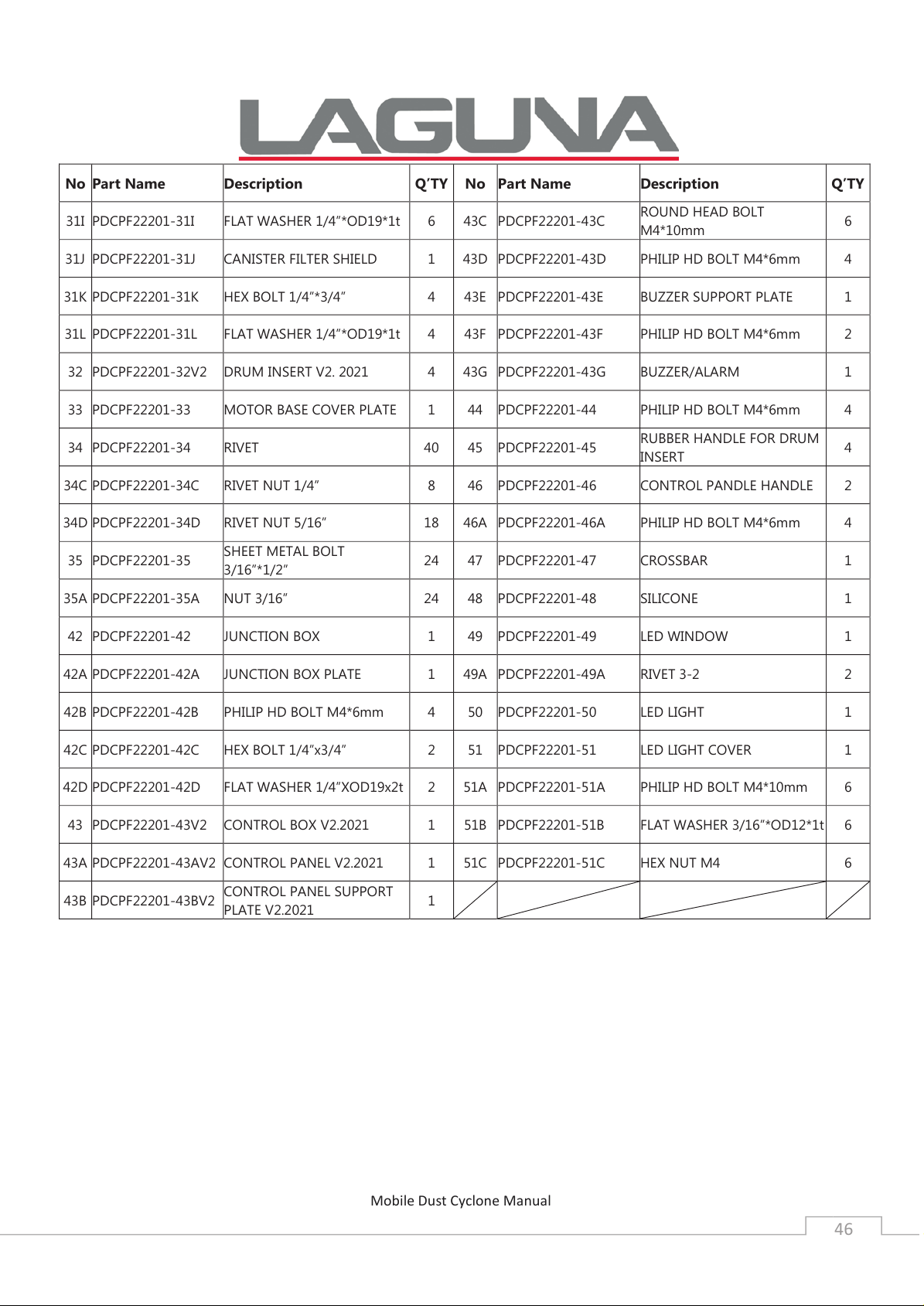
No
Part Name
Description
Q’TY No
Part Name
Description
Q’TY
31I
PDCPF22201
-31I
FLAT WASHER 1/4”*OD19*1t
6 43C
PDCPF22201
-43C
ROUND HEAD BOLT
M4*10mm
6
31J
PDCPF22201
-31J
CANISTER FILTER SHIELD
1 43D
PDCPF22201
-43D
PHILIP HD BOLT M4*6mm
4
31K
PDCPF22201
-31K
HEX BOLT 1/4”*3/4”
4 43E
PDCPF22201
-43E
BUZZER SUPPORT PLATE
1
31L
PDCPF22201
-31L
FLAT WASHER 1/4”*OD19*1t
4 43F
PDCPF22201
-43F
PHILIP HD BOLT M4*6mm
2
32
PDCPF22201
-32V2
DRUM INSERT V2. 2021
4 43G
PDCPF22201
-43G
BUZZER/ALARM
1
33
PDCPF22201
-33
MOTOR BASE COVER PLATE
1 44
PDCPF22201
-44
PHILIP HD BOLT M4*6mm
4
34
PDCPF22201
-34
RIVET
40 45
PDCPF22201
-45
RUBBER HANDLE FOR DRUM
INSERT
4
34C
PDCPF22201
-34C
RIVET NUT 1/4”
8 46
PDCPF22201
-46
CONTROL PANDLE HANDLE
2
34D
PDCPF22201
-34D
RIVET NUT 5/16”
18 46A
PDCPF22201
-46A
PHILIP HD BOLT M4*6mm
4
35
PDCPF22201
-35
SHEET METAL BOLT
3/16”*1/2”
24 47
PDCPF22201
-47
CROSSBAR
1
35A
PDCPF22201
-35A
NUT 3/16”
24 48
PDCPF22201
-48
SILICONE
1
42
PDCPF22201
-42
JUNCTION BOX
1 49
PDCPF22201
-49
LED WINDOW
1
42A
PDCPF22201
-42A
JUNCTION BOX PLATE
1 49A
PDCPF22201
-49A
RIVET 3
-2 2
42B
PDCPF22201
-42B
PHILIP HD BOLT M4*6mm
4 50
PDCPF22201
-50
LED
LIGHT 1
42C
PDCPF22201
-42C
HEX BOLT 1/4”x3/4”
2 51
PDCPF22201
-51
LED LIGHT COVER
1
42D
PDCPF22201
-42D
FLAT WASHER 1/4”XOD19x2t
2 51A
PDCPF22201
-51A
PHILIP HD BOLT M4*10mm
6
43
PDCPF22201
-43V2
CONTROL BOX V2.2021
1 51B
PDCPF22201
-51B
FLAT WASHER
3/16”*OD12*1t 6
43A
PDCPF22201
-43AV2
CONTROL PANEL V2.2021
1 51C
PDCPF22201
-51C
HEX NUT M4
6
43B
PDCPF22201
-43BV2
CONTROL PANEL SUPPORT
PLATE V2.2021
1
Page 47

Laguna Tools Inc.
UK DECLARATION OF CONFORMITY
‘original’
Product model: P/Flux 3 Cyclone Extractor
Name and address of the manufacturer: Laguna Tools Inc. 2072 Alton Parkway, Irvine, California
92606, USA.
Name and address of the UK Authorised Representative: Axminster Tool Centre Ltd, Unit 10 Weycroft
Avenue, Axminster, Devon EX13 5PH, United Kingdom.
This declaration of conformity is issued under the sole responsibility of the manufacturer.
Object of the declaration: P/Flux 3 Cyclone Extractor
The object of the declaration described above is in conformity with the relevant GB legislation:
Supply of Machinery (Safety) Regulations 2008 as amended.
Electromagnetic Compatibility Regulations 2016 as amended.
References to the relevant harmonised standards used or references to the other technical
specifications in relation to which conformity is declared:
.
EN ISO 12100:2010 Safety of machinery - General principles for design - Risk assessment and
risk reduction
EN 60204-1:2018 Safety of machinery - Electrical equipment of machines - Part 1: General
requirements
Additional information:
Name and address of person authorised to compile the technical file: Axminster Tool Centre
Ltd, Unit 10 Weycroft Avenue, Axminster, Devon EX13 5PH, United Kingdom
The machinery fulfils all relevant provisions of Supply of Machinery (Safety) Regulations 2008
as amended.
Signed for and behalf of: Axminster Tool Centre Ltd.
(place and date of issue): Axminster, Devon, United Kingdom, 20th June 2024
(name, function): Andrew Parkhouse, Supply Chain Director
Signature:
Page 48

Page 49

Warranty
New machines and accessories sold by Laguna Tools carry a one-year
warranty effective from the date of shipping.
Laguna Tools guarantees all new machines and accessories sold to be
free of manufacturers’ defective workmanship, parts and materials.
We will repair or replace, without charge, any parts determined by
Laguna Tools, Inc. to be a manufacturer’s defect.
We require that the defective item/part be returned to the Laguna
appointed dealer you purchased from with the complaint. Photographic / videos maybe required when any fault is reported so we can
agree action needed. Any machines returned to Laguna appointed dealer must be returned with packaging in the same manner
in which it was received. If a part or blade is being returned it must
have adequate packaging to ensure no damage is received during
shipping. In the event the item/part is determined to be damaged
due to lack of maintenance, cleaning or misuse/abuse, the customer
will be responsible for the cost to replace the item/part, plus all related shipping charges. This limited warranty does not apply to natural
disasters, acts of terrorism, normal wear and tear, product failure due
to lack of maintenance or cleaning, damage caused by accident,
neglect, lack of or inadequate dust collection, misuse/abuse or damage caused where repair or alterations have been made or attempted
by others. Laguna Tools, Inc. is not responsible for additional tools or
modifications sold or performed (other than from/by Laguna Tools,
Inc.) on any Laguna Tools, Inc. machine.
Warranty maybe voided upon the addition of such described tools
and/or modifications, determined on a case-by-case basis.
Normal user alignment, adjustment, tuning, machine settings and
consumables I.E; blades are not covered by this warranty. It is the
responsibility of the user to understand basic machinery operation,
settings and procedures and to properly maintain the equipment in
accordance with the standards provided by the manufacturer.
The labour required to install replacement parts is the responsibility
of the user. Laguna Tools is not responsible for damage or loss caused
by a freight company or other circumstances not in our control.
All claims for loss or damaged goods must be notified to the authorised dealer within twenty-four hours, if the machine is received damaged it must be signed for damaged.
Only new machines sold to the original owner are covered by this
warranty.
Page 50

Page 51

Page 52

Distributed by
The packaging is suitable for recycling.
Please dispose of it in a responsible manner.
EU Countries Only
Do not dispose of electric tools together with household waste material.
By law they must be collected and recycled separately.
For after sales help visit
axminstertools.com or call 03332 406406
Axminster Tools, Axminster Devon EX13 5PH
 Loading...