

Page 1
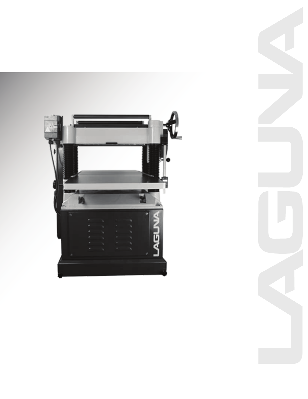
20” Planer with
ShearTec II Manual
LAGUNA TOOLS
2072 Alton Parkway
Irvine, California 92606
Ph: 800.234.1976
www.lagunatools.com
Model Numbers: MPLAN1200-0130
© 2018, Laguna Tools, Inc. LAGUNA® and the LAGUNA Logo® are the registered trademarks of Laguna Tools, Inc. All rights reserved.
Page 2

For Your Own Safety Read Instruction Manual Before Operating This Tool
Read this manual completely and observe all warning labels on the machine. This machine has made every attempt
to provide a safe, reliable, easy-to-use piece of machinery. Safety, however, is ultimately the responsibility of the
individual machine operator. As with any piece of machinery, the operator must exercise caution, patience, and
common sense to safely run the machine. Before operating this product, become familiar with the safety rules in the
following sections.
1. KEEP WORK AREA CLEAN. Cluttered areas and benches invite accidents.
2. DON'T USE IN DANGEROUS ENVIRONMENT. Don't use power tools in damp or wet locations, or
expose them to rain. Keep work area well lighted.
3. KEEP CHILDREN AWAY. All visitors should be kept safe distance from work area.
4. MAKE WORKSHOP KID PROOF with padlocks, master switches, or by removing starter keys.
5. USE RIGHT TOOL Don't force tool or attachment to do a job for which it was not designed.
6. WEAR PROPER APPAREL Do not wear loose clothing, gloves, neckties, rings, bracelets, or other
jewelry which may get caught in moving parts. Nonslip footwear is recommended. Wear protective hair
covering to contain long hair.
7. ALWAYS USE SAFETY GLASSES. Also use face or dust mask if cutting operation is dusty. Everyday
eyeglasses only have impact resistant lenses, they are NOT safety glasses.
8. SECURE WORK. Use clamps or a vise to hold work when practical. It's safer than using your hand and
it frees both hands to operate tool.
9. DON'T OVERREACH. Keep proper footing and balance at all times.
10. MAINTAIN TOOLS WITH CARE. Keep tools sharp and clean for best and safest performance. Follow
instructions for lubricating and changing accessories.
11. REDUCE THE RISK OF UNINTENTIONAL STARTING. Make sure switch is in off position before
plugging in.
12. USE RECOMMENDED ACCESSORIES. Consult the owner's manual for recommended accessories.
The use of improper accessories may cause risk of injury to persons.
13. CHECK DAMAGED PARTS. Before further use of the tool, a guard or other part that is damaged
should be carefully checked to determine that it will operate properly and perform its intended function check for alignment of moving parts, binding of moving parts, breakage of parts, mounting, and any
other conditions that may affect its operation.
A guard or other part that is damaged should be properly repaired or replaced.
14. DIRECTION OF FEED. Feed work into a blade or cutter against the direction of rotation of the blade or
cutter only.
15. NEVER LEAVE TOOL RUNNING UNATTENDED. TURN POWER OFF. Don't leave tool until it comes
to a complete stop.
16. Wear eye protection.
1
Page 3

Your risk from these exposures varies, depending on how often you do this type of work. To reduce
your exposure to these chemicals, work in a well-ventilated area, and work with approved safety
equipment, such as those dust masks that are specifically designed to filter out microscopic particles.
Familiarize yourself with the following safety notices used in this manual:
CAUTION: (This means that if precautions are not heeded, it may result in minor or moderate injury
and/or possible machine damage)
WARNING: (This means that if precautions are not heeded, it could result in serious injury or possibly
even death).
2
Page 4

20” PLANER
Thank you for choosing this planer.
This unit is carefully tested and inspected before
shipment and if properly used and maintained, will
provide you with 1 year of reliable service. To
ensure optimum performance and trouble
free operation a reasonable amount of care and
attention is required.
To get the most from your new planer, please take
the time to read this manual before assembling,
installing and operating the unit.
UNPACKING AND CLEANING
To ensure maximum performance from your 20"
planer, clean it properly; and install it accurately
before use. As soon as you receive the planer, we
recommend you follow these procedures:
1. Finish removing the contents of the shipping
carton and compare with the contents list.
2. Report damage, if any to your local distributor.
3. Clean all rust protected surfaces with a mild
solvent or kerosene. Do not use lacquer thinner;
paint thinner, or gasoline. These will damage
painted surfaces.
4. To prevent rust, apply a light coating of paste
wax to surface.
CARRIAGE
The planer has four lifting handles (A), pulled
them l out when needed, or pushed in when not in
use. (Fig.1)
USING A SLING
When using a sling to carry machine, lifting
handles must be pulled out (Fig.2). Try keeping
sling parallel to machine and hold steady.
ASSEMBLING
The base part of your planer can be fixed in place
with dimensional screws of 10 mm. (Fig.3)
SWITCH MAGNETIC
CONTACTOR CURCUIT FIG.3
- Single phase motor
- Power source: A,C in put
- Motor source : A,C, out put
- Grounding: D
Fig. 1
Fig. 2
Fig. 3
3
Page 5

ASSEMBLY EXTENSION TABLE
Ask another person provide assistance to hole on
the extension table. To lock up screws into the
holes (Fig. 4) then place straight edge through
machine let it lies across both table and extension
table (Fig.5). If they are not aligned, loosen
screws and adjust them until they are aligned then
tighten all of screws.
WARNING: Disconnect the machine from the
power source.
Fig. 4
DUST CHUTE ASSEMBLY
Mount the dust chute to the planer hood with
hex head screws & flat washer. Make sure the
dust collection system has sufficient capacity
and suction for your planer. Always turn
on the dust collection system before starting
the planer. (Fig. 6 )
Fig. 5
4
Fig. 6
Page 6

SHEARTEC 2 CUTTERHEAD
Knife inserts are dangerously
sharp. Use extreme caution when inspecting,
removing, or replacing knife inserts.
The knife inserts on the Jointer are four-sided.
When dull, simply remove each insert, rotate it
90° for a fresh edge, and re-install it. No further
adjustment is necessary. Use the two provided
torx wrench to remove the knife insert screw. Use
one of the torx wrenches to help hold the
cutterhead in Position, and the other to remove
the screw. See Fig. 7. It is advisable to rotate all
inserts at the same time to maintain consistent
cutting. However, if one or more knife inserts
develops a nick, rotate only those inserts that are
affected.
Each knife insert has an etched reference mark
so you can keep track of the rotations.
IMPORTANT: When removing or rotating inserts,
clean saw dust from the screw, the insert, and the
cutterhead platform. Dust accumulation between
these elements can prevent the insert from
seating properly, and may affect the quality of the
cut.
Before installing each screw, lightly coat the screw
threads with machine oil and wipe off any excess.
Securely tighten each screw which holds the knife
inserts before operating the jointer!
Make sure all knife insert screws are tightened
securely. Loose inserts can be propelled at high
speed from a rotating cutterhead, causing injury.
from a rotating cutterhead, causing injury.
Fig. 7
5
Page 7

NO.
POSITION
GREASE
OIL
1 W
ORM
GEAR
YES
NO
2 GEAR BOX
NO
YES
3 CHAIN
YES
NO
4 CHAIN
YES
NO 5
CHAIN
YES
NO 6
BRA
CKET
NO
YES 7 LEAD SCREW
YES
NO
8 COLUMN
CLEAN
&
OIL
NO
YES
PARTS LUBRICATION REQUIRED
Fig. 8
- Worm Gear is used to adjust the table up or
down. (Fig. 9)
- The oil in Gear Box must be changed after 2500
hours of work. (Fig. 10)
- All chains must be lubricated regularly. (Fig. 11)
- After 30 hours or more of work the lubrication of
bracket must be changed. (Fig.12)
- The machine comes equipped with four head
screws,it is important to always keep them
lubricated. (Fig.13)
- To ensure maximum performance always keep
the sliding rolls of table lubricated (Fig.14).
CHANGE LUBRICANT
When lubrication needs to be changed:
1. Loosen the nut A on the outfeed hole.
2. Clean out old lubrication and let it dry.
3. Tighten nut A
4. Replace clean lubricant by hole B
Fig. 10
Fig. 11
Fig. 12
Fig. 9
6
Fig. 13
Page 8

CONTROL THE DEPTH OF CUTTING
The cutting depth scale is a combination of
inch / metric scale, the cutting range is from
0 to 8" (204 mm). The distance between upward
or downward of driving handle is 0.059" (1.5mm)
one complete turn.
Before adjusting the table upward, or downward;
loosen nut 1, after positioning to required position,
tighten nut 1 again to hold in position. (Fig.15)
CHECKING PULLEY
To verify that motor pulley (B) is in line with
the shaft pulley of (A), using the edge of a straight
scale check to see if they are on-line with each
other.(Fig.16).
ADJUSTING MOTOR MOUNT
If motor pulley B and shaft pulley A, are not on-line
loosen screw as shown in (Fig.17), move shaft to
left and right until adjusted to proper position and
tighten the screw again.
ADJUSTING BELT TENSION
Use the two bolts to adjust the belt tension (Fig.18)
When achieved proper position of adjustment
tighten bolts to hold in place.
Fig. 18
Fig. 14
Fig. 15
Fig. 16
Fig. 17
7
Page 9

FEED ROLL SPEED RATE
The rate of speed is transmitted by shift gears
located in gear box.
The shift gear handle (Fig.19) performs with three
different methods of speed by using the shift
handle to pull or push.
Fig.20
Position A: feed roll is functioning on 20-FPM
speed rate.
Position B: feed roll is functioning on 0-speed rate.
Position C: feed roll is functioning on 16-FPM
speed rate.
ROLL TRANSMITTING
The purpose of the roll located on top of machine,
is transmitting stock after cutting and shaving
workpieces. This roll will save you lots of time,
and will speed up you’re working rate. (Fig. 21)
CONNECTING DUST COLLECTOR
Connect dust collector system to hood of machine,
located at the back of machine. The dust collector
will collect all dust and particles while molding in
process, this system will give a clean and safe
working environment. (Fig. 22)
FEEDROLL PRESSURE AJDUSTMENT
The pressure of the feed roll will depend on the
pressure set by the springs, and screws.
To adjust the pressure, you must loosen or tighten
the lever. There are two sets of springs on both
ends of the feed roll,
to ensure great results make sure both sides are at
the same level pressure. (Fig.23)
Fig. 19
Fig. 20
Fig. 21
Fig. 23
8
Fig. 22
Page 10

ADJUSTMENT TRANSMITTING ROLLER
Verify that roller and table are both at the same
height. (Fig.24)
ADJUSTING TABLE ROLLER
To reduce friction between stock and table, two
table roller have been assembled on machine.
Adjustments will be needed when planning with
the different types of wood.
- Roller must be adjusted high, when planning
rough wood.
- Roll must be adjusted low, when planning
smooth wood.
ADJUST ROLLER
- Disconnect machine from power source.
- Place a straight level on table roll, loosen screw
(A) adjust your shaft (B) to the proper height and
tighten back the screw to hold in position. (Fig.25)
Always check to make sure that the front and back
height are the same. There must be no slant
between roller and table.
CONSTRUCTING GAUGE BLOCK
- Before starting any adjustments, disconnect the
machine from the power source.
The manufacturer has adjusted all machines
before delivery.
Verify that the screws are properly tightened.
The only time you will have to adjust your machine
is when it has been functioning for a long time.
The adjustment will have to be made to adjust the
precision of the machine.
Always check the adjustments before starting on a
new project, this will save you time and money. To
check you will need the following supplies.
- Straight scale
- Thickness gauge
- Home made gauge block of hard wood, with the
dimensions as shown in Fig.26
Fig. 24
Fig. 25
Fig. 26
9
Page 11

ASSEMBLING CHAIN
If head casting is not parallel to table, tilt planer
on it’s side. Remove bolt C and loosen bolt (D)
(Fig.27). This will enable you to move the idler
sprocket assembly (E) this procedure will release
the tension of the chain.
Remove chain from sprocket on the end that must
be adjusted. When chain has to be released, do
not turn the sprocket more than one or two teeth.
Turn sprocket clockwise to decrease the distance,
and counter clockwise to increase the distance
between the caster.
ADJUSTING CUTTING HEAD PARALLEL TO
TABLE
All parallel adjustments have been made to table
before shipment, no further adjustments are
required. The only verification you should make
is to check indirectly the parallel of the cutter
head and table. Proceed with the following:
1. Disconnect machine from the power source.
2. Place gauge block between upper head casting
and table, make them contact slightly. (Fig.28).
3. Move gauge block to the opposite side, making
them to the same height.
4. Follow the same procedures to check the
backside.
ADJUSTING SPRING TENSION OF FEED
ROLLER
The infeed roller (A) and the outfeed roller (B) are
two of the major parts of automatic transmitting of
planer. (Fig.29).
To control pressure, spring tensions are used.
CUTTING AND ROLLER
Look at Fig.30 to follow with the following
instructions.
- No. 1 is the infeed roller
- No. 2 is the chipbreaker
- No. 3 is the cutter head
- No. 4 is the casting
- No. 5 is the outfeed roller
Fig. 27
Fig. 28
Fig. 29
Fig. 30
10
Page 12

ADJUSTING INFEED AND
OUTFEED ROLLER
Before starting with the
adjustment, you must check
the position of the cutting head.
You will need;
1. Thickness gauge 0.5m/m
2. Home made gauge block
- First turn the wheel handle to
make table upward.
- Use hand to turn cutting head left
and right, to make blade contact
with the gauge block.
- Do not move the table or make
any adjustments. (Fig. 31)
CHECKING INFEED ROLLER
Place gauge block under the cutterhead,
there must be a thickness gauge of 0.1m/m to get
the correct position. (Fig. 32)
Adjustments:
1. Place gauge block under the infeed roller
(Fig. 33).
2. Loosen nut no. 2, turn screw no. 1, this will make
the infeed roller move upwards, or downwards.
3. Make infeed roller touch the top of gauge block.
4. Once adjusted, turn the nut tightly (2), and
replace screw (1).
5. The same procedures apply for the other end.
11
Fig. 31
Fig. 32
Fig. 33
Page 13

CHECKING OUTFEED ROLLER
1. Place gauge block under outfeed roller. ( Fig.34)
2. Loosen nut no.(3) and screw no.(4), this will
allow for the outfeed roller to move upwards, or
downwards.
3. Make the roller touch the top of gauge block.
4. When adjustments have been finished, tighten
nut (3), and replace screw (4).
5. The same procedures apply for the other end.
CHECK HEIGHT OF PRESSURE BAR
When adjusting pressure bar, the correct
position of wooden gauge and 0.2m/m
thickness gauge must be as shown in
(Fig. 35).
Adjustment
1. Loosen screw no.1 and nut no.2, turn the screw
to the right so that the pressure bar moves
upward. (Fig.36)
2. Place gauge block and 0.2m/m thickness
gauge under the cutterhead as shown in
(Fig.37).
3. Place gauge block under pressure bar.
4. Make pressure bar touch the top of the gauge
block.
5. Final, turn the screw (1) tightly, and replace the
nut (2).
Fig. 34
Fig. 35
Fig. 36
12
Page 14

CHECK HEIGHT OF CHIPBREAKER
When adjusting the chipbreaker, the correct
position of wooden gauge and 0.1m/m thickness
gauge must be, as shown in (Fig.37). Adjust
process of screw and nut as shown in (Fig. 38).
Adjustments
1. Place wooden gauge and thickness gauge as
shown in (Fig.37)
2. Loosen screw no.1, and nut no.2, turn
screw to the right to make chipbreaker move
upward.
3. Place gauge block under the chipbreaker.
4. Make chipbreaker move downwards slowly
until it touches the top of the gauge block.
5. Once adjusted, turn screw (1) tightly, and
replace the nut (2).
Fig. 37
Fig. 38
13
Page 15

DIGITAL READOUT
Fraction
Decimal
Metric
1/32
0.031
0.794
1/16
0.063
1.588
3/32
0.094
2.381
1/8
0.125
3.175
5/32
0.156
3.969
3/16
0.188
4.763
7/32
0.219
5.556
1/4
0.250
6.350
9/32
0.281
7.144
5/16
0.313
7.938
11/32
0.344
8.731
3/8
0.375
9.525
13/32
0.406
10.319
7/16
0.438
11.113
15/32
0.469
11.906
1/2
0.500
12.700
17/32
0.531
13.494
9/16
0.563
14.288
19/32
0.594
15.081
5/8
0.625
15.875
21/32
0.656
16.669
11/16
0.688
17.463
23/32
0.719
18.256
3/4
0.750
19.050
25/32
0.781
19.844
13/16
0.813
20.638
27/32
0.844
21.431
7/8
0.875
22.225
29/32
0.906
23.019
15/16
0.938
23.813
31/32
0.969
24.606
1
1.00
25.400
The digital scale equipped with 20” planer can
serve many applications, however for wood
planning we need only concern ourselves with
the ON/OFF, SET, and mm/in buttons.
When set properly the digital readout will display
the thickness of the finished product.
Calibration: In order to calibrate the unit first
run a board through the planer and measure the
finished thickness with a set of vernier calipers.
This is the number to be entered into the display
unit. At this point turn the unit on by pushing the
ON/OFF button. Now press the mm/in button to
set the unit to American standard or the metric
system.
1. Press and hold the SET button until the ‘+’
sign starts to flash and immediately release
A it.
2. Cycle the set button by pressing it until the ‘+’
sign remains on.
3. Press and hold the SET button until the
second zero to the right of the ‘+’ plus sign
starts to flash and immediately release it.
4. Cycle the SET button by pressing it until the
number reads the correct whole number taken
with the vernier calipers and immediately
release the button.
5. Press and hold the SET button until the zero
to the right of the decimal point starts to flash.
6. Repeat steps 4 and 5 until the last digit in the
0.001 place is entered.
7. Press and hold the SET button until the SET
on the display starts to flash and
immediately release it.
8. Press and release the SET button one final
time to complete the calibration.
Note: Do not turn the device off. If you do
you will have to re-calibrate the unit.
Battery: When the display begins to flash the
battery should be replaced. The battery is to be
replaced with a SR144 (or equivalent) and can
be found at most pharmacies or grocery stores.
When replacing the battery the positive side
of the button cell must face out.
14
Page 16

15
Page 17

16
Page 18

17
Page 19

1
18
Page 20

PARTS LIST FOR MPLAN2010-0130
Key
Part No.
Descriptions
Q'ty
1
230118-000
NUT
2 2
170871-000
BELT GUARD FRONT
1
3
014009-000
V-BELT
M57
3
4
380147-901
BOLT
2 5
000003-204
HEX. SCREW
M8*1.25P*20
7
6
006001-043
FLAT WASHER
8.2 *30*4.0t
2
7
000902-202
HEX SCREW W/WASHER
M6*1.0P*12
15
8
170432-000
BELT GUARD REAR
1
9
009005-200
HEX NUT
5/16"-18NC
2
11
050273-901
CUTTERHEAD PULLEY
1
12
170488-000
DUST CHUTE
1
13
000002-201
HEX. SCREW
M6*1.0P*12
4
14
006002-032
FLAT WASHER
6.6*13*1.0t
8
15
000103-103
SOC HD CAP SCREW
M6*1.0P*12
9
16
170494-000
DUST HOOD
1
17
006001-056
FLAT WASHER
8.5*23*2.0t
8
18
000103-106
SOC HD CAP SCREW
M6*1.0P*16
9
19
240017-000
HAND WHEEL
1
20
230114-906
HANDLE
1 21
200021-000
SPONGE
1
22
250172-617
CHIP DEFLECTOR
1
23
270015-901
SPRING PLATE
3 24
000203-106
SET SCREW
M6*1.0P*16
7
25
270017-901
SPRING PLATE
1
26
380200-901
SCREW
4 27
006001-041
FLAT WASHER
8.2*22*3.0t
3
28
170405-901
BRACKET
1
29
290039-901
SHAFT
1 30
130071-000
CHAIN TENSIONER
2
31
360349-902
CHAIN TENSIONER SHAFT
2
32
170473-904
SIDE COVER GUARD
1 33
011004-102
SPRING PIN
6*20
2
34
050292-000
SIDE COVER
1
35
000104-112
SOC HD CAP SCREW
M8*1.25P*40
1
36
280050-000
SPRING
1
19
Page 21

Key
Part No.
Descriptions
Q'ty
37
170406-901
HOOK
1
39
170474-901
SHAFT
1 40
000103-110
SOC HD CAP SCREW
M6*1.0P*35
1
41
170475-904
SIDE COVER GUARD
1
42
937574-000
MAGNETIC SWITCH ASSY
5HP.1PH
1
42.1
821007-030
MAGNETIC SWITCH
5HP.1PH
1
42.2
172507-904
SWITCH MOUNTING PLATE
1
42.3
003303-207
ROUND HD SCREW
3/16"-24NC*5/8"
2
42.4
009003-200
HEX NUT
3/16"-24NC
2
42.5
473004-037
MOTOR CORD
SJT12AWG*3C*1450mm
1
42.6
473004-036
POWER CORD
SJT12AWG*3C*2000mm
1
42.7
471004-012
SWITCH CORD
SJT12AWG*1C*150mm
1
42.8
021203-000
RELIEF BUSHING
SW-P6H
3
42.9
006502-100
TOOTH WASHER
5.3*10
2
42.10
021385-000
RELIEF BUSHING
PGA13.5-11B
2
43
000205-101
SET SCREW
M10*1.5P*12
16
44
000204-103
SET SCREW
M8*1.25P*12
7
45
050293-000
HEAD CASTING
1 46
360385-901
SHAFT
2 47
002301-201
Round Head Rivet
2*5 4 48
008005-200
HEX NUT
M6*1.0P
8
49
000203-107
SET SCREW
M6*1.0P*20
2
50
000402-202
FLAT HEAD SCREW
M5*0.8P*8
2
51
170409-901
LIMIT PLATE
1 54
033705-000
BALL BEARING
6206-2NKE
1
55
012204-001
KEY
8*8*36
1
56
922850-000
SHEARTEC 2 CUTTERHEAD ASSY
1 56.1
922851-000
SHEARTEC 2 CUTTERHEAD
1 56.2
850586-000
HARDWARE BAG
1
040703-000
TORX SCREW DRIVER
T-25
2
038201-702
TORX SCREW
#10-32UNF*12.5
10
210114-000
KNIFE
15*15*2.5t
10
58
280051-000
SPRING
4
59
130039-000
BUSHING
4 60
170408-902
RETAINER PLATE
4
61
006305-100
SPRING WASHER
8.2*15.4
3
62
170477-019
PRESSURE PLATE
1
20
Page 22

Key
Part No.
Descriptions
Q'ty
63
360405-000
OUTFEED ROLLER
1
64
012003-008
KEY
5*5*22
2
65
070012-000
CHAIN SPROCKET
1 66
006001-020
FLAT WASHER
6.2*20*3.0t
4
67
000002-203
HEX. SCREW
M6*1.0P*16
3
68
070016-025
BRACKET
2 69
360386-000
SHAFT
1 70
170478-019
CHIP BREAKER
1 71
070013-000
CHAIN SPROCKET
1
72
010003-000
RETAINING RING
STW-12
2
73
010209-000
RETAINING RING
ETW-15
2
74
250160-615
SPACER
56
75
172281-905
ANTI-KICK BACK
55
76
360387-000
SHAFT
1 77
360388-000
SHAFT
1 78
008009-200
HEX NUT
M12*1.75P(19B*10H)
2
79
360389-000
INFEED ROLLER
1 80
016308-002
CHAIN
#06B*67P
1
81
000104-114
SOC HD CAP SCREW
M8*1.25P*50
4
82
030109-000
BALL BEARING
6204-ZZ
1
83
320196-000
GEAR
1 84
000103-108
SOC HD CAP SCREW
M6*1.0P*25
5
85
030701-000
BALL BEARING
6201
2
86
320197-000
GEAR
1 87
320160-000
SHAFT
1 88
012003-003
KEY
5*5*12
1
89
050280-000
GEARBOX COVER
1 90
360355-901
PIN
2 91
006002-046
FLAT WASHER
8.5*16*1.5t
2
92
320205-000
SHAFT
1 93
012004-003
KEY
6*6*40
1
94
012003-002
KEY
5*5*10
1
95
320198-000
GEAR
1 96
250372-615
KNOB
1 97
016304-000
CHAIN
#06B*50P
1
98
150008-000
CHAIN SPROCKET
1 99
043401-000
PLUG
PT1/4"-19 牙
2
21
Page 23

Key
Part No.
Descriptions
Q'ty
100
043608-000
OIL SEAL
TC28*40*8
1
101
050281-000
GEARBOX
1 102
340012-615
GEARBOX GASKET
1 103
922351-000
GEAR ASSEMBLY
1 104
010102-000
RETAINING RING
RTW-32
1
105
360357-901
SHAFT
1 106
280052-000
SPRING
1 107
017002-000
STEEL BALL
6 1 108
043505-000
OIL SEAL
SC25*47*6
1
109
030306-000
BALL BEARING
6204Z(A)
1
110
006001-032
FLAT WASHER
6.6*13*1.0t
7
111
070014-000
SHIFTING CLAW
1 112
360358-901
SHAFT
1 113
043303-000
RETAINING RING
P12 1 114
050301-000
EXTENSION TABLE
2 116
130038-000
COLUMN LOCK BUSHING
2 117
360390-000
SHAFT
2 118
000104-104
SOC HD CAP SCREW
M8*1.25P*16
8
119
360391-000
ECCENTRIC SHAFT
4 120
130037-000
COLUMN LOCK BUSHING
2 121
230115-000
KNOB
2 122
000203-104
SET SCREW
M6*1.0P*12
6
123
030304-000
BALL BEARING
6201Z
4
124
921208-000
ROLLER W/BEARING
2 125
050302-000
TABLE
1 126
000003-105
HEX. SCREW
M8*1.25P*25
6
127
000204-105
SET SCREW
M8*1.25P*20
6
129
000403-204
FLAT HEAD SCREW
M6*1.0P*20
8
130
170479-000
STAND ACCESS PANEL
2
131
922874-000
STAND
1 132
006002-091
FLAT WASHER
13*28*3.0t
13
133
000005-202
HEX. SCREW
M12*1.75P*50
4
134
050321-008
MOTOR PLATE
1 135
190074-901
SPACER
2 138
900755-000
MOTOR ASSY
5HP*230V*60HZ*1PH
1
138.1
593012-000
MOTOR
5HP*230V*60HZ*1PH
1
138.2
012202-002
KEY
5*5*30
1
22
Page 24

Key
Part No.
Descriptions
Q'ty
138.3
000003-204
HEX. SCREW
M8*1.25P*20
1
138.4
050351-902
MOTOR PULLEY
1 138.5
006001-043
FLAT WASHER
8.2*30*4.0t
1
138.6
021203-000
RELIEF BUSHING
SW-P6H
2
138.7
021369-000
RELIEF BUSHING
PGA13.5-11B
1
139
008009-100
HEX NUT
M12*1.75P
8
140
000003-208
HEX. SCREW
M8*1.25P*40
4
142
021801-000
RELIEF BUSHING
NB-1722
3
143
021369-000
RELIEF BUSHING
PGA13.5-11B
1
144
006001-046
FLAT WASHER
8.5*16*1.5t
4
145
360394-000
MOTOR MOUNTING SHAFT
2
146
380249-901
MOTOR MOUNT TENSION SHAFT
ASSEMBLY
2
147
008006-200
HEX NUT
M8*1.25P
4
148
130045-000
NUT
4 149
360395-000
COLUMN SHAFT
3 150
050296-000
COLUMN
3 151
050297-000
BASE CASTING
1 152
016004-000
CHAIN
#40*166P
1
153
170413-901
CHAIN TENSIONER BRACKET
1 154
360362-902
SPROCKET SHAFT
1 155
150011-000
CHAIN SPROCKET
1 156
010006-000
RETAINING RING
STW-15
1
157
000003-205
HEX. SCREW
M8*1.25P*25
2
158
030305-000
BALL BEARING
6202Z(A)
4
159
010103-000
RETAINING RING
RTW-35
4
160
150012-000
CHAIN SPROCKET
4 161
006001-078
FLAT WASHER
10.5*19*1.5t
4
162
008008-100
HEX NUT
M10*1.25P
4
163
250173-000
EXPANSION BEND
8 164
001104-502
ROUND HEAD TAPPING SCREW
M5*2.12P*10
30
165
170481-901
FIXING BUSH
16
166
050298-000
MAIN COLUMN
1 167
010202-000
RETAINING RING
ETW-17
4
168
360396-902
ROD
4
169
320203-000
WORM GEAR
1
170
010104-000
RETAINING RING
RTW-38
1
171
130046-000
BUSHING
1
23
Page 25

Key
Part No.
Descriptions
Q'ty
172
012002-004
KEY
4*4*10
2
173
360397-000
ELEVATING SCREW
1 174
040003-000
HEX. WRENCH
3mm
1
175
040004-000
HEX. WRENCH
4mm
1
176
040005-000
HEX. WRENCH
5mm
1
177
040006-000
HEX. WRENCH
6mm
1
178
040201-000
WRENCH BOX
8*10
1
179
040204-000
WRENCH BOX
12*14
1
180
040206-000
WRENCH BOX
17*19
1
188
050299-000
ROLLER BRACKET
3
189
360398-902
ROLLER
2 190
050300-000
ELEVATING SCREW GEARBOX
1 191
000103-113
SOC HD CAP SCREW
M6*1.0P*50
3
192
320204-000
SHAFT
1 194
190008-901
SPACER
1 200
000902-203
HEX SCREW W/WASHER
M6*1.0P*16
5
201
000103-102
SOC HD CAP SCREW
M6*1.0P*10
2
204
003005-206
HEX. SCREW
3/8"-16NC*2-1/2"
4
205
250402-000
WHEEL
4 206
009102-200
HEX NUT
3/8"-16NC
4
207
006002-077
FLAT WASHER
10.5*19*1.0t
8
208
921246-000
DIGITAL READ OUT
9 inch
1
208.1
921245-000
DIGITAL READ OUT
9 inch
1
208.2
171370-904
BRACKET
1 208.3
171371-904
BRACKET
1 208.4
000205-102
SET SCREW
M10*1.5P*30
1
208.5
008007-100
HEX NUT
M10*1.5P
1
208.6
006001-045
FLAT WASHER
8.5*16*1.0t
1
208.7
000104-110
SOC HD CAP SCREW
M8*1.25P*30
1
208.8
006001-001
FLAT WASHER
4.3*10*1.0t
1
208.9
000302-101
ROUND HD SCREW
M4*0.7P*6
1
208.10
000301-101
ROUND HD SCREW
M3*0.5P*6
2
216
004001-101
KNOB
5/16"-18NC*3/4"
2
217
000002-201
HEX. SCREW
M6*1.0P*12
6
219
048201-204
HEX HEAD SCREW
M8*1.25P*30
1
220
003905-201
WOOD SCREW
1/4"-20NC-1"
16
221
200057-646
SPONGE
3/8"*1/2"*525L
1
24
Page 26

Key
Part No.
Descriptions
Q'ty
222
000303-105
ROUND HD SCREW
M5*0.8P*15
2
223
380168-901
WASHER
1 224
490124-000
TERMNAL COVER
1 225
003303-102
ROUND HD SCREW
3/16"-24NC*1/4"
1
226
000303-103
ROUND HD SCREW
M5*0.8P*10
2
227
006502-100
TOOTH WASHER
5.3*10
3
25
Page 27

2072 Alton Parkway. Irvine, CA 92606
Ph: 800.234.1976 | www.lagunatools.com
Laguna Tools is not responsible for errors or omissions.
Specifications subject to change. Machines may be shown with optional accessories.
© 2018, Laguna Tools, Inc. LAGUNA® and the LAGUNA Logo® are the
registered trademarks of Laguna Tools, Inc. All rights reserved.
 Loading...