

Page 1
WEATHER CENTER
Instruction Manual
Table of Contents
Topic Page
Inventory of contents
Features 3
Setting up 6
Function keys 12
LCD screen 14
Manual settings 16
Weather forecast and weather tendency 32
Wind speed measurement 36
Rainfall measurement 37
Viewing history data 37
Viewing the MIN/MAX weather data 39
Outdoor transmission 915 MHz reception 48
Positioning 49
Care and maintenance 53
Specification 54
Warranty Info 57
1
WEATHER CENTE R
INTRODUCTION:
Congratulations on purcha s in g this st at e- of- t he- art w eat h er stat ion as an ex a mp l e of
excellent design and innovative measuring technique. Featuring time, date, calendar,
weather forecast, wi nd gust and wind speed, indoor/outdoor temperature and outdoor
humidity, air pressure and rainfall (optional), this weather station will provide you with
various weather informat ion an d weat h er for e cast. Page s aft er p ages, y ou will di sco v er
that the operation of your weather station is really simple !
This product offers:
INVENTORY OF CONTENTS
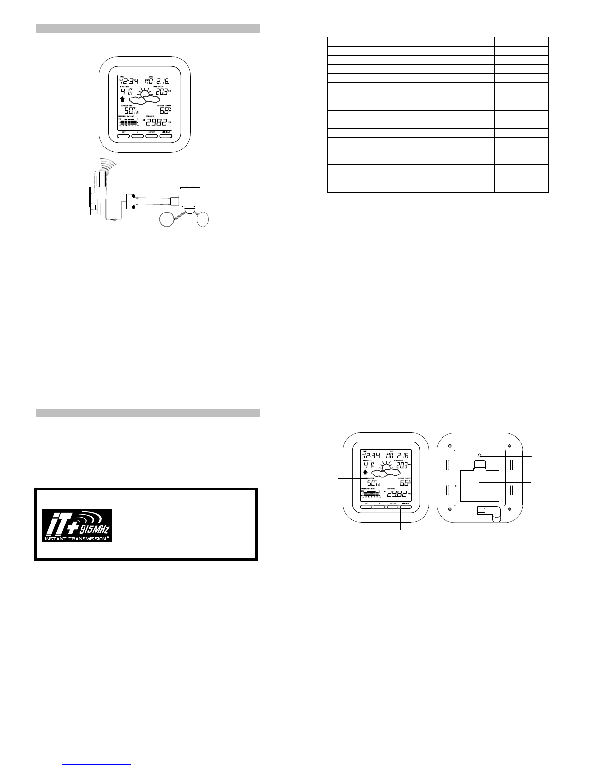
1. Wireless Weather Station
2. Wireless Thermo-hygro Sensor (TX31U-IT) and Wind Sensor (TX55U-IT) with
mounting bracket.
3. Instruction Manual
Instruction Manual
INSTANT TRANSMISSION is the state-of-the-art
new wireless transmission technology,
exclusively designed and developed by LA
CROSSE TECHNOLOGY. INSTANT
TRANSMISSION offers you an immediate update
(every 4.5 seconds!) (6.25 seconds for rain
sensor - optional) of all your outdoor data
measured from the transmitters: follow your
climatic variations in real-time!
FEATURES:
The Weather Station
LCD
Time display (manual setting)
12/24 hour time display
Calendar display (weekday , dat e, mo nt h, year)
Weather forecast icons and weather tendency indicator
Indoor temperature display in °C/ºF
Outdoor temperature display in °C/ºF
Outdoor Humidity display as RH%
Dew point displayed in ˚C or ˚F
Wind chill displayed in ˚C of ˚F
Wind gust displayed in km/h, mph or m/s
Wind speed displayed in km/h, mph or m/s
24-hour and total rainfall dis p layed in mm or inch (optional)
Display MIN/MAX value of outdoor temperature, outdoor humidity, dew point, wind
chill, and relative air pressure, with time & date of recording
Display MAX wind speed, MAX gust and MAX 24h rainfall (optional) with time &
date of recording
Relative air pressure display ed in hPa or i nH g
Air pressure tendency indicator for the past 12 hour (bargraph format)
Function keys
2
Hanging hole
Battery
compartment
cover
Foldout stand
3
4
Page 2
Manual reset of outdoo r temperature/ humidity, pressure and windchill data
s
t
-
r
r
LCD contrast selectable
Low battery indicator
Storage of 140 sets of history w eather dat a r eco r ded in 3- h ou r int er v al s
Wireless transmission at 915 MHz
Transmission range up to 330 feet/100 meters
The Thermo-hygro Tr an smi t t er
The Wind sensor
The rain sensor (optional- sold separately)
SETTING UP:
Remote transmission of the out d oo r t emp er at ur e a nd h um i dity to the
Weather Center at 915 MHz
Rain proof casing
Wall mounting case (to be mounted in a sheltered place. Avoid direct
rain and sunshine)
Connected to the thermo-hygro transmitter by
cable
Can be installed onto a mast or a horizo nt al
panel
Remote transmission of the rainfall data to the
Weather Center at 915 MHz
To be mounted onto a horizonta l pan e l
Weather center
Note:
When putting the Weather St atio n into operation, it is
important to perform in close prox im it y (e.g. on a tab le) a
complete wiring and set-up of the system. This step is
important to test all components for correct function before
placing and mounting them at their final destinations (See
Positioning below):
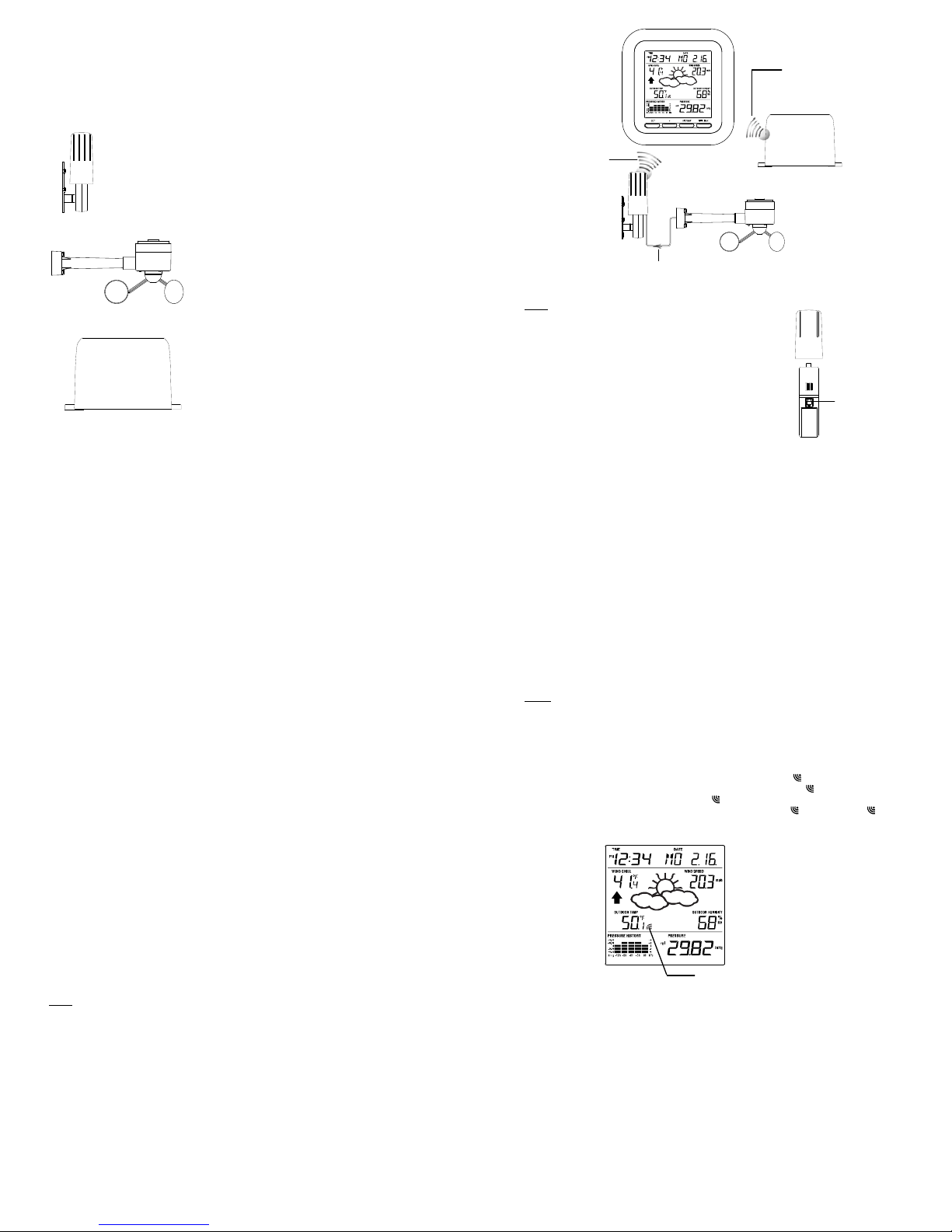
1. Unwind the cables of the Wind sensor. Connect the
Wireles
transmission a
915 MHz - thermo
hygro transmitte
to weather station
Thermo-hygro
transmitte
Cable connection between the wind sensor and
the thermo-hygro transmitter
Wind sensor to the Thermo-hygro transmitter by
plugging the connector head into the socket of the
Thermo-hygro sensor.
Rain sensor (optional)
OPTIONAL
Wireless transmission
at 915 MHz – Rain
sensor to weather
station
Wind sensor
Socket for wind
sensor
2. First insert the batteries into the The r m o-hygro sensor and Rain sensor (purch as e
separately) “How t o install and replace the batteries into the Thermo-hygro
sensor“ and “How to install and repla ce the batteries into the Rain sensor
(optional)” below).
3. Then insert the batteries into the Weather C enter (see “How to install and replace
the batteries into the Weather Center” below). Once the batteries are installed, all
segments of the LCD will light up bri ef ly . It will the n di spla y the time as 12:00, the
date as 1.1.09, the weather icons, and air pr e ss ur e value. " - - -" will be shown for
outdoor data.
4. Afterwards, the Weather Center will start rec eiving data from the transmitter. The
transmission recepti on i co n will be b lin k in g to ind ic at e that t he stat i on i s trying to get
the thermo-hygro tr ansmitter data. The outdoor temperature, humidity, wind data
should then be displayed on the Weather Center. If this does not ha pp en aft e r 13 5
seconds, the batterie s will need to be removed fr om all units. You will have to start
again from step 2.
5. The transmitter reception ic on is n ow blink in g ag ain t o in d ic at e th at th e stat i on i s
trying to get the rain sensor data. It will stop blinking once the rain sensor has been
detected. If this does not happen after 135 seconds, you will need to start again from
step 2.
6. You may need to check th e cable for correct connection and all the components for
correct function by man ually turning the wind-gauge by moving the wind-vane; tilting
the rain sensor to hear the impact of the internal moving seesaw, etc. (see
Positioning below).
7. Time and date shall be manually set (See Manual Setting below).
8. After the Weather Center has been check ed for co rr e ct fun ctio n w ith re g ard to the
above points and fou nd fit, the initial set up of the weather station system is finished
and the mounting of the system components can take place. It must be ensured
however that all components work properly together at their chosen mounting or
standing locations. If e.g. t her e a ppear to be problems with the 915 MHz radio
transmission, they can mostly be overcome by slightly changing the mounting
locations or turning the base station.
Note:
The radio communication between the receiver and the transmitters in the open field
reaches distances of max 330 feet/ 100 met er s, pr ov ided t h er e are n o inte rfe rin g ob st acl es
such as buildings, trees, vehicles, high voltage lines, etc.
5
9. Radio interferences created by PC screens, radios or TV sets can in some cases
entirely cut off radio communication. Please consider this when choosing standing or
mounting locations.
Note :
After batteries are installed in the transmitter, install the batteries in the weather
center to receive the signal from the t r an s mitt er s as s oo n as poss ible. I f t he w eat her
center is powered more than 5 hours after the transmitter is powered, the weather
center will never receive signal successfully from the transmitters. In this case, user
will need to reinstall the batteries from all the transmitters to redo set-up procedure.
After batteries are installed, there will be synchronization between Weather Center
and the transmitters. At this time, the signal reception icon
the signal is successfully received by the Weather Center, the
switched on. (If it is not successful, the
can easily see whether the last reception was successful (
off). On the other hand, the short blinking of the icon shows that a reception is in
progress.
If the signal reception is not successful on the first frequency (915MHz) for 45
seconds, the frequency is changed to 920MHz and the learning is tried another 45
seconds. If still not suc c essful, the reception is tried for 45 seconds on 910MHz. This
will also be done for re-synchronization.
6
will be blinking. When
icon will not be shown in LCD) So the user
Transmitter signal
reception icon
icon will be
icon on) or not ( icon
7
8
Page 3
y
y
A
y
r
y
r
y
HOW TO INSTALL AND REPLACE THE BATTERIES INTO THE THERMOHYGRO TRANSMITTER
Note:
In the event of changing batteri es in any of the units, all units need to be reset by following
the setting up procedures. This is because a random security code is assigned by the
thermo-hygro sensor at start-up and this code must be received and stored by the
Weather Center in the fi rst several minutes of power being supplied to it.
HOW TO INSTALL AND REPLACE THE BATTERIES INTO THE WEATHER
STATION
The outdoor Thermo-hygro tran smit t er works with 2 x AA IEC LR6,
1.5V batteries. To install and re p la ce th e bat t er i es, pl ea s e follow
the steps below:
1. Uninstall the rain cover of the transmitter.
2. Remove the battery compartment cove r.
3. Insert the batteries, observing the correct polarity (see the
marking in the battery compartm ent ).
4. Replace the battery cover and the rain cover onto the unit.
The Weather Station works with 3 x AA, IEC LR6,
1.5V batteries. When the batteries need to be
replaced, the low battery symbol will appear on
the LCD.
To install and replace the batter i es, ple a se f ol low
the steps below:
1. Remove the battery compartment cover.
2. Insert the batteries observing the correct
polarity (see the marking in the battery
compartment).
3. Replace the battery cover.
HOW TO INSTALL AND REPLACE BATTERIES INTO THE RAIN SENSOR
(OPTIONAL; SOLD SEPERATELY)
1. Unlock the main cover from the rain sensor base and remove the cover.
2. Remove the battery cover at the top of the ra in se ns or.
3. Insert 2 x AAA, IEC LR3, 1.5V batteries into the battery compartment, observin g t he
correct polarity.
4. Replace the battery cover and the main co ver o n th e unit.
Note:
In the event of changing batteri es in any of the units, all units need to be reset by following
the setting up procedures. This is because a random security code is assigned by the
transmitter and rain sensor (optional) at start-up and this code must be received and
stored by the Weather Station in the first 90 seconds of power being supplied to it.
BATTERY CHANGE:
It is recommended to replace the batteries in all units regularly to ensur e opt i m um
accuracy of these units. (Battery life –see Specifications)
Note:
The stored History record will not be kept af t er th e battery change is done on the weather
station.
FUNCTION KEYS:
Weather Station:
The Weather Station has 4 easy-to-use function keys.
Figure 1
Please participate in the preservation of the environment. Return used
batteries to an authorised depot.
Figure 2
Figure 3
SET key
Press and hold to enter manual setting modes: LCD contrast, Manual time setting,
Press to toggle between the display of Mode 1 or Mode 2:
Press to activate the reset mode when MAX or MIN record is shown
+ key
In display Mode 1, press to toggle between the display of date, weekday + date,
In display Mode 2, press to toggle between t he display of Relative Pressure, 24 hour
Press to adjust (increase) the level of different settings
Press to confirm to reset the MIN/MAX record
HISTORY key
Press to display the weather data history records
Press to exit manual setting mode
SET ke
+ ke
12/24 hour time display, Calendar setting, ºC/ ºF temperature unit, Wind speed unit,
Rainfall unit, Pressure unit, Relative pressure reference setting, Weather tendency
threshold, Storm threshold setting
Mode1: "Wind speed + outdoor t em p + r el. pr e ss ure"
Mode 2: "Gust + Dew P oint temp + rainfall data (only if there is a rain sensoroptional)"
(Mode 2 displayed will be shown for 30 seconds. Then it will return to normal display)
Indoor temp, or second
rainfall and Total rainfall (only if there is a rain sensor- optional).
9
MIN/MAX key
HISTORY key
MIN/MAX key
Press to display MIN/MAX records of various weather data
Press to adjust (decrease) the level of different settings
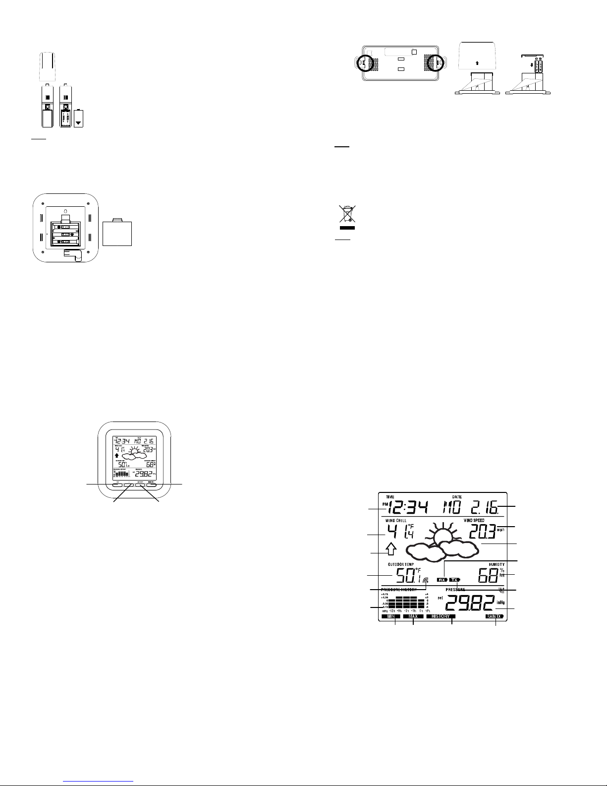
LCD SCREEN
The LCD screen is split into 3 sections di sp laying the following informatio n:
1. Time and date/ indoor temp/ second
2. Wind data, outd oor te m p erat ure and humidity, dew point, we ath er f or ec ast icon and
tendency indicator
3. Air pressure history, relative air pressure, rainfall data (optional)
Time displa
Wind Chill in
˚C or ˚F
Weather tendenc
indicato
Outdoo
temperature
/ dew point
in C or F
ir pressure
MI/MAX icons
Transmitter signal
reception icon
history histogram
# When the signal from the transmitter/ or Rain sensor (optional) is successfully received
by the Weather Station, this icon will be switched on. (If not successful, the icon will not be
shown on the LCD). User can therefore easily see whether the last reception was
successful (“ON” icon) or not (“OFF ” ico n). On th e ot her h and, the s hort blinking of the icon
shows that a reception is being don e at that ti m e.
10
HISTORY
icon
Low batter
indicator (rain
sensor - optional)
Calendar / indoor
temperature / seconds
display
Wind speed / gust* in
mph, km/h, m/s
Weather forecast
Icon
Low battery indicator
(weather station)
Outdoor relative
humidity in %
Low battery
indicator #
(transmitter)
Relative air pressure /
24 hr rainfall / Total
rainfall display* (only if
there is a rain sensor
being used)
11
12
Page 4

* In normal display mod e, user may press the SET key shortly to toggle between Mode1
r
and Mode 2 display:
Mode 1 : Wind speed, outdoor temp er atur e, re lat i v e air pr ess ur e ar e shown.
Outdoor temp
Mode 2 : Wind gust, dew point, and rainfall (optional) reading are shown.
Note: To view the rainfall data, press the + key after entering Mode 2 display.
icon
In Mode 1, this reception icon is showing the condition of the
reception of the signal from Thermo-hygro transmitter
Dew point icon
13
Wind speed icon
Rel. Air Pressure icon
Wind gust icon
Rain icon
In Mode 2, this reception icon
is showing the condition of the
reception of the signal from
Rain sensor (only if a rain
sensor is being used).
Note: if no rain sensor is used,
the reception icon will always
be displayed in Mode 2.
MANUAL SETTINGS:
The following manual settings can be changed once the SET key is pressed and hold for
about 3 seconds:
LCD contrast setting
Manual time setting
12/24 hour time display
Calendar setting
°C/ °F temperature unit setting
Wind speed unit
Rainfall unit setting
Air pressure unit setting
Relative pressure reference value setting
Weather tendency threshold value
Storm warning threshold value
LCD CONTRAST SETTING
The LCD contrast can be set within 8 l ev e ls, fr om "L CD 1" t o "LCD 8" ( def a ult s et t i ng is
LCD 5):
1. Press the SET key, the contrast level dig it w ill star t f las hi ng.
2. Use the + or MIN/MAX key to adjust the level of contrast.
3. Confirm with the SET key and enter the MANUAL TIME SETTI NG.
MANUAL TIME SETTING:
You then may manually set the time of the clock by following the steps below:
1. The hour digit will start flashing.
2. Use the + or MIN/MAX key to set the hour.
3. Press the SET key to switch to the minutes. The minut e digit will start flashing.
4. Use the + or MIN/MAX key to set the minutes (holding of the key will forward the
Hou
flashing
digit by 5).
Minutes flashing
14
Digit flashing
5. Confirm the time with the SET key and enter the 12/24 HOUR TIME DISPLAY
SETTING.
12/24 HOUR TIME DISPLAY SETTING:
The time can be set to view as 12-hour or 24-hour format. The default time display mode
is “12h”. To set to “24h” time display:
1. Use the + or MIN/MAX key to toggle the value.
2. Confirm with the SET key and enter the CALENDAR SETTING.
CALENDAR SETTING:
The date default of the Weathe r Station is 1. 1. of year 2009. The date can be set
manually by proceeding as follows.
1. The year digit starts flashing.
2. Use the + or MIN/MAX key to set the year (pressing and holding the key will forward
the digit by 5). The range runs from "00" (2000) to "99" (2099).
3. Press the SET key to confirm the year and enter t he m onth setting. The month digit
will start flashing.
4. Use the + or MIN/MAX key to set the month.
5. Press the SET key to confirm the month an d ent er t he date setting mode. The date
digit will start flashing.
6. Use the + or MIN/MAX key to set the date.
7. Confirm all calendar settings with the SET key and enter the °C/°F TEMPERATURE
UNIT SETTING.
°C/°F TEMPERATURE UNIT SETTING
Year
15
Digit flashing
"Month. Date." (for 12h time display)
"Date. Month." (for 24h time display)
Flashing
The temperature display can be selected to s how temperature data in °F or °C. (default °F)
1. The temperature unit is flashing
2. Use the + or MIN/MAX key to toggle between “°F” or “°C”.
3. Confirm with the SET key and enter the WIND SPEED UNIT SETTING
WIND SPEED UNIT SETTING
The wind speed unit can be set as mph (mile per hour), km/ h (kilo m et er per h our), or m/s
(meter per second). The default u nit is mph.
1. Use the + or MIN/MAX key to toggle between the unit “mph”, “km/h”, or “m/s”
2. Confirm with the SET key and enter the RAI NF A L L UNIT SETTING.
RAINFALL UNIT SETTING (OPTIONAL)
Note: the rain unit setting is only available if there is a rain sensor. Skip this setting
by pressing the SET key again to enter the Relative Air Pressure Unit Setting.
The total rainfall un it can be set as inch or mm. The default unit is inch.
1. Use the + or MIN/MAX key to toggle between the unit “mm” or “Inch”
2. Confirm the unit with the SET key and ent er the RELATIVE AIR PRESSURE UNIT
SETTING
RELATIVE AIR PRESSURE UNIT SETTING
The relative air pressure can be set as hP a of inH g. The d efa u lt unit is inH g.
1. Use the + or MIN/MAX key to toggle between the unit “hPa" or “inHg”
2. Confirm the unit with the SET key and ent er the RELATIVE PRESSURE
REFERENCE VALUE SETTING.
16
Flashing
Flashing
Flashing
Page 5

RELATIVE PRESSURE REFERENCE VALUE SETTING
A
Note:
The default reference pres s ure v al u e of t he bar ometer is 29.91inHg (1013 hPa) when
batteries are first inserted. For an exact measurement, it is necessary to first adjust
the barometer to your local relative air pressu re (related to elevation above sea
level). Ask for the current atmospheric pressure of your home area (Local weather service,
www, optician, calibrated in st r uments in public buildings, airport).
The relative air pressure can be manually set to another value within t he range of 27.14 to
31.90 inHg (919 to 1080 hPa) for a better reference.
1. The current relative pressure value will start flashing
2. Use the + or MIN/MAX key to increase or decreas e th e valu e. K ee p ho ldi ng t he key
will allow the value to increase faster.
3. Confirm with the SET key and enter the WEATHER TENDENCY THRESHOLD
VALUE SETTING.
Note:
This calibration facility is useful for thos e users living at various elevations above sea level,
but wanting their air pressure dis pl ay to be based on sea level elevation.
WEATHER TENDENCY THRESHOLD VALUE SETTING
You may select a defin ite switching sensitivity value, .06, .09, or .12 inHg (2-4 hPa) for the
change in the display of weather icons. This represents the "sensitivity" of the weather
Flashing
Flashing
forecast (the smaller the value selected, the more sensitive the weather forecast). The
default value is 0.09 inHg (3 hPa).
1. The threshold value will start flashing
2. Use the + or MIN/MAX key to select the value.
3. Confirm with the SET key and enter the STORM WARNING THRESHOLD VALUE
SETTING.
STORM WARNING THRESHOLD VALUE SETTING
You may also define a switching sensitivity value for the Storm warning display at a
decrease of air pressure from .09 in H g to .27 inH g (3- 9 hPa) o v er 6 hou rs (D ef au lt 0. 1 5
inHg (5 hPa)).
1. The threshold value will start flashing.
2. Use the + or MIN/MAX key to select the value.
3. Confirm with the SET key and enter the STORM ALARM ON/ OFF SETTING.
STORM ALARM ON/ OFF SETTING
Note: the storm alarm ON/OFF setting is not available on this model. Skip and exit
this setting by pressing the SET key.
TO EXIT THE MANUAL SETTING MODE
To exit the manual setting any time d ur in g the ma nu a l set ti ng m o des, pre ss th e HIST O RY
key anytime or wait for the automatic timeout. The mode will return to the normal time
display.
WEATHER FORECAST AND WEATHER TENDENCY
WEATHER FORECASTING ICONS
Weather icons in the third section of L CD can b e displayed in any of the following
combinations:
Flashing
For every sudden or significant change in the air pressure, the weather icons will update
accordingly to represent the change in weather. If the icons do not change, then it means
either the air pressure has not change d or the ch an ge ha s bee n too slow for the Weather
station to register. However, if the ico n di sp layed is a sun or raining cloud, there will be no
change of icon if the weather gets any better (w ith sunny icon) or worse (with rainy icon)
since the icons are already at t heir ext re me s.
The icons displayed forecasts the weather in terms of getting better or w orse and n ot
necessarily sunny or rainy as each icon indicates. For example, if the current weather is
cloudy and the rainy icon is displayed, it does not mean that the product is faulty because
it is not raining. It simply means that the air pr ess ur e has dr opp e d and t he w eather is
expected to get worse but not neces sar i ly rainy .
Note:
After setting up, readings for weat her f ore c asts sh ou ld be di sr eg ar d ed for th e next 48- 60
hours. This will allow sufficient time for the Weather station to collect air pressure data at a
constant altitude and theref or e r esult in a more accurate forecast.
Common to weather forecasting, absolute accur acy cannot be guaranteed. The weather
forecasting feature is estimated to have an accuracy level of about 75% due to the varying
areas the Weather station has been designed for use. In areas that experience sudden
changes in weather (for example from sunny to rain), the Weather station will be more
accurate compared to use in areas where the weather is stagnant most of the time (for
example mostly sunny).
If the Weather station is moved to another location significantly higher or lower than its
initial standing point (for example from the ground floor to the upper floors of a house),
discard the weather forecast for the n ext 48- 6 0 ho urs. By doing this, the Weather Station
will not mistake the new location as being a possible change in air-pressure when really it
is due to the slight c hange of altitude.
WEATHER TENDENCY INDICATOR
Working together with the weather icons is the weather tendency indicators (located on the
left and right sides of t he weather icons). When th e indicator points upwards, it means that
Sunny
Cloudy with sunny intervals
17
Rainy
the air-pressure is increa si ng a nd the weather is expected to improve, but w hen in di c at or
points downwards, the air-pressure is dropping and the weather is expected to become
worse.
Taking this into account, one ca n see h ow the weather has changed and is expected t o
change. For example, if the indicator is pointing downwards together with cloud and sun
icons, then the last noticeab l e chan ge i n th e weather was when it was sunny (the sun icon
only). Therefore, the next change in the weather will be cloud with rain icons since the
indicator is pointing downw ards.
Note:
Once the weather tendency indic at or has r egi st ere d a cha ng e in air pre ssu r e, it w ill re mai n
permanently visualized on the LCD.
AIR PRESSURE HISTORY (ELECTRONIC BAROMETER WITH
BAROMETRIC PRESSURE TREND)
The bottom section of the LCD also shows the relative air pressure value and the air
pressure history.
Depending on programming conditions, display of the history of air pressure in form of a
graph consisting of vertical bar s.
The bar graph of the electronic bar om et er shows the air pressure history of the past 12
hours in five 3-hour steps.
The horizontal axis represent s th e la st 12 ho urs a ir pr ess ur e rec or ding (- 12, -9, - 6, -3 and
0 hour). The bars are plotted at eac h of the 5 st eps and gi v e the t r en d over the re cor d ed
period. The scale on the right compares the result. The "0" in the middle of this scale
determines the current air pr ess ure.
The vertical axis represents the air pressure changes in inHg (+0.12, +0.06, 0, -0.06, -0.12.
The “0” represents the current air pre s sur e). T he n ewly measured pressure was compar ed
to the previously recorded pr es sure reading. The pressure chang e is expr e ss e d by the
difference between the curr ent (" 0 h") and t he past rea din gs in di vi s ion of ±2 h Pa or ±0. 0 6
inHg. If the bars are rising it indicates t h at th e weather is getting better due to an incre ase
in air pressure. If the bars go down it ind ic at es a drop of the a ir pr es s ur e and t he w eather
ir pressure
changes in inHg
18
Air pressure
changes in hPa
19
20
Page 6

is expected to get worse from the present time "0".
r
t
At every full hour, the current air pressure is used as a basis for the display of a new graph
bar. The existing graph is then move d one co lu mn to th e left .
Note:
For accurate barometric pressure trend, the Weather Cent er s hou ld o per at e at the same
altitude. For example, it shoul d not b e mo v ed. Sho u ld th e un it be mov ed, f or inst an c e fr om
the ground to the second floor of the hou s e, th e rea din gs f or the n e xt 48- 60 ho ur s sha ll be
discarded.
WIND SPEED MEASUREMENT
In normal display mode, the secon d se cti on of the L CD s h ow s the foll owing wind data.
Wind chill in F or C
Wind Speed in km/h, mph or m/s
Gust in km/h, mph or m/s (displayed when in Mode 2, by pressing the SET key
shortly)
Wind chill
RAINFALL MEASUREMENT (OPTIONAL)
The total rainfall and 24 hour rai nf al l meas ur e me nt is di sp layed in the last section of the
LCD, in the unit of mm or inch.
To View the 24-hour rainfall or the Total rainfall reading:
1. In normal display, press SET key once and the display will shift to Mode 2.
2. Press + key consecutively key to tog gle between the 24-hour rainfall, Tot a l rai nf al l
and Rel. pressure reading.
Wind speed or Gust will
be shown
VIEWING THE HISTORY DATA
The weather station can store up to 140 sets of weather data which are recorded
automatically at 3-h our intervals after the weather station is powered up, at the nearest
time of 0:00, 03:00, 06:00, 09: 00, 12: 0 0, 15: 0 0, 1 8:00 a nd 21:00. For instance, if user has
manually set the time as 14:52 aft er inst al li ng b at ter ie s, the fir st hist ory record will be
made at the coming 15:00 automatically. Then the second record will be on 18:00 and so
on.
Each weather record includes the Wind direction, Wind speed/ gust in Beaufort scale,
Wind chill temperature, wind speed/gust, dew point, Outdoor temp and humidity, relative
pressure, 24-hour rainfall and total rainfall, pressure history and weather tendency. Also,
the time and date of recording w ill be displayed.
Note:
In order to acquire the correct time of re c ord in g of th e hi story records, you shall manually
set the current time as soon as installin g bat ter i es t o the weather station. Afterwards, y ou
should avoid changing the pre- set t ime as it w ill also alter the recorded "time of recording"
of each history record, whic h may lead to confusion.
To view the weather history :
1. In normal display, press the HISTORY key. The latest weather record will be shown
with the date and time of recordin g. Th e "HI ST O RY " icon will be displayed at the
bottom of the LCD.
2. When viewing History records, user may shift to see the Mode 1 or Mode 2 data by
pressing the SET key.
Mode 1: with wind speed + outdoor Temp + Rel. pressure;
Mode 2 : with wind gust + Dew point + rainfall data (optional)
24 hour rainfall icon
24 hour rainfall amount
Total rainfall icon
Total rainfall amount
Note: To view total rainfall or 24-hour rainfall in history records, first, in normal display
mode, choose to show the particular rainfall data, then press the History key followed by
the SET key to view the particular rainfall data in History records. (rain dat a information
only available if a rain sensor is being used- optional).
3. When viewing History records, press MIN/ MAX to view older records.
(Press MIN/MAX and + key to view "Previous" and "Next" record respectively. The
records are made at 3-hour interval s)
Note:
The stored history records will not be retained after battery change or whenever
battery is removed.
The total rainfall value will be exhibited in whole number (no decimal place) in the
history record.
VIEWING THE MAXIMUM/ MINIMUM WEATHER DATA
The weather station w ill record the maximum and minimum value of the various weather
data with time and date of record ing automatically. The follow ing st or ed m ax i mu m and
minimum weather data can be viewed by pres sing the MIN/MAX key in normal display
mode.
21
HISTORY icon
1. MIN outdoor temperature with the date and time of recording
2. MAX outdoor temperature with the date and time of recording
3. MIN dew point temperature
4. MAX dew point temperature
5. MIN outdoor humidity with the date and time of recording
Time and date
or recording
MIN outdoo
temperature value
MIN icon
Time and date
or recording
MIN Dew Poin
temp
MIN icon
22
23
24
Page 7

r
6. MAX outdoor humidity with the date and time of recording
7. MIN Wind chill temperature with the date and time of recording
8. MAX Wind chill temperature with the date and time of recording
9. MIN Relative pressure with the date and time of recording
MIN icon
Time and date
or recording
MIN wind chill
value
MIN icon
Time and date
or recording
MIN outdoor
humidity value
10. MAX Relative pressure with the date and time of recording
MAX icon
11. MAX wind speed with the date and time of recording
MAX icon
Time and date
or recording
MAX relative
pressure value
MAX wind
speed value
Time and date
or recording
12. MAX Gust with the date and time of recording
MAX icon
13. MAX 24 hour rainfall (optional) with the date and time of recording
RESET THE MAXIMUM AND MINIMUM WEATHER DATA
To reset the aforementione d m ax im um or mi ni mu m w eat h er dat a 1. to 13. , y ou sha ll nee d
to reset each of the data independently.
24 hou
rainfall icon
25
Time and date
or recording
MAX Gust value
The 24h rainfall value
is counted from this
time and date
24h rainfall
amount
1. Press MIN/MAX key t o show the desired weather d ata. For instance, if you want to
reset the minimum humidity, in the norm a l display you shall press the MIN/MAX key
three times to show the min humidity value.
2. Press and hold the SET key for about 2 seconds, then th e "RESET" icon will appear
at the bottom part of the LCD.
3. Press the + key once, then the stored val ue w i ll be res et to the current value and
current time.
4. Press the HISTORY key to return to normal displ ay mode.
10. Total rainfall amount (optional) with the date and time of recording
The total rainfall measurement is displayed in the last section of t he LCD, in the unit of mm
or inch. It shows the total rainfall accu mu lat e d sin ce l ast res et of the weather station.
In normal display mode, press the MIN/MAX key fourteen times to show the total rainfall
value. The "RESET" icon w ill also be shown at the same t ime.
To reset the rainfall reading, press the + key once when the Rainfall value and "Reset"
icon is shown. Then the total rainf al l am ount w ill be r eset t o 0, and th e time u pd at ed t o
current time.
Note:
After power up, the time and date and tot al ra inf a ll are d isplayed as "- - -". After time is
adjusted manually, the set time will be shown.
26
The total rainfall value is
counted from this time and
date
Total rainfall icon
Total rainfall
amount
27
28
Page 8

LOW BATTERY INDICATOR
r
t
The low battery indicator of the weather station and the transmitter will be displayed at the
second section, and the low battery icon for the rain sensor (optional) will be display on the
last section of the LC D respectively when the battery power is low. It is recommended to
replace the batteries in all units on an annual basis to ensure optimum accuracy of the
system.
Note:
After battery change, both the Weather Station and the transmitters need to be reset
(see note ”Setting up”)
The History data record will be clear after the battery change.
OUTDOOR TRANSMITTER 915 MHz RECEPTI ON CHECK
The outdoor temperature, h umi dity, wind data are transmitted fr o m ther m o- hy gr o
transmitter every 4.5 secon ds; th e rai nf al l dat a are t ran s mit t ed fr om t he ra in se ns or
(optional) every 6. 25 seconds. The receiver will be synchronized t o the thermo-hygro
transmitter and rain sensor (optional) then. The transmission range (supposedly up to
about 330 feet /100 meters) of the therm o- hy gro tr a nsmit t er/ ra in sens or m ay be aff ect e d
by the ambient temp er ature. At cold temperatures, the transmitting distance may be
decreased. Please keep this in mind when placing the transmitter and the rain sensor.
If (1) the outdoor data are not being recei ve d w ithi n fir st sev er al m in ut es aft er sett i ng up;
(2) the outdoor display always show “- - -“ on the outdoor display; or (3) the reception icon
of thermo-hygro transmit ter ( Mo de 1) a nd r ai n se nso r (o ptio na l ) (Mo de 2) is not dis p layed
on the display, user shall check the following points:
1. The distance of the Weather Station or tra ns mitt e r/ rai n se n sor shou ld b e at le a st 5
to 6.5 feet (1.5 to 2 meters) away from any interfering sources such as computer
monitors or TV sets.
2. Avoid positioning t he Weather Center onto or in the immediate proximity of metal
doors or window frames.
3. Using other electrical produ cts s uc h as headp h on es or sp ea k ers op erating on the
same signal frequency (915 MHz) may prevent correct signal transmission and
reception.
4. Neighbors using electrical de vi c es oper at i ng o n the 91 5 MHz si gnal fr eq ue n cy can
also cause interference.
5. “Visibility” of weather center and transmitters increases the range
Note:
When the 915 MHz signal is received, do not re-open the battery compartment cover of
either the transmitter/ rain sensor or Weather station, as the batter ies may spring free from
the contacts and force a false reset. Shou ld t his ha pp e n acci d ent a lly then reset all units
(see Setting up above) otherwise transmission problems may occur.
During normal operation, after the outdoor display shows "- - -", the weather station will
change to receive the outdoor data every 15 minutes, until the data is read. Then the
reception period for thermo-hygro transmitter will return to 4.5 secon ds (6.25 seconds for
rain sensor - optional).
If no reception is possible despit e the o bs er vation of these factors, all system un it s have t o
be reset (see Setting up).
POSITIONING:
Prior to permanently affixing any of the units, please ensure the following points are
considered:
Cable lengths of the units meet with your distance requirements at the point of fixing
Signals from the sensors can be received by the base station at points of mounting
La Crosse Technology Sensor Extension Cable
You can purchase a La Crosse Technology Extension Cable if you require additional
length to properly mount your s en sor. The extension cable is 32 feet in lengt h and co m es
with the appropriate connecter attached. Please visit your local retailer or
www.lacrossetechnology.com
other retailers.
Using phone cables or connections may damage your sensors because phone cables and
connections have more res ist a n ce tha n t h e La Cro sse T ec h no logy phone extension cable.
Phone cables or connections are not recommended for use.
Note: Using extension cables will shorten battery life.
Warning: Never cut, splice, shorten or modify your sensor cables or extension cables.
Doing so may damage your sensors and will void your warranty.
The Weather Station
The Weather Station has been des ign ed to be hung onto wall or free standing wit h the two
kinds of foldout stand.
and click on the Buy button to locate an online dealer or
To wall mount
The Thermo-hygro Sensor
An ideal mounting place for the th er mo- hygro sensor would be the outer wall b ene at h the
extension of a roof, as this will protect the sensor from direct sunlight and other extreme
weather conditions.
To wall mount, use the 2 screws to affix the wall bracket to the desired wall, plug in the
thermo-hygro sensor to the bra cket a n d secure b ot h part s by the use of the sup pl ied scr ew
and ensure that the cables from the wind and rain sensors are correctly plugged in
otherwise data transmission errors could occur.
Choose a sheltered place. Avoi d dir ect rain an d s un s hi ne.
Before wall mounting, pleas e check t hat the o ut do or te mper ature
and humidity values can be receiv ed from the desired locations. To
wall mount:
1. Fix a screw (not supplied) into the desired wall, leaving the
head extended out the by about 5m m.
2. Hang the station onto t he screw. Remember to ensure that it
locks into place before releasing.
Rain Cove
Main Uni
29
Wall Bracket
The Wind Sensor
Firstly, check that the wind-cups can rotate freely before fixing the unit. For correct and
accurate readings, it is important to mount the sensor so that the front (marked E) is
pointing in East-West direction. The wind sensor should now be mounted using the screw
or cable tie provided onto a solid wall/ panel mast or mast to allow the wind to travel
around the sensor unhindered from all directions (ideal mast size should be from diameter
0.62” to 1.29” (16mm to 33mm). Do not over tighten.
Once the wind sensor is fixed onto the mast, connect the cable to the corresponding
thermo-hygro sensor socket so that operatin g power supply can be re ceived and data can
be transmitted to the base station. Secure cor d from blowing. Do not use staples. Using
PVC pipe or metal as a mast may cause static. Wood is recommended.
The Rain Sensor (optional)
Wind -cups
Horizontal panel
30
Horizontal panel
Vertical
mast
31
32
Page 9

For best results, the rain sensor sho uld b e sec ure ly mounted onto a horizontal surface
about 39.37” (1 meter) above the gr ou n d (or hi gh er) and in a n op en ar e a aw ay from tr ees
or other coverings where rainfall may be reduced causing inaccurate readings.
When securing into place, check that r ai n exc es s w ill not co ll ect and st or e at the b ase of
the unit but can flow out between the base a nd the mounting surface (test by pouring
clean water).
After mounting the rain sensor an d pl ac ing b at tery, the rain sensor is now operable. For
testing purposes, very slow ly pour a sm a ll am o unt of clean w at er into the rain sensor
funnel. The water will act as rainfall and will be received and displayed at t he base station
i.e. when the reading interva l is re ac he d.
CARE AND MAINTENANCE:
Extreme temperatures, vibration and shock should be avoi d ed a s th es e may cau s e
damage to the unit and give inaccurat e foreca sts a nd re ad in gs .
Precautions shall be taken when handling the batteries. Inj urie s, bur ns, or pr o pert y
damage may be resulted if the batteries are in contact with conducting materials,
heat, corrosive materials or exp lo s iv es . The batt er i es s ha ll be ta ken out f ro m the un it
before the product is to be stored for a long period of time.
Immediately remove all low powered batteries to avoid leak ag e a nd dam a ge.
Replace only with new batteries of the recommended type.
When cleaning the di splay and casings, use a soft damp cloth only. Do not use
solvents or scouring agents as they may mark the LCD and casings.
Do not submerge the unit in water.
Special care shall be taken when handling a damaged LCD dis play. The liquid
crystals can be harmful to user's health.
Do not make any repair attempts to the unit. Return them to their original point of
purchase for repair by a qualified engineer. O pening and tampering with the unit may
invalidate their guarantee.
Never touch the exposed electronic circuit of the device as th er e is a dange r of
electric shock should it beco me ex pos ed.
Do not expose the units to extreme and sudden temperature changes, this may lead
to rapid changes in forecasts and readings and thereby reduce their accuracy.
SPECIFICATIONS:
Temperature measurin g rang e :
Indoor : 32°F to +139.8°F with 0.2°F resolution
0ºC to +59.9ºC with 0.1ºC resolution
(“OF.L” displayed if outsid e this range)
Outdoor / dew point : -40°F to +139.8°F with 0.2°F resolution
-40ºC to +59.9ºC with 0.1ºC resolution
(“OF.L” displayed if outside this range)
Relative humidity measuring range:
Outdoor : 1% to 99% with 1% resolution
(“- -” displayed if < 1%, "99" displayed if 99%)
Wind speed/ gust : 0 to 111.8 mph (0 to 180km/h; 0 to 50 m/s)
(displayed "OF.L" when > 111.8 mph; 180 km/h; 50m/s)
Wind chill/ dew point: -40°F to +139.8°F with 0.2°F resolution
-40ºC to +59.9ºC with 0.1ºC resolution
(“OF.L” displayed if outside this range)
Relative pressure pre-set range : 27.14 to 31.90 inHg (919 to 1080 hPa)
24h rainfall : 0" to 39.3" with 0.01” re so lut i on
0 to 999.9 mm with 0.1mm resolution
Total rainfall : 0" to 393.7" with 0.01” resolution
0 to 9999 mm with 0.1mm resolution
(displayed "OF.L" when > 9999mm)
(When the total rainfall is higher than 1000mm (for mm
Outdoor data reception : every 4.5 seconds (from thermo-hygro transmitter)
every 6.25 seconds (from rain sensor-optional)
Air pressure checking interval: every 15 seconds
Transmission range : up to 330 feet (100 meters) in open space
Power consumption:
Weather Center : 3 x AA, IEC LR6, 1.5V
Thermo-hygro transmitter : 2 x AA, IEC LR6, 1.5V
Rain sensor(optional) : 2 x AAA, IEC LR3, 1.5V
Battery life : approximately 24 mo nt hs (A lkal in e batteries
Dimensions (L x W x H):
Weather Center : 5.33” x 1.1” x 5.56” / 135.4 x 28 mm x 141.4mm
Thermo-hygro transmitter : 2.25” x 2.44” x 6.17” / 57.3 x 62 x 157mm
Wind sensor : 9.8” x 5.7” x 7.5” / 250 x 145.9 x 191.4mm
unit only), the resolution is changed to 1mm)
recommended)
Rain sensor (optional) : 5.67” x 2.15” x3.46” / 144 x 54.6 x 88mm
LIABILITY DISCLAIMER
The electrical and electronic wastes contain hazardous substances. Disposal of
electronic waste in wild country and/or in unauthorized grounds strongly damages
the environment.
Please contact your local or/and regional authorities to retrieve the addresses of
legal dumping grounds with sele ct iv e col le ct io n.
All electronic instruments must from now on be r ecycled. User shall take an active
part in the reuse, recycling and reco v ery of the electrical and electronic wast e.
The unrestricted disposal of electronic waste may do har m on publ ic h ea lt h an d t he
quality of environment.
As stated on the gift box and labeled on the product, reading the “User manual” is
highly recommended for the benefit of the user. This product must however not be
thrown in general rubbish collection points.
The manufacturer and supplier cannot accept any responsibility for any incorrect
readings and any cons equences that occur shou ld an inaccurate readi ng take place.
This product is designed for use in the home only as indication of th e temp er ature.
This product is not to be used for medical purposes or for public information.
The specifications of this product may cha nge without prior notice.
This product is not a toy. Keep out of the reach of children.
No part of this manual may be reproduced without written authorization of the
manufacturer.
WARRANTY INFORMATION
La Crosse Technology, Ltd pro vi d es a 1-y ear l im it ed w arr a nty on this pr o duct against
manufacturing defects in materials and workmanship.
This limited warranty begins on the original date of purchase, is valid only on products
purchased and used in North Amer i ca a nd o nly to the original purchaser of this pro du ct .
To receive warranty service, the purchaser must cont act La Crosse Technology, Ltd for
problem determinatio n an d serv ic e pr oc e dur e s. Warrant y service can only be performed
by a La Crosse Technology, Ltd authorized service center. The original dated bill of sale
must be presented upon request as pr oof of pur c ha s e to La Cr oss e T ech nol o gy , Ltd or La
Crosse Technology, Ltd’s authorized service center.
La Crosse Technology, Ltd will repair or replace this product, at our option and at no
charge as stipulated here in, with new or reconditioned parts or prod u ct s if fou n d to be
defective during the limited warranty period specified above. All replaced parts and
products become the property of La Crosse Technology, Ltd and must be returned to La
33
Crosse Technology, Ltd. Replacement parts and products assume the remaining original
warranty, or ninety (90) days, whichever is long er. La Crosse Technology, Ltd will pay all
expenses for labor and materials for all repairs covered by this warranty. If necessary
repairs are not covered by this w arr an ty, or if a product is examined which is not in need or
repair, you will be char ged for the repairs or exa mination. The owner must pay any
shipping charges incurre d in g ett in g y our L a Cr oss e Tec hn ol ogy, Ltd product to a La
Crosse Technology, Ltd authorized service center. La Crosse Technology, Ltd will pay
ground return shipping charges to the owner of the product to a USA address only.
Your La Crosse Technology, Ltd warranty covers all defects in material and workmanship
with the following specified exceptions: (1) damage caused by accident, unreasonable use
or neglect (including the lack of re as on abl e an d nec ess ary ma int en an ce ); (2) da m a ge
occurring during shipment (cla im s must be pr ese nt ed to t he carr ier); ( 3) dam ag e to, or
deterioration of, any accessory or decorative s ur face; (4) damage result ing from failure to
follow instructions contained in your owner’s manual; (5) damage resu lting from the
performance of repairs or alterati on s b y someon e oth er th an an aut h or iz ed L a Cross e
Technology, Ltd authorized service center; (6) units used for other th an home use (7)
applications and uses that this pr oduct was not intended or (8) the products inabil ity to
receive a signal due to any source of interference.. This warranty covers only actual
defects within the product itself, and does not cover the cost of installation or removal from
a fixed installation, normal s et- u p or adju stm e nts, cl aims ba s ed o n misr e pr es ent at io n by
the seller or performance variati o ns re s ult in g from installation-related circums t a nces.
LA CROSSE TECHNOLOGY, LTD WILL NOT ASSUME LIABILITY FOR INCIDENTAL,
CONSEQUENTIAL , PUNITIVE, OR OTHER SIMILAR DAMAGES ASSOCIATED WITH
THE OPERATION OR MALFUNCTION OF THIS PRODUCT. THIS PRODUCT IS NOT
TO BE USED FOR MEDICAL PURPOSES OR FOR P UBLIC INFORMATION. THIS
PRODUCT IS NOT A TOY. KEEP OUT OF CHILDREN’S REACH.
This warranty gives you specific legal rights. You may also have other rights specific to
your State. Some States do no allow the exc lu s io n of con se q uential or incidental
damages therefore the abov e ex c lus ion of limitation may not apply to y ou.
For warranty work, technical support, or information contact:
La Crosse Technology, Ltd
34
2809 Losey Blvd. S.
La Crosse, WI 54601
Phone: 608.782.1610
Fax: 608.796.1020
35
36
Page 10

support@lacrossetechnology.com
sales@lacrossetechnology.com
(information on other product s )
www.lacrossetechnology.com
For more information, please visit:
www.lacrossetechnology.com/1910
All rights reserved. This handbook must not be reproduced in any form, even in excerpts, or duplicated or
processed using electronic, mechanical or chemical procedures without written permission of the
publisher.
This handbook may contain mistakes and printing errors. The information in this handbook is regularly
checked and corrections made in the next issue. We accept no liability for technical mistakes or printing
errors, or their consequences.
All trademarks and patents are acknowledged.
e-mail:
(warranty work)
web:
37
 Loading...