

Page 1
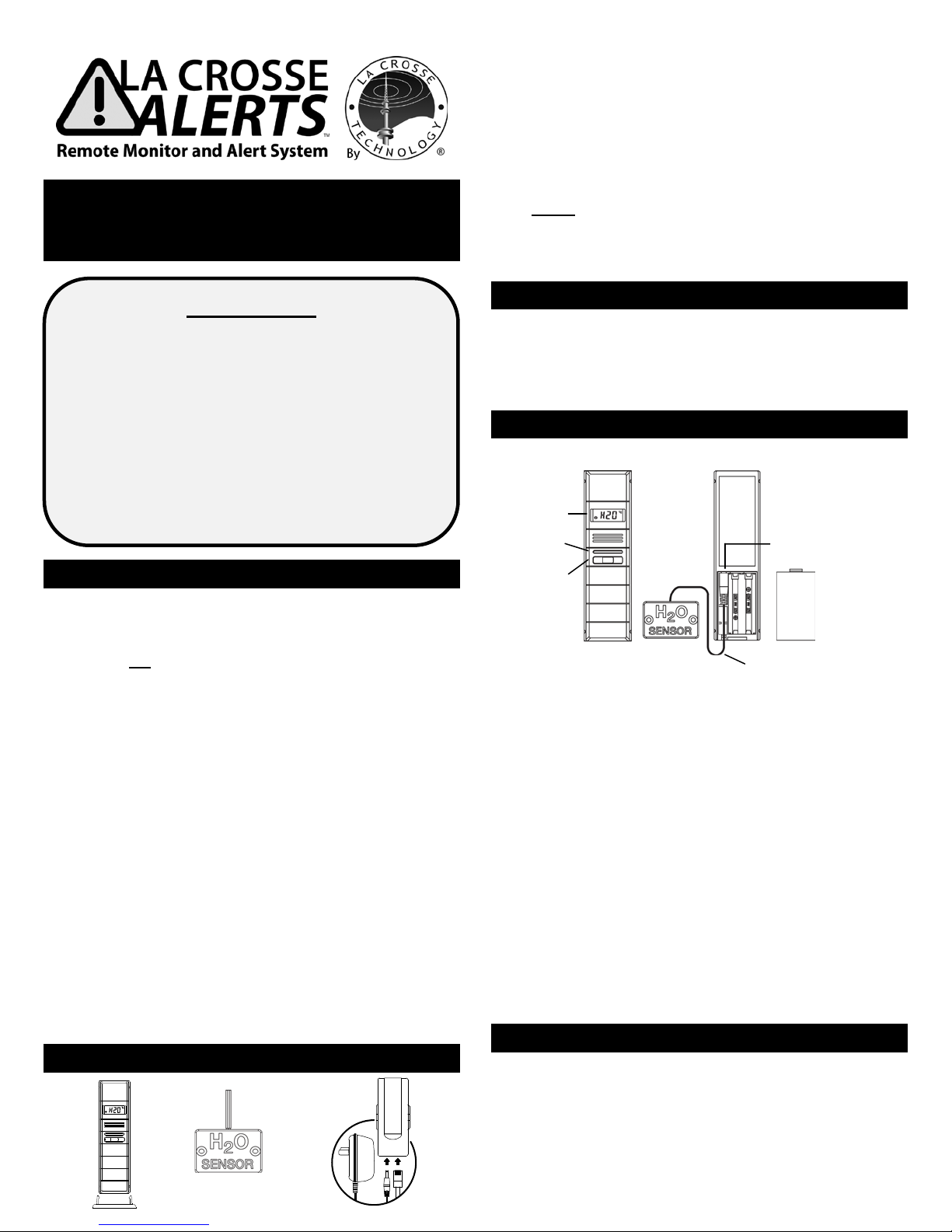
This socket is ONLY
for the
DO NOT insert
power plug
**H2O sensor with
LCD
Button
(B)
(A)
(1)
(2)
(3)
PRODUCT OVERVIEW GUIDE
WIRELESS REMOTE WATER DETECTOR
WITH TEMP. & HUMIDITY MONITOR
Model: D112.104.E1.BP
IMPORTANT
This document provides general product information and
specifications. Please visit www.lacrossealerts.com for
complete set up a nd activation instructions.
Fir st, create an a cco unt at www.lacrossealerts.com. Once
you have an account, choose model TX70U-IT on the we bsite
to begin the set up process with step-by-step instructions.
Enter the key from the ACTI V ATION KEY CARD (included in
the package) when prompted by the website.
Need help? Visit:
www.lacrossetechnology.com/support/alerts
GENERAL USE AND APPLICATIONS
Insurance companies sit e water damage from faulty pl umbing
& frozen pipes as the third mos t com mon ca use o f homeowner
claims. While you can’t predict w ater l eaks or mechanical
failure, you can improve your response time with a La Crosse
Alerts™ Remote Monitor with Early Warning Alerts to help
you protect your property and minimize repair costs.*
Use your smartphone, tablet or computer to monitor for water
leaks and high or low temperature/humidity levels to prevent
frozen pipes or mol d growth. * Water damage can be caused by
frozen or broken pipes, rusty w ater heaters, leaky roofs,
basements and foundations from snow, rain or floods, faulty
plumbing installation, sump pump overf l ow, leaky dishwasher
hoses and washing machine overflow.*
Monitor and protect property: Connect the included gateway to
your existing network router, and register your remote monitor
on www.lacrossealerts.com to activate remote monitoring
with tex t an d e-m ail alerts.*
MONITORING APPLICATIONS
• Hom e, secon d hom e, office or rental property
• Kitchens, baths, laundry & pool rooms
• Uti l it y sinks, sumps & water hea ters
• Basements, garages, attics, greenhous es & f ar ms
• Near aquariums & terrariums
PACKAGE CONTENTS
HARDWARE:
1. Wireless Remote Water Detec tor w ith Temp.& Humidity
Monitor and mount ing brac ket (TX70U-IT)
2. H20 (water) sensor on 6 Ft. detachable cable (D000.104)
that detects WET (H20) or DRY (DRY) conditions.
3. Intern et Gate way wit h brac ket, AC adapter and LAN cable
4. Mounting hardware ( screw s an d dryw all a ncho r s)
PRINTED MATERIALS:
5. Printed Product Overview Guide (this document)
NOTE: Set up a nd activatio n inst ructi ons are onl ine:
www.lacrossealerts.com
6. IMPORTANT: Activation Key Card for
set up and activation. Do not throw away.
ADDITIONAL EQUIPMENT (NOT INCLUDED)
• Two fresh AAA, IEC LR03, 1.5V Alkaline batteries
• Two-sided tape as need ed
• Browser with hi gh speed Internet
• Network router
FEATURES AND MEASUREMENTS (Diagram 1)
water sensor.
LED
into it.
6-foot wire to plug into sensor
(A) Wireless Remote W ater Detector with Temp./Humidity:
• LCD displays ambient air t emp. & humidity
• LCD displays water status: W ET (H20) or DRY
• Transmits coll ected data to Internet Gateway
within a 200 Ft. wireless range.
• Weather resistant cas e ( not w ater proof)
Note: The case with LCD cannot get wet and may
be affected by high humidity conditions.
• Wall hanging or free standing
(B) H20 Water Sensor on 6 Ft. Detachable Cable:
• H20 sensor detects the presence or absence of water
• ** At tach it to the w ater detector case a nd place the
sensor on the f loor or other area you wish to monit or
for WET/DRY conditions.
• **The official D000.104 H20 Sensor can be plugged
into the sensor at any time without resetting.
HOW IT WORKS
• The wir eless sensor monitors wet/dry conditions and
temperature/humidity; it sends the data to the Internet
Gat eway within a 200 Ft. (60.96m) wi rel ess range.*
• Connect the Internet Gateway to your network router with
the included LAN cable. The Gatew ay us es yo ur hi gh
speed Internet connection to send the d ata to your own
Page 2
account on www.lacrossealerts.com which you will
create using your preferred e-mail addr ess.*
• Once you register and activate the sensor and gateway,
you can monitor sensor(s) online from your Internetenabled smartphone, tablet or computer , and receive
custom e-mail / text alerts*.
• Add up to 5 sensors (sold separately) per gateway to
monitor other areas.
PREPARE FORSETUP
1. Begin set up near your existing network router and a
computer with high-speed Internet a ccess.
2. Unpack package contents and insert the H2O sensor cord
into the TX70U-IT water d etector (see dia gram 1) .
SETUP AND ACTIVATION
1. Locate the Activation Key Card in the package for setup
instructions and the Activation Key. The Act ivati on Key i s
necessary to activate your sensor and Internet Gateway.
Please keep your Activation Card for reference.
2. Visit www.lacrossealerts.com with your A ct ivatio n Key
Card to create your account and activate the product.
ACTIVATION INFORMATION:
THE INCLUDED ACT IVATION KEY is good for
1 year of ENHANCED SERVICE wit h earl y warni ng text
& e-mail alerts, plus 4 more years of BASIC SERVICE
for standard remote monitoring.
Lost your Activation Key Card?
Contact Customer Support:
www.lacrossetechnology.com/support/alerts
Phone: (608) 785-7920
MEASUREMENT LOG DOWNLOAD
Once the sensor is activat ed an d buildi ng a mea suremen t log,
you can download the data as a comma separated values
(CSV) file. You must use an application such as Microsoft
Excel® or Google Docs® that supports comma separated
values ( CSV) formatted fi les t o view the t able dat a.
SELECT A LOCATION TO MOUNT WATER DETECTOR
• Select a locati on pr otected f rom water and other
precipit at ion. The case is water resi stant, not water p roof.
• Place the sensor in a dry, shaded area. Avoid locations with
direct sun, to prevent inacc urate readings.
• Fog and mist will not harm the sensor but direct precipit atio n
must be avoided.
• Note: Exposing the sensor case to extreme humidity may
temporarily disr upt data. The sensor ca se reads h umi di ty,
but should not be submerged in water.
• Attach the H20 ca ble senso r to the Rem ote Water D etector
case and place it on the floor for water monitoring. Secure
the Remote Water Detector ca se in an area th at is protected
from water. Once activated, you can view the te mperature /
humidity and H2O/Dry readings on the LCD.
• The H20 sensor on 6 ft. cable is not for use in a pool or hot
tub where chemicals may cause malfunction.
• Select a location within range of the Internet Gateway
(see “IMPORTANT SETUP & OPERATION NOTES”).
CONFIRM CONNECTION BEFORE MOUNTING
• IMPORTANT: Before permanently mounting…Test sensor
in the desired mounting location for at least 1 hour to
confirm good reception. Confirm consistent readings on your
account at www.lacrossealerts.com before permanently
mounting. Move the sensor closer to the Internet
Gateway if the signal is lost or not
received.
• Mount the sensor after the activation
process
(see “SETUP AND ACTIVATION”).
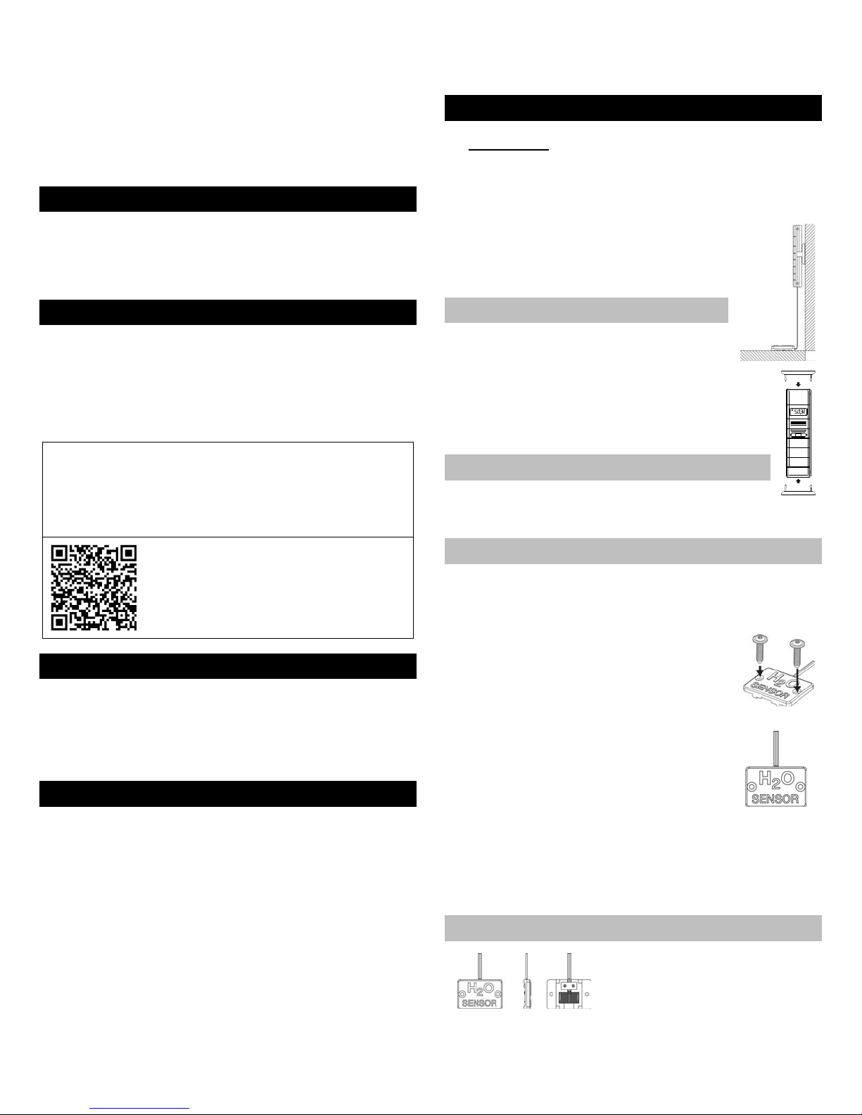
MOUNT TO WALL WITH SCREWS
1. Remove the mounting bracket
2. Place bracket over the desired location.
3. Mark mounting surface with a pencil through the
2 holes o f t he brack et.
4. Screw bracket o nto surface an d
tight en screws t o bracket.
5. Insert t he sensor back into the bracket.
FREE STANDING
Attach the mounting bracket to the bottom or
top of the sensor and place it o n any fl at surf ace.
PLACEMENT OF THE H2O SENSOR
The H2O sensor should be placed on the dry floor or against
the wall near your foundation, water heater, sump, plumbing,
was her a quarium, or dish wash er etc . to mo nit or for leaks.
FLOOR:
Place the H2O sensor (circuit board down) on
the dry floor within range of the water detector
with temperature / humidity that is mounted on
the wall or standing on a table. Note: The water
detector will sit 1/8 inch from the floor in this position.
WALL:
Place the H2O sensor against the wall with the
edge touching the floor within range of the water
detector with temperature/humidity that is
mounted on t he wal l or stand ing on a tab le.
• The H2O senso r can be secu red to the f loor or w al l with the
included screws & anchors or with two-sided tape (not
included).
• Secu re the 6 ft. H2O sensor cable to avoid tripping hazards:
Loosely coil and secure the extra cable with a twist tie.
CLEANING THE H2O SENSOR
Routine cleaning of the H2O sensor
is recom mended t o ensu re proper
operation. Use clean water and a
soft cloth to clean dirt and d ebri s
from the circuit board of the H2O sensor. Note: When using
two-sided tape, replace the tape after cleaning the H2O
sensor to maintain adhesiveness.
Page 3

IMPORTANT SETUP & OPERATION NOTES
6 ft. detachable water sensor cable that
• The s enso r has a wireless ra nge o f 200 feet (60.96 m). The
200 ft. range equates to open air with no obstructions, and
that radio waves DO NOT curve around objects. Actual
transmission range will vary depending on what is in the path
of the signal. Each obstruction (roof, walls, floors, ceilings,
etc.) will effectively cut signal rang e in hal f.
• Metal, stucco, and some t ypes of gl ass ca n reduce signal
range by as much as ¾ or more, compared to th e ½
reduction typical of most obstructions. It is possible to
receive a signal through these materials, however maximum
range will be reduced due to their tendency to absorb or
reflect a much larger portion of the sensor’s signal.
• The water detector and temperature and humidity sensor
measures and up dates the temperatur e and h umidity on the
LCD every 6 seconds.
Note: The new measurement is reported to your account at
intervals that you select using your online account.
BATTERY REPLACEMENT
1. Rem ove the battery co ver by sli ding the cover dow n.
2. Observing the correct polarity install 2-AAA batteries. Th e
batteries will fit tightly (to avoid start-up problem s m ake s ure
they do n ot spr ing f ree).
3. Do not mix old and new b att er ies.
4. Do not mix alkaline, lithium, standard or rechargeable
batteries.
5. Replace the battery cover by sliding upwards and check that
it is securely fitted.
LOW BATTERY INDICATOR
• Low batt ery icon appears on LCD when batteries are low.
• You will receive an e-mail or mobile text m essag e aler t wh en
the battery power of the sensor is low. Change the batteries
immediately.
Note: The LED light turns ON briefly after changing batteries.
The LED light turns OFF when not needed to save battery
power. The previously stored information in the sensor will not
be affected or cancelled while you change the batteries.
MAINTENANCE AND CARE
• Avo id ext reme tem pera tur es, vibr ati on and shoc k .
• Clean t he sen sor with a soft, damp cloth. Do not use
solvents or scouring agents.
• Do not submerge the sensor case in water.
• Do not kink the 6 ft. sensor cable.
• Secu re the 6 ft . cable t o avoid tripping haza rds.
• Immediately remove all low powered batteries to avoid
leakage and damage.
• Opening the casings invalidates the warranty. Do not try to
repair the unit. Contact La Crosse Technology® for repairs.
SPECIFICATIONS
Temperature range: -40°F to 140°F with 0. 2°F r es olu t i on
“OF L” dis p layed if outs id e this range.
Humidity measuring range: 3 % to 99%
Transmission range: 200 feet (60.96 m) in open space
H20 Sensor on 6 Ft. Cable:
detects wet (H20) and dry (DRY)
conditions. Displays last reading if
probe is not connected.
Sensor battery power 2 x AAA Alkaline, IEC LR03, 1.5V
Internet gat eway po wer: AC adapter (included)
Battery life cycle: Approximately 24 months
TX70U-IT size: 5.23" H x 0. 76" W x 1.44" D
D000.104 H20 Sensor size .26” H x 1.77" W x 1.17" D
WARRANTY INFORMATION
La Crosse Technology, Ltd provides a 1-year limited warranty
on this product against manufacturing defects in materials and
workmanship.
This limited warranty begins on the original date of purchase, is
valid only on products purchased and used in North America
and only to the original purchaser of this product. To receive
warranty service, the purchaser must contact La Crosse
Technology, Ltd for problem determination and service
proced ures. Warranty servi ce ca n only be per for med b y a La
Crosse Technology, Ltd authorized service center. The
origi nal dated bill of sale must be presented upon request as
proof of purchase to La Crosse Technology, Ltd or La Crosse
Technology, Ltd’s authorized service center.
La Crosse Technology, Ltd will repair or replace this product,
at our option and at no charge as stipulated herein, with new or
reconditioned parts or products if found to be defective during
the limited warranty period specified above. All replaced parts
and products become the property of La Crosse Technology,
Ltd and must be returned to La Crosse Technology, Ltd.
Replacement parts and products assume the remaining
original warranty, or ninety (90) days, whichever is longer. La
Crosse Technology, Ltd will pay all expenses for labor and
materials for all repairs covered by this warranty. If necessary
repairs are not cove re d by this warranty , or if a product is
examined which is not in need or repair, you will be charged for
the repairs or examination. The owner must pay any shipping
charges incurred in getting your La Crosse Technology, Ltd
product to a La Crosse Technology, L td authorized service
center. La Crosse Tec hnology, Lt d wil l pay ground return
shipping charges to the owner of the product to a USA address
only.
Your La Crosse Technology, Ltd warranty covers all defects in
material and workmansh ip with th e fol lowing specified
exceptions: (1) damage caused by accident, unreasonable use
or neglect (including the lack of reasonable and necessary
maintenance); (2) damage occurring during shipment (claims
must be presen ted to the carri er); ( 3) damag e to, or
deteriorati on of, any ac cess ory or decora t ive surface; (4)
damage resulting from failure to follow instructions containe d in
your owner’s manual; (5) damage resulting from the
performance of repairs or alterations by someone other than
an authorized La Crosse Technology, Ltd a uthoriz ed service
center; (6) units used for other than home use (7) applications
Page 4

and uses that this product was not intended or (8) the products
inability to receive a signal due to any source of interference..
This warranty covers only actual defects within the product
itself, and does not cover the cost of installation or removal
fr om a fixed install ati on, nor mal set-up or adjustments , cl aims
based on misrepresentation by the seller or performance
variations resulting from installation-related circumstances.
LA CROSSE TECHNOLOGY, LTD WILL NOT ASSUME
LIABILITY FOR INCIDENTAL, CONSEQUENTIAL, PUNITIVE,
OR OTHER SIMILAR DAMAGES ASSOCIATED WITH THE
OPERATION OR MALFUNCTION OF THIS PRODUCT. THIS
PRODUCT IS NOT TO BE USED FOR MEDICAL PURPOSES
OR FOR PUBLIC INFORMATION. THIS PRODUCT IS NOT A
TOY. KEEP OUT OF CHILDREN’S REACH.
This warranty gives you specific legal rights. You may also
have other rights specific to your State. Some States do not
allow the exclusion of consequential or incidental damages
theref ore the above exclusion of limitation may not apply to
you. For warranty work, technical support, or information,
please contact:
La Crosse Technology, Ltd
2817 Losey Blvd. S.
La Crosse, WI 54601
www.lacrossetechnology.com/support/alerts
FCC STATEMENT
This dev ice compl ies wit h part 15 of the F CC rules. Operati on
is subject to the following two conditions:
1) This device may not caus e harmful interferenc e.
2) This device must accept any interference rec eived,
including interference that may cause undesired operation.
LA CROSSE ALERTS™ REMOTE MONITORS ONLINE
For online product information:
www.lacrossetechnology.com /alerts
Lost your Activation Key Card?
Contact Customer Support:
www.lacrossetechnology.com/support/alerts
Phone: (608) 785-7920
DISCLAIMERS
* Disclaimers: La Crosse Technology, LTD. (“La Crosse”)
provides various alert and monitoring services to aid users.
(1) Servi ce provider s m ay ch arge u sers for alert ser v ices.
Standard messaging and data rates apply and will be billed to
the customer’s w i rel ess a c count. Customers m ay be u nable to
receive text messaging or data service in s ome areas due to
unavailability of service. ( 2) La Crosse sha ll not be liable fo r
accuracy, usefulness or availability of data transmitted via the
service. Users are solel y responsib le fo r dama ges to persons
or prop erty by service us e.
All rights reserved. This handbook must not be reproduced in
any form, even in excerpts, or duplicated or processed using
electronic, mechanical or chemical procedures without written
permission of the publisher.
This handbook may contain mistakes and printing errors. The
information in this handbook is regularly checked and
corrections made in the next issue.
We accept no liability for technical mistakes or printing errors,
or their consequences. All trademarks and patents are
acknowledged.
PROTECTED UNDER US PATENTS:
5,978,738 6,076,044 6,597,990
 Loading...