

Page 1
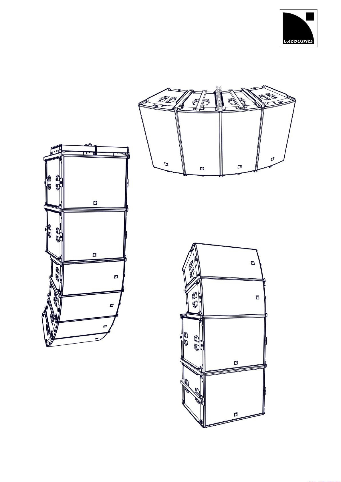
ARCS
ARCS
®
WIDE SYSTEM
®
FOCUS SYSTEM
RIGGING MANUAL
VERSION 3.0
w w w . l - a c o u s t i c s . c o m
Page 2

ARCS® WIDE SYSTEM / ARCS® FOCUS SYSTEM
rigging manual
VERSION 3.0
ARCSWI FO_RM_EN_2. 2 w w w . l - a c o u s t i c s . c o m 2
DANGER
This symbol indicates a potential risk of harm to an individual or damage to the product.
It can also notify the user about instructions that must be strictly followed to ensure safe installation or operation
of the product.
OBLIGATION
This symbol notifies the user about instructions that must be strictly followed to ensure proper installation or
operation of the product.
EQUIPMENT
This symbol indicates the equipment, tools, and spare parts required to perform a procedure.
INFORMATION
This symbol notifies the user about complementary information or optional instructions.
SAFETY INSTRUCTIONS
1. Read this manual
2. Follow all SAFETY INSTRUCTIONS as well as DANGER and OBLIGATION warnings
3. Never incorporate equipment or accessories not approved by L-ACOUSTICS
4. Read all the related PRODUCT INFORMATION documents before exploiting the system
The product information document is included in the shipping carton of the related system component.
5. Work with qualified personnel for rigging the system
Installation should only be carried out by qualified personnel that are familiar with the rigging techniques and safety
recommendations outlined in this manual.
6. Ensure personnel health and safety
During installation and set-up personnel must wear protective headgear and footwear at all times. Under no
circumstances personnel is allowed to climb on a loudspeaker assembly.
7. Respect the Working Load Limit (WLL) of third party equipment
L-ACOUSTICS® is not responsible for any rigging equipment and accessories provided by third party
manufacturers. Verify that the Working Load Limit (WLL) of the suspension points, chain hoists and all additional
hardware rigging accessories is respected.
8. Respect the maximum configurations and the recommended safety level
For safety issue, respect the maximum configurations outlined in this manual. To check the conformity of any
configuration in regards with the safety level recommended by L-ACOUSTICS® , model the system in
SOUNDVISION and refer to the warnings in Mechanical Data section.
®
9. Be cautious when flying a loudspeaker array
Always verify that no one is standing underneath the loudspeaker array when it is being raised. As the array is
being raised, check each individual element to make sure that it is securely fastened to the adjacent element.
Never leave the array unattended during the installation process. As a general rule, L-ACOUSTICS® recommends
the use of safety slings at all times.
10. Be cautious when ground-stacking a loudspeaker array
Do not stack the loudspeaker array on unstable ground or surface. If the array is stacked on a structure, platform,
or stage, always check that the latter can support the total weight of the array. As a general rule, L-ACOUSTICS®
recommends the use of safety straps at all times.
11. Take into account the wind effects on dynamic load
When a loudspeaker assembly is deployed in an open air environment, wind can produce dynamic stress to the
rigging components and suspension points. If the wind force exceeds 6 bft (Beaufort scale), lower down and/or
secure the loudspeaker array.
SYMBOLS
The following symbols are used in this document:
Page 3

ARCSWIFO_RM_EN_3.0 w w w . l - a c o u s t i c s . c o m 3
WELCOME TO L-ACOUSTICS®
Thank you for choosing the L-ACOUSTICS® ARCS® WIDE SYSTEM or ARCS® FOCUS SYSTEM.
This document contains essential information on rigging the system properly. Carefully read this document in order to
become familiar with this procudures.
As part of a continuous evolution of techniques and standards, L-ACOUSTICS® reserves the right to
change the specifications of its products and the content of its documents without prior notice.
Please check the L-ACOUSTICS® web site on a regular basis to download the latest documents: www.l-acoustics.com.
CONTENTS
1 RIGGING SYSTEM COMPONENTS 4
1.1 Loudspeaker enclosures .......................................................................................................................................... 4
1.2 Rigging elements ...................................................................................................................................................... 4
1.3 Software application ................................................................................................................................................ 4
2 MECHANICAL SAFETY 6
2.1 Maximum configurations ......................................................................................................................................... 6
2.2 Assessing mechanical safety ..................................................................................................................................... 7
3 TECHNICAL DESCRIPTION 8
3.1 Flying ........................................................................................................................................................................ 8
3.1.1 WIFOLIFT ................................................................................................................................................ 8
3.1.2 WIFOLIFTBAR ......................................................................................................................................... 9
4 SYSTEM SETUP 10
4.1 Ground-stacking .................................................................................................................................................... 10
Horizontal ............................................................................................................................................................. 10
Horizontal stacked on SB18m .............................................................................................................................. 10
Vertical stacked on SB18m ................................................................................................................................... 10
4.2 Flying ...................................................................................................................................................................... 11
Horizontal 2 or 4 enclosure .................................................................................................................................. 11
Horizontal 3, 5 or 6 enclosure .............................................................................................................................. 12
Vertical ............................................................................................................................................................... 13
4.3 Pole-mounting ....................................................................................................................................................... 14
On feet or on top of SB18m ................................................................................................................................. 14
5 SUBSET PROCEDURES 15
Locking a rigging bar (WIFORIG, SB18MRIG or WIFOLIFT) ......................................................... 15 PROCEDURE A
Using WIFOTILT to adjust ARCS WIDE/FOCUS site angle .......................................................... 16 PROCEDURE B
Attaching a WIFOLIFTBAR ............................................................................................................ 18 PROCEDURE C
5.1.1 Description ............................................................................................................................................ 18
5.1.2 Tilt angle definition and rigging holes choice .......................................................................................... 18
5.1.3 Procedure .............................................................................................................................................. 20
Attaching a shackle or CLAMP250................................................................................................. 22 PROCEDURE D
Mounting the WIFOSOCK ............................................................................................................. 24 PROCEDURE E
APPENDIX A PULLBACK IMPLEMENTATION 25
A. Vertical Array ......................................................................................................................................................... 25
B. Horizontal array ..................................................................................................................................................... 26
APPENDIX B TILT ANGLE REFERENCE CHARTS 27
APPENDIX C RECOMMENDED FLIGHT-CASE 31
APPENDIX D SPECIFICATIONS 32
ARCS® FOCUS ................................................................................................................................................................. 32
ARCS® WIDE.................................................................................................................................................................... 33
SB18m .............................................................................................................................................................................. 34
CLAMP250 ....................................................................................................................................................................... 35
WIFOBUMP ..................................................................................................................................................................... 35
WIFOLIFT ........................................................................................................................................................................ 35
WIFOLIFTBAR ................................................................................................................................................................. 36
WIFOSOCK...................................................................................................................................................................... 36
WIFOTILT ........................................................................................................................................................................ 36
Page 4

ARCS
®
WIDE SYSTEM / ARCS
®
FOCUS SYSTEM
rigging manual
VERSION 3.0
ARCSWIFO_RM_EN_3.0 w w w . l - a c o u s t i c s . c o m 4
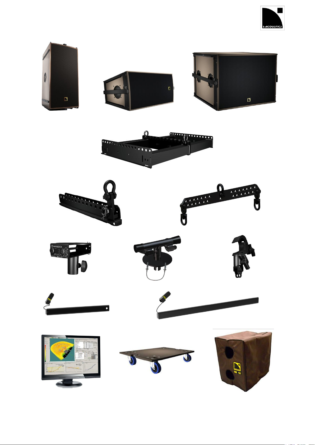
ARCS® WIDE
Full range enclosure, arrayable in a constant curvature line,
provided with 2 WIFORIG coupling bars.
ARCS® FOCUS
Full range enclosure, arrayable in a constant curvature line,
provided with 2 WIFORIG coupling bars.
SB18m
Subwoofer enclosure
provided with 2 SB18MRIG coupling bars.
WIFOBUMP
Frame for flying ARCS® WIDE/FOCUS or SB18m enclosures as a vertical array.
Provided with two bow shackles WLL 1 t.
WIFORIG
Coupling bars dedicated to ARCS® WIDE and ARCS® FOCUS.
Equipped with the LOCKTAB locking tab.
Delivered with the enclosures.
SB18MRIG
Coupling bars dedicated to SB18m.
Equipped with the LOCKTAB locking tab.
Delivered with the enclosure.
WIFOLIFT
Bar for flying two, four, six or eight ARCS® WIDE/FOCUS enclosures as a horizontal array.
Provided with one bow shackle WLL 1 t and one connecting rod.
WIFOLIFTBAR
Bar for flying three, five or six ARCS® WIDE/FOCUS enclosures as a horizontal array.
Provided with one bow shackle WLL 1 t.
WIFOSOCK
Pole mount socket for an ARCS® WIDE/FOCUS enclosure.
CLAMP250
Truss clamp.
WIFOTILT
Rigging accessory for stacking and tilting up to 4 ARCS WIFO on SB18m.
SOUNDVISION
Proprietary 3D acoustical and mechanical modeling software.
Mechanical safety
Before any installation, model the system in SOUNDVISION and check the Mechanical Data section for any
stress warnings.
Other ARCS® WIDE/FOCUS SYSTEM components
All the other components of the system are presented in the ARCS® WIDE/FOCUS SYSTEM user
manual, document in which the loudspeaker configurations and connection are described.
1 RIGGING SYSTEM COMPONENTS
The system approach developed by L-ACOUSTICS® consists in providing packaged solutions for loudspeaker system in
order to guarantee the highest and most predictable level of performance at any step: modeling, installation, and
operation. An L-ACOUSTICS® loudspeaker system is the set of components available to form any loudspeaker system
based on one of the full-range loudspeaker enclosure afforded by L-ACOUSTICS®. It includes enclosures, rigging
accessories, loudspeaker cables, amplified controllers, and software applications.
The main components involved in the rigging process of an ARCS® WIDE SYSTEM or ARCS® FOCUS SYSTEM are
the following:
1.1 Loudspeaker enclosures
1.2 Rigging elements
1.3 Software application
Page 5
ARCSWIFO_RM_EN_3.0 w w w . l - a c o u s t i c s . c o m 5
ARCS® WIDE
ARCS® FOCUS
SB18m
WIFOBUMP
WIFOLIFT
WIFOLIFTBAR
WIFOSOCK
WIFOTILT
CLAMP250
WIFORIG
SB18MRIG
SOUNDVISION
SB18PLA
SB18COV
Components involved in the rigging process of ARCS® WIDE SYSTEM / ARCS® FOCUS SYSTEM
Page 6
ARCS
®
WIDE SYSTEM / ARCS
®
FOCUS SYSTEM
rigging manual
VERSION 3.0
ARCSWIFO_RM_EN_3.0 w w w . l - a c o u s t i c s . c o m 6
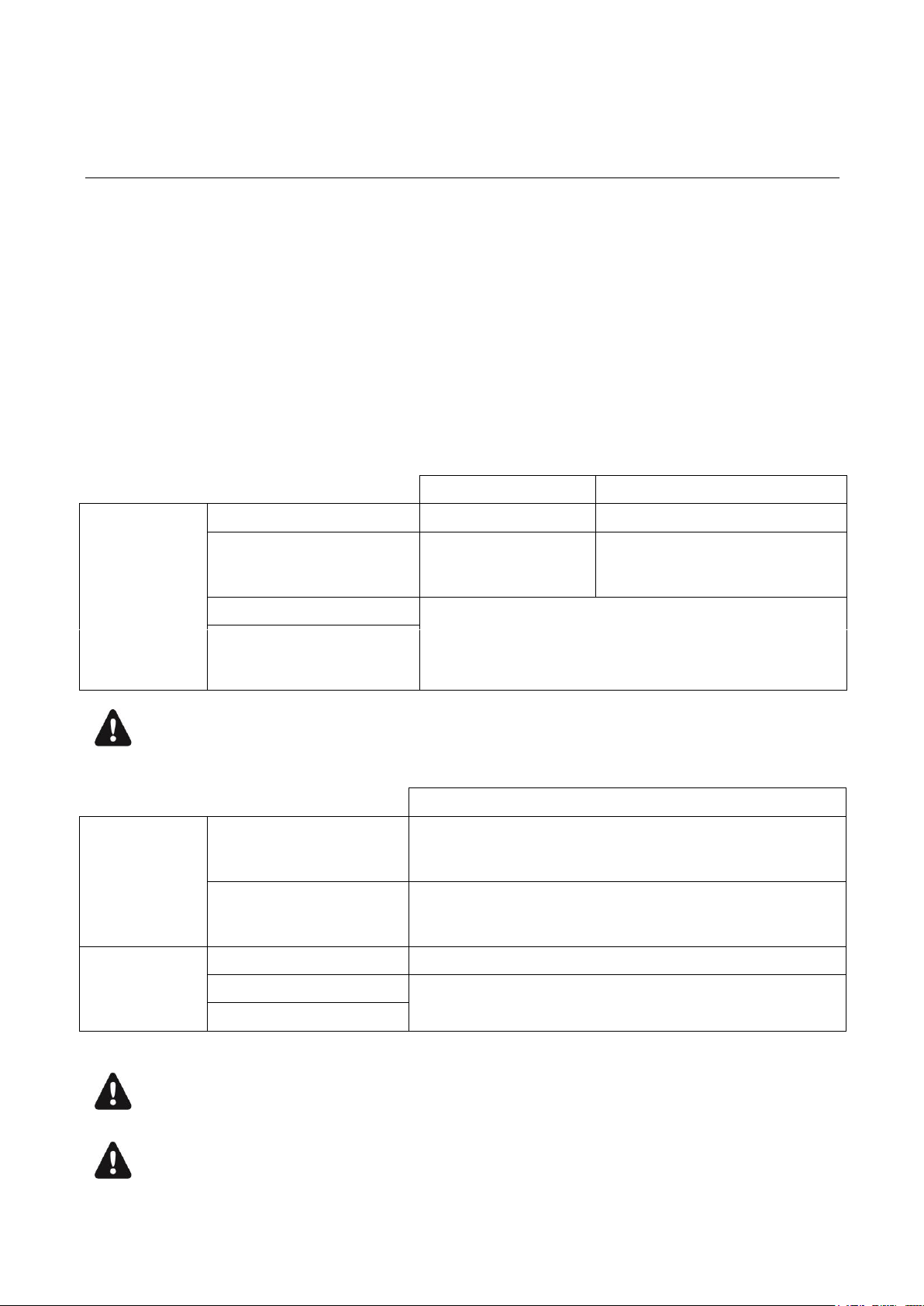
Table 1 Horizontal arrays
Safe
Maximum
Flying
WIFOLIFTBAR
5 ARCS® WIDE/FOCUS
6 ARCS® WIDE or 5 ARCS® FOCUS
WIFOLIFTBAR
+
CLAMP250
5 ARCS® WIDE/FOCUS
6 ARCS® WIDE or 5 ARCS® FOCUS
WIFOLIFT
4 ARCS® WIDE/FOCUS per WIFOLIFT
WIFOLIFT
+
CLAMP250
6 ARCS® WIDE with WIFOLIFTBAR
When flying 6 ARCS® WIDE enclosures with the WIFOLIFTBAR, only use holes no 2,3,4,5,6 of the
WIFOLIFTBAR.
Table 2 Vertical arrays
Safe / Maximum
Flying
WIFOBUMP
8 ARCS® WIDE/FOCUS
or
4 SB18m
WIFOBUMP
+
CLAMP250
6 ARCS® WIDE/FOCUS
or
3 SB18m
Ground-stacking
on ground
2 ARCS® WIDE/FOCUS
on SB18m
4 ARCS® WIDE/FOCUS
WIFOTILT
Maximum 4 ARCS® WIDE/FOCUS under SB18m
In a flown hybrid vertical configuration never attach more than four ARCS® WIDE/FOCUS enclosures under
the SB18m subwoofers.
Mechanical safety of the rigging system
Before any installation, always model the system in SOUNDVISION and check the Mechanical Data
section for any stress warning or stability warning.
2 MECHANICAL SAFETY
2.1 Maximum configurations
The ARCS® WIDE/FOCUS rigging system complies with 2006/42/EC: Machinery Directive. It has been designed
following the guidelines of BGV-C1.
2006/42/EC: Machinery Directive specifies a safety factor of 4:1 against the rupture for flown deployments. The limits
for flown deployments specified in the tables below correspond to a safety factor of 5:1 or higher.
The limits for stacked deployments correspond to safety factor of 1.8:1 or higher.
Refer to SOUNDVISION for the safety factor of a specific deployment.
The safe configurations are always compliant with the standards listed before, regardless of the chosen deployment
parameters (site angles, inter-enclosure angles, etc.).
The maximum configurations correspond to the mechanical limit of the rigging accessories, before deploying these
configurations always model the system in SOUNDVISION and check the Mechanical Data section for any stress
warning or stability warning.
For mixed arrays always refer to your SOUNDVISION model.
Page 7

ARCSWIFO_RM_EN_3.0 w w w . l - a c o u s t i c s . c o m 7
Rated working load limit (WLL) is not enough
The rated WLL is an indication of the element resistance to tensile stress. For complex mechanical systems
such as loudspeaker arrays, WLLs cannot be used per se to determine the maximum number of enclosures
within an array or to assess the safety of a specific array configuration.
Mechanical modeling with SOUNDVISION
The working load applied to each linking point, along with the corresponding safety factor, will depend on
numerous variables linked to the composition of the array (type and number of enclosures, splay angles) and
the implementation of the flying or stacking structure (number and location of flying points, site angle). This
cannot be determined without the complex mechanical modeling and calculation offered by SOUNDVISON.
Assessing the safety with SOUNDVISION
The overall safety factor of a specific mechanical configuration always corresponds to the lowest safety factor
among all the linking points. Always model the system configuration with the SOUNDVISION software and
check the Mechanical Data section to identify the weakest link and its corresponding working load. By
default, a stress warning will appear when the mechanical safety goes beyond the recommended safety level.
Safety of ground-stacked arrays in SOUNDVISION
For ground-stacked arrays, a distinct stability warning is implemented in SOUNDVISION. It indicates a tipping
hazard when the array is not secured to the ground, stage or platform. It is user responsibility to achieve full
anchorage and to ignore this warning.
Consideration must be given to unusual conditions
SOUNDVISION calculations are based upon usual environmental conditions. A higher safety factor is
recommended with factors such as extreme high or low temperatures, strong wind, prolonged exposition to
salt water, etc. Always consult a rigging specialist to adopt safety practices adapted to such a situation.
2.2 Assessing mechanical safety
In order to assess the actual safety of any array configuration before implementation, refer to the following warnings:
Page 8
ARCS
®
WIDE SYSTEM / ARCS
®
FOCUS SYSTEM
rigging manual
VERSION 3.0
ARCSWIFO_RM_EN_3.0 w w w . l - a c o u s t i c s . c o m 8
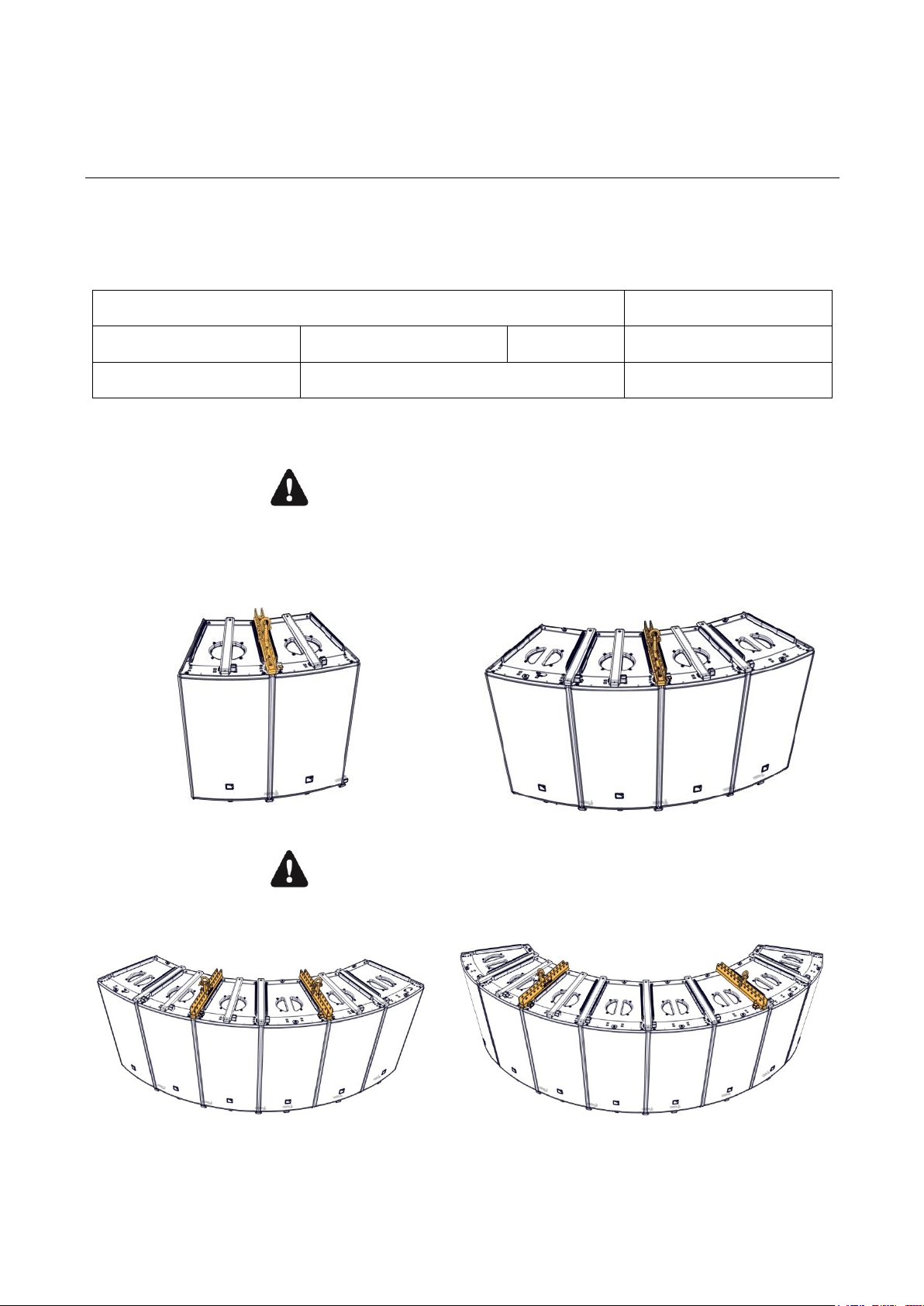
1 load-bearing line
2 load-bearing lines
2 or 4 ARCS WIDE / FOCUS
3 or 5 ARCS WIDE / FOCUS
6 ARCS WIDE
6 or 8 ARCS WIDE / FOCUS
1 WIFOLIFT
2 WIFOLIFT + 1 WIFOLIFTBAR
2 WIFOLIFT
Maximum of four enclosures per WIFOLIFT.
Always use 1 load-bearing line per pick-up point.
Only lift symmetrical arrays.
Each side of the array must mirror the other.
1 WIFOLIFT
No bridled suspension on two WIFOLIFT bars.
Always use 1 load-bearing line per pick-up point.
2 WIFOLIFT
3 TECHNICAL DESCRIPTION
3.1 Flying
The ARCS WIDE/FOCUS system can using WIFOLIFT or WIFOLIFTBAR depending on two factors:
- number of load-bearing lines,
- number of enclosures.
Follow the indications in this table to know which accessories to use:
3.1.1 WIFOLIFT
Page 9
ARCSWIFO_RM_EN_3.0 w w w . l - a c o u s t i c s . c o m 9
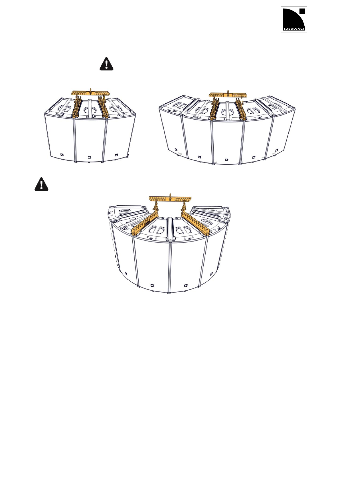
Only lift symmetrical arrays.
Each side of the array must mirror the other.
2 WIFOLIFT and 1 WIFOLIFTBAR
ARCS® WIDE only
When used with 6 enclosures, the WIFOLIFTBAR is only compatible with ARCS® WIDE.
3.1.2 WIFOLIFTBAR
Page 10
ARCS
®
WIDE SYSTEM / ARCS
®
FOCUS SYSTEM
rigging manual
VERSION 3.0
ARCSWIFO_RM_EN_3.0 w w w . l - a c o u s t i c s . c o m 10
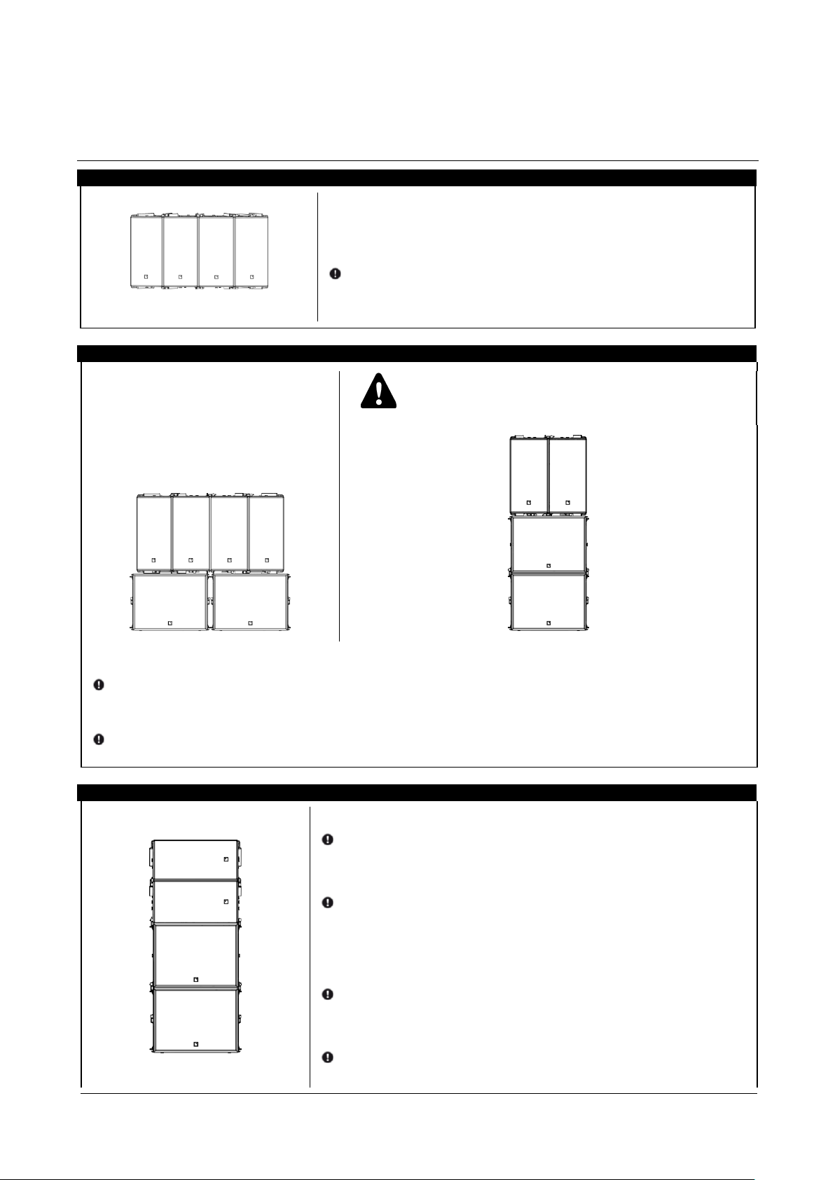
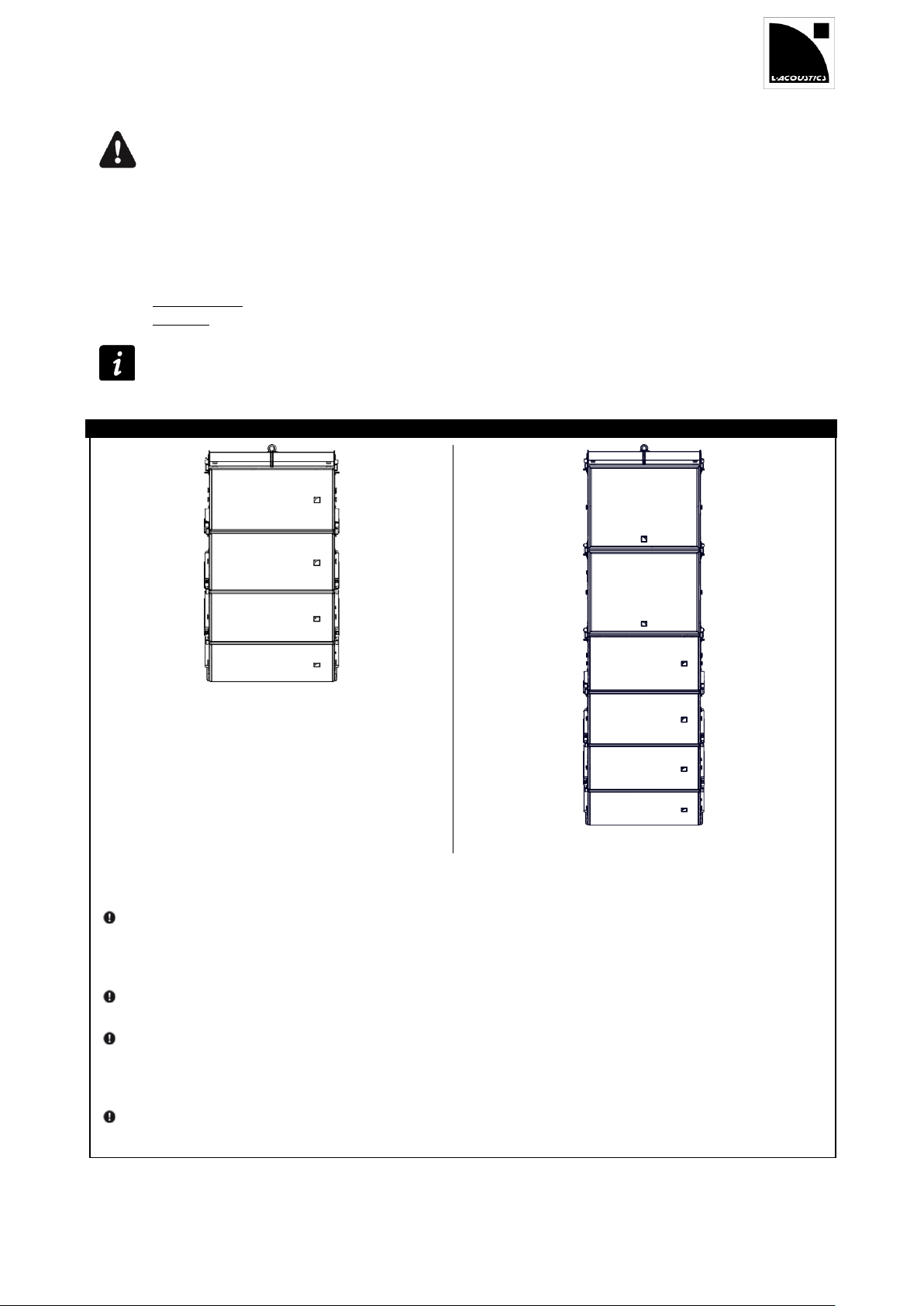
Place the enclosures side-by-side, logo down, with their rails aligned.
Slide and lock the bars into all top adjacent rails.
Refer to PROCEDURE A.
Use safety straps at all times.
Anchor the array since the ARCS WIDE / FOCUS
enclosures are not secured to the SB18m.
Stack SB18m horizontally or vertically, logo down.
If SB18m enclosures are vertically stacked, attach them: refer to PROCEDURE A.
Place the ARCS
®
WIDE/FOCUS enclosures on top of the subwoofers, side-by-side with rails aligned.
Slide and lock the WIFORIG bars on the top adjacent ARCS
®
WIDE/FOCUS rails.
Refer to PROCEDURE A.
Stack and attach as many SB18m enclosures as necessary (logo down).
Refer to PROCEDURE A.
To adjust the ARCS WIDE/FOCUS site angle, use a WIFOTILT.
Refer to PROCEDURE B.
Otherwise, place the ARCS WIDE/FOCUS enclosures with rails aligned
on top of the subwoofer(s).
Attach ARCS WIDE/FOCUS to SB18m.
Refer to PROCEDURE A.
Attach up to three more ARCS WIDE/FOCUS on top.
Refer to PROCEDURE A.
4 SYSTEM SETUP
4.1 Ground-stacking
Horizontal
Horizontal stacked on SB18m
Vertical stacked on SB18m
Page 11
ARCSWIFO_RM_EN_3.0 w w w . l - a c o u s t i c s . c o m 11
4.2 Flying
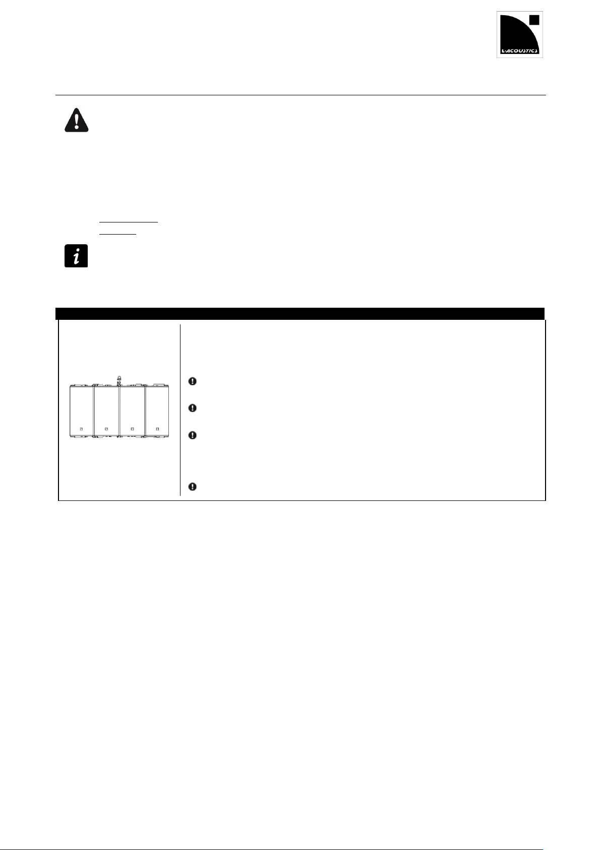
No bridled suspension on two WIFOLIFT bars.
Always use 1 load-bearing line per pick-up point.
Pullback implementation
By using rigging points at the rear of the installed coupling bars, an ARCS® WIDE/FOCUS horizontal or
vertical array can be implemented in pullback configuration. Refer to APPENDIX A PULLBACK
IMPLEMENTATION.
Final check before flying the system
Coupling bars: All lugs of locking tabs must be secured, as indicated in PROCEDURE A.
Shackles: All safety pins must be secured as indicated in PROCEDURE D.
Truss clamping
By installing a CLAMP250 instead of a shackle, an array can be attached to a truss.
Refer to PROCEDURE D Attaching a shackle or CLAMP250.
Place the enclosures in vertical position, side-by-side, logo down and rails aligned.
Remove all top WIFORIG bars from their storage location.
Install the WIFOLIFT bar(s).
See WIFOLIFT p 8-9.
Refer to PROCEDURE A.
Slide and lock the WIFORIG bars into all top remaining adjacent rails.
Refer to PROCEDURE A.
Attach a shackle on each of the WIFOLIFT bars.
Refer to PROCEDURE D.
Slightly raise the array.
Remove all bottom WIFORIG bars from their storage location.
Slide and lock WIFORIG bars into all bottom adjacent rails.
Refer to PROCEDURE A.
Horizontal 2 or 4 enclosure
Page 12
ARCS
®
WIDE SYSTEM / ARCS
®
FOCUS SYSTEM
rigging manual
VERSION 3.0
ARCSWIFO_RM_EN_3.0 w w w . l - a c o u s t i c s . c o m 12
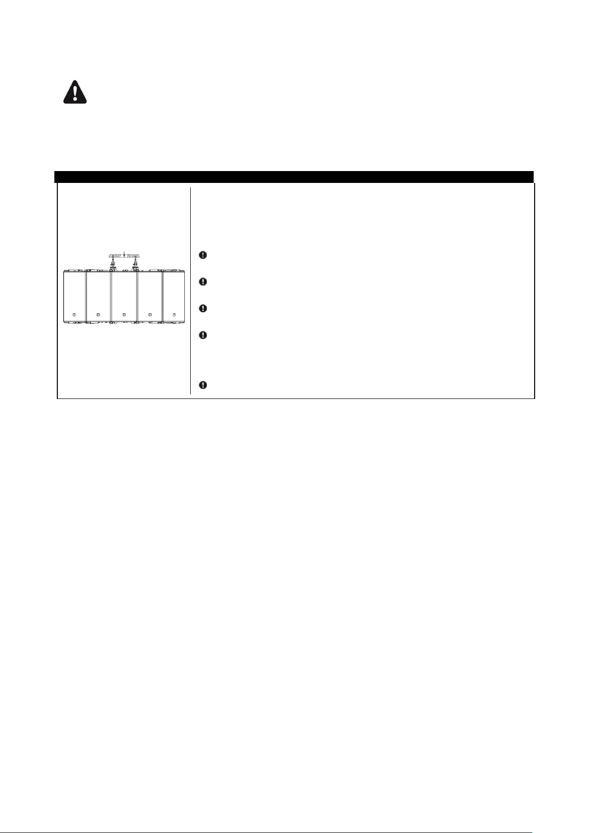
WIFOLIFTBAR positioning
Refer to WIFOLIFT on page 8-9.
Hybrid arrays
If you are implementing a hybrid configuration carefully follow the verification procedure outlined in
PROCEDURE C Attaching a WIFOLIFTBAR
Place the enclosures in vertical position, side-by-side, logo down and rails
aligned.
Remove all top WIFORIG bars from their storage location.
Install the WIFOLIFT bar(s).
See WIFOLIFT p 8-9 at the beginning of this section.
Refer to PROCEDURE A.
Slide and lock the WIFORIG bars into all top remaining adjacent rails.
Refer to PROCEDURE A.
Attach a WIFOLIFTBAR to the two WIFOLIFT.
Refer to PROCEDURE C.
Attach a shackle or a CLAMP250 to the WIFOLIFTBAR.
Refer to PROCEDURE D.
Slightly raise the array.
Remove all bottom WIFORIG bars from their storage location.
Slide and lock WIFORIG bars into all bottom adjacent rails.
Refer to PROCEDURE A.
Horizontal 3, 5 or 6 enclosure
Page 13
ARCSWIFO_RM_EN_3.0 w w w . l - a c o u s t i c s . c o m 13
No bridled suspension on the WIFOBUMP frame
Always use 1 load-bearing line per pick-up point.
Pullback implementation
By using rigging points at the rear of the installed coupling bars, an ARCS® WIDE/FOCUS horizontal or
vertical array can be implemented in pullback configuration. Refer to APPENDIX A PULLBACK
IMPLEMENTATION.
Final check before flying the system
Coupling bars: All lugs of locking tabs must be secured, as indicated in PROCEDURE A.
Shackles: All safety pins must be secured as indicated in PROCEDURE D.
Truss clamping
By installing a CLAMP250 instead of a shackle, an array can be attached to a truss.
Refer to PROCEDURE D.
Place the first enclosure (WIDE, FOCUS or SB18m) on the floor.
For an array with 2 SB18m, place and lock a second SB18m on top of the first one.
Refer to PROCEDURE A to lock the SB18MRIG bars.
Remove the top coupling bars from their storage location.
Place the WIFOBUMP frame on the top enclosure and lock the coupling bars.
With an SB18m on top, refer to SOUNDVISION for the frame position (front or rear).
Refer to PROCEDURE A to lock the coupling bars.
Attach a shackle on the WIFOBUMP.
Refer to PROCEDURE D.
Raise the array so you are comfortable lifting and attaching the next enclosure.
Bring the next enclosure and remove the bars from their storage location.
With the rigging bar in hand, lift the next enclosure and attach it under the array.
Refer to PROCEDURE A to lock the coupling bars.
To add more enclosures, repeat the previous 3 steps until the array is completed.
Vertical
Page 14
ARCS
®
WIDE SYSTEM / ARCS
®
FOCUS SYSTEM
rigging manual
VERSION 3.0
ARCSWIFO_RM_EN_3.0 w w w . l - a c o u s t i c s . c o m 14
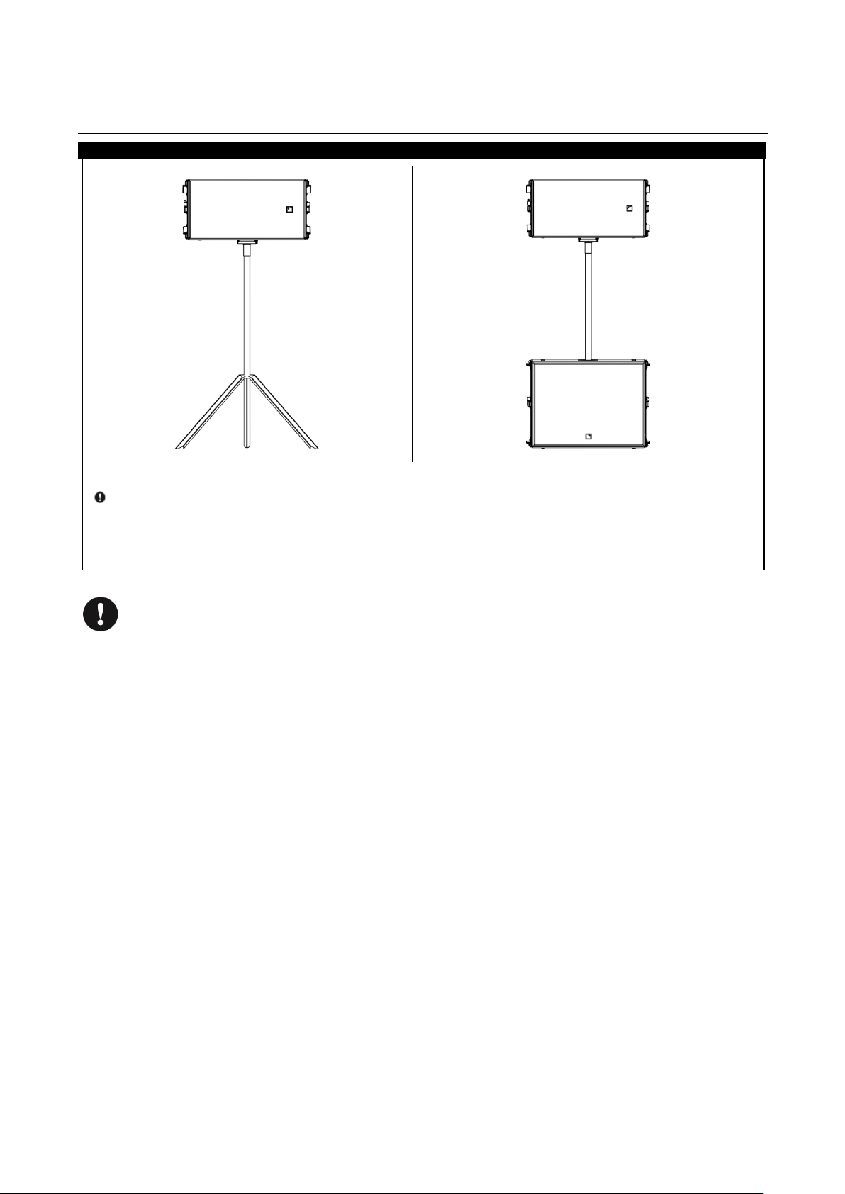
Install a WIFOSOCK on an ARCS
®
WIDE/FOCUS enclosure.
Refer to PROCEDURE E.
Insert the pole into the WIFOSOCK socket.
If needed, insert the other extremity of the pole into an SB18m socket.
Tip the assembly to a vertical position.
Dismantling the system
Identify the array to dismount and apply the associated System setup procedure in reversed order.
4.3 Pole-mounting
On feet or on top of SB18m
Page 15
ARCSWIFO_RM_EN_3.0 w w w . l - a c o u s t i c s . c o m 15
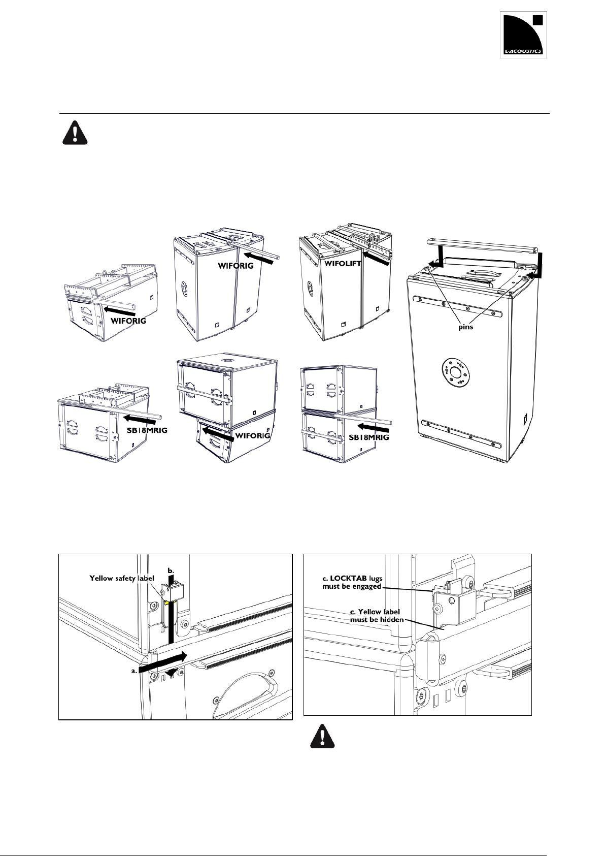
Coupling bars and SB18m
Only use the longer SB18MRIG bars stored on the SB18m subwoofers to attach SB18m to another SB18m
or to a WIFOBUMP.
The shorter WIFORIG bars do not ensure the mechanical safety of these connections.
1. Remove the bar from its storage location.
2. From the front of the array, slide the bar into adjacent rigging rails.
Storage position
3. Secure the bar with the locking tab.
Accurately position the bar by pushing it into place.
Pinch the spring tongue and slide the locking tab until it snaps
into place.
When encountering difficulty, try to slide the tab from the
other side.
Always check that the yellow label is fully covered
to ensure the locking tabs are fully engaged.
5 SUBSET PROCEDURES
Locking a rigging bar (WIFORIG, SB18MRIG or WIFOLIFT) PROCEDURE A
Page 16
ARCS
®
WIDE SYSTEM / ARCS
®
FOCUS SYSTEM
rigging manual
VERSION 3.0
ARCSWIFO_RM_EN_3.0 w w w . l - a c o u s t i c s . c o m 16
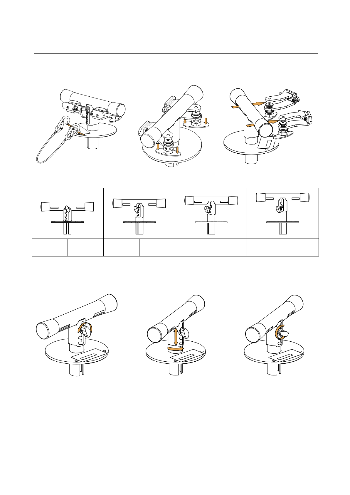
Remove the locking tabs and sling from WIFOTILT.
Adjust WIFOTILT angle.
WIDE
FOCUS
WIDE
FOCUS
WIDE
FOCUS
WIDE
FOCUS
0°
-7.5°
-2.5°
-10°
-5°
-12.5°
-7.5°
-15°
Loosen the knob.
Select the angle and notch the corresponding
slit on the knob screw.
Turn the T-shape support and
tighten the knob.
PROCEDURE B
Using WIFOTILT to adjust ARCS WIDE/FOCUS site angle
Page 17
ARCSWIFO_RM_EN_3.0 w w w . l - a c o u s t i c s . c o m 17
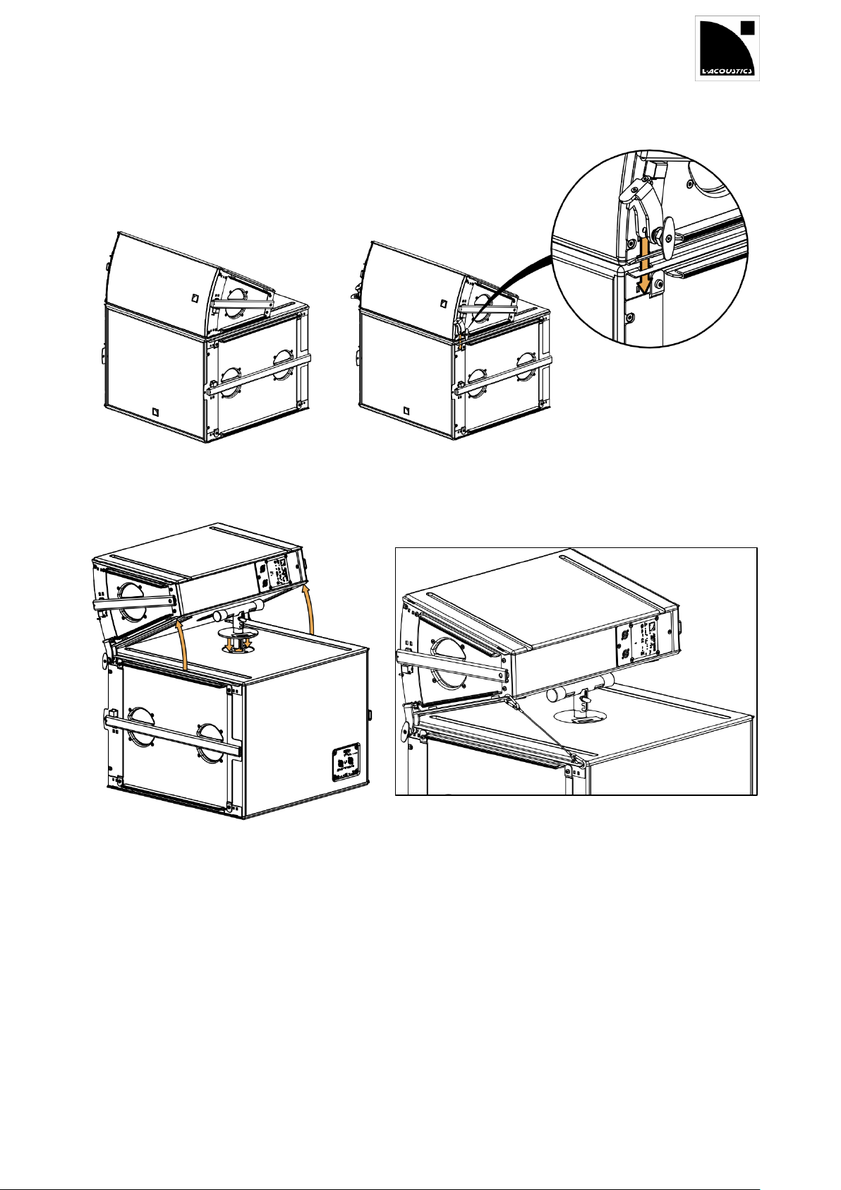
Position the first ARCS WIDE / FOCUS on
the SB18m with rails aligned.
Slide the WIFOTILT tabs through the holes at the front of both
enclosures rails.
Lift the back of ARCS WIDE / FOCUS and place
the WIFOTILT in the SB18m pole socket.
Attach the sling to the back holes of each enclosure rail on one
side of the assembly.
Page 18
ARCS
®
WIDE SYSTEM / ARCS
®
FOCUS SYSTEM
rigging manual
VERSION 3.0
ARCSWIFO_RM_EN_3.0 w w w . l - a c o u s t i c s . c o m 18
PROCEDURE C
5.1.1 Description
The WIFOLIFTBAR is a rigging accessory used to fly 3 or 5 ARCS® WIDE/FOCUS or 6 ARCS® WIDE.
It is used with two WIFOLIFT that are positioned on the array depending on the number of enclosures, WIFOLIFT p
8-9.
The WIFOLIFTBAR is composed of a metal bar with two rows of 15 holes and 2 swivel shackles. It can be used with a
bow shackle WLL 1 t or a CLAMP250 attached to one of the two central holes. The swivel shackles can be attached the
other 28 holes to connect the WIFOLIFTBAR to the two WIFOLIFT.
5.1.2 Tilt angle definition and rigging holes choice
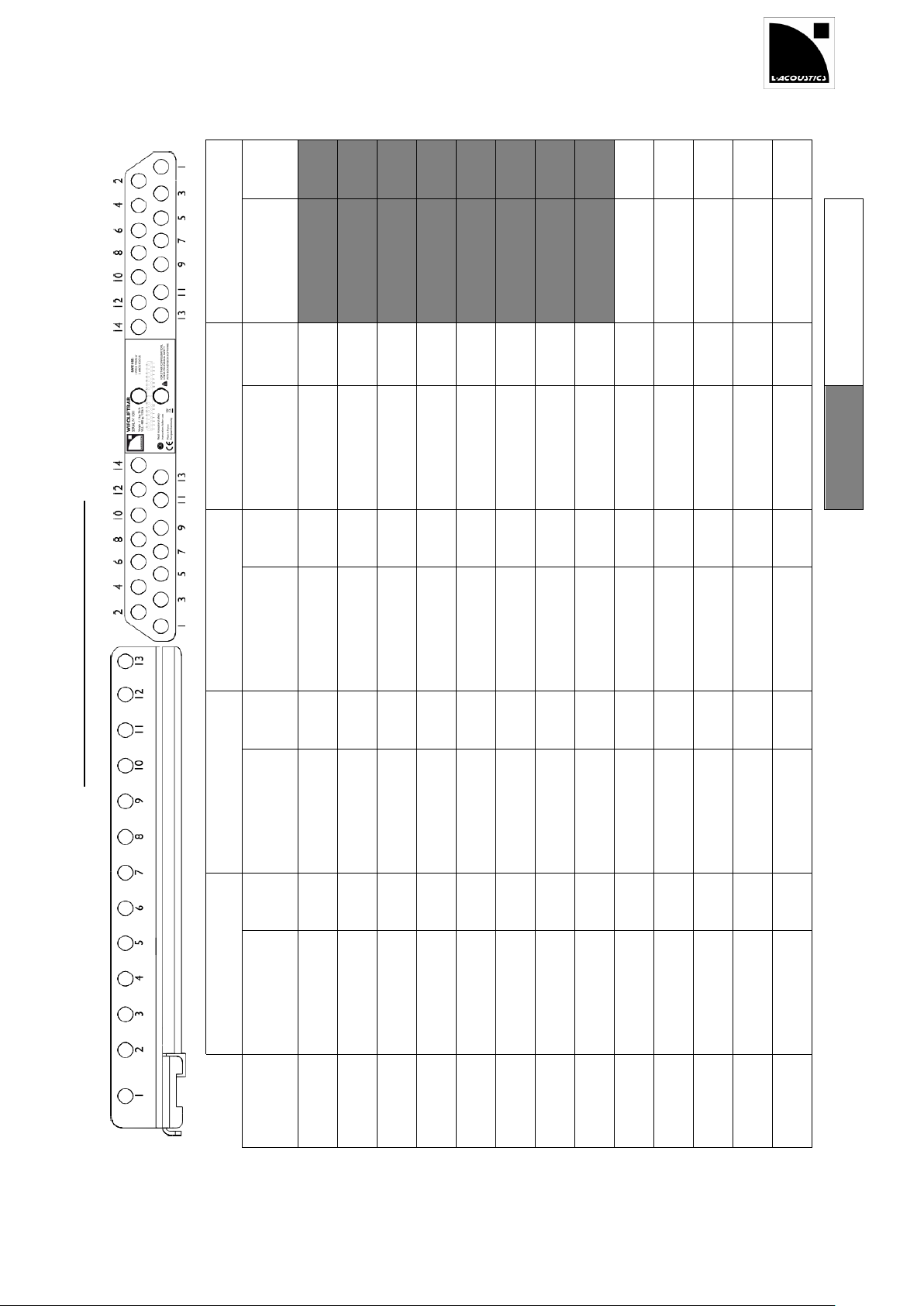
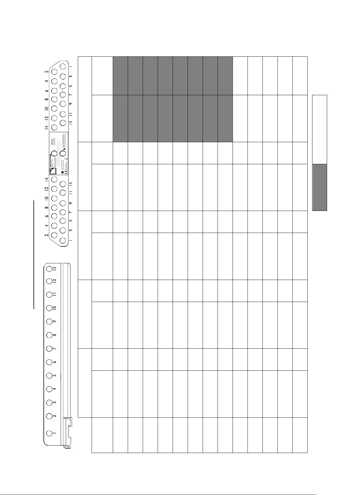
The tilt angle of an array is defined by the holes selected on the WIFOLIFT.
For homogeneous arrays (ARCS® WIDE or FOCUS), refer to the Tilt angle reference chart on the next page to
define which WIFOLIFT holes correspond to your target tilt angle and which WIFOLIFTBAR holes to use.
For example, rigging a three ARCS® FOCUS array on holes no 1 on the WIFOLIFT yield a 26.5° positive angle and
requires attaching the swivel shackles to holes no 2 on the WIFOLIFTBAR.
For hybrid arrays (ARCS® WIDE and FOCUS), a trial-and-error process must be applied to define the appropriate
WIFOLIFT and WIFOLIFTBAR holes.
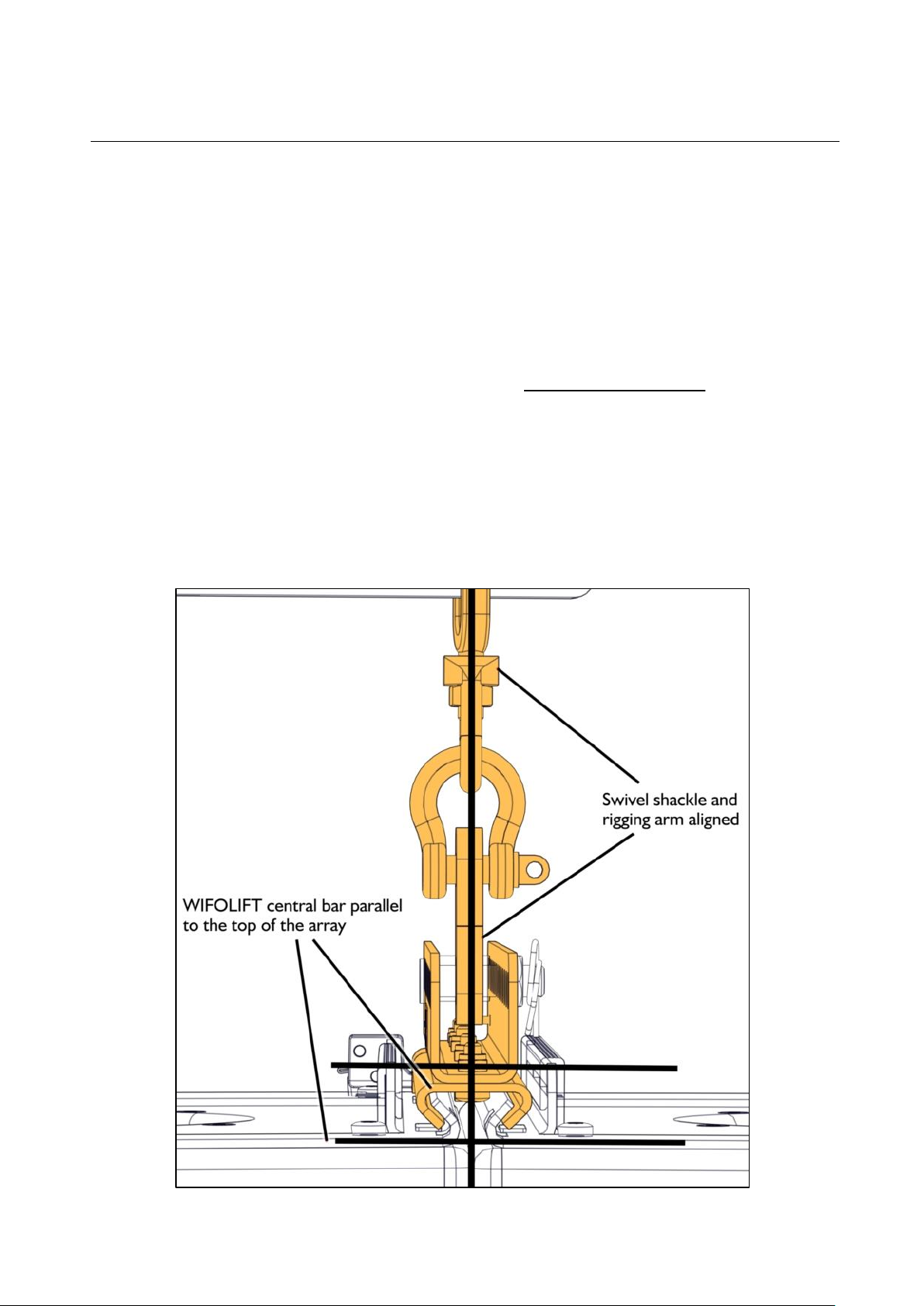
The goal is to reduce the stress on the WIFOLIFT to a minimum:
- the rigging arm and the swivel shackle must be aligned
- the WIFOLIFT bar must remain parallel to the top of the array.
Attaching a WIFOLIFTBAR
Page 19
ARCSWIFO_RM_EN_3.0 w w w . l - a c o u s t i c s . c o m 19
Tilt angle reference chart WIFOLIFTBAR
6 ARCS
®
WIDE
Tilt
angle
5,1°
1,4°
-2,2°
-5,7°
-9,3°
WIFOLIFTBAR
HOLE
2 3 4 5 6
= not applicable
5 ARCS
®
WIDE
Tilt
angle
34,7°
30,9°
27,5°
23,9°
20,2°
16,3°
12,4°
8,2°
4,0°
-0,1°
-4,3°
-8,8°
-12,5°
WIFOLIFTBAR
HOLE
1 2 3 4 5 6 7
9
10
11
12
13
14
5 ARCS
®
FOCUS
Tilt
angle
32,3°
28,0°
24,4°
20,4°
16,4°
12,1°
7,8°
3,3°
-1,3°
-5,7°
-10,0°
-14,4°
-18,2°
WIFOLIFTBAR
HOLE
2 3 3 4 4 5 5 6 6 7 7 8 8
3 ARCS
®
WIDE
Tilt
angle
26,0°
21,8°
17,9°
13,8°
9,5°
4,4°
1,1°
-3,2°
-7,4°
-11,7°
-15,7°
-19,7°
-23,1°
WIFOLIFTBAR
HOLE
2 3 4 5 6 7 8
9
10
11
12
13
14
3 ARCS
®
FOCUS
Tilt
angle
26,5°
21,6°
17,6°
13,4°
9,0°
4,8°
0,2°
-4,4°
-8,9°
-13,1°
-17,3°
-21,4°
-25,0°
WIFOLIFTBAR
HOLE
2 3 3 4 5 5 6 6 7 7 8 8 9
WIFOLIFT
hole
1 2 3 4 5 6 7 8 9
10
11
12
13
Page 20

ARCS
®
WIDE SYSTEM / ARCS
®
FOCUS SYSTEM
rigging manual
VERSION 3.0
ARCSWIFO_RM_EN_3.0 w w w . l - a c o u s t i c s . c o m 20
Risk of fall.
The WIFOLIFT must be parallel to the top of the array. Any other situation creates mechanical stress and can
cause the WIFOLIFT to pop out.
5.1.3 Procedure
If you are raising a hybrid array (ARCS® WIDE and FOCUS), follow these steps:
1. Select the WIFOLIFT and WIFOLIFTBAR holes to define a starting point.
The values given in the Tilt angle reference chart can be used as a guideline.
Select the array which composition is the closest to your hybrid array and use the indicated WIFOLIFT and
WIFOLIFTBAR.
For example, to reach a 0,2° tilt angle with an array of 2 ARCS® WIDE and 1 ARCS® FOCUS, refer to the 3 ARCS®
WIDE array and use WIFOLIFT hole no 7 and WIFOLIFTBAR hole no 8.
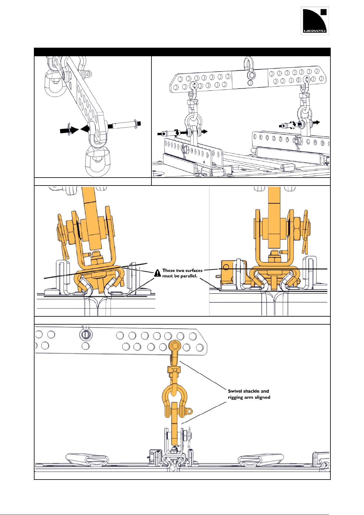
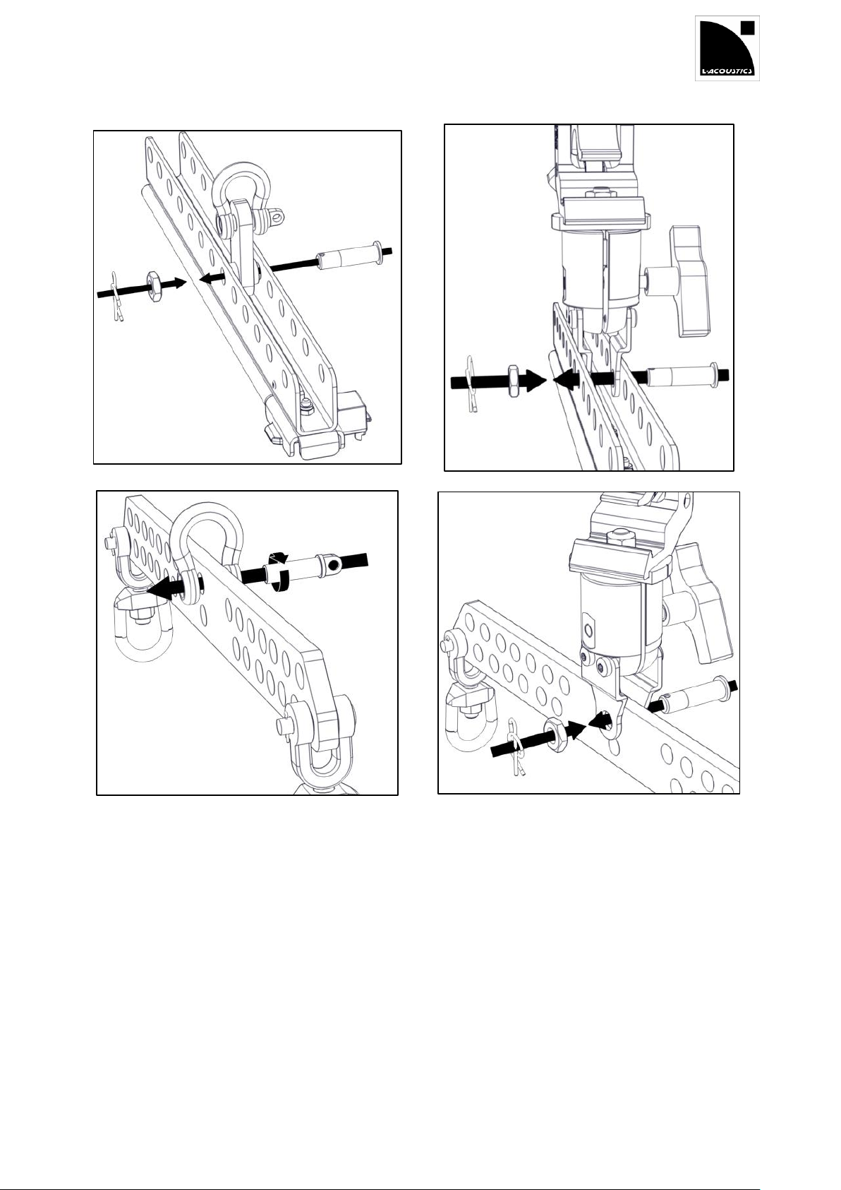
2. Attach two swivel shackles to the indicated holes on a WIFOLIFTBAR.
3. Attach the WIFOLIFTBAR to the indicated hole on the two WIFOLIFT.
a. Attach a rigging arm to the selected hole on each WIFOLIFT by driving and securing the pierced bolt.
b. Pass the U-shaped part of the shackle through the swivel shackle loop.
c. Attach the bow shackle to the arm.
d. Secure the shackle.
4. Raise the array so you can measure the angle.
If you are not satisfied, lower the array to the ground and adjust the angle by picking another hole.
If you are satisfied with the angle, continue.
5. Verify that the central bar of the two WIFOLIFT is parallel to the top of the array.
If it is parallel, the array is ready.
If it is not parallel, follow these steps:
a. Lower the array to the ground.
b. Change the swivel shackles rigging holes on the WIFOLIFTBAR so that the rigging arm and the swivel shackle
form a straight line.
c. Repeat step 5 until the central bar of the WIFOLIFT is parallel to the top of the array.
If you are raising an homogeneous array,
1. Select the appropriate WIFOLIFT and WIFOLIFTBAR holes using the Tilt angle reference chart on the previous
page
2. Attach two swivel shackles to the indicated holes on a WIFOLIFTBAR.
3. Attach the WIFOLIFTBAR to the indicated hole on the two WIFOLIFT.
a. Attach a rigging arm to the WIFOLIFT hole by driving and securing the pierced bolt.
b. Pass the U-shaped part of the shackle through the swivel shackle loop.
c. Attach the bow shackle to the arm.
d. Secure the shackle.
Page 21
ARCSWIFO_RM_EN_3.0 w w w . l - a c o u s t i c s . c o m 21
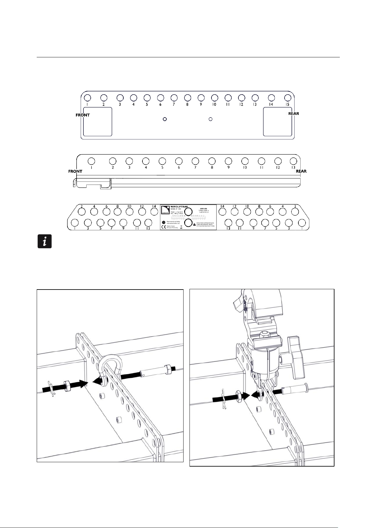
PROCEDURE D: Attaching a WIFOLIFTBAR
Securing a swivel shackle on WIFOLIFTBAR.
Securing the WIFOLIFTBAR to the two WIFOLIFT.
Verifying the WIFOLIFT central bar is parallel to the top of the array.
Verifying the alignment of the swivel shackle and the rigging arm.
Page 22
ARCS
®
WIDE SYSTEM / ARCS
®
FOCUS SYSTEM
rigging manual
VERSION 3.0
ARCSWIFO_RM_EN_3.0 w w w . l - a c o u s t i c s . c o m 22
About site angle
Since many variables can affect the actual site angle, it is recommended to use an inclinometer.
Attach and secure a shackle or a CLAMP250 to the identified hole, by driving the pierced bolt.
With a CLAMP250, install safety slings between the KIBU-SB and the truss.
PROCEDURE D
1. Refer to SOUNDVISION modeling or to the table in APPENDIX B TILT ANGLE REFERENCE CHART to
identify the hole that corresponds to the targeted tilt angle.
Attaching a shackle or CLAMP250
WIFOBUMB HOLES
WIFOLIFT HOLES
WIFOLIFTBAR HOLES
Page 23
ARCSWIFO_RM_EN_3.0 w w w . l - a c o u s t i c s . c o m 23
Page 24
ARCS
®
WIDE SYSTEM / ARCS
®
FOCUS SYSTEM
rigging manual
VERSION 3.0
ARCSWIFO_RM_EN_3.0 w w w . l - a c o u s t i c s . c o m 24
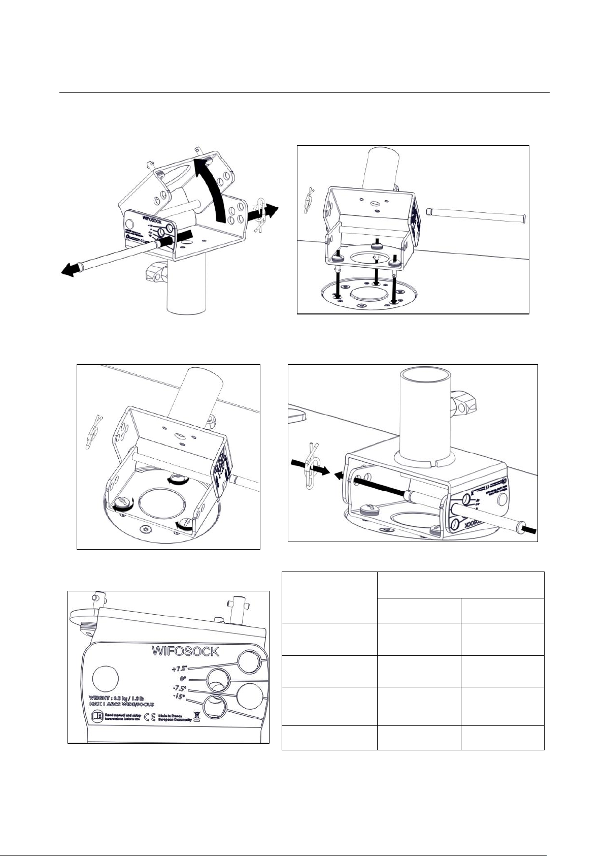
Remove the pin from the angle hole.
Place the WIFOSOCK onto the socket receptacle of the
enclosure.
Secure the WIFOSOCK by applying a quarter-turn
rotation to the three screws, with a coin or a
screwdriver.
Insert the pin into the appropriate angle hole.
Possible angles on the WIFOSOCK
Selected angle on
WIFOSOCK
Realized site angle
ARCS® WIDE
ARCS® FOCUS
-15,0°
0,0°
-7,5°
-7,5°
7,5°
0,0°
0,0°
15,0°
7,5°
7,5°
22,5°
15,0°
PROCEDURE E
Mounting the WIFOSOCK
Page 25

ARCSWIFO_RM_EN_3.0 w w w . l - a c o u s t i c s . c o m 25
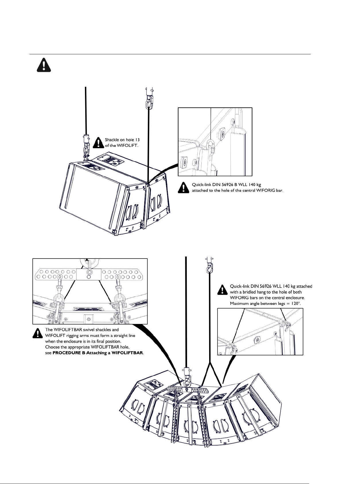
Maximum configurations.
2 or 4 ARCS® WIDE/FOCUS enclosures array for 1 WIFOBUMP frame.
6 or 8 ARCS® WIDE/FOCUS enclosures array for 2 WIFOBUMP frames.
APPENDIX A PULLBACK IMPLEMENTATION
A. Vertical Array
Page 26
ARCS
®
WIDE SYSTEM / ARCS
®
FOCUS SYSTEM
rigging manual
VERSION 3.0
ARCSWIFO_RM_EN_3.0 w w w . l - a c o u s t i c s . c o m 26
Maximum configurations.
2 or 4 ARCS® WIDE/FOCUS enclosures array for 1 WIFOLIFT.
3 or 5 ARCS® WIDE/FOCUS enclosures array for 2 WIFOLIFT and 1 WIFOLIFTBAR.
B. Horizontal array
Page 27
ARCSWIFO_RM_EN_3.0 w w w . l - a c o u s t i c s . c o m 27
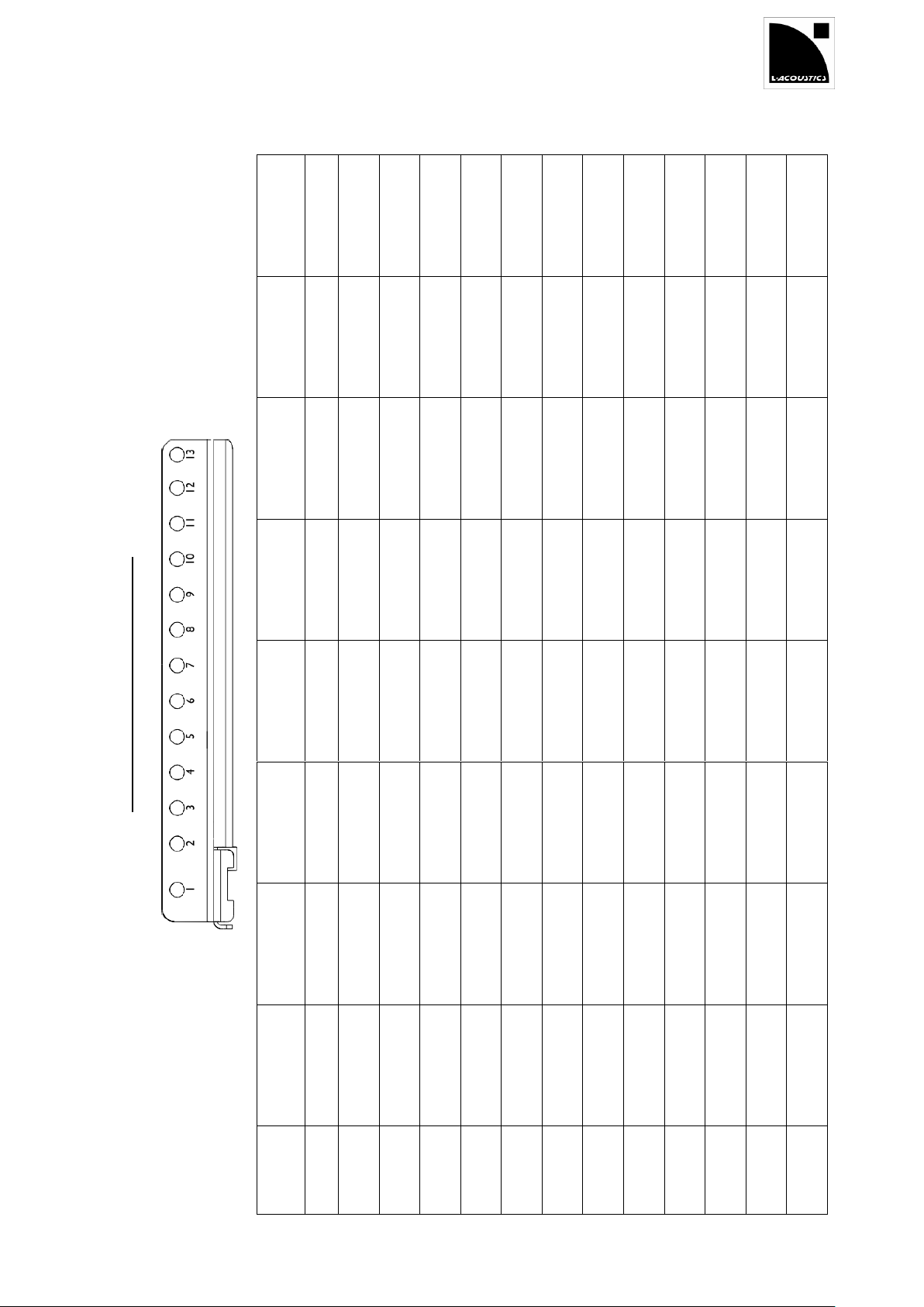
Tilt angle reference chart WIFOLIFT
8 ARCS
®
WIDE
18,1°
15,4°
13,2°
11,0°
8,8°
6,5°
4,2°
1,9°
-0,4°
-2,7°
-5,0°
-7,3°
-9,3°
8 ARCS
®
FOCUS
27,0°
22,8°
19,3°
15,7°
12,0°
8,2°
4,2°
0,3°
-3,7°
-7,6°
-11,4°
-15,2°
-18,5°
6 ARCS
®
WIDE
33,1
29,5
26,5
23,4
20,0
16,6
13,0
9,3
5,5
1,7
-2,2
-6,0
-9,5
6 ARCS
®
FOCUS
37,3
33,7
30,6
27,3
23,8
20,1
16,2
12,2
8,1
3,8
-0,5
-4,8
-8,7
4 ARCS
®
WIDE
33,4°
29,1°
25,5°
21,6°
17,6°
13,3°
8,9°
4,4°
-0,2°
-4,7°
-9,3°
-13,7°
-17,6°
4 ARCS
®
FOCUS
30,7°
26,1°
22,3°
18,2°
14,0°
9,6°
5,1°
0,5°
-4,1°
-8,6°
-13,1°
-17,4°
-21,2°
2 ARCS
®
WIDE
26,6°
21,6°
17,5°
13,1°
8,7°
4,1°
-0,5°
-5,2°
-9,7°
-14,2°
-18,4°
-22,5°
-26,1°
2 ARCS
®
FOCUS
26,4°
21,3°
17,2°
12,9°
8,4°
3,8°
-0,9°
-5,5°
-10,1°
-14,5°
-18,8°
-22,9°
-26,4°
WIFOLIFT
hole
1 2 3 4 5 6 7 8 9
10
11
12
13
APPENDIX B TILT ANGLE REFERENCE CHARTS
Page 28
ARCS
®
WIDE SYSTEM / ARCS
®
FOCUS SYSTEM
rigging manual
VERSION 3.0
ARCSWIFO_RM_EN_3.0 w w w . l - a c o u s t i c s . c o m 28
Tilt angle reference chart WIFOLIFTBAR
6 ARCS
®
WIDE
Tilt angle
5,1°
1,4°
-2,2°
-5,7°
-9,3°
WIFOLIFTBAR
HOLE
2 3 4 5 6
= not applicable
5 ARCS
®
WIDE
Tilt
angle
34,7°
30,9°
27,5°
23,9°
20,2°
16,3°
12,4°
8,2°
4,0°
-0,1°
-4,3°
-8,8°
-12,5°
WIFOLIFTBAR
HOLE
1 2 3 4 5 6 7
9
10
11
12
13
14
5 ARCS
®
FOCUS
Tilt
angle
32,3°
28,0°
24,4°
20,4°
16,4°
12,1°
7,8°
3,3°
-1,3°
-5,7°
-10,0°
-14,4°
-18,2°
WIFOLIFTBAR
HOLE
2 3 3 4 4 5 5 6 6 7 7 8 8
3 ARCS
®
WIDE
Tilt
angle
26,0°
21,8°
17,9°
13,8°
9,5°
4,4°
1,1°
-3,2°
-7,4°
-11,7°
-15,7°
-19,7°
-23,1°
WIFOLIFTBAR
HOLE
2 3 4 5 6 7 8
9
10
11
12
13
14
3 ARCS
®
FOCUS
Tilt
angle
26,5°
21,6°
17,6°
13,4°
9,0°
4,8°
0,2°
-4,4°
-8,9°
-13,1°
-17,3°
-21,4°
-25,0°
WIFOLIFTBAR
HOLE
2 3 3 4 5 5 6 6 7 7 8 8 9
WIFOLIFT
hole
1 2 3 4 5 6 7 8 9
10
11
12
13
Page 29
ARCSWIFO_RM_EN_3.0 w w w . l - a c o u s t i c s . c o m 29
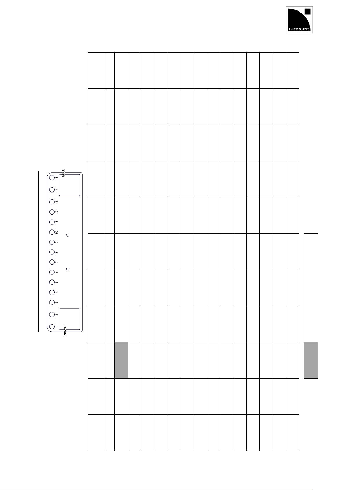
Tilt angle reference chart WIFOBUMP (homogeneous arrays)
8 ARCS
®
WIDE
71,8°
71,1°
70,3°
69,6°
68,8°
68,0°
67,2°
66,2°
65,2°
64,1°
62,9°
61,7°
60,2°
58,4°
56,3°
8 ARCS
®
FOCUS
43,8°
42,7°
41,6°
40,6°
39,6°
38,6°
37,6°
36,5°
35,4°
34,3°
33,1°
32,0°
30,7°
29,2°
27,6°
6ARCS
®
WIDE
60,0°
58,7°
57,4°
56,2°
54,9°
53,6°
52,2°
50,6°
49,0°
47,2°
45,3°
43,3°
41,1°
38,3°
35,3°
6 ARCS
®
FOCUS
60,0°
58,7°
57,4°
56,2°
54,9°
53,6°
52,2°
50,6°
49,0°
47,2°
45,3°
43,3°
41,1°
38,3°
35,3°
4 ARCS
®
WIDE
48,1°
46,0°
43,8°
41,8°
39,7°
37,5°
35,1°
32,5°
29,8°
27,0°
23,9°
20,8°
17,5°
13,4°
9,1°
4 ARCS
®
FOCUS
32,3°
30,1°
27,8°
25,8°
23,7°
21,6°
19,4°
17,1°
14,8°
12,4°
10,0°
7,6°
5,1°
2,1°
-1,0°
= not applicable with the CLAMP250
2 ARCS
®
WIDE
43,0°
39,3°
35,2°
31,4°
27,2°
22,8°
18,0°
12,9°
7,7°
2,3°
-3,2°
-8,5°
-13,8°
-19,8°
-25,4°
2 ARCS
®
FOCUS
35,4°
31,6°
27,4°
23,8°
19,9°
15,8°
11,5°
7,1°
2,6°
-1,9°
-6,4°
-10,8°
-15,1°
-20,1°
-24,7°
1 ARCS
®
WIDE
51,4°
46,6°
40,7°
34,9°
28,2°
20,5°
11,9°
2,8°
-6,5°
-15,4°
-23,7°
-31,0°
-37,3°
-43,8°
-49,1°
1 ARCS
®
FOCUS
47,9°
43,0°
37,1°
31,5°
25,1°
17,9°
10,2°
2,0°
-6,2°
-14,2°
-21,7°
-28,4°
-34,5°
-40,7°
-46,0°
WIFOBUMP
hole
1 2 3 4 5 6 7 8 9
10
11
12
13
14
15
Page 30
ARCS
®
WIDE SYSTEM / ARCS
®
FOCUS SYSTEM
rigging manual
VERSION 3.0
ARCSWIFO_RM_EN_3.0 w w w . l - a c o u s t i c s . c o m 30
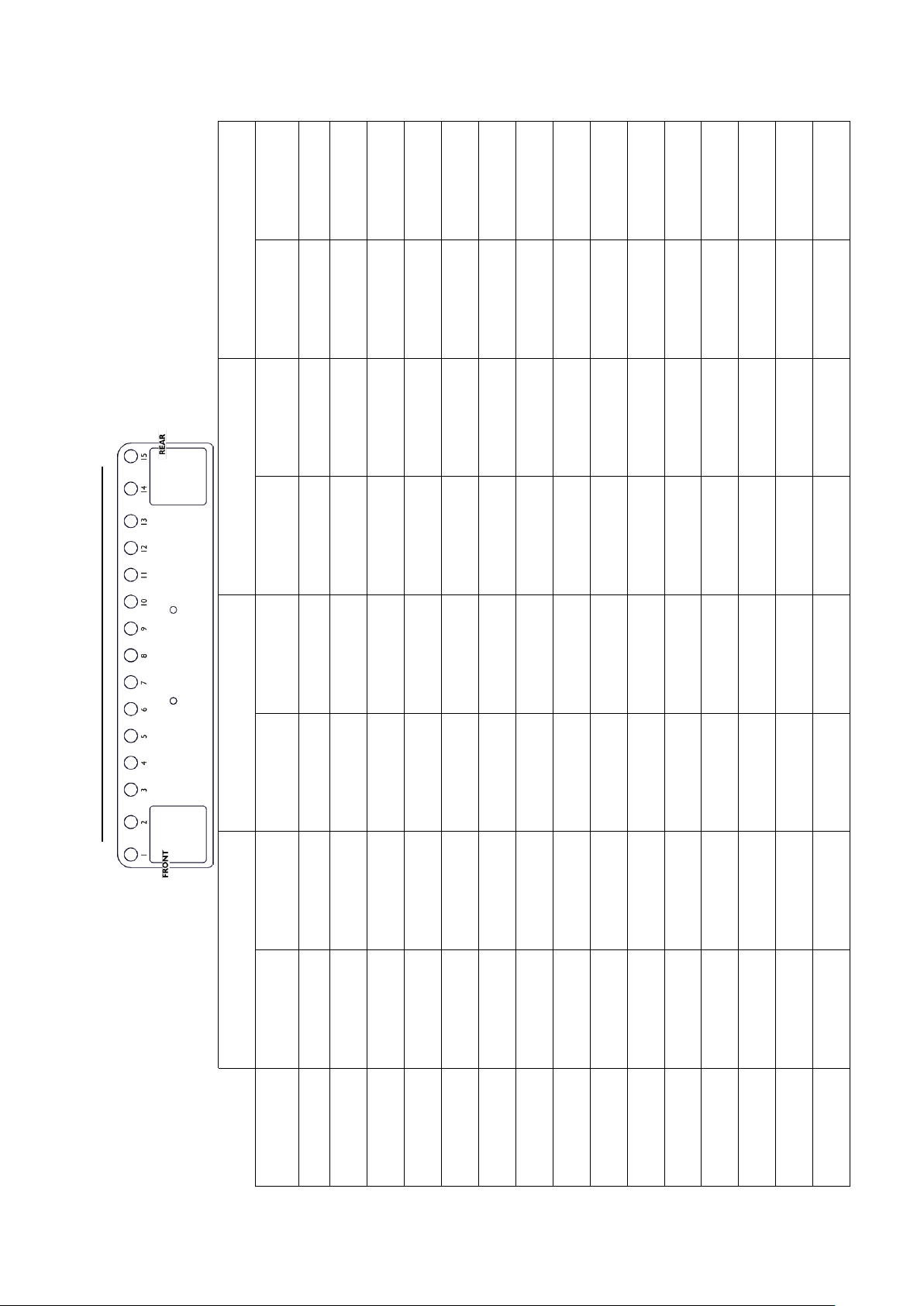
Tilt angle reference chart WIFOBUMP (hybrid arrays)
1 SB18m and 2 ARCS
®
WIDE
Rear position
2,4°
-0,8°
-3,9°
-6,6°
-9,1°
-11,7°
-14,2°
-16,6°
-19,0°
-21,3°
-23,6°
-25,8°
-27,9°
-30,3°
-32,6°
Front position
26,6°
24,0°
21,3°
19,0°
16,6°
14,2°
11,7°
9,1°
6,5°
3,9°
1,3°
-1,3°
-3,9°
-7,1°
-10,2°
1 SB18m and 2 ARCS
®
FOCUS
Rear position
0,9°
-2,1°
-5,0°
-7,5°
-9,9°
-12,2°
-14,6°
-16,9°
-19,1°
-21,3°
-23,4°
-25,4°
-27,4°
-29,7°
-31,9°
Front position
24,1°
21,5°
18,9°
16,7°
14,4°
12,1°
9,7°
7,3°
4,8°
2,4°
-0,1°
-2,6°
-5,0°
-8,0°
-10,9°
2 SB18m and 4 ARCS
®
WIDE
Rear position
7,3°
5,6°
3,9°
2,4°
1,0°
-0,4°
-1,8°
-3,3°
-4,7°
-6,1°
-7,5°
-8,9°
-10,3°
-12,0°
-13,6°
Front position
20,7°
19,1°
17,6°
16,3°
15,0°
13,6°
12,3°
10,9°
9,5°
8,1°
6,7°
5,3°
3,9°
2,1°
0,4°
2 SB18m and 4 ARCS
®
FOCUS
Rear position
4,5°
3,0°
1,4°
0,1°
-1,1°
-2,4°
-3,7°
-5,0°
-6,3°
-7,5°
-8,8°
-10,0°
-11,3°
-12,7°
-14,2°
Front position
16,8°
15,4°
14,0°
12,8°
11,5°
10,3°
9,0°
7,8°
6,5°
5,3°
4,0°
2,7°
1,4°
-0,1°
-1,7°
WIFOBUMP
hole
1 2 3 4 5 6 7 8 9
10
11
12
13
14
15
Page 31
ARCSWIFO_RM_EN_3.0 w w w . l - a c o u s t i c s . c o m 31
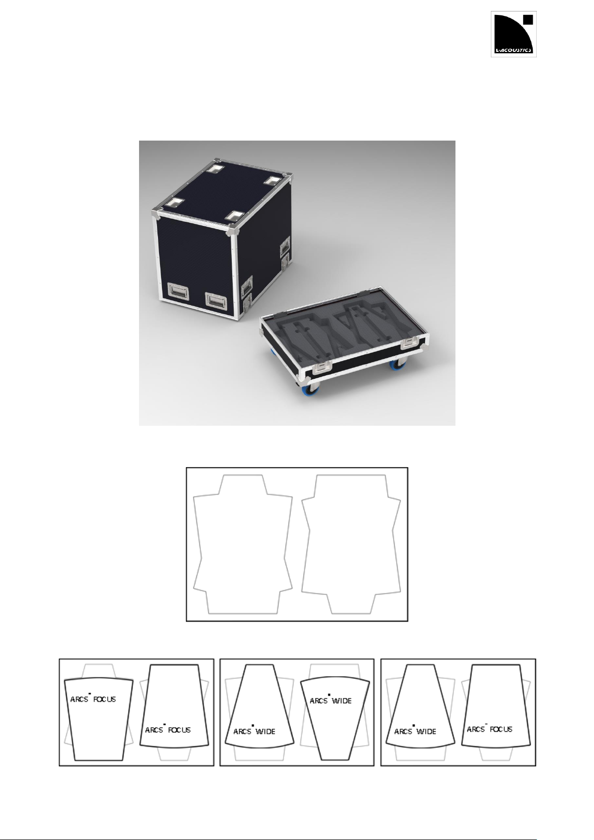
APPENDIX C RECOMMENDED FLIGHT-CASE
It is recommended to use a dedicated flight-case capable to fit 2 ARCS® WIDE/FOCUS enclosures in vertical position.
Both the tray and cap should feature a foam insert cut according to the pattern illustrated below. This one allows for
the different enclosure combinations: 2 ARCS® WIDE, 2 ARCS® FOCUS or 1 ARCS® WIDE / 1 ARCS® FOCUS.
Cap and tray of the flight-case
Pattern of the foam insert for the cap and the tray
Storage options
Page 32
ARCS
®
WIDE SYSTEM / ARCS
®
FOCUS SYSTEM
rigging manual
VERSION 3.0
ARCSWIFO_RM_EN_3.0 w w w . l - a c o u s t i c s . c o m 32
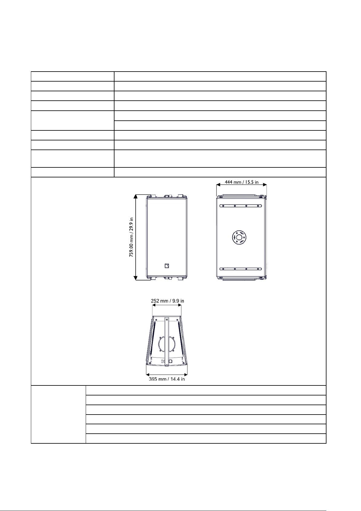
Description
2-way passive enclosure, amplified by LA4 or LA8
Usable bandwidth (-10 dB)
55 Hz - 20 kHz ([ARCS_WIFO] preset)
Maximum SPL1
137 dB ([ARCS_WIFO] preset)
Coverage angle (-6 dB)
15° 90°
Transducers
LF 1 3" diaphragm compression driver, DOSC® waveguide.
HF 1 12" , weather-resistant, bass-reflex.
Nominal impedance
LF = 8 Ω
RMS power handling
450 W
Connectors
IN: 1 4-point SpeakOn®
LINK: 1 4-point SpeakOn®
Rigging components
Rigging rails and WIFORIG rigging bars.
Dimensions
Physical data
Weight (net):
38 kg / 84 lb
Cabinet:
Baltic birch plywood.
Finish:
Grey brown RAL 8019® or Pure white RAL 9010®
Front:
Steel grill with anti-corrosion coating, Airnet® fabric
Protection Rating:
IP45
Rigging component:
High strength steel with anti-corrosion coating
APPENDIX D SPECIFICATIONS
ARCS® FOCUS
1
Peak level at 1 m under free field conditions using 10 dB crest factor pink noise with specified preset.
Page 33
ARCSWIFO_RM_EN_3.0 w w w . l - a c o u s t i c s . c o m 33
ARCS® WIDE
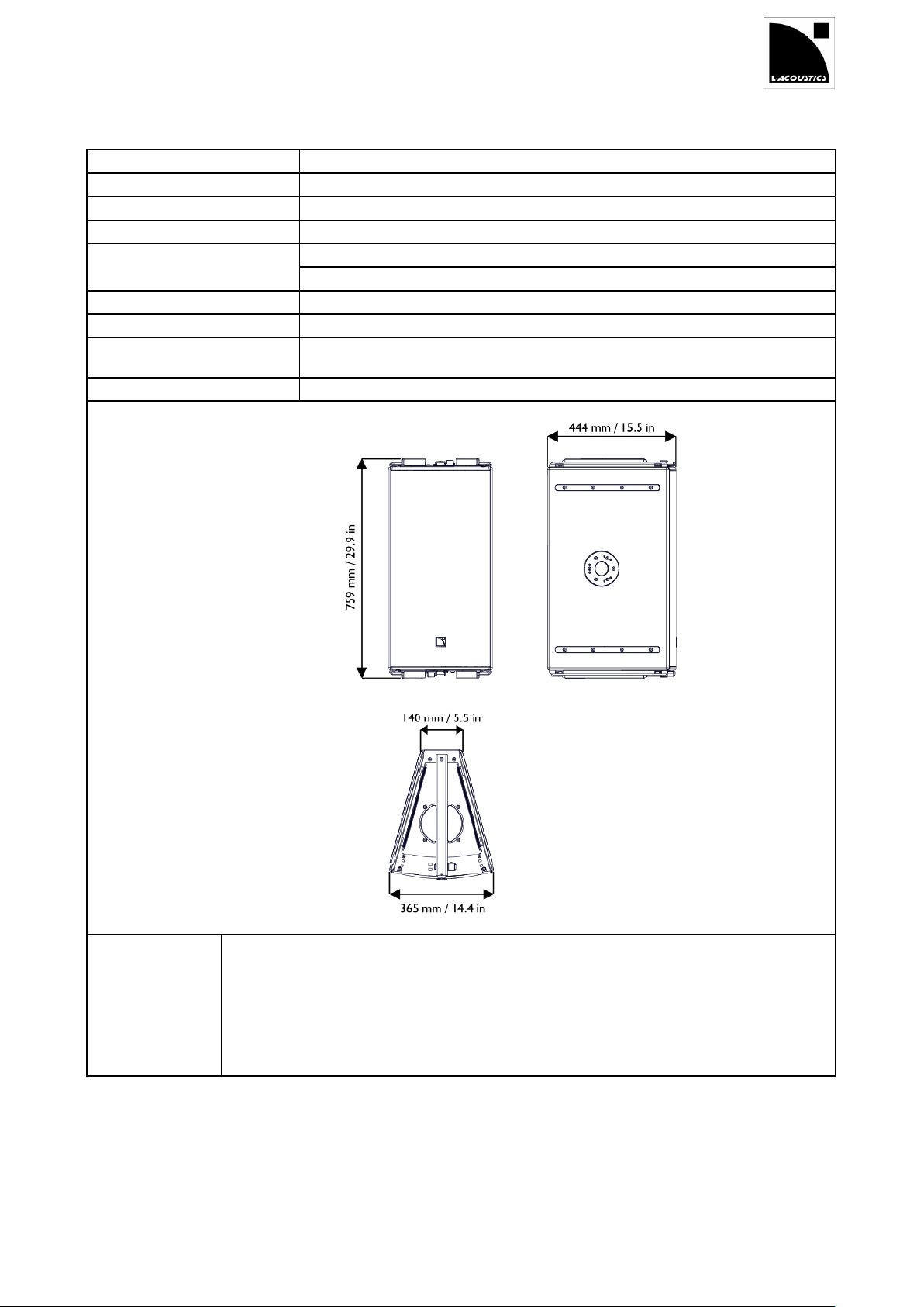
Description
2-way passive enclosure, amplified by LA4 or LA8
Usable bandwidth (-10 dB)
55 Hz - 20 kHz ([ARCS_WIFO] preset)
Maximum SPL1
135 dB ([ARCS_WIFO] preset)
Coverage angle (-6 dB)
30° 90°
Transducers
LF 1 3" diaphragm compression driver, DOSC® waveguide.
HF 1 12" , weather-resistant, bass-reflex.
Nominal impedance
8 Ω
RMS power handling
450 W
Connectors
IN: 1 4-point SpeakOn®
LINK: 1 4-point SpeakOn®
Rigging components
Rigging rails and WIFORIG rigging bars.
Dimensions
Physical data
Weight (net):
38 kg / 84 lb
Cabinet:
Baltic birch plywood.
Finish:
Grey brown RAL 8019® or Pure white RAL 9010®
Front:
Steel grill with anti-corrosion coating, Airnet® fabric
Protection Rating:
IP45
Rigging component:
High strength steel with anti-corrosion coating
1
Peak level at 1 m under free field conditions using 10 dB crest factor pink noise with specified preset.
Page 34
ARCS
®
WIDE SYSTEM / ARCS
®
FOCUS SYSTEM
rigging manual
VERSION 3.0
ARCSWIFO_RM_EN_3.0 w w w . l - a c o u s t i c s . c o m 34
SB18m
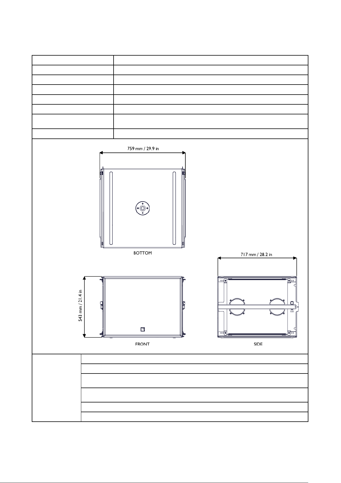
Description
Subwoofer enclosure, amplified by LA4 or LA8
Low frequency limit (-10 dB)
32 Hz ([SB18_100] preset)
Maximum SPL1
136 dB ([SB18] preset)
RMS power handling
700 W
Transducers
1 18" weather resistant, dual bass-reflex
Nominal impedance
8 Ω
Connectors
IN: 1 4-point SpeakOn®
LINK: 1 4-point SpeakOn®
Rigging components
Rigging rails and two SB18RIG rigging bars.
Dimensions
Physical data
Weight (net):
62 kg/137 lbs
Cabinet:
Baltic birch plywood
Finish:
Grey brown, RAL 8019® or Pure white, RAL 9010®
RAL code on special order
Front:
Steel grill with anti-corrosion coating
Airnet® acoustically neutral fabric
Protection Rating:
IP45
Rigging component:
High strength steel
1
Peak level at 1 m under half-space conditions using 10 dB crest factor pink noise with specified preset.
Page 35
ARCSWIFO_RM_EN_3.0 w w w . l - a c o u s t i c s . c o m 35
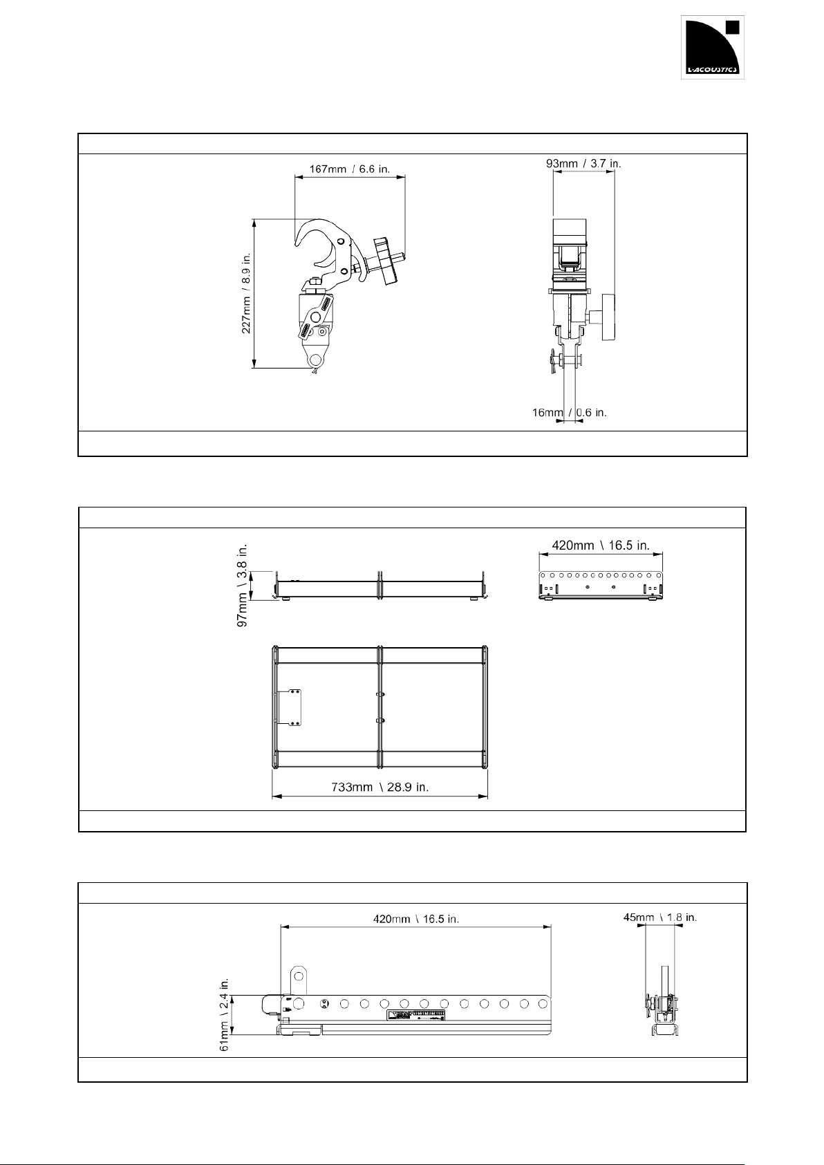
CLAMP250
Description
Rigging element
Dimensions
Weight
1,8 kg / 4 lb
Material
Steel with anti-corrosion coating
Description
Rigging element for the ARCS® WIDE SYSTEM and the ARCS® FOCUS SYSTEM
Dimensions
Weight
10,5 kg / 23.1 lb
Material
Steel with anti-corrosion coating
Description
Rigging element for the ARCS® WIDE SYSTEM and the ARCS® FOCUS SYSTEM
Dimensions
Weight
2 kg / 4.4 lb
Material
Steel with anti-corrosion coating
WIFOBUMP
WIFOLIFT
Page 36
ARCS
®
WIDE SYSTEM / ARCS
®
FOCUS SYSTEM
rigging manual
VERSION 3.0
ARCSWIFO_RM_EN_3.0 w w w . l - a c o u s t i c s . c o m 36
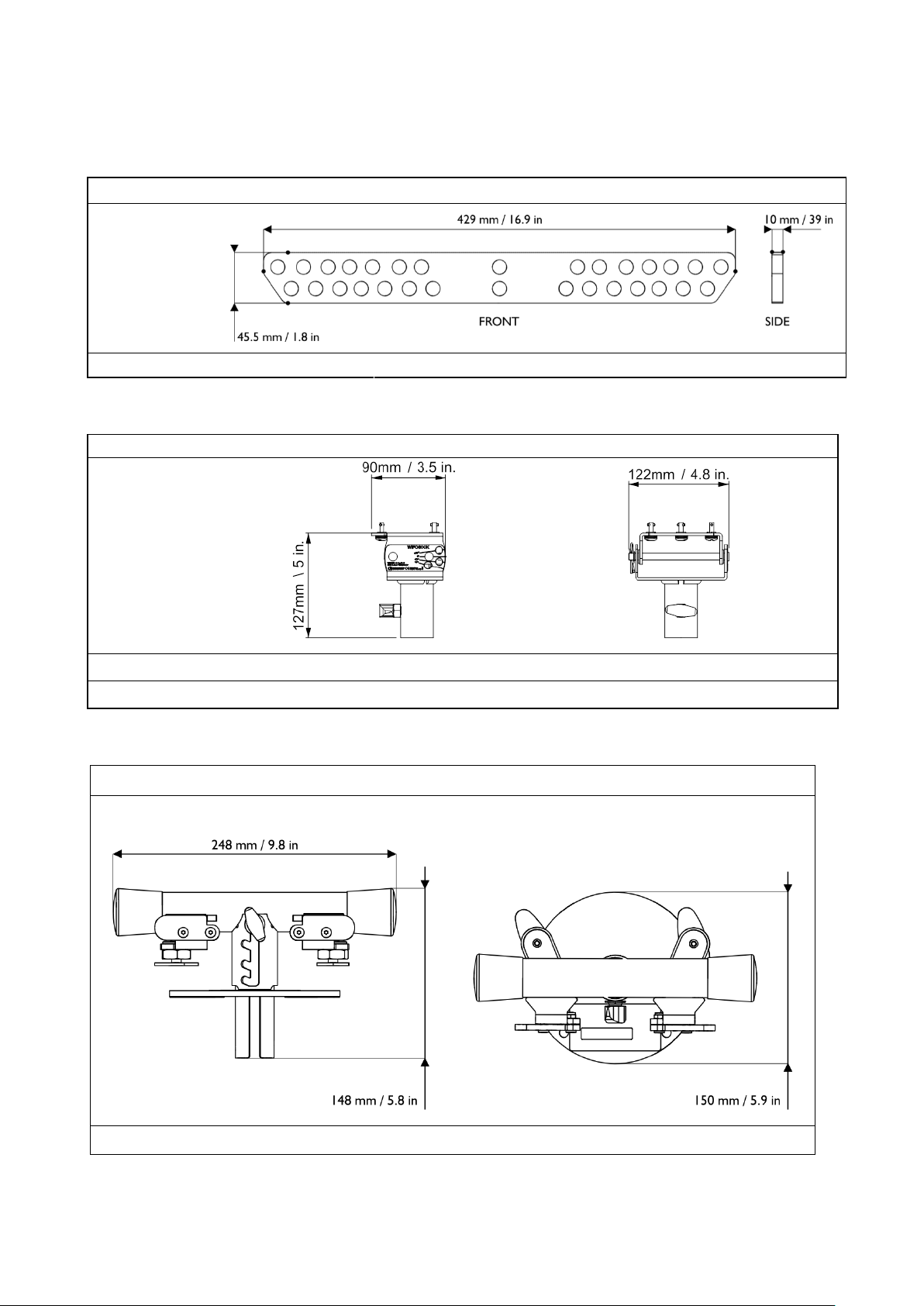
Description
Rigging element for the ARCS® WIDE and ARCS® FOCUS enclosure
Dimensions
Weight
1.6 kg
Material
High-grade steel with anti-corrosion coating
Description
Rigging element for the ARCS® WIDE SYSTEM and the ARCS® FOCUS SYSTEM
Dimensions
Weight
0,8 kg / 1.8 lb
Material
Steel with anti-corrosion coating
Description
Accessory used to stack up to 4 ARCS WIFO on SB18m and set their site angle.
Dimensions
Weight
2.1 kg / 4.6 lb
Material
Steel with anti-corrosion coating
WIFOLIFTBAR
WIFOSOCK
WIFOTILT
Page 37

Document reference: ARCSWIFO_RM_EN_3.0
Distribution date: August 4, 2014
© 2014 L-ACOUSTICS®. All rights reserved.
No part of this publication may be reproduced or transmitted in any form
or by any means without the express written consent of the publisher.
 Loading...