

Page 1
4-Disk RAID
USB 2.0, FireWire 800/400, eSATA
user manual
manuel utilisateur
manual de instrucciones
gebruikershandleiding
guída utente
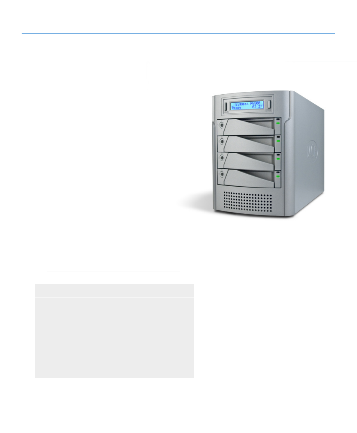
Biggest Quadra
handbuch
ユーザー マニュアル
用户手册
용자 설명서
Page 2

LaCie Biggest Quadra
User Manual
Table of Contents
Health and Safety Precautions 4
General Use Precautions 4
Table of Contents
page 1
1. Introduction to the LaCie Biggest Quadra
2. About the LaCie Biggest Quadra 7
2.1. Minimum System Requirements 7
2.2. Package Content 8
2.3. Specifications 9
2.4. Views of the Drive 10
2.4.1. Front View 10
2.4.2. Rear View 11
2.5. Cables and Connectors 12
2.5.1. FireWire 400 and 800 Cables and Connectors 12
2.5.2. Hi-Speed USB 2.0 Cables and Connectors 13
2.5.3. eSATA Cables and Connectors 14
2.6. Drive Tray Locks 15
3. Understanding RAID 1
3.1. RAID 0 16
3.2. RAID 0 + 1 17
3.3. RAID 5 18
3.4. RAID 5 + Hot Spare 19
4. Setting Up Your LaCie Biggest Quadra 2
4.1. Setting the RAID Level 21
4.1.1. RAID 5 22
4.1.2. RAID 5 + Hot Spare 22
4.1.3. RAID 0 23
4.1.4. RAID 0 + 1 23
4.2. Creating an Array 24
4.2.1. Initializing the Disks 24
4.2.2. Managing Volumes over 2TB in Windows 26
4.3. Connecting to a Host Computer 27
4.3.1. Connecting to the Host Computer via FireWire 28
4.3.2. Connecting to the Host Computer via Hi-Speed USB 2.0 29
4.3.3. Connecting to the Host Computer via eSATA 3
4.4. Setting the LCD Display Time & Date 31
4.5. Formatting and Partitioning 32
4.5.1. Windows Users 32
4.5.2. Mac Users 34
6
6
0
0
Page 3

LaCie Biggest Quadra
User Manual
5. Using the LaCie Biggest Quadra 35
5.1. Disk Status and Activity Indicators 35
5.2. LCD Display Messages 36
5.2.1. Initialization Messages 36
5.2.2. Rebuild Messages 37
5.2.3. Failure and Error Messages 38
5.2.4. RAID and Disk Status Messages 39
5.2.5. RAID and Disk Information Messages 40
6. Maintaining Your LaCie Biggest Quadra 42
6.1. Removing/Replacing A Drive 42
6.2. Firmware Updates 42
7. Technical Information 43
7.1. File System Formats 43
7.2. Available Storage Capacity 45
7.3. Optimizing Data Transfers 45
Table of Contents
page 2
8. FireWire Questions & Answers 48
9. USB Questions & Answers 50
10. eSATA Questions & Answers 52
11. Troubleshooting 54
12. Contacting Customer Support 56
12.1. LaCie Technical Support Contacts 57
13. Warranty Information 58
Page 4
LaCie Biggest Quadra
User Manual
Copyrights
Copyright © 2007 LaCie. All rights reserved. No part of this publication may
be reproduced, stored in a retrieval system, or transmitted in any form or by
any means, electronic, mechanical, photocopying, recording or otherwise, without the prior written consent of LaCie.
Trademarks
Apple, Mac, Macintosh and FireWire
are registered trademarks of Apple
Computer, Inc. Microsoft, Windows
NT, Windows 98, Windows 98 SE,
Windows 2000, Windows Millennium
Edition, Windows Server 2003, Windows XP and Windows Vista are registered trademarks of Microsoft Corporation. Sony and iLink are registered
trademarks of Sony Electronics. Other
trademarks mentioned in this manual
are the property of their respective owners.
Changes
e material in this document is for information only and subject to change
without notice. While reasonable efforts have been made in the preparation
of this document to assure its accuracy,
LaCie assumes no liability resulting
from errors or omissions in this document, or from the use of the information contained herein. LaCie reserves
the right to make changes or revisions
in the product design or the product
manual without reservation and without
obligation to notify any person of such
revisions and changes.
LaCie Biggest Quadra
Tested To Comply
With FCC standards
FOR HOME OR
OFFICE USE
FCC Statement
is device complies with Part 15 of the
FCC Rules. Operation is subject to the
following conditions:
1. e devices may not cause harmful
interference
2. e devices must accept any interference received, including interference
that may cause undesired operation
NOTE: is equipment has been tested
and found to comply with the limits for
a Class B digital device, pursuant to Part
15 of the FCC Rules. ese limits are
designed to provide reasonable protection against harmful interference in a
residential installation. is equipment
generates, uses and can radiate radio
frequency energy and, if not installed
and used in accordance with the instructions, may cause harmful interference to
radio communications. However, there
is no guarantee that interference will
not occur in a particular installation. If
this equipment does cause harmful interference to radio or television reception, which can be determined by turning the equipment off and on, the user is
encouraged to try and correct the interference by one or more of the following
measures:
Reorient or relocate the receiving an-
❖
tenna.
Increase the separation between the
❖
equipment and receiver.
Forward
page 3
Connect the equipment into an out-
❖
let on a circuit different from that to
which the receiver is connected.
Consult the dealer or an experienced
❖
radio/TV technician for help.
Modifications to this product not
authorized by LaCie could void the
FCC & Industry Canada regulations
and negate your authority to operate the
product.
Canada Compliance Statement
is Class B digital apparatus complies with Canadian ICES-003.
Manufacturer’s Declaration for CE Certification
We, LaCie, solemnly declare that this
product conforms to the following European standards:
Class B EN60950-1:2003, EN55022:
1998, EN55024:1998 +A1, EN610003-2: 2000, EN61000-3-3:2001
With reference to the following conditions:
73/23/EEC Low Voltage Directive
89/336/EEC EMC Directive
Page 5
LaCie Biggest Quadra
User Manual
Forward
page 4
is symbol on the product or on its packaging
indicates that this product
must not be disposed of
with your other household waste. Instead, it is your responsibility to dispose
of your waste equipment by handing it
over to a collection point for the recycling of electrical and electronic equip-
ment. e collection and recycling of
your waste equipment at the time of
disposal will help to conserve resources
and ensure that it is recycled in a way
that protects health and the environment. For information about where
you can drop off your equipment for
recycling, please contact your city waste
disposal service.
Health and Safety Precautions
Only qualified persons are authorized to
carry out maintenance on this device.
• Read this User’s Guide carefully, and
follow the correct procedure when setting up the device.
• Do not open your LaCie Biggest
Quadra or attempt to disassemble or
modify it. Never insert any metallic object into the drive to avoid any risk of
electrical shock, fire, short-circuiting or
dangerous emissions. Your LaCie Big-
gest Quadra contains no user-serviceable
parts. If it appears to be malfunctioning,
have it inspected by a qualified LaCie
Technical Support representative.
• Never expose your device to rain, or
use it near water, or in damp or wet conditions. Never place objects containing
liquids on the LaCie Biggest Quadra, as
they may spill into its openings. Doing
so increases the risk of electrical shock,
short-circuiting, fire or personal injury.
CAUTION: A shielded-type
power cord is required in order
to meet FCC emission limits and
also to prevent interference to the
nearby radio and television reception. It is essential that only the
supplied power cord be used.
• Make sure that the computer and
LaCie Biggest Quadra are electrically
grounded. If the devices are not grounded, there is an increased risk of electrical shock.Power requirements 100-240
V~, 4-2 A, 60-50 Hz, (Supply voltage
fluctuations not exceeding ± 10% of the
nominal, transient over-voltages according to over-voltage category II).
General Use Precautions
Do not expose the LaCie Biggest
❖ cold or humid may damage the unit.
Quadra to temperatures outside
the range of 0° C to 35° C (32° F
to 95° F); or to operational humidity beyond 5-95%, non-condensing,
or non-operating humidity beyond
5-95%, non-condensing. Doing
so may damage the LaCie Biggest
Quadra or disfigure its casing. Avoid
placing your LaCie Biggest Quadra
near a source of heat or exposing it
to sunlight (even through a window).
Inversely, placing your LaCie Biggest
Quadra in an environment that is too
Rated cooling for altitudes up to
❖
2000 meters.
Always unplug the LaCie Biggest
❖
Quadra from the electrical outlet if
there is a risk of lightning or if it will
be unused for an extended period of
time. Otherwise, there is an increased
risk of electrical shock, short-circuiting or fire.
Use only the power supply shipped
❖
with the device.
Do not use the LaCie Biggest Quadra
❖
near other electrical appliances such
as televisions, radios or speakers. Doing so may cause interference which
will adversely affect the operation of
the other products.
Do not place the LaCie Biggest
❖
Quadra near sources of magnetic interference, such as computer displays,
televisions or speakers. Magnetic interference can affect the operation
and stability of your LaCie Biggest
Quadra.
Page 6
LaCie Biggest Quadra
Forward
User Manual
Do not place heavy objects on top of
❖
the LaCie Biggest Quadra or use excessive force on it.
Never use excessive force on your
❖
LaCie Biggest Quadra. If you detect
a problem, consult the Troubleshooting section in this manual.
Protect your LaCie Biggest Quadra
❖
from excessive exposure to dust dur-
ImpOrTANT INfO: Any loss, corruption or destruction of data while using a LaCie drive is the sole responsibility of the
user, and under no circumstances will LaCie be held liable for the recovery or restoration of this data. To help prevent the loss
of your data, LaCie highly recommends that you keep TWO copies of your data; one copy on your external hard drive, for
instance, and a second copy either on your internal hard drive, another external hard drive or some other form of removable
storage media, such as CD, DVD or Tape. LaCie offers a complete line of CD, DVD and Tape drives, and if you would like
more information on backup, please refer to the LaCie white paper on backup methods and technology.
ing use or storage. Dust can build up
inside the device, increasing the risk
of damage or malfunction.
Never use benzene, paint thinners,
❖
detergent or other chemical products to clean the outside of the LaCie Biggest Quadra. Such products
will disfigure and discolor the casing.
Instead, use a soft, dry cloth to wipe
the device.
Do not attempt to remove a hard
❖
disk from a drive tray. Removal of
a hard disk by anyone other than an
authorized LaCie Technical Support
representative will void the warranty.
CAUTION: Modifications not
authorized by the manufacturer
may void the user’s authority to
operate this device.
page 5
ImpOrTANT INfO: 1GB = 1,000,000,000 bytes. 1TB = 1,000,000,000,000 bytes. Once formatted, the actual available
storage capacity varies depending on operating environment (typically 5-10% less).
Page 7
LaCie Biggest Quadra
User Manual
1. Introduction to the LaCie Biggest Quadra
Congratulations on the purchase of your new
LaCie Biggest Quadra. is high-performance, extremely flexible RAID (Redundant Array of Independent/Inexpensive Disks) subsystem is ideally suited for
integration with databases, imaging systems and e-mail
and Web servers.
RAID technology is one of the best means to protect your data, while providing greater performance,
data integrity and availability than standard hard disk
storage. With single error detection and disk parity used
to recover data if a disk fails, a RAID system ideal for
safeguarding valuable data while streamlining performance.
Introduction
page 6
e LaCie Biggest Quadra is the ultimate approach
to a flexible RAID solution, managing three different
RAID levels (0, 0+1 and 5) and offering the option of
RAID 5 + hot spare. Featuring intelligent online recovery, the LaCie Biggest Quadra allows one drive to
be designated a hot spare – if one drive fails, the LaCie
Biggest Quadra will seamlessly rebuild the failed drive’s
data on the hot spare.
Biggest Quadra Features■
Supports powerful RAID 0, 0+1, 5, and RAID 5+spare
❖
Hot swappable SATA disk drives for security and recovery
❖
eSATA 1.5 Gbits/s interface
❖
Automatic on-line rebuilding (RAID 0+1, 5, 5+)
❖
Event notification through audible alarm
❖
LCD panel for operational status display
❖
Page 8
LaCie Biggest Quadra
User Manual
2. About the LaCie Biggest Quadra
2.1. Minimum System Requirements
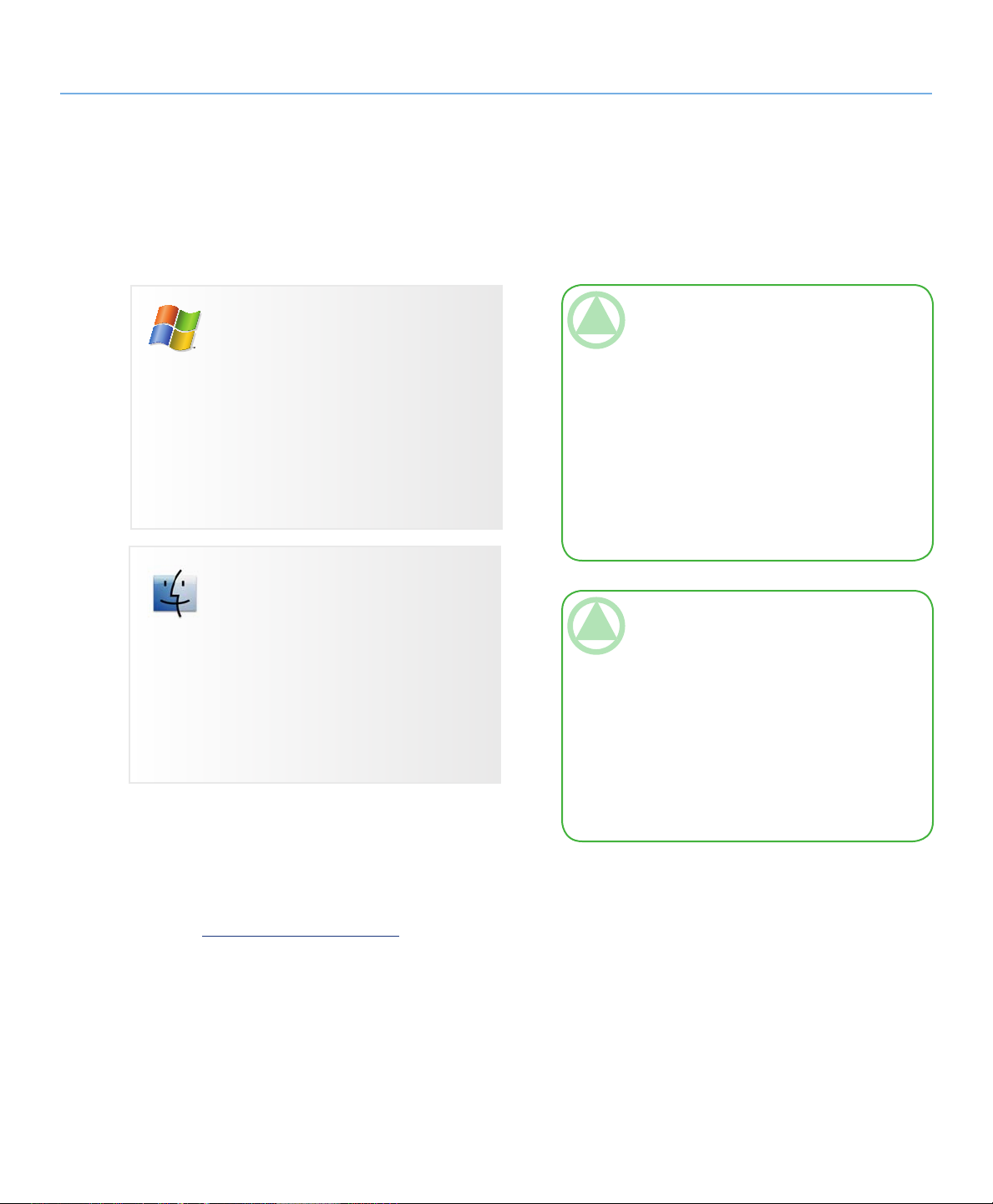
Windows Users
Pentium III or higher compatible processor
❖
128MB RAM or greater
❖
Windows 2000, Windows Server 2003, Win-
❖
dows XP or Windows Vista
Available eSATA*, USB 2.0, FireWire 400 or
❖
FireWire 800* interface port
About the LaCie Biggest Quadra
page 7
TeChNICAl NOTe: Windows 2000 Users! In
order for the LaCie Biggest Quadra to be recognized by your computer using the FireWire/IEEE
1394 interface, you must have Windows Service
Pack 3 installed on your operating system. To ensure that you have the correct configuration, right
click on My Computer and select Properties. e
System Properties dialog box will appear. Click on
the General tab and this will list which version of
the Windows operating system you are currently
running.
Mac Users
G3 and later or Intel Core processor
❖
128MB RAM or greater
❖
Mac OS 10.2.8 or later
❖
Available eSATA*, USB 2.0, FireWire 400 or
❖
FireWire 800* interface port
* Most computers do not come from the factory with FireWire
800 or eSATA ports, so you may need to purchase a PCI,
PCI-X or PCI-Express card to be able to connect your Biggest Quadra via these interfaces. LaCie offers a wide selection of eSATA and FireWire 800 cards. Visit the LaCie
website at www.lacie.com/accessories
TeChNICAl NOTe: Mac Users! USB Con-
nectivity: For optimal performance under the Mac
OS, it is recommended that you use the FireWire
interface unless you are using a G5 or are running Mac OS 10.2.8 or later on a computer with a
Hi-Speed USB 2.0 PC or PCI card. All versions
of the Mac OS before Mac OS 10.2.8 do not
support the transfer rates of Hi-Speed USB 2.0,
and all data transfers will be made at the slower
USB 1.1 rates.
Page 9
LaCie Biggest Quadra
Quick Install Guide
Biggest FW800
©
2
0
0
6
L
a
C
i
e
,
a
l
l
r
i
g
h
t
s
r
e
s
e
r
v
e
d
.
7
1
0
9
2
4
0
6
0
9
0
5
Biggest FW800
User Manual & Utilities
version1.0
SATA
SATA
User Manual
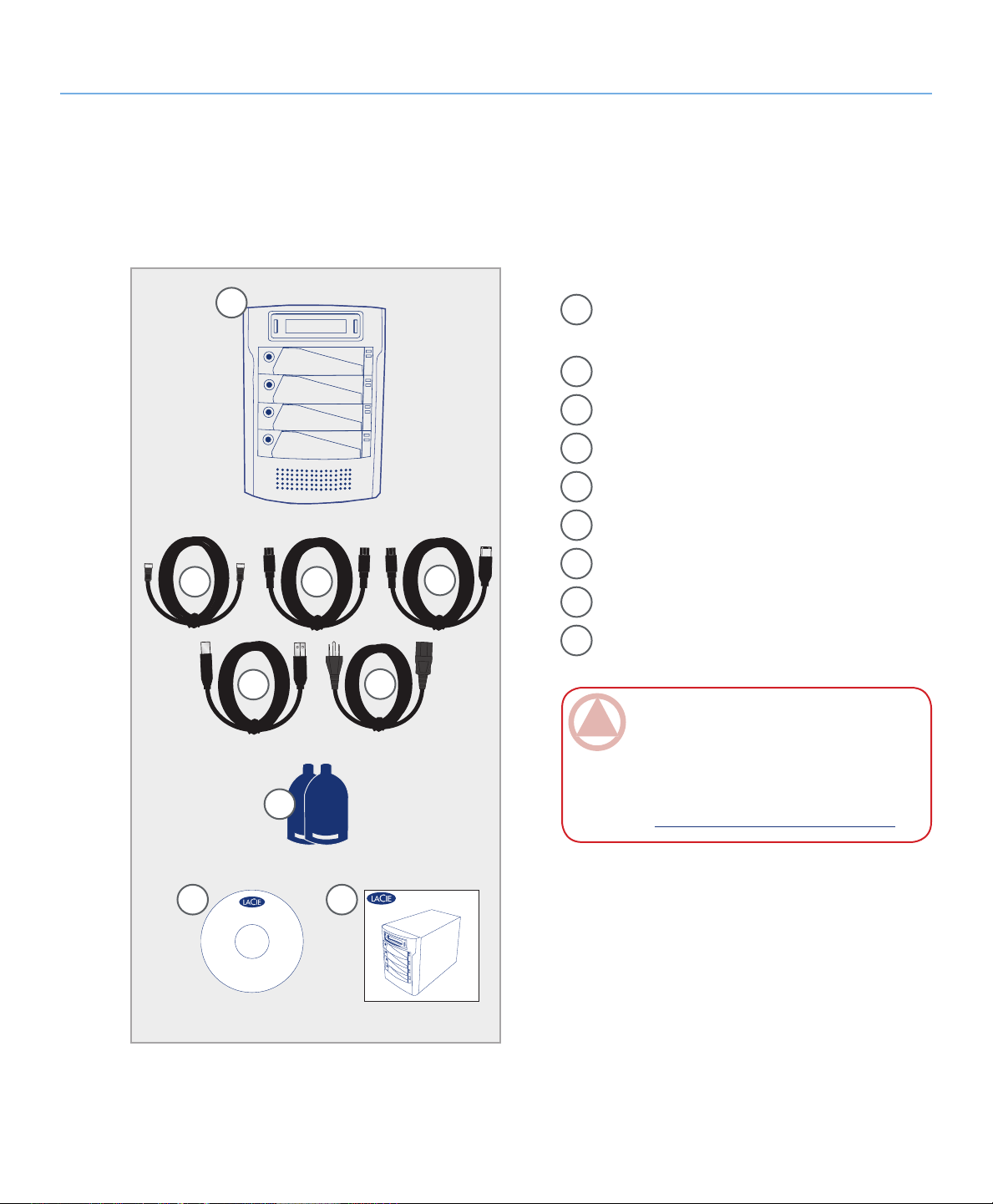
2.2. Package Content
Your LaCie hard drive package should contain the
following:
About the LaCie Biggest Quadra
page 8
1
LaCie Biggest Quadra RAID with 4 SATA hard
1
disks
eSATA cable
2
FireWire 800 9-to-9-pin cable
3
FireWire 800/400 9-to-6-pin cable
4
Hi-Speed USB 2.0 cable
5
Power cable
6
Drive lock keys (2)
2
5
3
6
4
7
LaCie Utilities CD-ROM
8
Quick Install Guide
9
ImpOrTANT INfO: Please save your packag-
ing. In the event that the drive should need to be
repaired or serviced, it must be returned in its original packaging. In the event that an individual disk
7
should need to be repaired or serviced, please refer
to section 6.1. Removing or Replacing a Drive.
8
9
Page 10

LaCie Biggest Quadra
User Manual
2.3. Specifications
Host Interface■
eSATA, FireWire 400, FireWire 800 and USB 2.0❖
Weight and Dimensions■
25.3 lbs/11.5 Kgw
❖
152.8 x 206.4 x 268.5 mm
❖
Operation Temperature■
0 - 35°C❖
About the LaCie Biggest Quadra
page 9
Operation Humidity■
5 - 95%, non condensing❖
Storage Humidity■
5 - 95%, non-condensing❖
Power Supply■
200W; input 100~250V AC; output +5V/10A,
❖
+12V/10A, +3.3V/5A
Available Capacity■
RAID 0 = 100%
❖
RAID 0+1= 50%
❖
RAID 5 = 75%
❖
RAID 5+ Spare = 50%
❖
Page 11
LaCie Biggest Quadra
User Manual
2.4. Views of the Drive
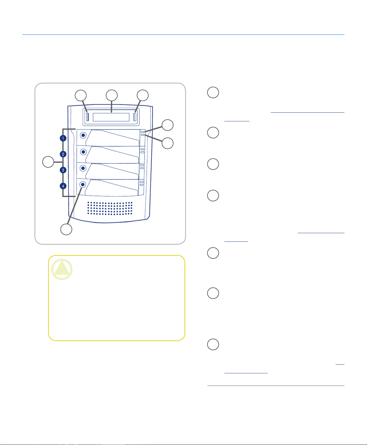
2.4.1. Front View■
5
Disk
Disk
4 3
About the LaCie Biggest Quadra
page 10
Disk Activity Indicator – Indicates when the
1
disk is being accessed. For more information,
please see section 5.1. Disk Status and Activity
Indicators.
2
Disk Status Indicator – Indicates the status of
2
1
the disk. For more information, please see section
5.1. Disk Status And Activity Indicators.
6
Disk
Disk
7
CAUTION: To avoid overheating, the LaCie
Biggest Quadra should be installed in a well-ven-
tilated area and in such a way as to maintain suf-
ficient airflow across the controller chips. Also en-
sure that the Ventilation Fan is not obstructed.
Environmental Requirements:
Temperature: 0 – 35° C (32 – 95° F)
Operation Humidity: 5 – 95%, non-condensing
Storage Humidity: 5 – 95%, non-condensing
Fig. 2.4.1.
Enter/Mute Button – e enter button is used
3
to set the date and time, and is also used to mute
the alert buzzer.
LCD Display – e LCD Display alerts you to
4
the status and configuration information of your
LaCie Biggest Quadra’s subsystem and arrays.
For more information about the LCD Display
messages, please see section 5.2. LCD Display
Messages.
Scroll Button – e scroll button is used to navi-
5
gate through the information on the LCD Display, and is used to select settings for setting the
date and time.
Drive Trays – Each drive tray can hold one-inch
6
high, 3.5-inch SATA disk drive.
Disk 1 – is is also the default Hot Spare Disk.
Disks 2 – 4
Drive Locks – Protect your Biggest Quadra’s
7
drives from accidental removal and damage by
locking the drives into their bays. See section 2.6.
Drive Tray Locks.
Page 12
LaCie Biggest Quadra
USB
eSATA
0 5 0-1 5-S
User Manual
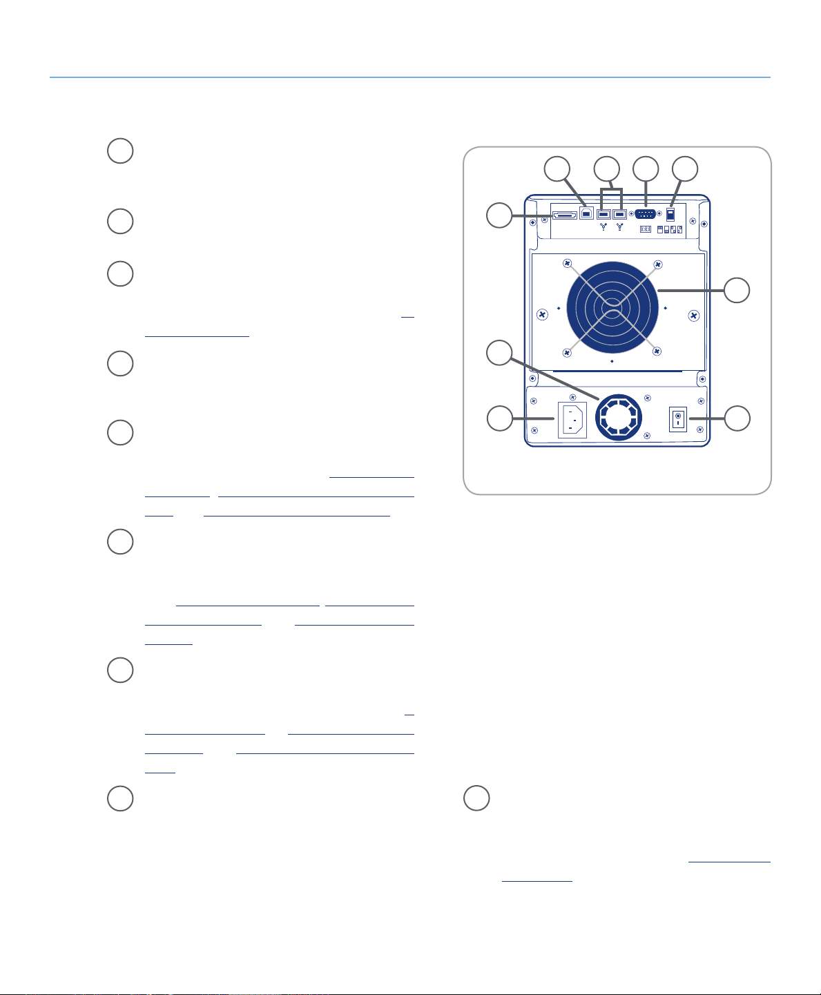
2.4.2. Rear View■
Ventilation Fan – e ventilation fan keeps your
1
drive cool during operation. Be sure not to block
the fan when using your drive.
About the LaCie Biggest Quadra
page 11
6
8 97
Power Switch – e power svwitch is the main
2
on/off switch for the LaCie Biggest Quadra.
Power Supply Connector – is is where you
3
plug in the AC adapter supplied with the drive.
For more information, please see section 4.2.
Creating An Array.
Power Supply Fan – e power supply fan pro-
4
vides ventilation for the internal power supply to
prevent overheating.
eSATA Port – is is where you plug in the eSA-
5
TA cable furnished with the drive. For more information, please see sections 2.5. Cables &
Connectors, 4.3. Connecting to a Host Com-
puter, and 11. eSATA Questions & Answers.
Hi-Speed USB 2.0 Port – is is where you plug
6
in the Hi-Speed USB 2.0 cable furnished with
the drive. For more information, please see sections 2.5. Cables & Connectors, 4.3. Connecting
to a Host Computer, and 9. USB Questions &
Answers.
5
1
4
23
Fig. 2.4.2.
FireWire 800 Ports – is is where you plug in
7
the FireWire 800 cable furnished with the drive.
For more information, please see section 2.5.
Cables & Connectors, 4.3. Connecting to a Host
Computer and 8. FireWire Questions & Answers.
Serial/RS-232 Port – e Serial/RS-232 Port is
8
used to connect the LaCie Biggest Quadra to a
terminal or a terminal equipped PC with terminal emulation software. e status of the LaCie
Biggest Quadra can then be viewed remotely. For
RAID Level Switch Selectors – e RAID
9
Level Switch Selectors consist of two switches,
which are used to set the RAID level. For more
information, please see section 4.1. Setting the
RAID Level.
more information on firmware updates please
contact LaCie Technical Support.
Page 13
LaCie Biggest Quadra
User Manual
2.5. Cables and Connectors
2.5.1. FireWire 400 and 800 Cables and Connectors■
About the LaCie Biggest Quadra
page 12
FireWire 400, also known as IEEE 1394, is a highspeed serial input/output technology for connecting
peripheral devices to a computer or to each other, and
FireWire 800 is the implementation of the new IEEE
1394b standard.
FireWire 800 offers increased bandwidth and extended distance between devices. FireWire 800 is ideal
for bandwidth-intensive applications, such as audio, video and graphics. Please see section 8. FireWire Ques-
tions & Answers for more information on FireWire.
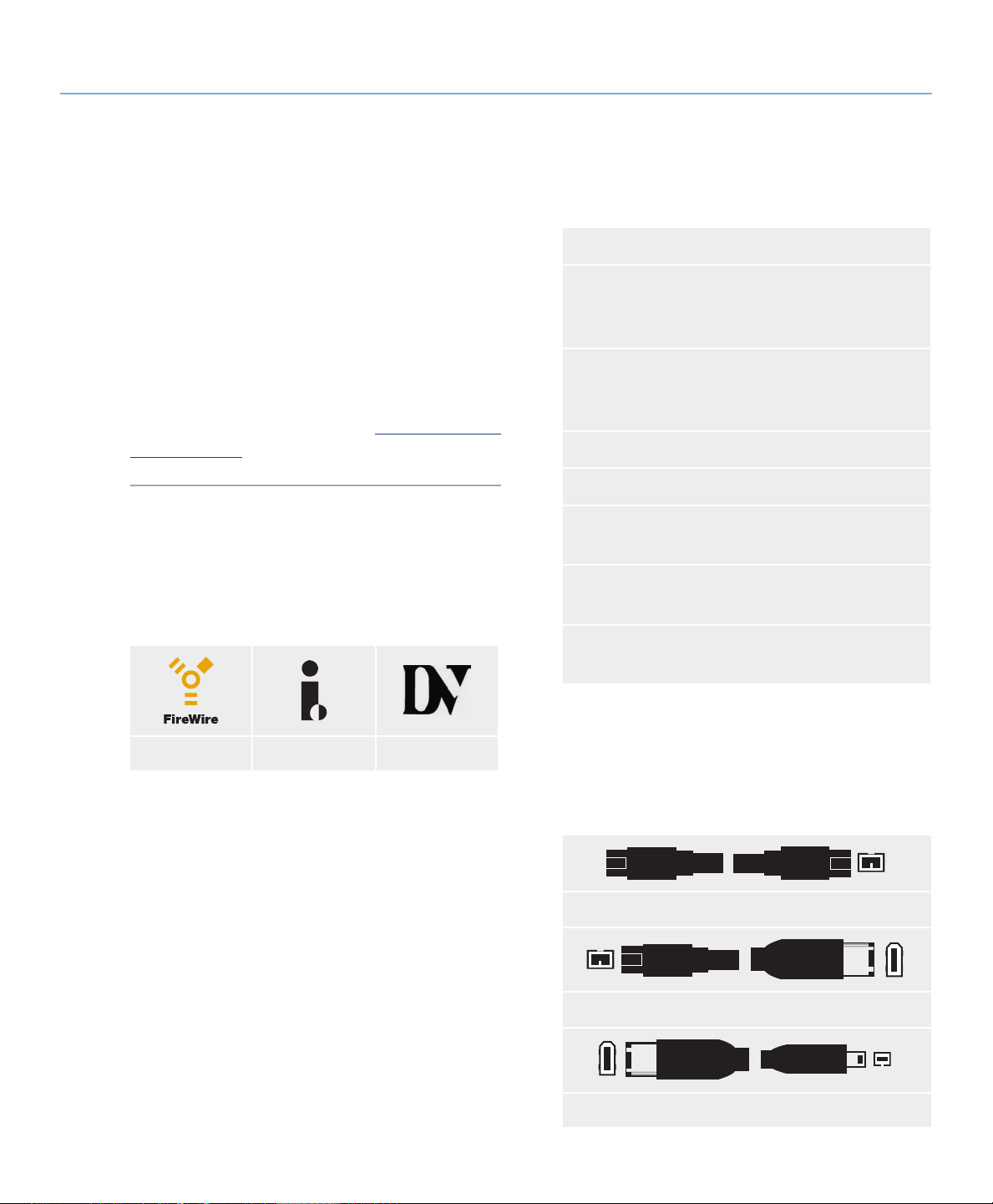
FireWire Icons
eses icons will help you easily identify the FireWire
interface. ey appear on FireWire cables, and next to
the FireWire port connectors on certain computers.
FireWire 800 Benefits
Resourceful architecture: FireWire 800 reduces
❖
delays in arbitration and signal distortion, and
increases throughput.
Backwards compatibility: adapter cables al-
❖
low FireWire 400 devices to operate under the
FireWire 800 port (at FireWire 400 speed).
FireWire 400 & FireWire 800 Benefits
Hot-pluggable: devices can be added and re-
❖
moved while the bus is active.
Isochronous data delivery: no dropped frames
❖
– FireWire supports real-time data delivery.
Flexible: up to 63 devices can be connected on a
❖
single bus.
FireWire icon iLink icon DV icon
FireWire Cables
ere are two categories of FireWire cables on the
market: FireWire 800 cables, which feature the 9-to-9pin, 9-to-6-pin, and 9-to-4-pin cables; and the original
FireWire cables which feature the 6-to-6-pin and 6-to4-pin cables.
FireWire 800 9-to-9 Pin Cable and Cable End
FireWire 800 9-to-6 Pin Cable and Cable End
iLink/DV Cable and Cable End (Sold Separately)
Page 14
LaCie Biggest Quadra
User Manual
2.5.2. Hi-Speed USB 2.0 Cables and Connectors■
About the LaCie Biggest Quadra
page 13
USB is a serial input/output technology for connecting peripheral devices to a computer or to each other.
Hi-Speed USB 2.0 is the latest implementation of this
standard, and it provides the necessary bandwidth and
data transfer rates to support high speed devices such as
hard drives, CD/DVD drives and digital cameras.
Please see section 9. USB Questions & Answers for
more information on USB’s uses and capabilities.
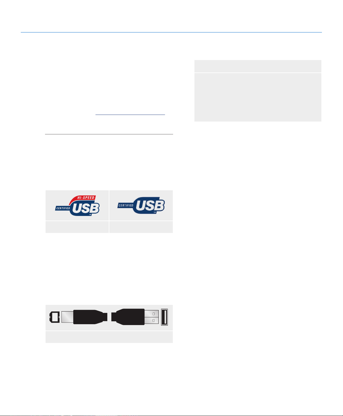
USB Icons
ese icons will help you easily identify the USB
interfaces. ey appear on USB cables and next to the
USB port connectors on certain computers.
USB 2.0 icon USB 1.1 icon
Hi-Speed USB 2.0 Benefits
Backwards compatibility: Hi-Speed USB 2.0
❖
works with the original USB specifications.
Hot-swappable: no need to shut down or restart
❖
your computer when adding or removing devices.
USB 2.0 Cables
Your LaCie drive is shipped with a Hi-Speed USB
2.0 cable, to ensure maximum data transfer performance
when connected to a Hi-Speed USB 2.0 port. e cable
will also work when connected to a USB port, but drive
performance will be limited to USB 1.1 transfer rates.
USB 2.0 Cable Ends
Page 15
LaCie Biggest Quadra
S-ATA
S-ATA
User Manual
2.5.3. eSATA Cables and Connectors■
Your LaCie Biggest Quadra uses the latest in SATA
technology, allowing interface (or bus) transfer rates of
up to 3 Gbits/s. SATA technology was originally developed to serve as an internal interface, delivering improved performance to internal connections. Soon after,
eSATA, or external SATA was developed, allowing for
the use of shielded cables outside the PC.
eSATA technology was developed to be rugged and
durable. eSATA connectors do not have the “L” shaped
design of other SATA connectors. In addition, the guide
features are vertically offset and reduced in size to prevent the use of unshielded internal cables in external applications.
About the LaCie Biggest Quadra
page 14
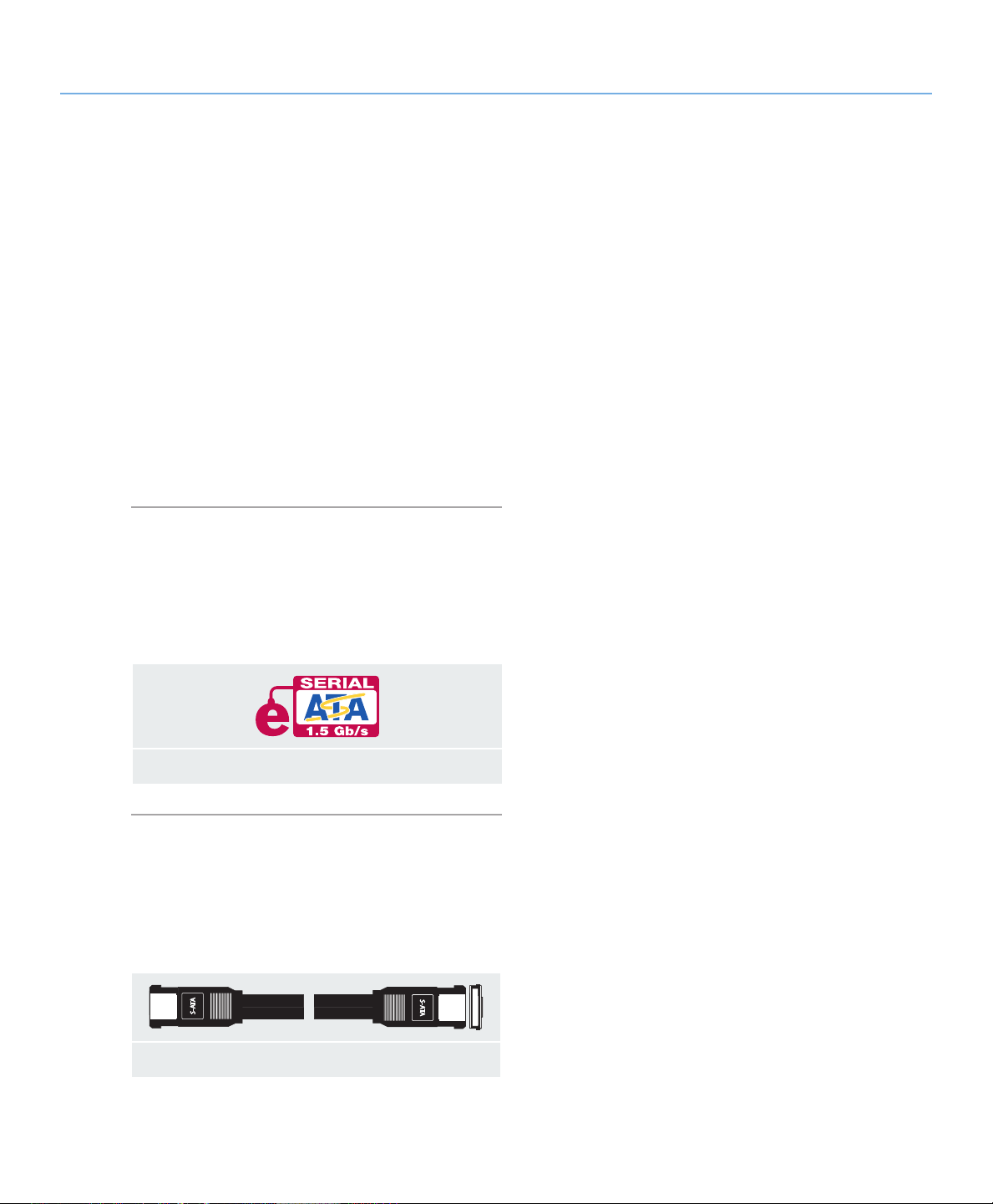
eSATA Icons
is icon will help you easily identify the eSATA
interfaces. ey appear on eSATA cables and next to the
eSATA port connectors on certain computers.
eSATA 1.5 Gbits/s icon
eSATA Cables
Your LaCie drive is shipped with a eSATA cable, to
ensure maximum data transfer performance when connected to a eSATA port.
eSATA Cable and Cable End
Page 16
LaCie Biggest Quadra
User Manual
2.6. Drive Tray Locks
About the LaCie Biggest Quadra
page 15
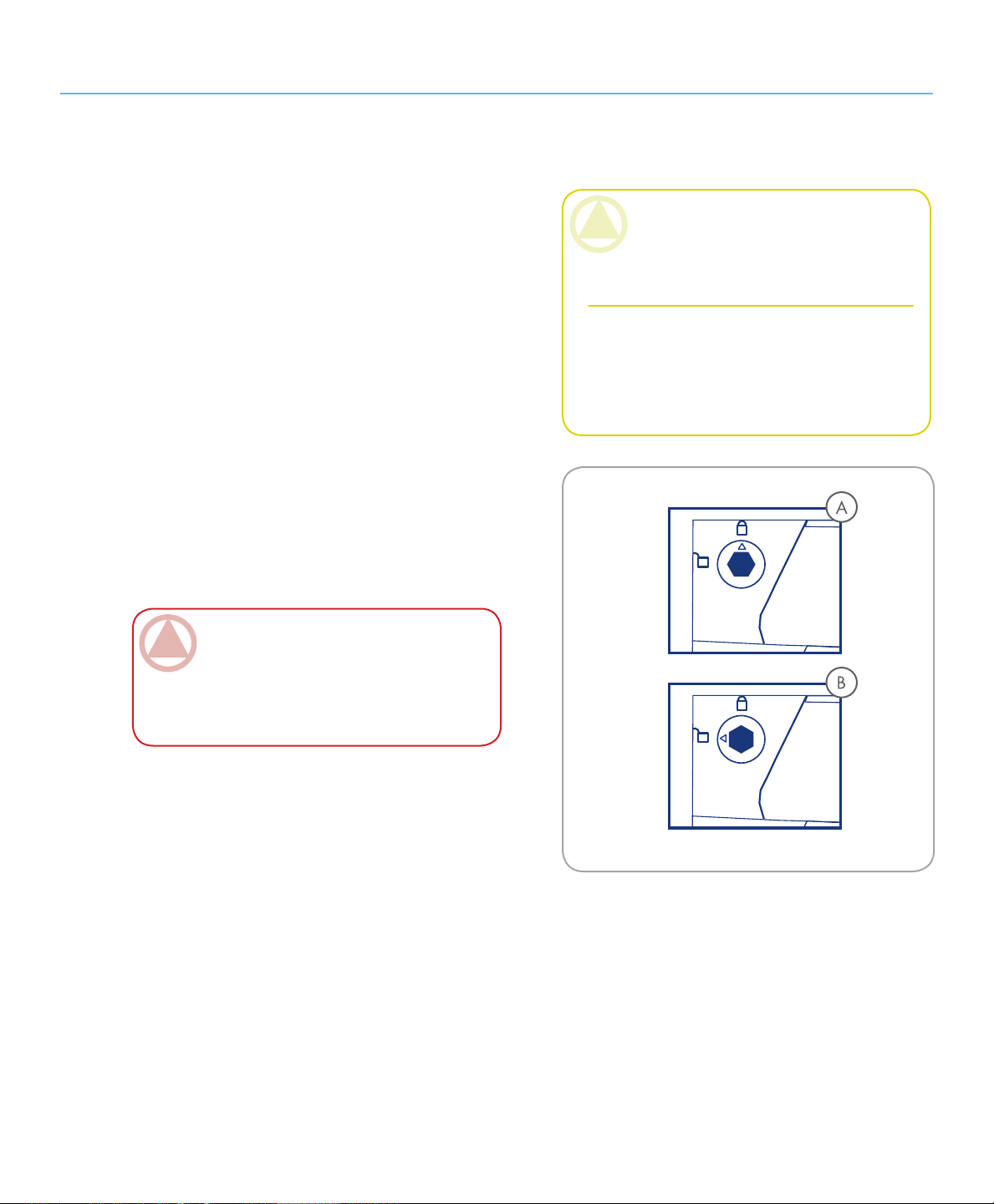
e Biggest Quadra’s drive trays can be locked into
place with the provided keys to prevent accidental drive
tray removal and damage. LaCie recommends that you
keep your drive trays locked while the Biggest Quadra
is in use.
To lock a drive tray:
Ensure that the drive tray is fully seated in its bay.
1.
Insert the key into the lock.
2.
Turn the key to the right until the arrow on the lock
3.
aligns with the “locked” symbol (A). See Fig. 2.6.
To unlock a drive tray:
Insert the key into the lock.
1.
Turn the key to the let until the arrow on the lock
2.
aligns with the “unlocked” symbol (B). See Fig. 2.6.
ImpOrTANT INfO: e drive tray keys are
exactly the same size as 5mm hex key wrenches.
If you can not find the keys provided with your
Biggest Quadra, you can also use 5mm hex key
wrenches to unlock the drive trays.
CAUTION: To prevent the unexpected or acci-
dental pull-out of drive trays, LaCie recommends
that you keep drive trays locked while the Biggest
Quadra is in use.
Always unlock drive trays before attempting to
remove them from or install them in the system
tower. Failure to do so may damage the drives
and void the warranty.
Fig. 2.6.
Page 17
LaCie Biggest Quadra
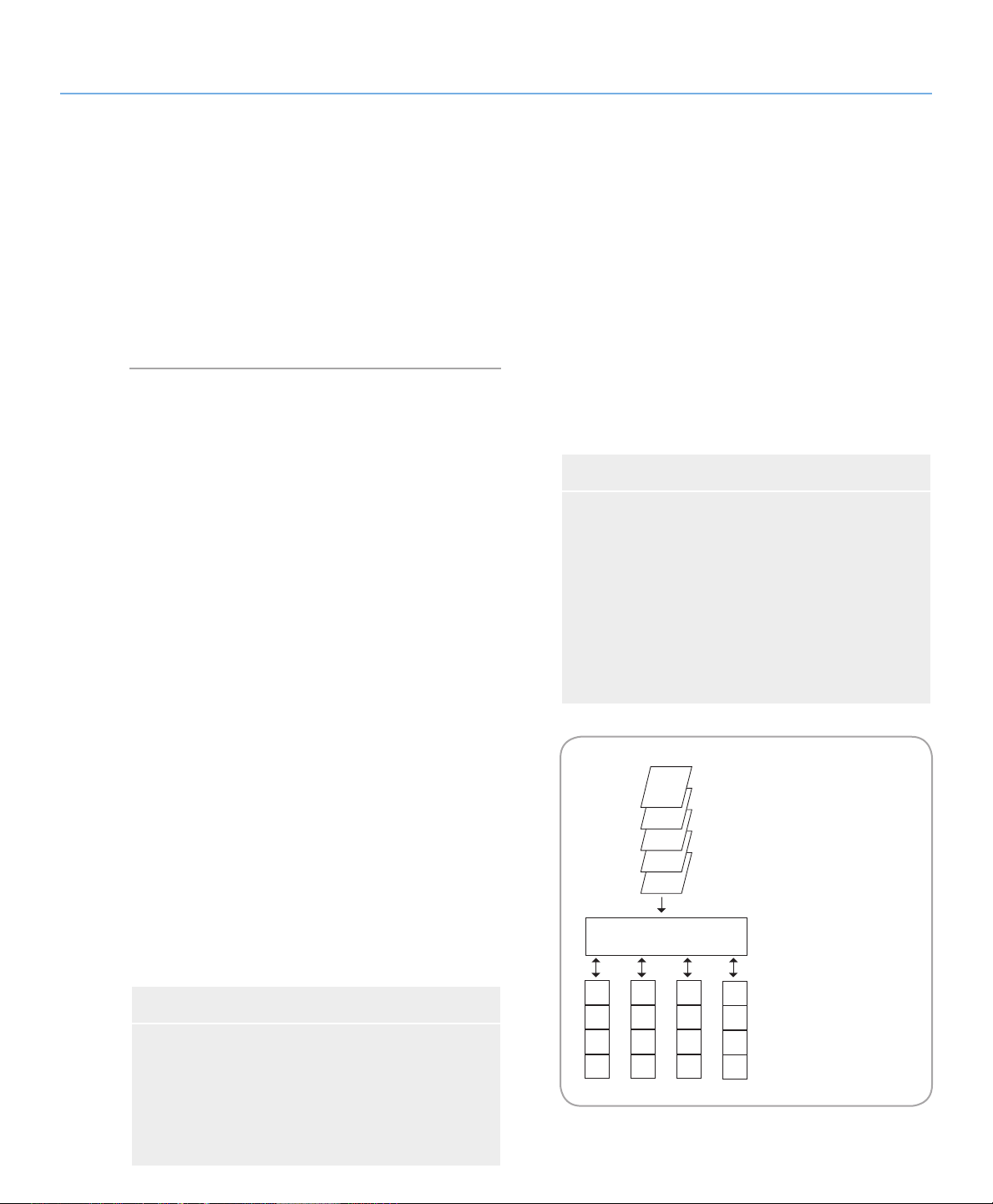
This diagram represents a
RAID 0 array, consisting of
four disks, which are
connected to the Controller.
Data blocks are distributed
across all of the disks in the
array.
A
E
I
M
B
F
J
N
C
G
K
O
D
H
L
Etc...
E
D
C
B
A
CONTROLLER
User Manual
3. Understanding RAID
Your LaCie Biggest Quadra is shipped with a preconfigured RAID level of 5, but it supports four different RAID levels: 0, 0 + 1, 5 and 5 + Hot Spare. is
section will help you decide which RAID level is right
for you.
3.1. RAID 0
Understanding RAID
page 16
Striped Disk Array Without Fault Tolerance
Characteristics and Advantages■
Also called striping, this level offers high transfer
Data is broken down into blocks and each block
rates and is ideal for large blocks of data where speed
is of the utmost importance. RAID 0 implements a
striped disk array, where all of the hard disks are linked
together to form one large aggregate hard disk. In this
configuration, data is broken down into blocks and each
block is written to a separate disk drive within the array;
I/O performance is greatly improved by spreading the I/
O load across several drives. In this array, however, when
one disk fails, all of the data on the array is lost.
Storage capacity is determined by the smallest disk
in the array, and the smallest disk’s capacity is applied to
all of the other disks in the array. So, for instance, if you
had four disks installed, ranging in capacity from 40GB
to 80GB, when the RAID 0 array is built your system
will see one, 160GB (40GB x 4) hard disk.
While this is a very simple and easily implemented
design, RAID 0 should never be used in mission critical environments. When even just one disk in the array
fails, all of the data on the entire array will be lost.
Recommended Uses■
❖
is written to a separate disk drive
I/O performance improved by spreading the load
❖
across multiple drives
Overhead is lowered due to no calculations for
❖
parity
Simple design and easily implemented
❖
Fig. 3.1.
Video production and editing
❖
Image editing
❖
Pre-press applications
❖
Applications requiring high-bandwidth
❖
Page 18
LaCie Biggest Quadra
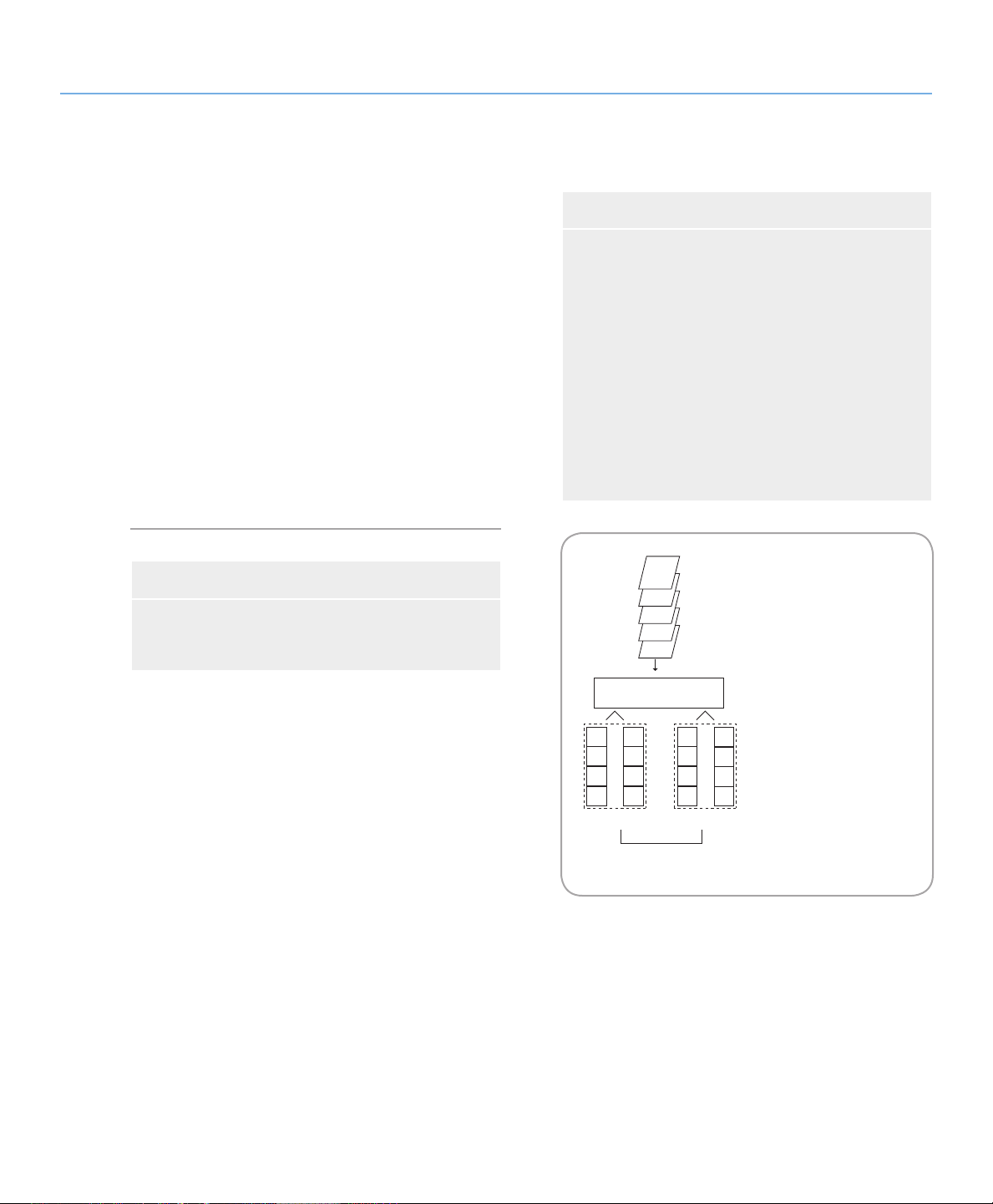
This diagram represents a
RAID 0 +1 array, consisting of
four disks, which are
connected to the Controller.
The Controller creates two
matching RAID 0 arrays on
the four disks.
E
D
C
B
A
CONTROLLER
A
C
E
G
B
D
F
H
R0 R0
A
C
E
G
B
D
F
H
R1
User Manual
3.2. RAID 0 + 1
Understanding RAID
page 17
High Data Transfer Performance
is level combines striping and mirroring, which
provides full data redundancy and protects data in the
event that multiple drives fail (provided that the data on
one of each mirrored pair of drives is intact).
Storage capacity in this configuration is determined
by multiplying the capacity of the smallest disk by two.
If, for instance, there were four drives installed that
ranged in capacity from 40GB to 70GB, as a RAID 0+1
array, the total available capacity would be 80GB (40GB
x 2). In this configuration, you must have an even number of disks, so in the case of the LaCie Biggest Quadra,
you would need to have four hard disks installed.
Recommended Uses■
Imaging Applications
❖
General Fileserver
❖
Characteristics and Advantages■
Implemented as a mirrored array with RAID 0
❖
arrays as the segments
e same fault tolerance as RAID level 5
❖
Fault-tolerance overhead is the same as that of
❖
mirroring
High I/O rates are achieved thanks to multiple
❖
striped segments
Excellent design for those seeking high perfor-
❖
mance, without achieving maximum reliability
Fig. 3.2.
Page 19

LaCie Biggest Quadra
This diagram represents a
RAID 5 array, consisting of
four disks, which are
connected to the Controller.
Parity blocks are represented
by the letter P.
A
D
PJKL
G
B
E
J
C
H
K
F
I
E
D
C
B
A
CONTROLLER
PABC
L
PGHI
PDEF
User Manual
3.3. RAID 5
Understanding RAID
page 18
Independent Data Disks With Distributed Parity Blocks
is is the most versatile RAID level and offers high
I/O transaction rates, which greatly helps applications
that perform large numbers of concurrent requests. If
one drive in a RAID 5 array fails, the lost data can be
rebuilt from data on the remaining, functional disks.
Essentially, RAID level 5 is a striped set with parity,
and requires at least three disks to implement. In this
configuration, data is saved across several hard disks, as
in a RAID 0 array, but parity information is also saved
across the disks. It is this parity information which provides the fault-tolerance protection; if one hard disk in
the set fails, the data that it contains can be rebuilt by
utilizing the parity information from the other hard
disks. With the parity data being stored across the array, this also serves to maximize the amount of storage
capacity available amongst the disks in the array while
still providing data redundancy.
Storage capacity in a RAID level 5 configuration is
the result of a mathematical expression that compares
data from the drives and a calculates another piece of
data called parity. In this situation, then, storage capacity
is calculated by multiplying the number of disks in the
array, minus one, by the capacity of the smallest disk in
the array. So, for instance, if a RAID 5 array is created
with four drives of varying capacities of 40GB, 50GB,
60GB and 70GB, the total capacity of the array would
be 120GB [3 (4 disks – 1 disk) x 40 = 120].
Characteristics and Advantages■
Highest Read data transaction rate
❖
Medium Write data transaction rate
❖
High efficiency through a low ratio of ECC (Par-
❖
ity) disks to data
Good aggregate transfer rate
❖
Fig. 3.3.
Recommended Uses■
File and Application Servers
❖
Database Servers
❖
Web, E-mail and News Servers
❖
Intranet Servers
❖
Page 20

LaCie Biggest Quadra
This diagram represents a
RAID 5 array, consisting of
four disks, which are
connected to the Controller.
Parity blocks are represented
by the letter P.
E
D
C
B
A
CONTROLLER
A
C
PEF
G
B
H
PCD
E
F
PAB
PGH
D
" /
-* ,
User Manual
3.4. RAID 5 + Hot Spare
is level is the same as RAID 5, but one disk is designated as a “Hot Spare,” which means that in the event of
a disk failure, the “Hot Spare” disk would automatically be
activated to replace the failed disk.
e storage capacity of a RAID 5+ Hot Spare array follows the same logic as that of RAID 5, but with the difference being that there is one less disk in the array. So, for
instance, if there was a RAID 5+ Hot Spare array with three
drives of varying capacities of 40GB, 50GB and 60GB, and
one disk designated as the hot spare with a capacity of 70GB,
the total capacity of the array would be 80GB [2 (3 disks – 1
disk) x 40 = 80].
Understanding RAID
page 19
Fig. 3.4.
Page 21

LaCie Biggest Quadra
User Manual
4. Setting Up Your LaCie Biggest Quadra
is chapter covers the installation and configuration of your LaCie Biggest Quadra. A relatively easy
process, you will be guided through the five following
steps:
Setting Up the Biggest Quadra
page 20
Step 1 4.1. Setting e RAID Level – e LaCie Biggest Quadra is pre-configured at RAID level
5, but you have the option of customizing your RAID level in this step.
Step 2 4.2. Creating An Array – e LaCie Biggest Quadra will automatically initialize the four
hard disks in the unit.
Step 3 4.3. Connecting to a Host Computer – e LaCie Biggest Quadra can be connected to a
host computer through the FireWire 800, Hi-Speed USB 2.0 or eSATA interface. is section covers all three connectivity methods.
Step 4 4.4. Setting e Date & Time – Configure your LaCie Biggest Quadra for your local use. Page 29
Step 5 4.5. Formatting and Partitioning Your LaCie Hard Drive – is section is divided between
the two different operating systems, Mac OS and Windows, and details the process for formatting and partitioning the LaCie Biggest Quadra.
Page 21
Page 24
Page 26
Page 30
Page 22

LaCie Biggest Quadra
User Manual
4.1. Setting the RAID Level
Setting Up the Biggest Quadra
page 21
e LaCie Biggest Quadra is pre-configured at RAID
level 5, but it may be re-configured. e RAID level is set
using the RAID Level Switch Selectors on the rear panel of
the LaCie Biggest Quadra. e RAID level selectors consist
of two switches, with four possible switch position combinations: RAID 0, 0 + 1, 5 and 5 + Hot Spare.
CAUTION: e LaCie Biggest Quadra must
be powered off to change the RAID level.
CAUTION: If there is data on the array, chang-
ing the RAID level may lead to the loss of all of
the data on the array.
ImpOrTANT INfO: In the event that the
RAID level does not correspond to both the disk
settings and the RAID Level Switch Selectors, the
LCD will display the following two alternating
messages:
1. “RAID level”
“Unmatched”
2. “Current: Rx” (i.e. the current RAID level settings of the installed disks)
“Original: Rx” (i.e. the RAID level settings on
the RAID Level Switch Selectors)
Example:
e RAID Level Switch Selectors are positioned to indicate a RAID 0 setting, but the
disks were set earlier as a RAID 5 array, the
LCD will display the following two alternating
messages:
1. “RAID Level”
“Unmatched”
2. “Current: R5”
“Original: R0”
In this situation, the array will not function.
ere are two options:
1. Shut down the LaCie Biggest Quadra and
re-position the RAID Level Switch Selectors
to the previous RAID setting, in this case,
RAID 5.
2. Re-insert the four drives, and re-create the
array as a RAID 0 array. If there is any data on
the disks, it will be lost during the initialization.
Page 23

LaCie Biggest Quadra
User Manual
4.1.1. RAID 5■
is is the default setting of the LaCie Biggest
Quadra. Follow these steps to set the RAID level at
RAID 5.
Power off the LaCie Biggest Quadra.
1.
Move switch 1 and 2 of the RAID Level Switch Se-
2.
lectors to the OFF position.
CAUTION: In a RAID 5 array, in the event
that a disk needs to be replaced, always replace the
failed disk with the LaCie Biggest Quadra’s power
on. Do not turn the LaCie Biggest Quadra’s power
off; doing so may lead to the loss of the data on
the array.
Setting Up the Biggest Quadra
page 22
Fig. 4.1.1
4.1.2. RAID 5 + Hot Spare■
Power off the LaCie Biggest Quadra.
1.
Move switch 1 of the RAID Level Switch Selectors
2.
to the OFF position. Move switch 2 of the RAID
Level Switch Selectors to the ON position.
ImpOrTANT INfO: In a RAID 5 + Hot
Spare array, the disk in the top drive bay is desig-
nated as the Hot Spare (the default setting), and
the Disk Status Indicator will light in amber to
indicate this configuration.
Fig. 4.1.2
TeChNICAl NOTe: In the initial configura-
tion of a RAID 5 + Hot Spare array, the top drive
bay (Drive Bay 1) is the default Hot Spare (the Disk
Status Indicator will be amber). In the event that a
disk fails, the Hot Spare position will change.
For example, if the disk in Drive Bay 3 fails, then
the Hot Spare disk in Drive Bay 1 will be re-built
and will no longer be the Hot Spare. Instead,
when you place a new disk in Drive Bay 3, it will
become the new Hot Spare, and will be indicated
by the amber Disk Status Indicator.
Page 24

LaCie Biggest Quadra
User Manual
4.1.3. RAID 0■
Power off the LaCie Biggest Quadra.
1.
Move switch 1 and 2 of the RAID Level Switch Se-
2.
lectors to the ON position.
4.1.4. RAID 0 + 1■
Power off the LaCie Biggest Quadra.
1.
Move switch 1 of the RAID Level Switch Selectors
2.
to the ON position. Move switch 2 of the RAID
Level Switch Selectors to the OFF position.
Setting Up the Biggest Quadra
page 23
Fig. 4.1.3
Fig. 4.1.4
TeChNICAl NOTe: In a RAID 0+1 array, the
disks in Drive Bays 1 and 2 are one independent
RAID 1 group, while the disks in Drive Bays 3 and
4 represent another independent RAID 1 group.
is allows one disk from each separate RAID 1
group to fail simultaneously.
Page 25

LaCie Biggest Quadra
USB
eSATA
0 5 0-1 5-S
User Manual
4.2. Creating an Array
4.2.1. Initializing the Disks■
To initialize the disks in your array:
Make sure the Biggest Quadra is turned off and the
1.
power cable is not connected.
Ensure that the RAID level is correctly set and
2.
configured. Refer to section 4.1. Setting the RAID
Level.
Ensure that each of the individual drive trays is not
3.
locked and then pull each drive tray handle to release
the latch. Slide each of the drive trays out from the
LaCie Biggest Quadra slightly (Fig. 4.2.A).
Connect the power cable to the LaCie Biggest
4.
Quadra and a grounded electrical outlet. See A inFig. 4.2.B.
Setting Up the Biggest Quadra
page 24
Fig. 4.2.A
Turn on the LaCie Biggest Quadra by moving the
5.
power switch to the “on” position. See B in Fig.
4.2.B.
Slide each of the drive trays back into the LaCie Big-
6.
gest Quadra, and push the drive tray handles flat to
lock the drive trays into place (Fig. 4.2.C).
Once all of the drive trays have been closed and
locked, the LaCie Biggest Quadra will check the status
of the four installed disks. If all four of the disks have
not been initialized before (which will be the case for
the first connection of the LaCie Biggest Quadra), the
RAID level initialization will begin automatically.
(continued on next page)■
on
off
Fig. 4.2.B
Fig. 4.2.C
Page 26

LaCie Biggest Quadra
User Manual
Setting Up the Biggest Quadra
page 25
If you are resetting the RAID level after having used
the LaCie Biggest Quadra at another RAID level, the
LaCie Biggest Quadra will display a warning on the
LCD, asking if you are certain that you want to initialize the new RAID array. e initialization process will
erase any data on the disks.
e LCD Display of the LaCie Biggest Quadra will
issue a “Create New RAID” message. Press the Enter
button to select Yes, or press the Menu button to select
No.
ImpOrTANT INfO: e initialization pro-
cess is a time-intensive process and is dependent
upon the size of the disks and the RAID level being initialized. For example, four, 400GB disks in a
RAID 5 array could take over two hours.
In the event that the power is interrupted during
the initialization process, the LaCie Biggest
Quadra will resume the initialization process
from the point of interruption as soon as the
power is restored.
All four of the Drive Bays should be locked in
place in the LaCie Biggest Quadra before the
initialization process. If the four Drive Bays are
not installed correctly when the power is turned
on, the alarm will sound and a “RAID Fail”
message will be displayed on the LCD, unless: a
RAID 5 + Hot Spare level has been set and the
bottom three Drive Bays have disks installed.
In this instance, the initialization of a RAID 5
array will begin.
TeChNICAl NOTes: For a complete list of
the LCD Display messages and Disk Status and
Activity Indicators, please see sections 5.1. Disk
Status and Activity Indicators and 5.2. LCD Display Messages.
e RAID capacity is determined by the RAID
level and the capacity of the drives installed. For
more information, please see sections 3.1, RAID
0, 3.2., RAID 0 + 1, 3.3., RAID 5 and 3.4.,
RAID 5 + Hot Spare.
At the time of publication (September 2006),
some Windows versions do not allow the configuration of storage policies with more than 2TB.
is limitation does not exist for Mac OS X.
Page 27

LaCie Biggest Quadra
User Manual
4.2.2. Managing Volumes over 2TB in Windows■
ImpOrTANT INfO: e Lacie Biggest Quadra supports over 2TB capacity on all operating systems except
Windows 2000 and Windows XP which are limited to 2TB. In Windows 2000 and Windows XP, the maximum
capacity which will mount, regardless of the RAID mode selected, is 2TB.
If you have created an array of more than 2TB on
Windows 2000 or Windows XP, please use the follow-
ing steps to make the array visible in Windows Disk
Manager:
With the scroll button, select Enable over 2TB on
1.
the LCD panel. Press ENT to continue.
Select NO to disable the function. e array will be
2.
visible in Disk Manager, but is limited to 2TB on
Windows 2000 and Windows XP.
Setting Up the Biggest Quadra
page 26
TeChNICAl NOTe: If you switch from Win-
dows 2000 or Windows XP to another operating
system (Windows Server 2003, Windows Vista or
Mac OS X), activate the “Enable over 2TB” function by selecting YES in step 2, above to allow access to arrays over 2TB.
In Windows Server 2003 and Windows Vista, a
RAID array with more than 2TB accessible space will
mount as two volumes. To make the volumes appear as
one volume:
Right-click the My Computer icon on your desk-
1.
top and select Manage from the right-click options
menu.
Select Disk Management under Storage to open the
2.
Windows Disk Manager.
Right-click the concerned disks and select Convert
3.
to GPT Disk (Fig. 4.2.2.A). e two volumes appear
as one (Fig. 4.2.2.B).
Two volumes
Fig. 4.2.2.A
One volume
Fig. 4.2.2.B
Page 28

LaCie Biggest Quadra
User Manual
4.3. Connecting to a Host Computer
Setting Up the Biggest Quadra
page 27
Once the LaCie Biggest Quadra has finished the
initialization of the array, you will be ready to connect
the LaCie Biggest Quadra to a host computer. is section is divided into the three different interface connectivity methods: USB, FireWire and eSATA.
Although the Biggest Quadra only has three types
of interface port (USB 2.0, FireWire 800 and eSATA),
it can be connected to a fourth type of host interface
port, FireWire 400, with the FireWire 800/400 9-to-6
pin interface cable. See section 4.3.1, Connecting to the
Host Computer via FireWire.
ImpOrTANT INfO: e initialization must
be completed before connecting the interface cable. Otherwise, the LaCie Biggest Quadra will not
be recognized by the host computer.
ImpOrTANT INfO: e two interfaces,
FireWire and USB, cannot be used at the same
time. You must connect the Biggest Quadra to the
host computer using one interface or the other.
Page 29

LaCie Biggest Quadra
USB
eSATA
0 5 0-1 5-S
USB
eSATA
0 5 0-1 5-S
User Manual
4.3.1. Connecting to the Host Computer via FireWire■
1.
Follow the steps in sections 4.1. Setting e RAID
Level and 4.2. Creating an Array to establish a RAID
array.
2.
Connect the 9-pin end (A) of the FireWire 800 cable
into the FireWire 800 port on the back of the LaCie
Biggest Quadra (Fig. 4.3.1.A/B).
Connect either the other end of the 9-pin FireWire
3.
800 cable (B) into an available FireWire 800 port on
your computer (Fig. 4.3.1.A), or connect the 6-pin
end of the FireWire 800/400 cable into an available
FireWire 400 port on your computer (Fig. 4.3.1.B).
It will take a few seconds for your computer to recognize the drive and for it to appear on the desktop or
in My Computer.
Setting Up the Biggest Quadra
page 28
ImpOrTANT INfO: e LaCie Biggest
Quadra ships with both a FireWire 800 9-to-9pin cable and a FireWire 800/400 9-to-6-pin
cable. e FireWire 800 9-to-9-pin cable is used
when the host computer has a FireWire 800 port.
e FireWire 800/400 9-to-6-pin cable is used
when the host computer only has a FireWire 400
port. For more information about FireWire, please
see sections 2.5.1. FireWire 800 Cables and Con-
nectors, 7.3. Optimizing Data Transfers and 8.
FireWire Questions & Answers.
Your LaCie Biggest Quadra will now need to be formatted. Go to section 4.5. Formatting and Partitioning
Your LaCie Hard Drive, for more information.
Fig. 4.3.1.A
A
Fig. 4.3.1.B
A
B
B
Page 30

LaCie Biggest Quadra
USB
eSATA
0 5 0-1 5-S
User Manual
4.3.2. Connecting to the Host Computer via Hi-Speed USB 2.0■
1.
Follow the steps in sections 4.1. Setting e RAID
Level and 4.2. Creating an Array to establish a RAID
array.
2.
Connect the Hi-Speed USB 2.0 cable into the HiSpeed USB 2.0 port on the back of the LaCie Biggest Quadra (A).
Connect the other end of the Hi-Speed USB 2.0
3.
cable into an available USB port* on your computer
(B).
It will take a few seconds for your computer to recognize the drive and for it to appear on the desktop or
in My Computer.
Your LaCie Biggest Quadra will now need to be formatted. Go to section 4.5. Formatting and Partitioning
Your LaCie Hard Drive, for more information.
Setting Up the Biggest Quadra
page 29
TeChNICAl NOTe: * To achieve Hi-Speed
USB 2.0 transfer rates, you have to be connected
to a Hi-Speed USB 2.0 port on your computer.
Otherwise, you will be limited to USB 1.1 data
transfer rates. For more information about USB,
please see secions 2.5. Cables and Connectors, 7.3.
Optimizing Data Transfers, and 9. USB Questions
& Answers.
TeChNICAl NOTe: Windows Users! After
the first connection of a USB-based peripheral,
Windows detects the drive, and will install it automatically as a new peripheral, even if you have
previously installed it on another port on the same
USB bus. Let Windows install the USB drivers of
your LaCie drive.
Fig. 4.3.2.
A
B
Page 31

LaCie Biggest Quadra
USB
eSATA
0 5 0-1 5-S
User Manual
4.3.3. Connecting to the Host Computer via eSATA■
1.
Follow the steps in sections 4.1. Setting e RAID
Level and 4.2. Creating an Array to establish a RAID
array.
2.
Connect the eSATA cable to the eSATA port on the
back of the LaCie Biggest Quadra (A).
Connect the other end of the eSATA cable to an
3.
available eSATA port on your computer (B).
It will take a few seconds for your computer to recognize the drive and for it to appear on the desktop or
in My Computer.
Your LaCie Biggest Quadra will now need to be formatted. Go to section 4.5. Formatting and Partitioning
Your LaCie Hard Drive, for more information.
Setting Up the Biggest Quadra
page 30
Fig. 4.3.2.
B
A
Page 32

LaCie Biggest Quadra
User Manual
4.4. Setting the LCD Display Time & Date
To change the time and date on the LCD Display,
press and hold the Enter/Mute button (A) for five seconds. Release the button to display the date and time
settings screen.
To adjust the time and date values, use the Scroll
button (B) on the left-side of the LCD Display to
change the values (Fig. 4.4.A).
Press the Enter button to confirm your selection and
move to the next value.
Start by adjusting the year (YY), then move to the
month (MM), the day (DD), and finally the hour (HH)
and minute (MM) (the time is measured in the 24-hour
clock format).
Pressing the Enter button on the final selection will
set the time and date.
Setting Up the Biggest Quadra
page 31
YY/MM/DD HH:MM
05/12/06 15:37
Fig. 4.4
Page 33

LaCie Biggest Quadra
User Manual
4.5. Formatting and Partitioning
Setting Up the Biggest Quadra
page 32
Before the LaCie Biggest Quadra array can be fully
utilized, it needs to be formatted. During this process,
the array can also be customized with partitions.
Formatting a disk consists of the following: the operating system erases all of the bookkeeping information on the disk, tests the disk to make sure that all of
the sectors are reliable, marks bad sectors (i.e., those that
are scratched) and creates internal address tables that it
4.5.1. Windows Users■
ImpOrTANT INfO: Before beginning the
format and partition process, ensure that there are
no warning or error i messages being displayed on
the LCD Display of the LaCie Biggest Quadra.
After having followed the steps to set the RAID
level, create the array and connect the interface cable,
the LaCie Biggest Quadra must now be formatted and
partitioned before it can be used.
later uses to locate information. As you format the drive,
you will have the opportunity to divide the hard drive
into sections, called partitions. A partition is a section of
the hard drive’s storage capacity that is created to contain files and data.
Once formatted, the actual available storage capacity
varies, depending on operating environment, and is generally about 10% less than the non-formatted capacity.
Right click My Computer and click Manage.
1.
From the Computer Management window, select
2.
Disk Management (located below the Storage
group). See Fig. 4.5.1.A.
If the Initialize and Convert Disk Wizard window
3.
appears, click Cancel.
Windows will list the hard drives that are installed
4.
on the system. Locate the drive that is represented
by the icon. Right click the icon and select
Initialize.
In the box to the right that says Unallocated, right
5.
click and select New Partition...
In the first page of the New Partition Wizard, click
6.
Next. See Fig. 4.5.1.B.
Fig. 4.5.1.A
Fig. 4.5.1.B
Page 34

LaCie Biggest Quadra
User Manual
8. Click Next.
9. Click Next.
10. Click Next.
11. Click Next.
12. In this window (Fig. 4.5.1.C), you have the option
of selecting the Quick Format option. is allows a
much faster format; however, this will disallow Disk
Management to check the drive for errors (recommended). Click Next.
TeChNICAl NOTe: For a more detailed dis-
cussion on the various file system formats and partitioning, please refer to section 7.1. File System
Formats.
Setting Up the Biggest Quadra
page 33
Fig. 4.5.1.C
13. Click Finish to begin the format process.
14. Your drive is ready for use and should now appear in
your My Computer.
Fig. 4.5.1.D
Page 35

LaCie Biggest Quadra
User Manual
4.5.2. Mac Users■
ImpOrTANT INfO: Before beginning the
format and partition process, ensure that there are
no warning or error i messages being displayed on
the LCD Display of the LaCie Biggest Quadra.
1. If it is not already on, power on the host computer.
2. As soon as the array is detected by your computer, it
will mount to the desktop as an untitled device.
3. From Finder, use the Go menu and open the Utilities
folder. Double-click on the Disk Utility program.
4. e Disk Utility dialog box will appear (Fig. 4.5.2.A).
Your LaCie Biggest Quadra array will appear on
the left-hand side, in the list of hard disks that are
mounted on your system. You should see a volume
that represents your internal hard drive, and one that
reads LaCie.
Setting Up the Biggest Quadra
page 34
Fig. 4.5.2.
5. Select the LaCie drive, and then click on the Parti-
tion tab.
6. From the Volume Scheme: button, choose the number of partitions you want to divide the drive into by
clicking on the pull down menu starting with Cur-
rent (Mac OS 10.x gives you the option of dividing
the drive into at most 8 partitions). You can customize the size of the partitions by using the slide bar
between the partitions in the Volume Scheme: area.
7. In the Volume Information section, create a name
for each partition, choose the volume format (Mac
OS Extended, Mac OS Standard, MS-DOS File
System or UNIX File System) and the volume size.
8. Once you have finalized the volume format, number
of partitions, size and options, click OK. e following message will appear: “Warning! Saving the new
volume will erase all existing volumes. is can NOT
be undone. Are you sure you want to do that?” Click
Partition to continue.
9. Mac OS 10.x will automatically setup the disk with
the partitions and volume format you selected, and
your new drive will be available for use.
TeChNICAl NOTe: Under Mac OS 10.3.x,
the default format setting is Mac OS Extended
( Journaled). Journaling provides a continuous
record of changes to files on the hard drive. You
will not be able to format in the MS-DOS File
System, either, unless you choose the Erase tab in
the Disc Utility window and create an entire MSDOS File System volume. For more information,
please refer to section 7.1. File System Formats.
ImpOrTANT INfO: Please refer to section
7.1. File System Formats, for a more detailed com-
parison of the various file system formats.
ImpOrTANT INfO: Apple recommends that
unless you have a specific reason to use the UNIX
File System (UFS), you should use the Mac OS
Extended format since it provides a more familiar
experience to Macintosh users.
Page 36

LaCie Biggest Quadra
User Manual
5. Using the LaCie Biggest Quadra
5.1. Disk Status and Activity Indicators
is list is a key to the messages of the Disk Status
Indicator and Disk Activity Indicator on each of the individual Drive Bays.
Disk Status Indicator Disk Activity Indicator Controller Status
Alternating green & amber Flashing blue RAID being initialized
Alternating green & amber Flashing blue RAID being rebuilt
Solid green Unlit RAID initialization complete
Using the Biggest Quadra
page 35
Solid green Unlit RAID established/no activity
Solid green Flashing blue Data being accessed
Solid red Unlit Disk failure/disk not properly installed
Solid amber Unlit Hot Spare disk in RAID 5 + Hot Spare mode
If the Disk Status Indicator is being displayed as a
solid red light, ensure that the appropriate drive is not:
Locked
❖
Installed incorrectly
❖
Failing (if the disk has failed, it will need to be re-
❖
placed)
ImpOrTANT INfO: In the event of a RAID
failure, the alarm will sound. Press the Enter button to silence the alarm.
Page 37

LaCie Biggest Quadra
User Manual
5.2. LCD Display Messages
e status of the LaCie Biggest Quadra controller
and array can be viewed through the LCD Display. By
using the Menu button to scroll through the messages,
the following information is available:
RAID level and capacity Disk model Disk DMA mode and capacity
Firmware version Serial number Fan and temperature status
5.2.1. Initialization Messages■
ese LCD Display messages may appear during
the Initialization phase.
Using the Biggest Quadra
page 36
LCD Display Message Message Cleared When...
New RAID array being created. Initialization completed successfully
❖
RAID INIT xx.x%
Initialization failed
Total: xxxxGB
Re-create a new RAID array. If the disks have been installed and a
Create New RAID?
❖
❖
new RAID array has been created
(No) (Yes)
RAID INIT 100%
Initialization completed successfully. e Enter button is pressed❖
xxxxGB INIT OK!
RAID INIT Failed
Disk “x” failed during the initialization and cannot be accessed.
e Disk is replaced❖
Dx offline
RAID INIT Failed
Too many bad sectors on Disk “x.”
Initialization cannot proceed.
e Disk is replaced❖
Dx Bad sectors
Page 38

LaCie Biggest Quadra
Using the Biggest Quadra
User Manual
5.2.2. Rebuild Messages■
ese LCD Display messages may appear during a
rebuild phase.
LCD Display Message Message Cleared When...
page 37
Dx Rebuild xx.x
Total: xxxxGB
Dx Rebuild 100%
xxxxGB OK!
Dx Rebuild Fail
xxxxGB<yyyyGB
Dx Rebuild Fail
Dx offline
Dx Rebuild Fail
Dx Bad sectors
Rebuilding data to a new disk
following a disk failure.
Rebuild completed successfully. e Enter button is pressed❖
e capacity of the new disk is too
small.
xxxxGB = the capacity of the newly
installed disk.
yyyyGB = the minimum capacity
allowed.
Disk “x” cannot be accessed. e Disk is replaced❖
Too many bad sectors on Disk “x.”
e rebuild process cannot continue.
❖
❖
Rebuild completed successfully
Rebuild failed
e Disk is replaced❖
e Disk is replaced❖
Page 39

LaCie Biggest Quadra
Using the Biggest Quadra
User Manual
5.2.3. Failure and Error Messages■
ese messages will be displayed in the event of a
RAID or disk failure, or an error during a process.
RAID Failure Messages
LCD Display Message Message Cleared When...
page 38
RAID Fail
code: 0
RAID Fail
code: 1 <---->
RAID Fail
code: 2
Disk Failure Message
LCD Display Message Message Cleared When...
e RAID array failed. ere are not
enough disks for the RAID array to
operate.
e RAID array failed. e sequence
of the disks in the array is incorrect.
e current sequence is displayed
within the “<---->” space.
e RAID array failed but all original
disks are existing after restarting the
unit.
Disk “x” failed. e failed disk is replaced❖
A disk is re-installed❖
e original disk sequence is
❖
restored
e RAID array is recreated.❖
DISK x Fail
Fan Failure Message
LCD Display Message Message Cleared When...
FAN Fail
Fan failure. xxxx rpm = the current
speed of the fan
e failed fan is repaired or replaced❖
xxxx rpm
Page 40

LaCie Biggest Quadra
Using the Biggest Quadra
User Manual
RAID Configuration Failure Message
LCD Display Message Message Cleared When...
page 39
RAID Level
Unmatched
RAID Fail
code: 1 <---->
Overheating Error Message
LCD Display Message Message Cleared When...
Over Temperature
e setting of the RAID Level
Switch Selectors does not match the
existing RAID level.
e setting of the RAID Level
Switch Selectors does not match the
existing RAID level.
e temperature of the LaCie Biggest
Quadra has reached 53°C.
e LaCie Biggest Quadra is shut
❖
down and the RAID Level Switch
Selectors are re-set to their original
RAID level
If you intend to initialize a new
❖
RAID array, re-insert four disks
and create a new RAID; or
e LaCie Biggest Quadra is shut
❖
down and the RAID Level Switch
Selectors are re-set to their original RAID level
e temperature drops below 53°C❖
53°C
Over Temperature
Disk Shutdown!
e temperature of the LaCie Biggest
Quadra has exceeded 55°C.
Shut down the Biggest Quadra
❖
and wait for the temperature to
drop below 53°C.
5.2.4. RAID and Disk Status Messages■
ese messages will be displayed during one of the
following processes.
Power On
LCD Display Message Message Cleared When...
Biggest Quadra
e LaCie Biggest Quadra is being
powered on.
e LaCie Biggest Quadra has com-
❖
pleted its boot process
Boot...
Page 41

LaCie Biggest Quadra
Using the Biggest Quadra
User Manual
Disk Initialization
LCD Display Message Message Cleared When...
page 40
Biggest Quadra
e disks are spinning up. e LaCie Biggest Quadra has com-
❖
pleted disk initialization
Initialize Disks
Ready
LCD Display Message Message Cleared When...
Biggest Quadra
e LaCie Biggest Quadra has been
powered on successfully.
e LaCie Biggest Quadra has com-
❖
pleted disk initialization
Ready hh:mm
RAID Level
LCD Display Message Message Cleared When...
Displays the RAID level and capacity. e Menu button is pressed❖
Level x
xxxx GB
5.2.5. RAID and Disk Information Messages■
e following messages will be displayed when there
is an established RAID array and the Menu button is
pushed. Press the Menu button to scroll through the
messages, in the following order.
Disk Information
LCD Display Message Message Cleared When...
Disk 1
YYYYYYYYY
ATA mode X
xxxx GB
Information about the Disk in
Drive Bay 1.
YYYYYYY = the Disk ID
e ATA mode and capacity information about the Disk in Drive Bay
1.
e Menu button is pressed❖
e Menu button is pressed❖
Page 42

LaCie Biggest Quadra
Using the Biggest Quadra
User Manual
Firmware Version
LCD Display Message Message Cleared When...
page 41
Firmware
Displays the firmware version. e Menu button is pressed❖
Ver: x.xx
Fan And Temperature Information
LCD Display Message Message Cleared When...
Fan: xxxx rpm
Displays the fan speed and temperature in degrees Celsius.
e Menu button is pressed❖
Temperature: xx°C
Serial Number
LCD Display Message Message Cleared When...
serial number
Displays the serial number of the
LaCie Biggest Quadra.
e Menu button is pressed❖
xxxxxxxxxxx
Page 43

LaCie Biggest Quadra
Maintaining the Biggest Quadra
User Manual
6. Maintaining Your LaCie Biggest Quadra
6.1. Removing/Replacing A Drive
page 42
In the event that an individual hard disk fails in the
LaCie Biggest Quadra, please contact your LaCie reseller or LaCie Customer Support. Additional, spare
drive trays with pre-installed hard disks may also be
purchased (sold separately).
6.2. Firmware Updates
LaCie may periodically release firmware updates
for the Biggest Quadra. Please contact LaCie Technical Support for information on obtaining firmware
updates.
CAUTION: Do NOT attempt to replace a hard
disk yourself. Removing a hard disk from a drive
tray will void the warranty.
ImpOrTANT INfO: Array configuration and
data are not affected by firmware updates.
Page 44

LaCie Biggest Quadra
User Manual
7. Technical Information
7.1. File System Formats
Technical Information
page 43
Mac Users■
Mac OS 10.x Users
You may customize the drive by reformatting and/or
partitioning the drive with separate file system formats.
For optimal performance in Mac OS environments, format and partition the drive as one large Mac OS Extended volume.
Mac OS Extended (HFS+)
Mac OS Extended refers to the file system used by
Mac OS 8.1 and later. HFS+ represents an optimization
of the older HFS file system by using hard disk space
more efficiently. With HFS+, you are no longer limited
by block size.
MS-DOS File System (FAT 32)
is is the Microsoft file system, more typically
known as FAT 32. is is the file system to use if you
are going to be using your LaCie Hard Drive between
Macs and Windows operating systems.
ImpOrTANT INfO: If you will be sharing
the hard drive between Mac and Windows operating environments, you will want to follow these
guidelines: Mac OS X prefers that all partitions be
the same format, therefore only the first FAT 32
partition is guaranteed to mount.
Mac OS 10.1.x -
Works reliably with FAT 32 partitions less than
❖
32GB
Mac OS 10.2.x -
Works reliably with FAT 32 partitions less than
❖
128GB
Does not mount FAT 32 partitions greater than
❖
128GB
Mac OS 10.3.x -
Mounts any FAT 32 drive of any size
❖
Mounts NTFS volumes as READ-only
❖
UNIX File System
is is the file system based on UNIX, and is preferable for users developing UNIX-based applications
within Mac OS 10.x. Unless you have a specific reason
to use the UNIX File System, you should instead format
your drive using Mac OS Extended (HFS+), because it
provides Mac users with a more familiar operating experience.
TeChNICAl NOTe: Mac OS 10.3.x Users -Mac
OS Extended (Journaled) under Panther, Apple
introduced journaling to the Mac OS Extended
file system, which helps protect the file systems on
Mac OS volumes. When journaling is enabled, file
system transactions are maintained and recorded
continuously in a separate file, called a journal. In
the event of an unplanned shutdown, the OS uses
the journal to restore the file system. Journaling is
also backward compatible, and all volumes with
journaling enabled can be fully used by computers
not running Mac OS 10.3.x. For more information, please visit Apple’s website.
Page 45

LaCie Biggest Quadra
User Manual
Windows Users■
ere are basically two file system formats for Windows: FAT 32 and NTFS. e following information
will hopefully make choosing one or the other a little
easier.
FAT 32
FAT is an acronym for File Allocation Table, which
dates back to the beginnings of DOS programming.
Originally, FAT was only 16 bits, but after the second
release of Windows 95 it was upgraded to 32 bits, hence
the name FAT 32. In theory, FAT 32 volume sizes can
range from less than 1MB all the way to 2TB. It is the
native file system of Windows 98 and Windows Me,
and is supported by Windows 2000 and XP. When FAT
32 is used with Windows 2000 and XP, though, volume size is limited to 32GB (by the Windows partition
utility, i.e. Disk Manager), and the individual file size is
limited to 4GB.
NTFS
Technical Information
page 44
Use NTFS if...
...you will be using the drive only under Windows 2000
or Windows XP (performance will generally be greater
when compared to FAT 32). is file system is compatible in read only mode with Mac OS 10.3 and higher.
Use FAT 32 if...
...you will be using your drive between both Windows
and Mac OS 9.x or 10.x; or sharing the drive between
Windows 2000, XP, and 98 SE. Maximum single file
size: 4GB.
is acronym stands for New Technology Filing
System, and it is the native file system for Windows NT,
Windows 2000 and XP. NTFS offers several features
that are not available with FAT 32; i.e. file compression, encryption, permissions, and auditing, as well as
the ability to mirror drives and RAID 5 capabilities. e
minimum supported volume size for NTFS is 10MB
with a maximum of 256TB and a 16TB file size limit.
Volumes created in NTFS can only be directly accessed
(not through shares) by Windows NT, Windows 2000
and XP, without resorting to help from third-party
products.
Use HFS+ if...
...you will be using the drive on Macs only; performance
will generally be greater when compared to FAT 32. is
file system is NOT compatible with Windows OS.
For more information, please refer to section 4.5. Format-
ting and Partitioning Your LaCie Hard Drive.
Page 46

LaCie Biggest Quadra
User Manual
7.2. Available Storage Capacity
Technical Information
page 45
A gigabyte (GB) means 1,000,000,000 bytes. In order to utilize a hard disk drive, it has to be formatted
first. Formatting a disk consists of the following: the
operating system erases all of the bookkeeping information on the disk, tests the disk to make sure that all
of the sectors are reliable, marks bad sectors (i.e., those
that are scratched) and creates internal address tables
that it later uses to locate information. Once formatted,
the actual available storage capacity varies, depending
on operating environment, and is generally about 5 to
10% less than the non-formatted capacity.
7.3. Optimizing Data Transfers
Data transfers are the flow of data that accomplishes a task, usually related to moving data from storage
to computer RAM, or between storage devices. With
external drives, such as the LaCie Biggest Quadra, the
data is transferred from the drive to the computer via
the FireWire or USB interface. e data is fed from the
drive through the FireWire port on the drive, and passes
to the computer through the FireWire host-bus adapter
interface.
Computer manufacturer’s implementation of the
FireWire host-bus adapter interfaces vary widely.
For computers running Windows 2000 and later, the
FireWire interface, which is referred to as either IEEE
1394 or iLink on PCs, is less common as a native hostbus adapter. Nearly all recent Apple computers have native FireWire interface ports.
e FireWire interfaces specify certain requirements, filed under the OHCI (Open Host Controller
Interface) standards. All LaCie drives comply to OHCI
standards and have been rigorously tested on computers
that have host bus adapters that also comply to OHCI
TeChNICAl NOTe: Capacity depends on
RAID mode selected:
RAID 0: 100%
❖
RAID 0+1: 50%
❖
RAID 5: 75%
❖
RAID 5+spare: 50%
❖
standards. Unfortunately, not all manufacturers respect
these guidelines, and anomalies may arise with computers that have host bus adapters that do not conform to
OHCI standards.
For the best performance, connect your LaCie Biggest Quadra directly to a native FireWire port on your
computer, and avoid daisy-chaining. During data transfers, it’s best to wait before launching other applications
that will be using the same port.
If you do not have a native FireWire port, LaCie
offers FireWire host bust adapter cards, also known as
PCI or PC/PCMCIA cards, that have been tested and
comply with LaCie drives. Please contact your reseller
or LaCie Customer Support for more information.
TeChNICAl NOTe: Another important factor
in file transfer speeds is how the drive has been for-
matted. For more TN information in choosing the
correct file system format, please see section 7.1.
File System Formats.
Page 47

LaCie Biggest Quadra
User Manual
7.3.1. FireWire 800 Ports and Performance■
Technical Information
page 46
To utilize the newly enhanced FireWire 800 performances, your computer must be equipped with a
FireWire 800 host bus adapter card (either sold separately, or integrated by your computer’s manufacturer); these host bus adapter cards include one or more
FireWire 800 ports, and you must be running Mac OS
10.2.4 and higher, or Windows 2000 or Windows XP
in order to achieve FireWire 800 performance and functionality.
If you use FireWire equipped peripherals (either the
original FireWire standard or the new FireWire 800),
one of the easiest and least expensive ways to improve
the performance, reliability and value of your system
is by installing additional ports. By adding a FireWire
PCI/PC card you can isolate fast and slow devices, create more effective RAID configurations, take full advantage of bus-powered devices and protect and increase
the overall value of your system.
Not all FireWire devices are created equal; some devices support faster transfer rates than others. For example, DV camcorders deliver data at the slower 100Mb/s
and 200Mb/s rates, while hard drives typically deliver
data at the 400Mb/s rates. When the devices are daisychained (connected to each other and sharing a single
port), the devices may be reduced to the transfer rate of
the slowest device. With a separate FireWire PCI card,
you can isolate the slow devices to one port, while dedicating another port to your high-speed devices.
is principle also has a great effect on the efficiency
and performance of RAID 0 striped configurations,
where each interface can operate at maximum speed
without being affected by the other devices on the same
bus. Essentially, by adding an additional PCI card, you
create another controller for the data. Instead of having four drives connected to one port and daisy-chained,
with an additional PCI card you can connect two drives
to one port, and two drives on a second port on another
controller, improving speed by spreading the data over
two controllers instead of one.
Also think of an additional FireWire bus as a serious way to protect your expensive computer system.
If you happen to work in an environment where you
frequently share devices with other computers and users, you can inadvertently “blow” a FireWire port, if, for
instance, you have a defective cable, or the connector is
forced in upside down. Replacing a FireWire PCI/PC
card is far less expensive than repairing or replacing an
entire motherboard.
Contact your LaCie reseller or LaCie Customer
Support for information abut FireWire 800 PCI or PC
Cards, or visit our website: www.lacie.com.
ImpOrTANT INfO: At the time of publica-
tion (Sept. 2006), only Mac OS 10.2.4 and higher,
and Windows 2000 and Windows XP, support
FireWire 800 functionality, and the IEEE 1394b
interface is not a standard feature implemented on
the motherboards of all PC-compatible comput-
ers.
Page 48

LaCie Biggest Quadra
User Manual
7.3.2. Hi-Speed USB 2.0 Ports and Performance■
Technical Information
page 47
To utilize the enhanced Hi-Speed USB 2.0 performance, your computer must be equipped with a HiSpeed USB 2.0 host bus adapter card (either sold separately, or integrated by your computer’s manufacturer)
and the appropriate drivers. ese host bus adapter cards,
which include one or more USB ports, are shipped with
special Hi-Speed USB 2.0 drivers that enable the computer to control the card. ese drivers must be installed
in order for USB 2.0 devices connected to the port to
work at their correct speeds.
Computers running Windows 2000 and Windows
XP automatically manage Hi-Speed USB 2.0 devices
and drivers, while Windows 98 SE and Windows Me
will require that drivers be installed before a Hi-Speed
USB 2.0 device is attached.
Mac OS 9.x does not support Hi-Speed USB 2.0
functionality, and all Hi-Speed USB 2.0 devices will
only operate at the original USB specifications. Mac OS
10.2.7 and later supports Hi-Speed USB 2.0, and Mac
OS 10.x also supports Hi-Speed USB 2.0, but you will
have to purchase a third-party PCI or PC Card and appropriate drivers.
Contact your LaCie reseller or LaCie Customer
Support for information about Hi-Speed USB 2.0 PCI
or PC Cards, or visit our website: www.lacie.com.
Page 49

LaCie Biggest Quadra
User Manual
8. FireWire Questions & Answers
FireWire Questions & Answers
page 48
What Does IEEE 1394 Mean?
IEEE (the Institute of Electrical and Electronics
Engineers) refers to the engineering corps that developed the 1394th standard, defining the high-performance serial input/output (I/O) bus used to connect
peripheral devices. ere are now two standards:
IEEE 1394a, which refers to the original standard
adopted in 1995, and IEEE 1394b, which refers to the
new standard, adopted in 2002.
What Is The Relationship Between IEEE 1394,
FireWire, iLink And DV?
ese four names all refer to the same interface:
IEEE 1394 is the term commonly used in the com-
❖
puter industry.
FireWire is the brand name used by Apple.
❖
iLink is the brand name used by Sony for both con-
❖
sumer electronics and personal computers.
DV is short for “Digital Video,” and is used as the
❖
logo for the interface on most video camcorders.
What Are The Benefits Of The FireWire Interfaces?
e FireWire interface is a fast, cross-platform serial
bus, and is ideal for digital audio, video and graphic applications that demand plenty of bandwidth. Both versions of FireWire offer Plug & Play connectivity, so all
you have to do is plug in your drive and begin using it,
they also allow up to 63 devices to be connected via a
single bus and offer peer-to-peer connectivity, enabling
multiple computers and FireWire devices to be connected at the same time. FireWire also supports both
isochronous and asynchronous capabilities, meaning
that it can guarantee real-time data delivery, so there is
no danger of inaccurately ordered or delayed frames.
What Is The Difference Between FireWire 400
And FireWire 800?
Essentially, the main difference between the two
interfaces can be summed up in one word: speed.
FireWire 800 effectively doubles the bandwidth of the
original FireWire 400 interface. e new FireWire 800
interface offers truly impressive results, with speeds up
to 800Mb/s for a single bus, and even greater for several
buses in RAID 0 configurations.
Other key advancements include the support of increased cabling distances and a newly enhanced arbitration architecture.
Utilizing cables constructed of professional-grade
glass optical fiber, when both devices are connected via
a FireWire 800 hub, FireWire 800 can burst data across
100 meters of cable.
e new arbitration scheme greatly improves on the
existing architecture by incorporating advanced 8B10B
data encoding (based on codes used by Gigabit Ethernet and Fibre Channel), which reduces signal distortion,
and also improves the arbitration time by prepping the
arbitration while the current data packet is being sent,
so that data is sent as soon as the current transmission
is completed.
What Are The Ideal Uses For FireWire?
FireWire helped fuel a revolution for digital content
creators, and was awarded a 2001 Primetime Emmy Engineering Award by the Academy of Television Arts &
Sciences for its contribution. Due to its high bandwidth
and support of both isochronous and asynchronous data
delivery, FireWire has found a very successful place in
Page 50

LaCie Biggest Quadra
User Manual
FireWire Questions & Answers
page 49
both the computer and consumer electronics industries.
Whether connecting game consoles, personal video
recorders, home stereo equipment, digital TVs, hard
drives, CD/DVD-RW drives, printers, scanners, tape
drives or other digital hardware equipment, FireWire is
well-suited to handle all these various requirements.
With the advent of the new FireWire 800 standard,
the revolution created by the original will only grow.
For those working with digital video, the new standard
will enable new bandwidth-intensive applications, such
as multiple-stream, uncompressed, standard-definition
video.
Will FireWire 400 Devices Run Faster When
Connected To A FireWire 800 Port?
Unfortunately, this is not the case. In order to attain FireWire 800 speeds, both the device and port have
to be FireWire 800 enabled. For instance, an external
hard drive with a FireWire 800 9-pin connection will
only reach FireWire 800 transfer rates when it is connected to a FireWire 800 9-pin host bus adapter card
via a properly certified FireWire 800 9-pin to 9-pin beta
cable.
pin end of the FireWire cable must be connected to the
FireWire 400 port of the device, and the 9-pin end must
be connected to the FireWire 800 port.
When FireWire 400 and FireWire 800 devices are
mixed, all transfer rates revert to the original FireWire
400 speed.
What Do I Do If My Computer Does Not Have
A FireWire Port?
Most computers manufactured today incorporate
at least one FireWire port. If your computer does not
have a native port, you can install one by adding a PCI
or PCMCIA host bus adapter card. Please contact your
computer supply specialist for a specific card that will
work with your system.
For more information about the FireWire interface,
please visit: www.lacie.com/technologies
When a FireWire 400 device is connected to a
FireWire 800 port, the FireWire 400 device will only
operate at the original FireWire 400 speeds.
Will FireWire 800 Devices Work On FireWire
400 Ports And Vice Versa?
e new standard was designed to be backwards
compatible, meaning that FireWire 800 devices will still
operate via the original FireWire 400 port. To connect
a FireWire 800 device to a FireWire 400 port, a specific
adapter cable must be used, though. ere are two types
of FireWire 400 ports: 6-pin and 4-pin. For FireWire
800 devices to work, they must be connected by placing
the 9-pin end of the FireWire cable into the FireWire
800 port of the device, and the opposite 6-pin or 4-pin
end into the FireWire 400 port.
e same holds true for FireWire 400 devices being
connected to a FireWire 800 host port. e 4-pin or 6-
Page 51

LaCie Biggest Quadra
User Manual
9. USB Questions & Answers
USB Questions & Answers
page 50
What Are The Benefits Of The USB Interfaces?
Cross-platform: Use your USB peripherals on both
❖
Mac and Windows platforms.
“Hot Swappable”: No need to shut down or restart
❖
your computer when adding or removing a USB device. Plug it in and its ready.
Automatic configuration: Once your device is con-
❖
nected, your computer recognizes the device and automatically configures the necessary software.
Daisy-Chaining: with USB ports on your computer,
❖
you can connect up to 127 peripherals using hubs.
Easy Installation: One standardized port and plug
❖
combination makes it simple to connect.
What Is The Difference Between USB And HiSpeed USB 2.0?
e main difference is speed. e original version
of the interface is capable of throughput up to 12Mb/s.
Hi-Speed USB 2.0 supports data speeds up to 480 Mb/
s, making it 40 times faster than its predecessor. is increased bandwidth translates into higher performance in
demanding applications requiring high transfer rates.
What Are The Ideal Uses For USB?
USB is perfect for more traditional connections such
as keyboards, mice, joysticks and scanners. ese types
of devices don’t require fast data transfer rates, and operate very successfully at the slower speeds.
What Are The Ideal Applications For Hi-Speed
USB 2.0?
Digital cameras, CD/DVD drives, hard drives and
scanners will all benefit from the added bandwidth and
performance gains of the new implementation of the
USB standard. Hi-Speed USB 2.0 provides the necessary fast data transfer rates that today’s devices require,
and combines the earlier specifications so older devices
that operated under the original USB standards will still
work with Hi-Speed USB 2.0.
Will USB Devices Run Faster When Connected
To A Hi-Speed USB 2.0 Bus?
Unfortunately, no. e Hi-Speed USB 2.0 specification is specifically written to allow developers to design
higher speed peripherals that can take advantage of the
extra bandwidth. USB devices, though, will still operate
at 12Mb/s at full-speed and 1.5Mb/s at low-speed on a
Hi-Speed USB 2.0 bus. Even though USB devices won’t
run any faster, they can work alongside Hi-Speed USB
2.0 devices on the same bus. However, if you plug in a
Hi-Speed USB 2.0 device to a USB bus, the speed of
the Hi-Speed USB 2.0 device will decrease to 12Mb/s.
What Is A USB Hub?
Technically, you can connect up to 127 devices to a
single USB bus. For more than two devices, though, you
must make new connections using a peripheral called
a “hub.” A hub, which you hook up directly to a USB
connector on your computer, usually has 4 or 7 output
connections enabling you to connect the same number
of peripherals. One of the hub’s main functions is to regenerate signals that lose part of their strength as they
are transmitted via the USB cable. By connecting yet
another hub to a connector on the existing hub, you can
then plug in a new set of peripherals and so on, up to a
maximum of 127.
Some hubs have no power supply and others are
self-powered. When you choose a hub, opt for the selfpowered variety, as they have their own AC adapter.
e most powerful hubs provide 0.5A of power to each
port.
Page 52

LaCie Biggest Quadra
User Manual
USB Questions & Answers
page 51
If you buy a hub, make sure that it supports per-port
switching. is function prevents the entire chain of peripherals from freezing up if one of them is not working
properly or is down.
Will Hi-Speed USB 2.0 Devices Work On USB
Hubs And Vice Versa?
You can use your Hi-Speed USB 2.0 devices with
USB hubs, but the peripherals will be limited to USB
performance levels.
ere are Hi-Speed USB 2.0 hubs that are able to
communicate in three modes: high-speed (480Mb/s),
full-speed (12Mb/s), and low-speed (1.5Mb/s). HiSpeed USB 2.0 is backwards compatible, so you will
be able to connect USB devices to Hi-Speed USB 2.0
hubs; however, the USB devices will still maintain their
normal performance levels (i.e. 12 Mb/s).
In order to achieve the fast data transfer rates of Hi-
Speed USB 2.0, you must connect your Hi-Speed USB
2.0 device directly to a Hi-Speed USB 2.0 port on either a computer or hub.
For more information about the USB interface,
please visit: www.lacie.com/technologies
TeChNICAl NOTe: Avoid using USB connec-
tors found on certain peripherals such as keyboards.
ese are passive (or pass-through) connectors that
lead to power loss and unstable operation.
Only use USB cables shorter than 5 meters (approximately 15 feet). Using longer cables may cause
the peripherals to malfunction due to excessive reduction in electrical signal strength.
Page 53

LaCie Biggest Quadra
User Manual
10. eSATA Questions & Answers
USB Questions & Answers
page 52
What is eSATA?
Your LaCie d2 Quadra Hard Drive uses the latest
in SATA technology, allowing interface (or bus) transfer
rates of up to 1.5Gb/s. SATA technology was originally
developed to serve as an internal interface, delivering
improved performance to internal connections. Soon
after, eSATA, a connector that can be used for SATA I
as well as SATA II, was developed, allowing for the use
of shielded cables outside the PC.
eSATA technology was developed to be rugged and
durable. eSATA connectors do not have the “L” shaped
design of other SATA connectors. In addition, the guide
features are vertically offset and reduced in size to prevent the use of unshielded internal cables in external applications.
Initial Serial ATA technology removed the performance bottleneck of the Parallel ATA specification, and
follows a clearly defined road map to greater and greater
data transfer rates and feature improvements.
Deriving its name from the way that it transmits
signals, in a single stream, or serially, Serial ATA operates in a point-to-point topology. is connectivity methodology delivers the entire available interface
bandwidth to each device, allowing each device to operate at its maximum throughput, and provides direct
communication between the device and the system at
any time, reducing arbitration delays associated with
shared bus topologies.
What are the key differences between SATA I
and SATA II technology?
For single drive configurations, SATA I, SATA II
and FireWire 800 will have about the same performance.
However, in a RAID0 configuration, SATA I and SATA
II will allow faster transfer rates than FireWire 800,
which may limit transfer rates.
What are the features and benefits of Serial
ATA and Serial ATA II?
e Serial ATA specification provides several key
features that will help spur widespread implementation:
Performance: Serial ATA is a point-to-point topol-
❖
ogy, and does not have to share the bus, instead dedicating full bandwidth to the device. ese dedicated
links make creating a Serial ATA RAID array quick
and relatively inexpensive to implement.
Easy installation and configuration: ere are no de-
❖
vice IDs, termination or master/slave conflicts, and
the standard supports hot-plug connectivity. Drives
can be added, upgraded or removed without having
to power down the whole system.
Improved reliability: Serial ATA also uses 32-bit cy-
❖
clic redundancy checking (CRC) on all transfers to
ensure correct data transmissions. Due to this CRC
capability, Serial ATA performs protection and recovery features at multiple levels: PHY layer, link
layer and transport and software layers.
Command optimization: Serial ATA utilizes Na-
❖
tive Command Queing (NCQ) and first party direct
memory access (DMA) to intelligently order commands in an internal queue within the drive, without having to involve the host CPU. Judging its own
drive head’s angular and rotational position, the drive
selects a data transfer from the queue that will minimize both its seek and rotational latencies.
Simplified structure: Serial ATA utilizes a more ef-
❖
ficient signaling voltage (250mV vs. 5V for Parallel
ATA), and much smaller, thinner and compact cables
and connectors. Due to the simplified cabling (the
reduction in the number of pins and wires), the number of fault possibilities decreases.
Seamless integration: Serial ATA maintains register
❖
Page 54

LaCie Biggest Quadra
User Manual
and software compatibility with Parallel ATA, and
should be transparent to both the BIOS and operating system. Simply add more Serial ATA links to
increase the number of connectivity points in your
system.
What are the ideal uses of Serial ATA?
Although the specification supports all ATA and
ATAPI devices (i.e. CD, DVD, tape drives, etc.), and
delivers superior performance than both Hi-Speed USB
2.0 and FireWire/IEEE 1394, external Serial ATA connectors are intended for storage devices. Serial ATA
works best in storage environments that require high
data throughput to deliver large files quickly and efficiently, maximizing the storage systems utilization and
enhancing overall productivity.
Due to its performance, reliability, scalability and
cost-effectiveness, Serial ATA can be implemented in a
wide-range of settings, from desktop usage to network
storage applications.
USB Questions & Answers
page 53
Page 55

LaCie Biggest Quadra
User Manual
11. Troubleshooting
Troubleshooting
page 54
In the event that your LaCie hard drive is not working correctly, please refer to the following checklist to
find out where the problem is coming from. If you have
gone through all of the points on the checklist and your
drive is still not working correctly, please have a look at
the FAQs that are regularly published on our website –
www.lacie.com.
One of these FAQs may provide an answer to your
specific question. You can also visit the drivers pages,
where the most recent software updates will be available. If you need further assistance, please contact your
LaCie reseller or LaCie Technical Support (see section
12. Contacting Customer Support for details).
Problem Possible Solutions
When I lock a Drive Bay
into place, the Disk Activity
Indicator turns red and the
alarm beep sounds.
Exchange the Drive Bay with another Drive Bay and attempt to lock them in place again to see if it is
a faulty Drive Bay. If the problem continues, contact your LaCie reseller or LaCie Customer Support.
Manual Updates
■
LaCie is constantly striving to give you the most
up-to-date, comprehensive User’s Manuals available on
the market. It is our goal to provide you with a friendly,
easy-to-use format that will help you quickly install and
utilize the many functions of your new device.
If your manual does not reflect the configurations of
the product that you purchased, please check our website for the most current version available.
e alarm beep is sounding.
How do I turn it off?
e LaCie Biggest Quadra
does not appear in the
BIOS.
What should I do in the
event of a disk failure?
Using the existing disks, I
want to create a new RAID
array.
Either unlock the Drive Bay of the failed disk, or press the Enter button.
Ensure that the array has completed the initialization process.
For a RAID 5/RAID 0+1 array, you will need to replace the disk. Data rebuilding will begin as soon as
the failed disk is replaced. For a RAID 5 + Hot Spare array, data will be re-built automatically to the
hot spare disk. You do not need to replace the failed disk immediately. When adding a new disk, the
capacity of the new disk MUST equal or be greater than the smallest disk in the array. Otherwise, the
LaCie Biggest Quadra will reject the disk, even though it works. Caution! Do not attempt to replace
a hard disk yourself. You will void your warranty. Please see the disk replacement procedure in section
6.1..
First, power off the LaCie Biggest Quadra and remove all the Drive Bays. Next, set the new RAID
level with the RAID Level Switch Selectors and power the LaCie Biggest Quadra back on. Gently
slide and lock the Drive Bays back into place to begin the initialization process. Since you are using
previously installed disks, the LaCie Biggest Quadra will display a message, “Create New RAID?”
Choose yes by pressing the Enter button, and the initialization will start. Note – all data on the disks
will be erased during the initialization.
Page 56

LaCie Biggest Quadra
User Manual
Problem Possible Solutions
Troubleshooting
page 55
e LaCie Biggest Quadra
is not recognized by the
host computer.
I was creating a RAID 5 array, and a disk failed. What
should I do?
I only have two or three
disks. Can I still create a
RAID array?
e LCD Display reads
“unmatched.”
Ensure that the interface cable (either FireWire 800 or Hi-Speed USB 2.0) is securely attached to
both the LaCie Biggest Quadra and the host computer. Check the LCD Display of the LaCie Biggest
Quadra for error messages.
Replace the failed disk with another disk of equal or greater capacity. e array will re-initialize when
the failed disk is replaced and the process is restarted.
e LaCie Biggest Quadra cannot create an array from just two disks. If you only have three disks,
you can only create a RAID 5 + Hot Spare array. e three disks must be installed in the bottom three
Drive Bays, with the top Drive Bay (the Hot Spare location) empty.
e RAID Level Selector Switch is not set to the level of the existing array. In the event that the
RAID level does not correspond to both the disk settings and the RAID Level Switch Selectors, the
LCD will display the following two alternating messages:
1. “RAID level”
“Unmatched”
2. “Current: Rx” (i.e. the current RAID level settings of the installed disks)
“Original: Rx” (i.e. the RAID level settings on the RAID Level Switch Selectors)
Example:
e RAID Level Switch Selectors are positioned to indicate a RAID 0 setting, but the disks were set
earlier as a RAID 5 array, the LCD will display the following two alternating messages:
1. “RAID Level”
“Unmatched”
2. “Current: R5”
“Original: R0”
In this situation, the array will not function. ere are two options:
1. Shut down the LaCie Biggest Quadra and re-position the RAID Level Switch Selectors to the
previous RAID setting, in this case, RAID 5.
2. Re-insert the four drives, and re-create the array as a RAID 0 array. If there is any data on the disks,
it will be lost during the initialization.
Page 57

LaCie Biggest Quadra
User Manual
12. Contacting Customer Support
Before You Contact Technical Support■
Read the User Manual and review the Troubleshoot-
1.
ing section.
Try to isolate the problem. If possible, make the
2.
drive the only external device on the CPU, and make
sure that all of the cables are correctly and firmly attached.
If you have asked yourself all of the pertinent questions in the troubleshooting checklist, and you still can’t
get your LaCie drive to work properly, contact us via
the contacts on page 57. Before contacting us, make sure
Contacting Customer Support
page 56
that you are in front of your computer and that you have
the following information on hand:
Your LaCie drive’s serial number
❖
Operating system and version
❖
Computer brand and model
❖
Amount of memory installed
❖
Names of any other devices installed on your
❖
computer, including CD/DVD burners
Information to Include in Email Correspondence■
Information Where to Find Information
1. LaCie hard drive serial number Located on a sticker at the back of drive or on the original packaging
2. LaCie hard drive file format Mac users:
Select the Big Disk Extreme icon on the desktop and press Command
+ I, or press the Control key and choose Get Info.
Windows users:
Right click the Big Disk Extreme icon and select Properties.
3. Macintosh/PC model
4. Operating system version
5. Processor speed
6. Computer memory
7. e brands and models of other internal and external
peripherals installed on my computer
Mac users:
Click on the Apple icon in the menu bar and select About this Mac.
Windows users:
Right click My Computer and select Properties > General.
Mac users:
Click on the Apple icon in the finder bar and select About this Mac.
Select More Info... e System Profiler will launch and will list your
internal and external peripherals.
Windows users:
Right click My Computer and select Properties > Hardware.
Page 58

LaCie Biggest Quadra
User Manual
12.1. LaCie Technical Support Contacts
Contacting Customer Support
page 57
LaCie Asia, Singapore, and Hong Kong
Contact us at:
http://www.lacie.com/asia/contact/
LaCie Belgium
Contact us at:
http://www.lacie.com/be/contact/ (Français)
LaCie Denmark
Contact us at:
http://www.lacie.com/dk/contact
LaCie France
Contact us at:
http://www.lacie.com/fr/contact/
LaCie Italy
Contact us at:
http://www.lacie.com/it/contact/
LaCie Netherlands
Contact us at:
http://www.lacie.com/nl/contact/
LaCie Australia
Contact us at:
http://www.lacie.com/au/contact/
LaCie Canada
Contact us at:
http://www.lacie.com/caen/contact/ (English)
LaCie Finland
Contact us at:
http://www.lacie.com/fi/contact/
LaCie Germany
Contact us at:
http://www.lacie.com/de/contact/
LaCie Japan
Contact us at:
http://www.lacie.com/jp/contact/
LaCie Norway
Contact us at:
http://www.lacie.com/no/contact/
LaCie Spain
Contact us at:
http://www.lacie.com/es/contact/
LaCie Switzerland
Contact us at:
http://www.lacie.com/chfr/contact/ (Français)
LaCie Ireland
Contact us at:
http://www.lacie.com/ie/contact/
LaCie International
Contact us at:
http://www.lacie.com/intl/contact/
LaCie Sweden
Contact us at:
http://www.lacie.com/se/contact
LaCie United Kingdom
Contact us at:
http://www.lacie.com/uk/support/request/
LaCie USA
Contact us at:
http://www.lacie.com/contact/
Page 59

LaCie Biggest Quadra
User Manual
13. Warranty Information
Warranty Information
page 58
LaCie warrants your LaCie Biggest Quadra and
Drive Bays against any defect in material and workmanship, under normal use, for the period designated
on your warranty certificate. In the event this product is
found to be defective within the warranty period, LaCie
will, at its option, repair or replace the defective LaCie
Biggest Quadra and/or Drive Bay(s).
is warranty is void if:
e LaCie Biggest Quadra was operated/stored in
❖
abnormal use or maintenance conditions;
e LaCie Biggest Quadra is repaired, modified or
❖
altered, unless such repair, modification or alteration
is expressly authorized in writing by LaCie;
e LaCie Biggest Quadra was subjected to abuse,
❖
neglect, lightning strike, electrical fault, improper
packaging or accident;
e LaCie Biggest Quadra was installed improp-
❖
erly;
e serial number of the LaCie Biggest Quadra or an
❖
individual Drive Bay is defaced or missing;
e broken part is a replacement part such as a pick-
❖
up tray, etc.
e tamper seal on the LaCie Biggest Quadra or an
❖
individual Drive Bay casing is broken.
A hard disk from one of the Drive Bays was removed
❖
or replaced by someone other than a LaCie technician or a repair technician authorized by LaCie.
LaCie and its suppliers accept no liability for any
loss of data during the use of this device, or for any of
the problems caused as a result.
LaCie will not, under any circumstances, be liable
for direct, special or consequential damages such as, but
not limited to, damage or loss of property or equipment,
loss of profits or revenues, cost of replacement goods,
or expense or inconvenience caused by service interruptions.
Any loss, corruption or destruction of data while using a LaCie drive is the sole responsibility of the user,
and under no circumstances will LaCie be held liable for
the recovery or restoration of this data.
Under no circumstances will any person be entitled
to any sum greater than the purchase price paid for the
drive.
To obtain warranty service, call LaCie Technical Support. You will be asked to provide your LaCie
product’s serial number, and you may be asked to furnish
proof of purchase to confirm that the drive is still under
warranty.
e LaCie Biggest Quadra subsystem must be securely packaged in its original box and shipped with
postage prepaid.
Individual Drive Bays are shipped in a separate
package; please consult LaCie Customer Support or
your LaCie reseller for more information on the return
procedure for individual Drive Bays.
ImpOrTANT INfO: Register online for free
technical support: www.lacie.com/register
 Loading...