


Catalog Number DOC026.53.00808
QuikChem® 8500 Series 2
FIA Automated Ion Analyzer
USER MANUAL
June 2008, Edition 4
© HACH Company, 2004, 2007, 2008. All rights reserved. Printed in the U.S.A

|
|
|
Table of Contents |
Section 1 Specifications.................................................................................................................... |
5 |
||
1.1 |
Bench requirements..................................................................................................................... |
5 |
|
1.2 |
Module dimensions...................................................................................................................... |
6 |
|
1.3 |
Electrical and environmental specifications ................................................................................. |
6 |
|
Section 2 General Information......................................................................................................... |
9 |
||
2.1 |
Safety information........................................................................................................................ |
9 |
|
|
2.1.1 |
Use of hazard information................................................................................................... |
9 |
|
2.1.2 |
Precautionary labels ........................................................................................................... |
9 |
2.2 |
General product information ...................................................................................................... |
10 |
|
Section 3 Installation........................................................................................................................ |
11 |
||
3.1 |
System unit installation .............................................................................................................. |
11 |
|
|
3.1.1 |
Carrying instructions ......................................................................................................... |
11 |
|
3.1.2 |
Connect the power strip .................................................................................................... |
11 |
|
3.1.3 |
Connect the system unit ................................................................................................... |
11 |
|
3.1.4 |
Flow cell installation .......................................................................................................... |
12 |
|
3.1.5 |
Waste and sample line installation.................................................................................... |
13 |
|
3.1.6 |
Manifold installation .......................................................................................................... |
15 |
|
3.1.7 |
Data system installation .................................................................................................... |
16 |
3.2 |
Pump installation and power up................................................................................................. |
16 |
|
|
3.2.1 |
Pump installation............................................................................................................... |
16 |
|
3.2.2 Apply power to the pump .................................................................................................. |
18 |
|
|
3.2.3 |
Pump tubing installation.................................................................................................... |
18 |
|
3.2.4 |
Reagent pump initial test .................................................................................................. |
20 |
3.3 |
Sampler installation.................................................................................................................... |
21 |
|
|
3.3.1 |
Sampler type..................................................................................................................... |
21 |
|
3.3.2 Unpack the ASX sampler.................................................................................................. |
21 |
|
|
3.3.3 |
Sampler setup................................................................................................................... |
22 |
|
3.3.4 |
Mount Z-drive.................................................................................................................... |
22 |
|
3.3.5 |
Probe installation .............................................................................................................. |
22 |
|
3.3.6 |
Fluidic connections ........................................................................................................... |
24 |
|
3.3.7 |
Connect the sampler to a PDS200 dilutor......................................................................... |
25 |
3.4 |
Dilutor installation....................................................................................................................... |
25 |
|
|
3.4.1 |
Cable connections ............................................................................................................ |
25 |
|
3.4.2 PDS200 connections ........................................................................................................ |
26 |
|
Section 4 Operation.......................................................................................................................... |
29 |
||
4.1 |
Injection valve operation ............................................................................................................ |
29 |
|
|
4.1.1 |
Inject state......................................................................................................................... |
30 |
|
4.1.2 |
Load state ......................................................................................................................... |
31 |
4.2 |
Manifold diagram ....................................................................................................................... |
32 |
|
|
4.2.1 |
Manifold symbols .............................................................................................................. |
33 |
4.3 |
Fluidic connections .................................................................................................................... |
37 |
|
|
4.3.1 |
Flow fit connections .......................................................................................................... |
37 |
|
4.3.2 |
Flared tubing connections/switching valve connections ................................................... |
38 |
|
4.3.3 |
Flow cell connections........................................................................................................ |
38 |
|
4.3.4 |
Pump tube connections .................................................................................................... |
39 |
|
4.3.5 |
Transmission lines connections ........................................................................................ |
41 |
4.4 |
Instrument startup test ............................................................................................................... |
41 |
|
4.5 |
Preparation for analysis ............................................................................................................. |
41 |
|
4.6 |
Non-photometric detectors......................................................................................................... |
42 |
|
4.7 |
Manifold installation ................................................................................................................... |
42 |
|
|
4.7.1 |
Injection valve connections ............................................................................................... |
44 |
1

Table of Contents
4.8 |
Inert probe .................................................................................................................................. |
45 |
4.9 Pump operation .......................................................................................................................... |
46 |
|
4.9.1 Reagent pump shutdown procedure ................................................................................. |
47 |
|
4.9.2 Reagent pump maintenance ............................................................................................. |
47 |
|
4.10 |
Temperature controller ............................................................................................................. |
47 |
4.11 |
Dilutor setup ............................................................................................................................. |
47 |
4.12 |
Dye test standards ................................................................................................................... |
48 |
4.12.1 Mix dye standards ........................................................................................................... |
48 |
|
4.13 |
Calibration run .......................................................................................................................... |
49 |
Section 5 Maintenance..................................................................................................................... |
51 |
||
5.1 |
Cleaning instructions .................................................................................................................. |
51 |
|
5.2 |
System shutdown procedure...................................................................................................... |
52 |
|
5.3 |
Manifold removal ........................................................................................................................ |
52 |
|
5.4 |
Heater assembly installation and removal.................................................................................. |
53 |
|
5.4.1 |
Heater assembly installation.............................................................................................. |
53 |
|
5.4.2 Heater assembly removal.................................................................................................. |
54 |
||
5.5 |
Wrap a heater mandrel.............................................................................................................. |
55 |
|
5.6 |
Dilutor maintenance ................................................................................................................... |
56 |
|
5.7 |
Sampler maintenance ................................................................................................................ |
56 |
|
5.7.1 ASX-500 Series and ASX-400 Series maintenance.......................................................... |
56 |
||
5.7.2 |
Rinse station tubing replacement ...................................................................................... |
57 |
|
5.8 |
Pump maintenance .................................................................................................................... |
57 |
|
5.9 |
Valve module.............................................................................................................................. |
57 |
|
5.9.1 Valve module replacement................................................................................................ |
58 |
||
5.9.2 Valve module maintenance ............................................................................................... |
58 |
||
5.10 |
Flow cell maintenance.............................................................................................................. |
59 |
|
5.11 Detector module replacement .................................................................................................. |
59 |
||
5.12 Manifold maintenance .............................................................................................................. |
60 |
||
5.13 Computer maintenance ............................................................................................................ |
60 |
||
5.14 Lamp replacement.................................................................................................................... |
60 |
||
5.15 Fuse replacement..................................................................................................................... |
62 |
||
5.15.1 PDS fuse replacement..................................................................................................... |
62 |
||
5.15.2 Reagent pump RP-150 fuse replacement ....................................................................... |
62 |
||
5.16 |
Parts description....................................................................................................................... |
62 |
|
Section 6 Troubleshooting.............................................................................................................. |
63 |
||
6.1 |
Valve timing setup ...................................................................................................................... |
64 |
|
6.2 |
Sampler timing setup.................................................................................................................. |
64 |
|
6.3 |
Air spike troubleshooting ............................................................................................................ |
64 |
|
6.3.1 |
Random air spikes............................................................................................................. |
64 |
|
6.3.2 |
Patterned air spikes........................................................................................................... |
65 |
|
6.4 |
Peak shapes interpretation and troubleshooting ........................................................................ |
66 |
|
6.4.1 |
Refractive index................................................................................................................. |
66 |
|
6.4.2 |
pH effect ............................................................................................................................ |
67 |
|
6.4.3 |
Valve artifact...................................................................................................................... |
68 |
|
6.4.4 |
Carryover........................................................................................................................... |
68 |
|
6.4.5 |
Flat-topped peaks.............................................................................................................. |
69 |
|
6.4.6 No peaks ........................................................................................................................... |
70 |
||
6.4.7 |
Noisy baseline ................................................................................................................... |
71 |
|
6.4.8 |
Drifting baseline................................................................................................................. |
72 |
|
6.4.9 |
Negative peaks and carrier contamination ........................................................................ |
73 |
|
6.5 |
Flow blockages........................................................................................................................... |
73 |
|
6.5.1 |
Find blockages .................................................................................................................. |
74 |
|
2

|
|
|
Table of Contents |
|
|
|
|
6.6 |
Injection valve troubleshooting................................................................................................... |
75 |
|
6.7 |
Detector fault.............................................................................................................................. |
75 |
|
6.8 |
Flow cell leaks............................................................................................................................ |
75 |
|
6.9 |
Sampler troubleshooting............................................................................................................ |
75 |
|
6.9.1 |
Sampler errors .................................................................................................................. |
75 |
|
6.10 |
Dilutor....................................................................................................................................... |
76 |
|
6.11 Pump test................................................................................................................................. |
76 |
||
6.12 |
Dye test.................................................................................................................................... |
77 |
|
6.12.1 |
Make universal dye ......................................................................................................... |
77 |
|
6.12.2 |
Dye test for determine flow problems ............................................................................. |
77 |
|
6.12.3 |
Dye test to determine valve problems............................................................................. |
78 |
|
6.13 Other common problems ......................................................................................................... |
79 |
||
Section 7 Replacement Parts and Accessories......................................................................... |
83 |
||
7.1 Replacement parts..................................................................................................................... |
83 |
||
7.2 |
Accessories................................................................................................................................ |
85 |
|
Section 8 Contact Information....................................................................................................... |
87 |
||
Section 9 Warranty ........................................................................................................................... |
89 |
||
Section 10 |
Certification ................................................................................................................... |
91 |
|
Appendix A Channel Installation................................................................................................... |
93 |
||
A.1 |
New channel installation............................................................................................................ |
93 |
|
A.2 Channel removal ....................................................................................................................... |
95 |
||
Appendix B Ion Chromatography ................................................................................................. |
97 |
||
B.1 Suppressor valve assembly replacement.................................................................................. |
98 |
||
B.2 |
Conductivity module replacement ............................................................................................. |
98 |
|
B.3 |
Manifold installation................................................................................................................... |
99 |
|
Index.................................................................................................................................................... |
|
|
101 |
3

Table of Contents
4
Section 1 Specifications
Specifications are subject to change without notice.
1.1 Bench requirements
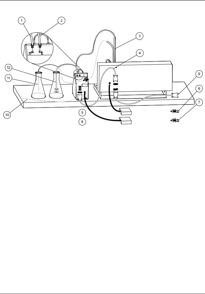
Ideally, the modules are configured in the following left-to-right order: computer (with peripherals), sampler, PDS200 Dilutor, reagent pump and system unit (refer to Figure 1).
Note: The sampler and dilutor can be placed on top of the optional shelf accessory in order to conserve bench space.
Figure 1 QuikChem FIA overview
1 |
Autosampler |
5 |
Computer and peripherals |
|
|
|
|
2 |
Dilutor (in rear) |
6 |
Power cords |
|
|
|
|
3 |
Pump |
7 |
Communication cables |
|
|
|
|
4 |
System unit |
|
|
|
|
|
|
The bench space required for a QuikChem® FIA System with up to five channels, dilutor, sampler, computer and printer is:
•Width: 2.72 m (9 ft)
•Depth: 0.83 m (2.75 ft)
•Height: 0.58 m (2 ft)
5

Specifications
1.2 Module dimensions
Table 1 contains the general dimensions for individual modules. Use Table 1 for any system configuration that differs from the one explained above.
Table 1 Dimensions
Module |
Width (cm)1 |
Depth (cm)1 |
Height (cm)1 |
Weight (kg)2 |
PDS200 |
12.7 |
22.5 |
23.4 |
4 |
|
|
|
|
|
ASX-500 sampler3 |
52.5 |
46 |
25 |
10 |
ASX-400 sampler |
16 |
14 |
16.5 |
7.3 |
|
|
|
|
|
Reagent pump (12 position) |
15 |
26 |
13 |
5.6 |
|
|
|
|
|
System unit (5 channels) |
70.5 |
71.2 |
26.7 |
46.5 |
|
|
|
|
|
SPM |
69 |
9 |
26 |
4 |
|
|
|
|
|
1Divide dimension by 2.54 to convert to inches.
2Multiply weight by 2.2 to convert to pounds.
3Allow an extra 15 cm of height for probe clearance.
Allow a minimum of 10 cm of free space in the back of the instrument and between modules for cabling and tubing. This extra space also offers easy access to the system components.
Note: To allow convenient access to the top and rear of the system, avoid putting the system under shelving.
1.3Electrical and environmental specifications
•Connect all modules to a surge-protected power strip.
Note: Refer to the back of the modules for the proper requirement.
•This equipment is intended for use in a laboratory.
•Use cables and power cords supplied by the manufacturer only.
Figure 2 shows the single phase voltage and frequencies worldwide and Table 2 describes the electrical specifications for the instrument modules.
Table 3 describes the environmental specifications for the instrument modules.
Figure 2 General guide to single phase voltage and frequencies worldwide
6

|
|
|
|
|
|
|
Specifications |
|
|
|
|
|
|
|
|
|
Table 2 Individual electrical specifications |
|
|||||
|
|
|
|
|
|
|
|
|
|
|
|
|
Maximum active |
|
|
|
|
|
|
|
power (W), |
|
|
Module |
AC input voltage |
|
AC input frequency |
apparent power |
|
Fuse rating |
|
rating or range |
|
rating or range |
(VA) or current |
|
|||
|
|
|
|
||||
|
|
|
|
|
(A) |
|
|
|
|
|
|
|
rating |
|
|
|
|
|
|
|
|
|
|
PDS200 |
110–240 VAC |
|
50–60 Hz |
0.5 A |
|
T, ½ A, 250 V |
|
|
|
|
|
|
|
|
|
ASX-500 sampler |
100–240 VAC |
|
50–60 Hz |
1.5 A |
|
Fuse not |
|
|
|
user-replaceable |
|||||
|
|
|
|
|
|
|
|
|
|
|
|
|
|
|
|
ASX-400 sampler |
100–120 VAC |
|
50–60 Hz |
200 VA |
|
Fuse not |
|
|
|
user-replaceable |
|||||
|
|
|
|
|
|
|
|
Reagent pump |
100 or 120 VAC |
|
50–60 Hz |
15 VA |
|
T, ½ A, 250 V |
|
|
|
|
|
|
|
|
|
220 or 240 VAC |
|
50–60 Hz |
15 VA |
|
T, ¼ A, 250 V |
||
|
|
|
|||||
|
|
|
|
|
|
|
|
System unit |
100–115 V ± 10% |
|
50–60 Hz |
800 W |
|
T, 8 A, 250 V |
|
|
|
|
|
|
|
|
|
230 V ± 10% |
|
50–60 Hz |
800 W |
|
T, 4 A, 250 V |
||
|
|
|
|||||
|
|
|
|
|
|
|
|
|
|
Table 3 Environmental specifications |
|
||||
|
|
|
|
|
|
||
Temperature |
|
|
|
15–35 °C (60–95 °F) |
|
||
|
|
|
|
|
|
||
Use |
|
|
|
Laboratory |
|
||
|
|
|
|
|
|
||
Altitude |
|
|
|
Up to 10,000 feet (3 km) above sea level |
|
||
|
|
|
|
|
|
||
Relative humidity |
|
|
|
Up to 92.5% non-condensing |
|
||
|
|
|
|
|
|
|
|
Pollution degree |
|
|
|
|
II |
|
|
|
|
|
|
|
|
|
|
Installation category |
|
|
|
|
II |
|
|
|
|
|
|
|
|
||
|
|
Table 4 Certifications |
|
|
|
||
|
|
|
|
|
|
|
|
Certification Marks |
|
Standards |
|
|
|
|
|
|
|
|
|||||
CE |
|
IEC/EN 61010-1 per LV Directive (2006/95/EC), IEC/EN 61326 per EMC: Directive |
|||||
|
(2004/108/EC |
|
|
|
|
||
|
|
|
|
|
|
||
cETL |
|
CSA C22.2 No 61010-1 |
|
|
|
||
|
|
|
|
|
|
|
|
ETLus |
|
UL 61010-1 |
|
|
|
|
|
|
|
|
|
|
|
|
|
7

Specifications
8
Section 2 General Information
2.1 Safety information
Read this entire manual before unpacking, setting up or operating this equipment. Pay attention to all danger and caution statements. Failure to do so could result in serious injury to the operator or damage to the equipment.
To make sure that the protection provided by this equipment is not impaired, do not use or install this equipment in any manner other than that specified in this manual.
2.1.1 Use of hazard information
DANGER
Indicates a potentially or imminently hazardous situation which, if not avoided, will result in death or serious injury.
WARNING
Indicates a potentially or imminently hazardous situation which, if not avoided, could result in death or serious injury.
CAUTION
Indicates a potentially hazardous situation that may result in minor or moderate injury.
Important Note: Indicates a situation which, if not avoided, may cause damage to the instrument. Information that requires special emphasis.
2.1.2 Precautionary labels
Read all labels and tags attached to the instrument. Personal injury or damage to the instrument could occur if not observed. A symbol, if noted on the instrument, will be included with a danger or caution statement in the manual.
This is the safety alert symbol. Obey all safety messages that follow this symbol to avoid potential injury. If on the instrument, refer to the instruction manual for operation or safety information.
This symbol indicates that a risk of electrical shock and/or electrocution exists.
This symbol identifies the location of a fuse or current limiting device.
This symbol, when noted on the product, indicated that the marked item can be hot and should not be touched without care.
This symbol, when noted on the product, indicated the presence of devices sensitive to Electro-static Discharge (ESD) and indicate that care must be taken to prevent damage with the equipment.
This symbol, when noted on the product, identifies a risk of chemical harm and indicates that only individuals qualified and trained to work with chemicals should handle chemicals or perform maintenance on chemical delivery systems associated with the equipment.
This symbol, if noted on the product, indicates the need for protective eye wear.
This symbol, when noted on the product, identifies the location of the connection for Protective Earth (ground).
Electrical equipment marked with this symbol may not be disposed of in European public disposal systems after 12 August of 2005. In conformity with European local and national regulations (EU Directive 2002/96/EC), European electrical equipment users must now return old or end-of life equipment to the Producer for disposal at no charge to the user.
Note: For return for recycling, please contact the equipment producer or supplier for instructions on how to return end-of-life equipment, producer-supplied electrical accessories, and all auxiliary items for proper disposal.
9

General Information
2.2 General product information
The system unit manages five sample processing modules or channels, configured for performing flow injection analysis with photometric detection. The number of channels can be expanded to a maximum of eight by adding a second core. Alternate configurations, such as potentiometric and amperometric detection methods are described in the analytical method where they are required. For complete information on the software, refer to the QuikChem FIA Omnion® Software Manual or the on-line help system in the software.
The QuikChem® 8500 Series 2 analyzer is modular in design (Figure 3) and consists of the following modules:
•Dilutor (optional)—The PDS200 uses positive displacement to draw diluent water to mix with non-flammable samples for analysis. Refer to section 3.4 on page 25.
•Sampler—The QC8500 Analyzer works with either the ASX-400 or ASX-500 series autosamplers. Refer to section 3.3 on page 21.
•Reagent Pump (12 or 16 cartridges)—The multichannel peristaltic pump is used to pump reagents into the manifold. It also aspirates sample aliquots from the sampler to the valve. These portions are then loaded into the sample loop and swept into the manifold by the carrier stream to mix with the reagents.
•QuikChem FIA System Unit—The System Unit consists of the core unit and the sample processing modules (SPM). The core unit distributes power, light and electronic signals to and from each SPM. A sample processing module, also known as a channel, typically consists of an injection valve, a manifold, a photometric detector and a heating module (optional). A System Unit can have up to five channels that run simultaneously. A single computer can control two System Units in order to run up to eight channels at once. A chemical reaction module or manifold is installed on a channel for the quantitative analysis of an analyte. There are more than 450 QuikChem methods available for determining over 40 analytes; many of them in several matrices.
•Computer
•Printer (optional)
Note: If any items are missing or damaged, contact the manufacturer or sales representative immediately. Ship the components returned for service in the original packaging material to protect against damage during transportation.
Note: The Ion Chromatography option is available with this instrument. Refer to the QuikChem Ion Chromatography User Manual for instructions.
Figure 3 QuikChem® FIA automated ion analyzer with shelf (Catalog No. 31079)
10
Section 3 |
Installation |
DANGER
Only qualified personnel should conduct the tasks described in this section of the manual.
3.1 System unit installation
3.1.1 Carrying instructions
CAUTION
Potential Lifting Hazard. A five-channel system weighs 47 kg (103 lb). Do not unpack, carry or move the system without proper equipment or sufficient number of people. Make sure that the system is lifted with leg support and not back support. People with a history of back problems or cardiovascular problems are prohibited to lift, move or unpack this system.
•Lift the System Unit and channels from the bottom. Do not lift by the front panel.
•Always support the entire instrument (e.g., with a cart or a board) during transport.
3.1.2Connect the power strip
DANGER
Electrical Shock Hazard. The facility circuit breaker rating must not exceed 20 A.
DANGER
Electrical Shock Hazard. A good low impedance earth ground connection is required to the equipment cord plug.
DANGER
Potential Electrocution Hazard. If equipment is to be used in wet or potentially wet locations, always connect to power via an outlet with a Ground Fault interrupt Circuit (GFIC) or a residual Current Circuit Breaker.
To connect the power strip:
1.Connect the power strip to a power supply.
2.Position the power strip on the bench so that other components can be connected.
3.Leave the power strip off during the installation of other system components.
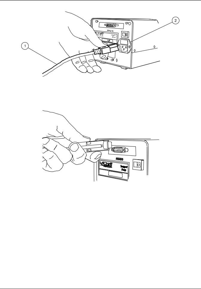
3.1.3Connect the system unit
Note: Do not position the equipment in any way that will prevent access to the On/Off switch. Refer to Figure 4 on page 12, item 1.
To connect the system unit:
1.Connect the power cord to the power outlet on the left side of the System Unit (Figure 4 on page 12). Connect the other end of the power cord to the power strip. Leave the power strip switch off.
2.Locate the 9-pin connector of the cable attached to the reagent pump. Plug this connector in the outlet for Pump 1 (Figure 4 on page 12, item 4) on the interface panel, located on the left side of the System Unit.
3.Connect one USB cable to the outlet labeled USB In. The other end will connect to the computer.
11
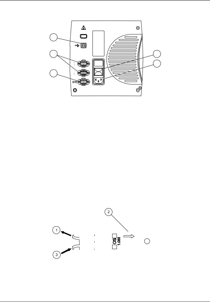
Installation
5 |
4 |
3 |
 1
1
 2
2
1 |
2 |
|
Figure 4 |
System unit connection |
||
1 |
On/Off switch |
|
4 |
Pump connectors |
|
|
|
|
|
2 |
Power for system unit |
|
5 |
USB in (from computer) |
|
|
|
|
|
3 |
High pressure pump (IC only) |
|
|
|
|
|
|
|
|
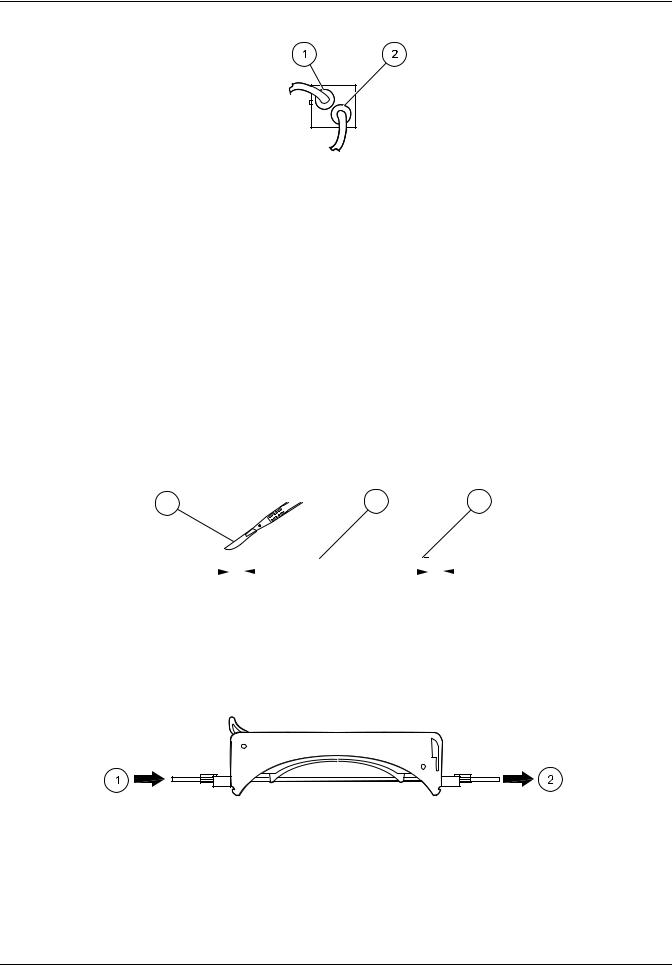
3.1.4 Flow cell installation
To install the flow cell:
1.Insert the flow cell into the detector with the printed side (bottom) down. Since the flow cell is keyed, insert the flow cell only in the corresponding slot of the detector (Figure 5).
2.Make sure the flow cell is pushed all the way in the slot. The bottom flared tubing connector on the flow cell is the inlet and the top connector is the outlet. During the installation of a manifold (reaction module), it is very important to make the connections accordingly, so air bubbles do not get trapped in the flow cell. Refer to Figure 6 on page 13.
3.Connect the top connector (outlet) to the waste line.
|
|
|
|
|
|
|
|
|
|
|
|
|
|
|
|
|
|
|
|
|
|
|
|
|
|
|
|
|
|
|
|
|
|
|
|
|
|
|
|
|
|
|
|
|
|
|
|
|
|
|
|
|
|
Figure 5 |
Flow cell |
||||||||||||
|
|
|
|
|
|
|
|
|
|
|
|
|
|
|
|
|
1 |
To waste |
3 Inlet |
||||||||||||||
|
|
|
|
|
|
|
|
|
|
|
|
|
|
|
|
|
2 |
Flow cell body |
|
|
|
|
|
|
|
|
|
|
|||||
|
|
|
|
|
|
|
|
|
|
|
|
|
|
|
|
|
12
Installation
Figure 6 Flow cell connectors
1 To waste |
2 Inlet (from manifold) |
|
|
3.1.5 Waste and sample line installation
3.1.5.1 Sample line
A sample line consists of a union connector, 130 or 190 cm of Teflon® tubing 0.8 mm (0.032 in.) ID, two pump tube adapters, a green-green pump tube with its ends trimmed to 2 cm past both green tabs and 30 cm of Teflon tubing 0.8 mm (0.032 in.) ID.
To install the sample line:
1.Trim the ends of a green-green pump tube to 2 cm past both green tabs (Figure 7). This procedure only applies to the green-green pump tube used in a sample line. All other pump tubes do not need to be trimmed.
Note: Refer to the QuikChem method to find the pump tube color to be used as a sample line. Most manifolds will use a green-green pump tube, but there are some exceptions.
1 |
2 |
3 |
|
|
|
|
|
|
|
|
|
|
|
|
|
|
|
|
|
|
|
|
|
|
|
|
|
|
|
|
|
|
|
|
|
|
20 mm |
|
|
|
|
|
|
|
|
|
20 mm |
|||
|
|
|
|
|
|
|
|
|
|
|
|
|
|
|
|
|
|||||||
|
|
|
|
|
|
|
|
|
|
[0.79 in] |
|
|
|
[0.79 in] |
|||||||||
|
Figure 7 Trimming the green-green pump tube |
||||||||||||||||||||||
|
|
|
|
|
|
|
|
|
|
|
|
|
|
|
|
|
|
|
|
|
|
|
|
1 Scalpel |
|
|
|
|
|
2 Green-green pump tube |
|
3 Green tab (2x) |
|||||||||||||||
|
|
|
|
|
|
|
|
|
|
|
|
|
|
|
|
|
|
|
|
|
|
|
|
2.Attach the sample line pump tube on a pump tube cartridge (Figure 8). Do not clamp down the cartridge on the pump. Refer to Section 4 on page 29 for further details.
Figure 8 Sample line pump tube and cartridge
1 From probe |
2 To injection valve |
|
|
3.Connect the 30 cm Teflon tubing to port 6 of the injection valve.
4.Connect the 130 or 190 cm Teflon tubing to the probe on the sampler.
13
Installation
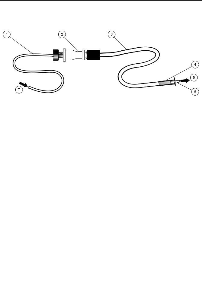
3.1.5.2 Waste line
A waste line consists of a 13 cm of Teflon tubing 0.8 mm ID, a pump tube adapter, 150 cm of Tygon tubing 1.5 mm ID, a glass weight and a plastic nipple. Refer to Figure 9.
|
Figure 9 |
Waste line |
||
1 |
13 cm Teflon 0.8 mm ID |
|
5 |
To waste container |
|
|
|
|
|
2 |
Adapter |
|
6 |
Nipple |
|
|
|
|
|
3 |
150 cm Tygon 1.5 mm ID |
|
7 |
From flow cell or valve (port 5) |
|
|
|
|
|
4 |
Glass weight |
|
|
|
|
|
|
|
|
To install a waste line:
1.Connect a waste line to port 5 of the injection valve and the top connector of the flow cell.
2.When running two or more channels simultaneously, interconnect adjacent valves by installing 15 cm of 0.8 mm Teflon tubing between ports 5 and 6 (Figure 10 on
page 15). The waste channel farthest from the System Unit will drain directly into the waste container. Refer to Section 4 on page 29 for details.
14
Installation
|
|
|
|
|
|
|
|
|
|
|
|
|
|
|
|
|
|
|
|
|
|
|
|
|
|
|
|
|
|
|
|
|
|
|
|
|
|
|
|
|
|
|
|
|
|
|
|
|
|
|
|
|
|
|
|
|
|
|
|
|
|
|
|
|
|
|
|
|
|
|
|
|
|
|
|
|
|
|
|
|
|
|
|
|
|
|
|
|
|
|
|
|
|
|
|
|
|
|
|
|
|
|
|
|
|
|
|
|
|
|
|
|
|
|
|
|
|
|
|
|
|
|
|
|
|
|
|
|
|
|
|
|
|
|
|
|
|
|
|
|
|
|
|
|
|
|
|
|
|
|
|
|
|
|
|
|
|
|
|
|
|
|
|
|
|
|
|
|
|
|
|
|
|
|
|
|
|
|
|
|
|
|
|
|
|
|
|
|
|
|
|
|
|
|
|
|
|
|
|
|
|
|
|
|
|
|
|
|
|
|
|
|
|
|
|
|
|
|
|
|
|
|
|
|
|
|
|
|
|
|
|
|
|
|
|
|
|
|
|
|
|
|
|
|
|
|
|
|
|
|
|
|
|
|
|
|
|
|
|
|
|
|
|
|
|
|
|
|
|
|
|
|
|
|
|
|
|
|
|
|
|
|
|
|
|
|
|
|
|
|
|
|
|
|
|
|
|
|
|
|
|
|
|
|
|
|
|
|
|
|
|
|
|
|
|
|
|
|
|
|
|
|
|
|
|
|
|
|
|
|
|
|
|
|
|
|
|
|
|
|
|
|
|
|
|
|
|
|
|
|
|
|
|
|
|
|
|
|
|
|
|
Figure 10 |
Flow injection connections |
||||||||||||||||||||
|
|
|
|
|
|
|
|
|
|
|
|
|
|
|
|
|
|
|
|
|
|
|
|
1 |
System unit |
|
|
|
|
|
5 |
|
|
|
Waste lines |
||||||||||||
|
|
|
|
|
|
|
|
|
|
|
|
|
|
|
|
|
|
|
|
|
|
|
|
2 |
Channel 1 |
|
|
|
|
|
6 |
|
|
|
Waste container |
||||||||||||
|
|
|
|
|
|
|
|
|
|
|
|
|
|
|
|
|
|
|
|
|
|
|
|
3 |
Channel 2 |
|
|
|
|
|
7 |
|
|
|
Waste line |
||||||||||||
|
|
|
|
|
|
|
|
|
|
|
|
|
|
|
|
|
|
|
|
|
|
|
|
4 |
Channel 3 |
|
|
|
|
|
8 |
|
|
|
Sample line |
||||||||||||
|
|
|
|
|
|
|
|
|
|
|
|
|
|
|
|
|
|
|
|
|
|
|
|
3.Place the glass weight end of the waste line in a proper waste container. Never submerge the waste line in the waste solution because this may cause back pressure and flow restrictions. Make sure the waste solution always drips into the container.
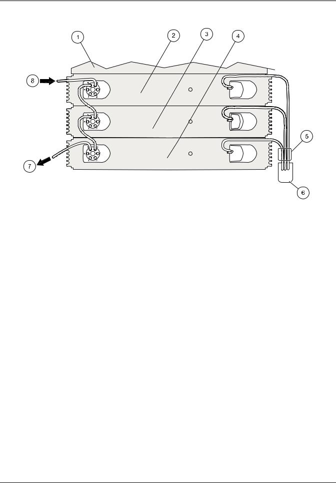
3.1.6Manifold installation
The manifold is the reaction module where the chemistry occurs.
Specific installation requirements are detailed in the Figure 28 on page 32 included with each chemistry method. Refer to Figure 11 on page 16 and the following steps to install the manifold for flow injection analysis.
To install the manifold:
1.On the valve, connect port 1 to port 4 with the sample loop.
2.Connect the manifold outlet to the flow cell inlet (Figure 11 on page 16, item 6).
3.Install the interference filter (Figure 11 on page 16, item 5).
4.Connect the carrier line to port 2 on the valve (Figure 11 on page 16, item 8).
5.Connect the tubing from port 3 to the connector labeled From Valve.
6.Attach one end of a waste line to the flow cell outlet. Drop the other end into a waste container (Figure 11 on page 16, item 4).
15

Installation
|
|
|
|
|
|
|
|
|
|
|
|
|
|
|
|
|
|
|
|
|
|
|
|
|
|
|
|
|
|
|
|
|
|
|
|
|
|
|
|
|
|
|
|
|
|
|
|
|
|
|
|
|
|
|
|
|
|
|
|
|
|
|
|
|
|
|
|
|
|
|
|
|
|
|
|
|
|
|
|
|
|
|
|
|
|
|
|
|
|
|
|
|
|
|
|
|
|
|
|
|
|
|
|
|
|
|
|
|
|
|
|
|
|
|
|
|
|
|
|
|
|
|
|
|
|
|
|
|
|
|
Figure 11 |
Flow injection analysis |
||||||||||||||
|
|
|
|
|
|
|
|
|
|
|
|
|
|
|
|
|
|
|
|
|
1 |
Sample line |
|
|
6 |
From manifold outlet |
|||||||||||||||
|
|
|
|
|
|
|
|
|
|
|
|
|
|
|
|
|
|
|
|
|
2 |
Sample loop |
|
|
7 |
Manifold configuration varies |
|||||||||||||||
|
|
|
|
|
|
|
|
|
|
|
|
|
|
|
|
|
|
|
|
|
3 |
To manifold inlet |
|
|
8 |
Carrier line |
|||||||||||||||
|
|
|
|
|
|
|
|
|
|
|
|
|
|
|
|
|
|
|
|
|
4 |
To waste |
|
|
9 |
Waste or next valve |
|||||||||||||||
|
|
|
|
|
|
|
|
|
|
|
|
|
|
|
|
|
|
|
|
|
5 |
Interference filter |
|
|
|
|
|
|
|
|
|
|
|
|
|
||||||
|
|
|
|
|
|
|
|
|
|
|
|
|
|
|
|
|
|
|
|
|
3.1.7 Data system installation
Follow the manufacturer’s instructions for the setup of the computer, keyboard, monitor and mouse.
For Data Systems purchased from the manufacturer, the Omnion software is installed at the factory.
For customer-supplied systems, refer to the Omnion User Guide for software installation instructions.
3.2 Pump installation and power up
3.2.1 Pump installation
To install the pump:
1.Set the pump on the bench (Figure 3 on page 10 and Figure 1 on page 5).
2.Connect the power cord to the power strip. Leave the power strip switch off.
3.Connect the power cord to the mains supply socket on the back of the pump (Figure 12 on page 17).
16
Installation
Figure 12 |
Power cord connection |
|
1 Power cord |
|
2 Main supply socket |
|
|
|
4. Connect the analog cable to the back of the pump (Figure 13).
Figure 13 Analog cable connection
5.Connect the other side of the analog cable to the left panel of the QuikChem System Unit. Refer to section 3.1.3 on page 11.
17

Installation
3.2.2 Apply power to the pump
To apply power to the pump:
1.Turn on the power strip, then turn on the power switch on the back of the pump (Figure 14). In an RP-150 Model pump, the top panel will show the set speed of 35.
Figure 14 Power switch location
1 Power switch
3.2.3 Pump tubing installation
To install the pump tubing:
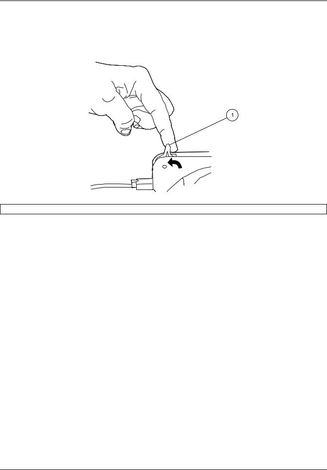
1.Remove all of the pump cartridges. Press the cartridge holder against the pump, then lift the cartridges out (Figure 15).
Figure 15 |
Pump cartridge removal |
|
1 Cartridge |
|
2 Cartridge holder |
|
|
|
|
|
|
18
Installation
2.Place the pump tubing on the cartridges (Figure 16). Make sure that the tabs lock into the adaptor.
1 |
2 |
3 |
4 |
|
7 |
|
5 |
|
|
|
|
|
6 |
|
|
|
Figure 16 |
Placement of pump tubing on the cartridges |
|
1 |
Tension lever |
5 |
To injection valve or |
2 |
Pump tube cartridge |
6 |
Pump tube |
3 |
Adapter |
7 |
From probe or reagent |
4 |
Pump tube tab |
|
|
3.Move the tension lever to the far right position (Up position).
4.Install the pump cartridge. Engage one side of the cartridge on the cartridge holder, then clamp down the other side (Figure 17). The tension levers are always on the left side of the pump. An arrow indented on top of the cartridges shows the flow direction. Make sure the pump is moving when the cartridge is clamped down.
Figure 17 Pump cartridge installation
19
Installation
5.Move the tension lever to the left until it clicks into place (Figure 18). Make sure the tension lever is in the 12 o'clock position.
Note: Move the lever to the right to remove tension.
6.Store unused cartridges.
Figure 18 Tension lever setup
1 One click back
3.2.4 Reagent pump initial test
To test the reagent RP-150 pump:
1.Make sure that the Omnion software is not active at this time. Press the NORMAL RUN button. Make sure the pump is running at a normal speed of 35. The NORMAL LED will be illuminated. If the display shows a different speed, press the ARROW button to change the setting to 35.
2.Press the MIN button. The MIN LED will be illuminated. The display will show a speed of 4.
3.Hold down the MAX button until the MAX LED is illuminated. The display will show a speed of 999. The pump will go back to the original speed when the MAX button
is released.
4.To stop the pump, press the MANUAL RUN/ STOP button. No LEDs will be illuminated, but the display will show “35” (the pump speed).
5.Press the MANUAL RUN/ STOP button again. The MANUAL LED will be illuminated. The pump will be running at normal speed of 35.
6.Press the MANUAL RUN/ STOP button to stop the pump. To repeat any of the steps above, turn off the pump and start with step 1.
7.If any of the above steps fail, contact Technical Support or a local sales representative.
Note: Contact Technical Support for queries regarding the installation and testing of a different peristaltic pump model.
20
Installation
3.3 Sampler installation
3.3.1 Sampler type
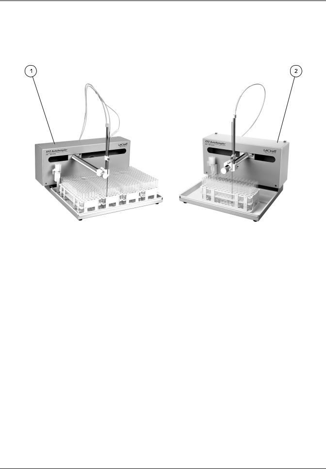
The QuikChem 8500 Series 2 can be used with either the ASX-500 Series Sampler or the ASX-400 Series Sampler (Figure 19). Installation is the same for both samplers.
Figure 19 |
Autosamplers |
|
1 ASX-500 Autosampler |
|
2 ASX-400 Autosampler |
|
|
|
3.3.2 Unpack the ASX sampler
Note: If any of these items are missing or damaged, contact the manufacturer or sales representative immediately. Ship the instruments returned for service in the original packaging material to protect against damage during transportation.
ASX samplers are shipped with:
•Sample tray(s), assembled and installed
•Probe tube in styrofoam container
•Tubing kit with waste line, sample line and probe
To unpack the sampler:
1.Remove the sampler from the shipping carton and protective plastic and place on the laboratory bench.
2.Remove the probe arm from the styrofoam container and lay carefully on top of the sample racks.
3.Open the tubing kit and identify the components required for fluidic connections.
21

Installation
3.3.3 Sampler setup
To connect the sampler:
1.Connect the power cord to the power strip. Leave the power strip switched off.
2.Connect the supplied RS232C cable to the 9-pin connector (COM1) on the back of the sampler.
3.Connect the other end of the RS232C cable to COM1 on the computer.
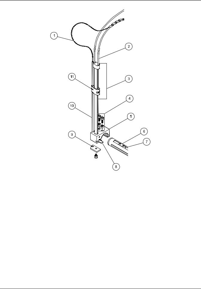
3.3.4Mount Z-drive
Except for the Z-drive, the sampler is assembled at the factory.
To mount the Z-drive on the sampler arm:
1.Remove thumbscrews and bushings from the drive block located on the sampler arm (Figure 20 on page 23).
2.Attach the x-axis slider block on the arm tube.
3.Secure the slider block finger-tight with the 12-mm thumbscrews (installed from the top).
3.3.5Probe installation
To install the probe:
1.Loosen the probe knob on the probe tube slider and remove the piece of tubing installed for shipping. Lift the probe tube slider until it stops.
Note: The tan knob will come off without the tubing or probe to hold it in place.
2.The guide slider will move to the upper position with the probe tube slider. Use the wheel in the back of the sampler to lower both sliders until the guide slider is about 1 mm from the top. Make sure that the two sliders are in contact.
Note: Always move the sliders using the wheel at the back of the sampler to avoid crimping the PEEK tubing.
3.Install the sample probe through both sliders, the probe knob and the opening on the probe guide plate. Keep the sliders about 1 mm from the top. Adjust the probe so the tip is 3 to 6 mm below the guide plate. To secure the probe, tighten the probe knob on the probe tube slider.
4.Move the sampler arm to the rinse station (extreme left position in the standards rack). Verify if the probe tip clears the top of the rinse station when the sampler is in the home position.
22
Installation
Figure 20 Probe tube assembly
1 |
Sample transfer tubing |
7 |
Slider block guide rail |
|
|
|
|
2 |
Sipper assembly tube |
8 |
Home position flag |
|
|
|
|
3 |
Z-drive assembly |
9 |
Sample probe guide plate |
|
|
|
|
4 |
Thumbscrews with bushings |
10 |
Z-axis slider |
|
|
|
|
5 |
X-axis block |
11 |
O-ring |
|
|
|
|
6 |
Y-axis lead screw |
|
|
|
|
|
|
23

Installation
3.3.6 Fluidic connections
3.3.6.1 Connect the rinse station
Rinse solution is pumped into the bottom of the rinse station and drains to a waste container through drain tubing attached at the top of the station (Figure 21).
To connect the rinse station:
1.Connect the rinse-in end of the wash line assembly to the inlet fitting (bottom).
2.Install the pump tube with the purple pump tube tabs on the pump. Refer to section 3.2.3 on page 18.
Note: The outlet of the tube on the right side of the pump attaches to the inlet of the wash bath (Figure 21, item 1).
Important Note: Do not lock down the right side of the pump cartridge until ready to perform the test.
3.Drop the other end of the wash line into the rinse solution.
4.Connect one end of the Tygon drain tubing to the drain fitting (top). Drop the other end into a waste container.
|
Figure 21 |
Rinse station diagram |
||
1 |
Drain fitting |
|
5 |
Inlet fitting |
2 |
Wash bath |
|
6 |
Rinse-in tubing |
3 |
Mounting block |
|
7 |
From pump |
4 |
Flow |
|
8 |
Drain tubing for waste |
3.3.6.2 Sample line installation (no dilutor)
To install the sample line:
1.Connect the end of the sample line with the union fitting to the probe.
2.Install the pump tubing (green collar locks) in the pump. Refer to section 3.2.3 on page 18.
Note: Do not lock down the right end of the pump tubing.
3.Connect the sample line to the injection valve on the system unit.
24
Installation
3.3.7 Connect the sampler to a PDS200 dilutor
Systems that use a PDS200 dilutor require the ASX-500 Series Sampler and a dual probe. Refer to section 3.4 for installation instructions.
3.4 Dilutor installation
The PDS200 uses positive displacement to draw deionized water or other diluent to mix with non-flammable samples for analysis.
For operation, the PDS200 dilutor requires:
•An ASX-500 Series autosampler with upgraded firmware, ASX-500 Series serial number 080313 or greater. For older ASX-500 samplers, contact Technical Support.
•Installation of Omnion 3.0.218 or higher.
3.4.1Cable connections
To install the dilutor:
1.Make sure that the dilutor power switch is off (Figure 22).
2.Turn off and disconnect the power strip.
3.Connect the Desktop Power Supply with power cable (Catalog No. 5011200) to the dilutor (Figure 22). Plug the other end into the power strip.
4.Connect the male connector of the 9-pin serial cable to the back of the dilutor (Figure 22). Connect the other end to the dilutor port on the back of the autosampler.
|
Figure 22 |
PDS200 dilutor |
||
1 |
Power indicator light |
|
4 |
Power cable connector |
|
|
|
|
|
2 |
On/Off switch |
|
5 |
Solenoid valve |
|
|
|
|
|
3 |
Serial cable connector |
|
|
|
|
|
|
|
|
25
Installation
3.4.2 PDS200 connections
Note: Probe speed on existing autosamplers has been reduced to improve performance. The autosampler may produce a different sound as a result.
To connect the PDS200:
1.Connect the DI Water Line to Port A of the solenoid valve of the dilutor. Place the other end of the line into the DI water (Figure 23).
2.Connect the Sample Line Assembly to port B of the solenoid valve (Figure 23, item 3).
3.If necessary, attach the Dual Probe Assembly to the autosampler. The probe guide may need to be rotated to accommodate the dual probe.
4.Connect the probe sample line (attached to the bent tube of the Dual Probe Assembly) to port C of the solenoid valve (Figure 23, item 5).
5.Make sure the ferrule on the line from the straight tube of the Dual Probe Assembly is flush with the end of the tubing (Figure 23, item 2).
6.Insert the connector from the straight tube of the Dual Probe Assembly into port D of the dilutor (Figure 24 on page 27) and tighten.
7.Make sure the ferrule on the dilutor end of the Diluent Line Filter Assembly is flush with the end of the tubing (Figure 23, item 2).
8.Insert the connector from the Diluent Line Filter Assembly into port E of the dilutor and tighten (Figure 23, item 3).
9.Insert the filter end of the Diluent Line Filter Assembly into the diluent (Figure 23, item 2).
1 |
5 |
|
|
|
2 |
|
4 |
3 |
|
|
|
|
|
|
Figure 23 |
Tubing connectors and ferrule placement |
|
1 |
Ferrule |
4 |
To DI water port A |
2 |
Flush |
5 |
To sample probe line port C |
3 |
To pump/analyzer port B |
|
|
26
Installation
|
|
|
|
|
|
|
|
|
|
|
|
|
|
|
|
|
|
|
|
|
|
|
|
|
|
|
|
|
|
|
|
|
|
|
|
|
|
|
|
|
|
|
|
|
|
|
|
|
|
|
|
|
|
|
|
|
|
|
|
|
|
|
|
|
|
|
|
|
|
|
|
|
|
|
|
|
|
|
|
|
|
|
|
|
|
|
|
|
|
|
|
|
|
|
|
|
|
|
|
|
|
|
|
|
|
|
|
|
|
|
|
|
|
|
|
|
|
|
|
|
|
|
|
|
|
|
|
|
|
|
|
|
|
|
|
|
|
|
|
|
|
|
|
|
|
|
|
|
|
|
|
|
|
|
|
|
|
|
|
|
|
|
|
|
|
|
|
|
|
|
|
|
|
|
|
|
|
|
|
|
|
|
|
|
|
|
|
|
|
|
|
|
|
|
|
|
|
|
|
|
|
|
|
|
|
|
|
|
|
Figure 24 |
Dilutor and solenoid valve fluidic connections |
||||||||||||||||
|
|
|
|
|
|
|
|
|
|
|
|
|
|
|
|
|
|
|
1 |
To sample probe |
|
|
|
|
7 |
Dilutor power connection |
|||||||||||
|
|
|
|
|
|
|
|
|
|
|
|
|
|
|
|
|
|
|
2 |
To diluent |
|
|
|
|
8 |
Dilutor power supply |
|||||||||||
|
|
|
|
|
|
|
|
|
|
|
|
|
|
|
|
|
|
|
3 |
Dual probe assembly |
|
|
|
|
9 |
Sampler power supply |
|||||||||||
|
|
|
|
|
|
|
|
|
|
|
|
|
|
|
|
|
|
|
4 |
Dilutor/sampler serial cable |
|
|
|
|
10 |
To pump/analyzer |
|||||||||||
|
|
|
|
|
|
|
|
|
|
|
|
|
|
|
|
|
|
|
5 |
Sampler/computer connection |
|
|
|
|
11 |
DI water line |
|||||||||||
|
|
|
|
|
|
|
|
|
|
|
|
|
|
|
|
|
|
|
6 |
Sampler power connection |
|
|
|
|
12 |
Diluent line filter assembly |
|||||||||||
|
|
|
|
|
|
|
|
|
|
|
|
|
|
|
|
|
|
|
27

Installation
28
 Loading...