

LAB-LINE 460, 460JPN, 460RH, 460-1, 460-1CE User manual
...
OPERATION MANUAL
AUTOMATIC CO2 INCUBATORS
MODEL NO. WATER-JACKETED AUTOMATIC CO2:
Models With Thermal Conductivity Sensor:
460, 460JPN, 460RH*, 460-1, 460-1CE, 462, 462-1,
462-1CE, 464, 464RH, 464-1, 464-1CE
Models With Infrared Sensor:
465, 465RH*, 465-1, 467, 467-1, 469, 469-1,
8/01
MANUAL NO. 057-588-00
REV. O
LAB-LINE
AIR-JACKETED AUTOMATIC CO
Models With Thermal Conductivity Sensor:
490, 490RH*, 490-1, 490-1CE, 492, 492-1, 492-1CE,
494, 494-1, 494-1CE
Models With Infrared Sensor:
495, 495JPN, 495RH*, 495-1, 497, 497-1, 499, 499-1
Models With Thermal Conductivity Sensor And Large Chamber Capacity:
391, 391-1, 391-2**, 391-3**
*With Relative Humidity Display
**With 3-Pen Strip Chart Recorder
DESIGNERS AND MANUFACTURERS
A SUBSIDIARY of Barnstead|Thermolyne
1999 North 15th Ave.
PHONE: (563) 556-2241 or (800) 522-5463; FAX: (563) 589-0516
, Melrose Park, IL 60160-1491 USA
2:

TABLE OF CONTENTS
2

SECTION TITLE
1 Introduction
2 Description
3 Specifications
4 Features
5 Installation
6 Operation
7 Maintenance
8 Replacement Parts
Warranty
3

BE ADVISED:
IT IS MOST IMPORTANT THAT THE USER FOLLOW INSTALLATION
INSTRUCTIONS EXACTLY AS WRITTEN. FAILURE TO DO SO IS LIKELY TO
LEAD TO IMPROPER OPERATION, ERRONEOUS CALIBRATIONS AND
POSSIBLE DAMAGE TO THE EQUIPMENT. UNDER NO CIRCUMSTANCES
SHOULD THE USER ATTEMPT OPERATION WITHOUT THIS INFORMATION.
THE FOLLOWING EQUIPMENT IS TO BE SUPPLIED BY THE USER:
• Dry CO2 gas (research grade or better).
• A dual-stage regulator for the CO2 tank.
• ¼" (6.35mm) ID Flexible tubing (appropriate length from tank to
Incubator), and connected per local codes.
• Distilled or deionized water (if humidification is desired).
• Fyrite or similar chemical-based CO2 analyzer.
BE ADVISED: INSTALLATION AND PRE-OPERATION PROCEDURE WI LL
TAKE AT LEAST 24 HOURS TO COMPLETE. DO NOT ATTEMPT TO RUSH
THE PROCESS WITH SHORT CUTS TO THE PROCEDURES DESCRIBED IN
THIS MANUAL.
4

CERTIFICATION OF DECONTAMINATION:
We cannot accept for service or credit a product that has been exposed
to or contaminated with chemically or biologically toxic or infectious substances
or subjected to radioactivity without first being certified as free from said
contamination.
Please have your Medical and/or Safety Officer sign this form certifying
that proper decontamination procedures have been followed to render the
product safe and free from hazards.
Any product forwarded to us, not accompanied by this form and a proper
Return Goods Authorization Number, will be returned to the sender. To obtain a
Return Goods Authorization Number, contact the Customer Relations
Department at (800) 522-5463.
We hereby certify that the LAB-LINE INSTRUMENTS, INC. product:
Model No. and Serial No. ,
that is being forwarded has been properly decontaminated and is free from all toxic
hazards, infectious agents, radioactivity and/or other hazards.
Company/Institution Name:
Street Address:
City: State Zip
Name (please print): Title
Signature:
Phone:
DECONTAMINATION PROCEDURE (Be Specific):
Nature of Hazard That Required Decontamination:
5

SECTION 1
6

INTRODUCTION
THANK YOU
for selecting Lab-Line Instruments for your equipment needs. For maximum value and
ease of start-up,
PLEASE PROCEED AS FOLLOWS:
• Inspect the carton and contents for shipping damage. Notify the carrier immediately
if damage is found.
• Use the Accessory Checklist when unpacking to verify that the complete unit has
been received. Do not discard packing materials until all is accounted for.
• Read this Operation Manual thoroughly before deciding upon an appropriate
location for the unit: you will want to consider, where applicable, the availability of
power, water, hook-ups, drains and other unit requirements, as well as user
convenience.
• Insist that every operator of this unit becomes familiar with the Operation Section of
this manual.
• Be sure to fill out the Warranty Registration Card and mail it in to Lab-Line
Instruments within seven (7) days after receiving the unit.
IF
after reading this manual you should have any difficulties with the installation or
operation instructions, please call:
Lab-Line Customer Relations Department
(563) 556-2241 or (800) 522-5463
ALL RIGHT RESERVED
The information contained in this manual is the exclusive property of Lab-Line Instruments, Inc., and has been provided solely to enable the users of the equipment described herein to operate and maintain such equipment. Any
other use of this information, or the reproduction or transmission of all or any portion of this manual without prior
written consent of the manufacturer is expressly prohibited. © 2001, Lab-Line Instruments, Inc.
SECTION 2
7
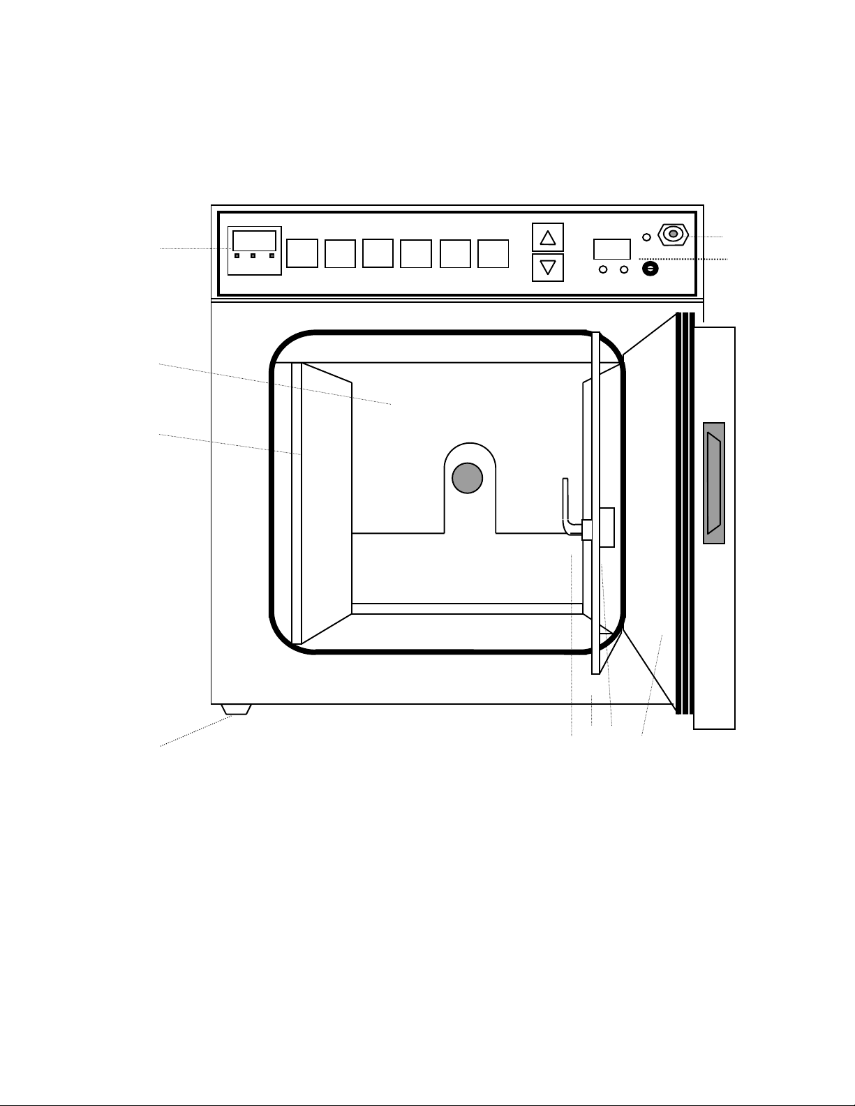
BASIC COMPONENTS, AN INITIAL OVERVIEW:
FRONT VIEW:
1
2
3
DESCRIPTION
9
10
4 567 8
1. CONTROL PANEL
2. REAR WALL COVER
3. SIDE PANEL
4. FEET, LEVELING
5. INNER GLASS DOOR
LATCH
DESCRIPTION: (Con’t)
6. INNER GLASS DOOR
7. INNER GLASS DOOR, KNOB
8. OUTER STEEL DOOR/GASKET
9. SAMPLE PORT
10. RH DISPLAY; MODELS 460RH, 490RH,
465RH, 495RH ONLY
8
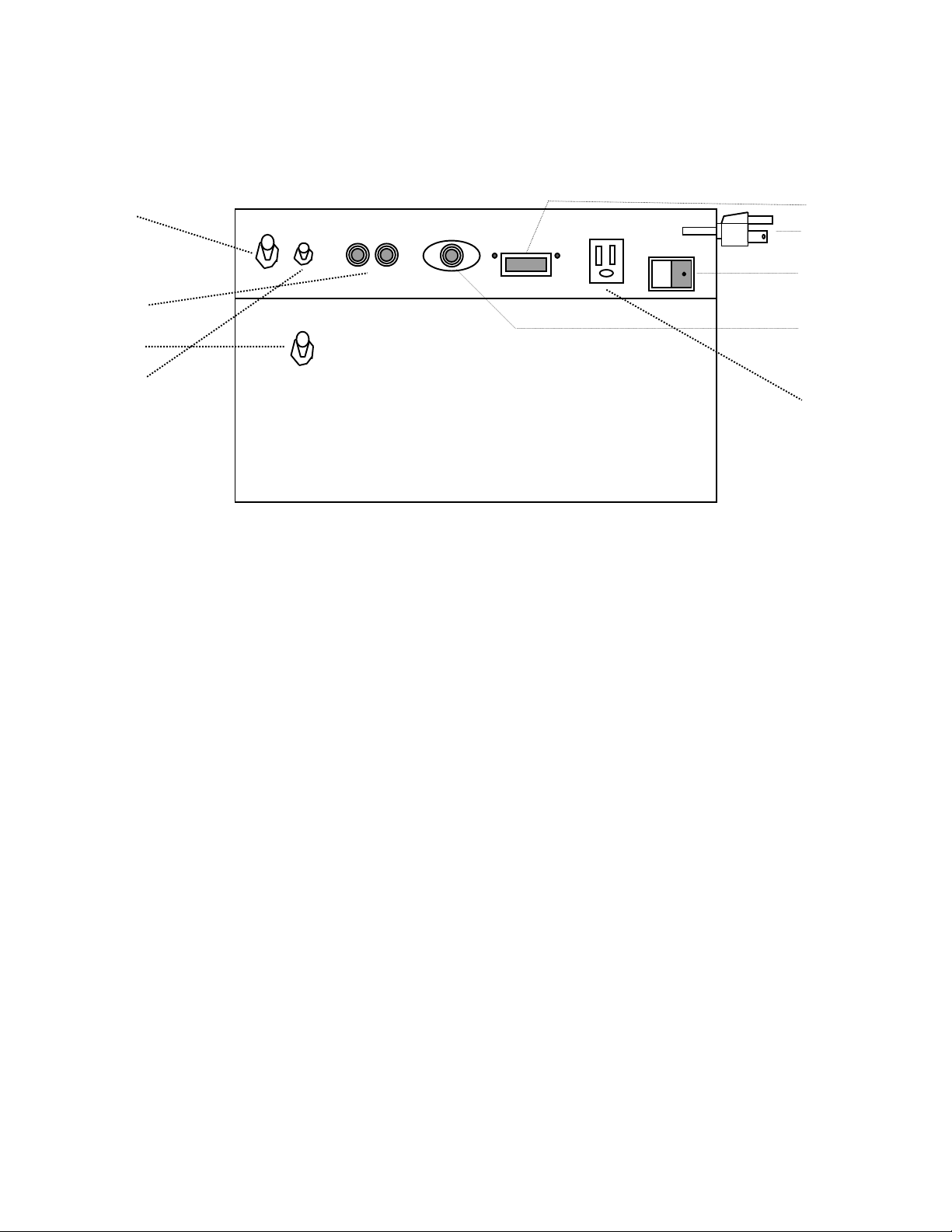
BASIC COMPONENTS, AN INITIAL OVERVIEW:
REAR VIEW
1 5
2
3
4
1. GAS INLET PORT
2. CIRCUIT BREAKERS
3. WATER OVERFLOW OUTLET (460/465 SERIES ONLY)
4. TOGGLE SWITCH FOR RH DISPLAY (460RH, 465RH, 490RH, 495RH)
5. RS232 DATA PINS CONNECTOR
6. CORDSET
7. POWER SWITCH
8. OPTIONAL ALARM RELAY OUTPUT
9. OUTLET (120 VAC UNITS ONLY)
(CON’T)
6
7
8
9
DESCRIPTION: (Con’t)
INFRARED CONTROL OF CO2
9

This sensor is impervious to relative humidity and is less susceptible to drift
and re-calibration. By measuring the absorption of infrared light within a CO2
atmosphere, the highest level of sensitivity is provided.
THERMAL-CONDUCTIVITY CONTROL OF CO2:
This sensor measures CO2 within an atmosphere by the heat of
conduction method and provides precise and reliable control.
SYSTEMS AND FEATURES:
All required operating commands are immediately accessible in a
functional format on the front of the unit and permit rapid start-up, close
monitoring and efficient control of incubation protocols.
Temperature is measured by platinum RTD (resistance temperature
detector) producing excellent control within ±0.1ºC. It is combined with the
exclusive SmartGas® algorithm method for controlling CO2 within ±0.1%. The
result is a chamber that produces excellent environmental conditions for the most
sensitive of incubations.
Air passes downward over the heated area and is then directed upward in a
gentle, uniform flow from the chamber floor. This upward draft inhibits the
contamination of cultures. If the temperature exceeds the set point by more than
the set point setting, power to the heaters is discontinued.
Audible and visual alarms alert the user of any deviation in the chamber of
temperature (±1.0°C or better) or carbon dioxide (±1.0°%). In addition, other
signals alert the user of such conditions as power failure, door ajar and low water
on water jacketed models.
To conserve gas, the CO2 solenoid valve shuts off automatically any time
the insulated, incubator door is opened. The fan motor shuts off during door
openings as well.
Required operating commands are immediately accessible in a functional
format on the front of the unit and permit rapid start-up, close monitoring and
efficient control of the incubation protocols.
To prevent unauthorized access to or alteration of command entries, a
password feature may be accessed.
Side-by-side and stacked units are available.
The crevice-free stainless steel interior is designed for easy maintenance
and prolongs useful life.
DOUBLE-DOOR CONSTRUCTION WITH INNER DOOR DEFOGGER:
A tempered glass inner door allows observation of chamber contents
without disturbing the chamber environment. Inside the steel outer door is a
heater that can defog the glass door when necessary. Each door seals to a
one-piece silicone gasket for a leak-tight environment.
SECTION 3
10

SPECIFICATIONS
ELECTRICAL REQUIREMENTS, MODEL VOLTS HZ AMPS WATTS
WATER-JACKETED MODELS:
460 120 50/60 6.3 750
460JPN* 100 50/60 7.5 750
460-1* 230/240 50/60 3.1 750
462* 120 50/60 12.5 1500
462-1* 230/240 50/60 6.3 1500
464* 120 50/60 12.5 1500
464-1* 230/240 50/60 6.3 1500
465** 120 50/60 6.3 750
465-1** 230/240 50/60 3.1 750
467** 120 50/60 12.5 1500
467-1** 230/240 50/60 6.3 1500
469** 120 50/60 12.5 1500
469-1** 230/240 50/60 6.3 1500
ELECTRICAL REQUIREMENTS,
MODEL VOLTS HZ AMPS WATTS
AIR-JACKETED MODELS:
391 120 50/60 11.3 1350
391-1 230/240 50/60 5.6 1350
391-2*** 120 50/60 11.3 1350
391-3*** 230/240 50/60 5.6 1350
490* 120 50/60 7.1 850
490-1* 230/240 50/60 3.5 850
492* 120 50/60 14.2 1700
492-1* 230/240 50/60 7.1 1700
494* 120 50/60 14.2 1700
494-1* 230/240 50/60 7.1 1700
495** 120 50/60 7.1 850
495JPN**100 50/60 8.5 850
495-1** 230/240 50/60 3.5 850
497** 120 50/60 14.2 1700
497-1** 230/240 50/60 7.1 1700
499** 120 50/60 14.2 1700
499-1** 230/240 50/60 7.1 1700
NOTE: UNITS WITH A CE SUFFIX, REFER TO COVER PAGE, ARE CE CERTIFIED AND HAVE THE SAME
NOTE:MODELS WITH RH DISPLAYS HAVE SAME SPECIFICATIONS AS 120VAC UNITS WITHOUT RH DISPLAY.
NOTE: MODELS 492, 492-1, 497, 497-1, 462, 462-1, 467 AND 467-1ARE SIDE-BY-SIDE UNITS.
NOTE: MODELS 494, 494-1, 499, 499-1, 464, 464-1, 469 AND 469-1 ARE STACKED UNITS.
* MODELS WITH THERMAL CONDUCTIVITY CO2 SENSOR.
** MODELS WITH INFRARED CO2 SENSOR.
***MODELS WITH 3-PEN STRIP CHART RECORDER. A SEPARATE RECORDER MANUAL IS PROVIDED WITH
SPECIFICATIONS AS UNITS WITH A –1 SUFFIX.
THESE UNITS.
SPECIFICATIONS: (Con’t)
11

TEMPERATURE RANGE:
WITH IR SENSOR (465/495 SERIES): Ambient +5ºC to 55ºC
WITH TC SENSOR: Ambient +5ºC to 60ºC
CONTROL: ±0.1ºC
TEMPERATURE UNIFORMITY: ±0.25ºC
ALGORITHM: TEMPERATURE: PID
CO2: SmartGas®
CARBON DIOXIDE TENSION: Range: 0% to 20%
Control: ±0.1%
CAPACITY PER CHAMBER:
460/490 SERIES: 6.2 cu. ft. (176 l)
391 SERIES: 10.4 cu. ft. (295 l)
SHELVES: 5
CHAMBER DIMENSIONS:
460/490 SERIES, SINGLE UNIT: Interior: 22" W x 22" D x 22" H (56 x 56 x 56 cm)
Exterior: 24-5/8" W x 25" D x 33" H (63 x 64 x 84 cm)
391 SERIES: Interior: 30" W x 20" D x 30" H (76 x 51 x 76 cm)
Exterior: 32½" W x 25½" D x 45" H (83 x 65 x 114 cm)
SHIPPING WEIGHT:
460/465 SERIES: 230 lb (104 kg)
490/495 SERIES: 245 lb (111 kg)
462/464, 467/469 SERIES: 460 lb (209 kg)
492/497, 494/499 SERIES: 490 lb (222 (kg)
391 SERIES: 340 lb (154 kg)
UNIT’S ENVIRONMENTAL OPERATING CONDITIONS:
POLLUTION DEGREE: 2
INSTALLATION CATEGORY: II
ALTITUDE: 2000 Meters MSL (Mean Sea Level)
HUMIDITY: 80% maximum, non-condensing
ELECTRICAL SUPPLY: 120VAC or 240VAC
VOLTAGE TOLERANCE: ±10% of normal rated line
TEMPERATURE: 15ºC to 40ºC
PRODUCT USAGE: This product is intended for use indoors only
SECTION 4
12
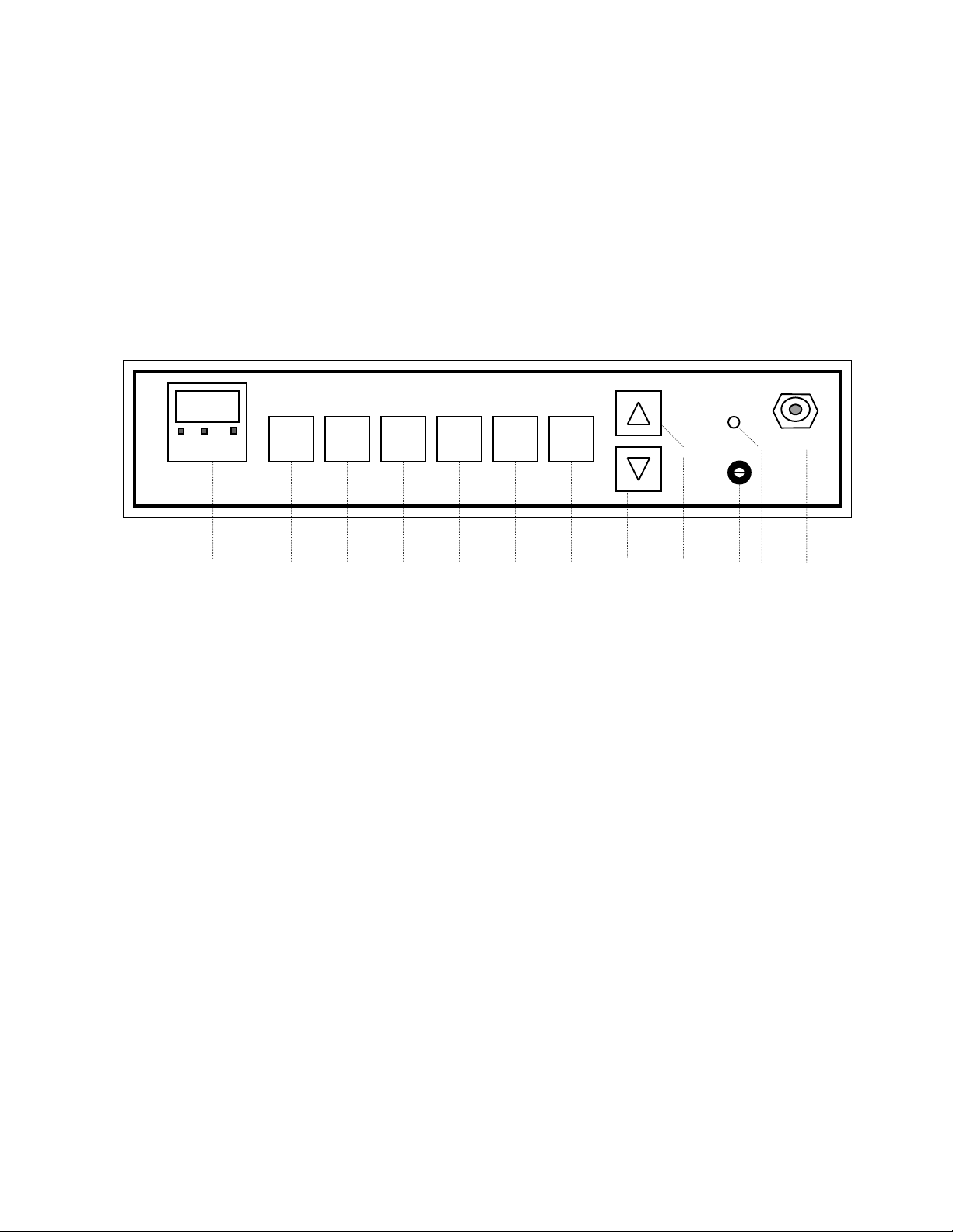
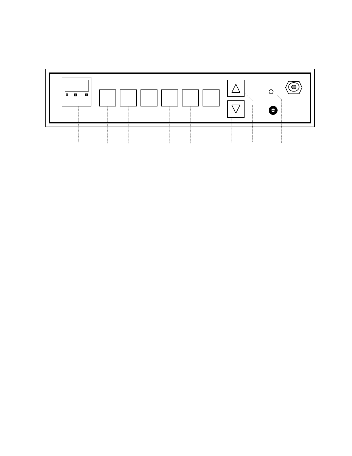
The control panel for all models has a series of command keys which
enables the user to enter set point values for temperature, carbon dioxide, door
heat and to calibrate the unit as required. LED readouts provide the user with
current status information regarding the foregoing parameters.
CONTROL PANEL:
ºC %CO2 HEAT HOLD HI LIMIT SAMPLE
1 23456789101112
FEATURES
SET CAL CO2 TEMP DOOR SCAN
1. LED READOUT: The LED displays current CO2 tension and temperature
in the Incubator and, in the set mode, displays the set point values
for these two parameters as well as door heat setting. It also enables the
user to enter values necessary to calibrate temperature and CO2.
Indicating lights and legends serve to identify which parameter is being
displayed.
2. SET COMMAND KEY: The SET key is the beginning point for and
initiates subsequent actions of the other keys on the control panel.
3. CAL COMMAND KEY: The CAL key permits calibration of temperature
and CO
used to change the readout to correspond with the readings obtained from
known standards of temperature or CO2 measurement. Both temperature
and CO
2 when in this command mode. The Up and Down arrow keys are
2 calibration use the zero point shift method.
FEATURES: (Con’t)
13
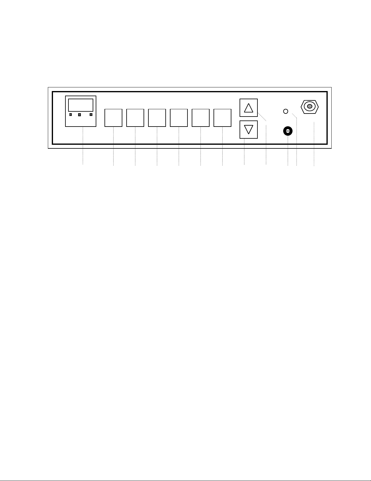
CONTROL PANEL: (Con’t)
SET CAL CO2 TEMP DOOR SCAN
ºC %CO2 HEAT HOLD HI LIMIT SAMPLE
1 23456789101112
4. CO2 COMMAND KEY: Pressing the SET key and then the CO2 key
allows the user with the Up and Down keys to enter the desired carbon
dioxide level in the Incubator.
• High and low limit alarm set points are factory set at ±1% above and
below the user-established set point. In the event CO2 exceeds the
indicated limits, an audible alarm will sound and indicating light
above the key will flash.
• Pressing any key will silence the alarm for a period of one hour. The
user should immediately investigate the reason for the alarm and
take steps to correct the problem. Note that the indicating light
continues to flash. If a problem is not solved the alarm resumes.
• By pressing the CAL (#3) and CO
calibrate CO2. The Up and Down arrow keys will change the readout
to correspond with the readings obtained from known standards of
CO2 measurement.
FEATURES: (Con’t)
2 (#4) keys sequentially users can
14

CONTROL PANEL: (Con’t)
SET CAL CO2 TEMP DOOR SCAN
ºC %CO2 HEAT HOLD HI LIMIT SAMPLE
1 23456789101112
5. TEMP COMMAND KEY: Pressing the SET key and then the TEMP
command key allows the user with the Up and Down arrow keys to
establish the desired set point temperature in the Incubator.
• High and low limit alarm set points are factory-set at ±1ºC. If the
temperature deviates from these limits, an audible, continuous alarm
will sound and the temperature lamp will flash.
• While pressing any key will silence the alarm for a one-hour period,
the user should immediately investigate the reason for the alarm and
take steps to correct the problem. Note that indicating light continues
to flash. If problem is no t corrected, the alarm will resume after one
hour has passed.
• By pressing the CAL (#3) and TEMP (#5) keys sequentially users
can calibrate temperature. The Up and Down arrow keys will change
the readout to correspond with the readings obtained from known
standards of temperature measurement.
NOTE: DECREASES IN TEMPERATURE AND CO2 DUE TO NORMAL DOOR OPENINGS ARE
TOLERATED WITHOUT INITIATI NG THE ALARMS.
FEATURES: (Con’t)
15
CONTROL PANEL: (Con’t)
SET CAL CO2 TEMP DOOR SCAN
ºC %CO2 HEAT HOLD HI LIMIT SAMPLE
1 23456789101112
6. DOOR HEAT COMMAND KEY:
• When the SET key is pressed followed by the DOOR-HEAT key, the
level of heat can be entered with the Up and Down keys as a
percentage value being applied to the inner glass door.
• A flashing DOOR-HEAT indicator light above the key indicates that
heat is being applied to the inner glass door.
• A good starting point for the door heat control is 35%; if fogging still
occurs, increase in 10% increments until fogging disappears.
7. SCAN/HOLD COMMAND KEY: Permits holding the value of a single
parameter for continued viewing or scans alternately between the values
of the two parameters on a 2-second interval.
8. DOWN-ARROW KEY: This key decreases numerical value of the
parameter which has been accessed.
9. UP-ARROW KEY: This key increases the numerical value of the
parameter that has been accessed.
NOTE: A 5 SECOND DELAY AFTER ANY FINAL ENTRY RESULTS IN AUTOMATIC ENTRY
OF THAT CHANGE.
FEATURES: (Con’t)
16
 Loading...