

Page 1
Operation manual
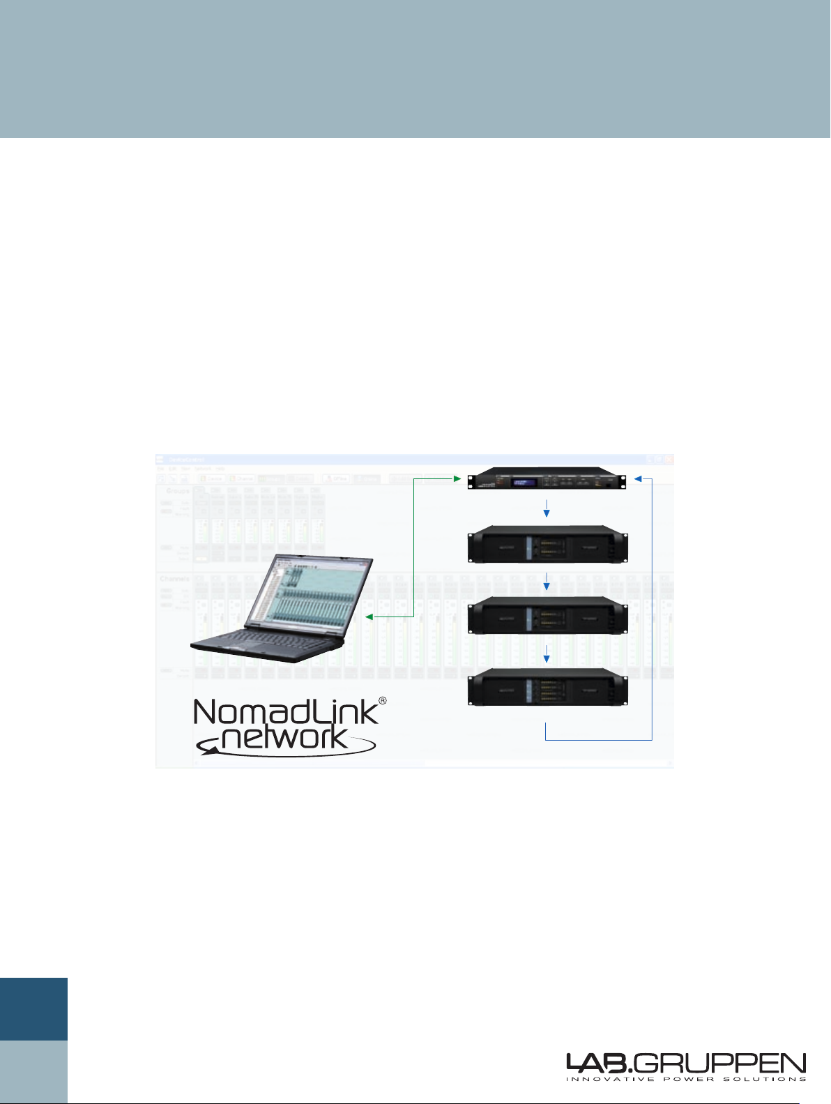
DeviceControl
NomadLink Network Control and Monitoring Software
Rev. 2.0.0
Item no. OM-DC
Page 2

2 DeviceControl Operation Manual
1 contents
1 CONTENTS .................................................................................................................................................2
2 DEVICECONTROL INTRODUCTION .........................................................................................................4
2.1 Overview .............................................................................................................................................4
2.2 New features in DeviceControl 2.0.0 ...................................................................................................4
3 INSTALLING THE DEVICECONTROL APPLICATION ...............................................................................5
3.1 Computer system requirements ..........................................................................................................5
3.2 Software installation ............................................................................................................................5
3.3 Software updates ................................................................................................................................5
3.4 Uninstalling DeviceControl ...................................................................................................................5
4 CONNECTING YOUR PC TO NOMADLINK ..............................................................................................6
4.1 Establishing a NomadLink Network .....................................................................................................7
4.2 Determining preferred connection type ...............................................................................................7
4.2.1 Peer-to-peer connection (using crossed RJ45 cable) ...............................................................7
4.2.2 LAN connection (wired via “straight” RJ45 cables or via wireless) .........................................7
4.3 Establishing a peer-to-peer connection ...............................................................................................7
4.3.1 Physical connection ..................................................................................................................7
4.4 Maximum cable lengths ......................................................................................................................7
4.5 TCP/IP setup ........................................................................................................................................8
4.6 Establishing a wired or wireless LAN connection ...............................................................................9
4.7 Multiple subnets without a DHCP server ............................................................................................9
5 QUICK GUIDE FOR BASIC FUNCTIONS .................................................................................................10
5.1 Uploading subnets .............................................................................................................................10
5.1.1 No subnets found fault ........................................................................................................... 11
5.2 Toolbars overview .............................................................................................................................. 12
5.3 Start Here ..........................................................................................................................................14
5.3.1 Basic operations .....................................................................................................................14
5.3.2 Lock mode ..............................................................................................................................14
5.3.3 Creating Channel Groups ........................................................................................................15
5.3.4 Creating Power Groups ..........................................................................................................15
5.3.5 Naming (or re-naming) Devices, Channels and Groups ..........................................................15
5.3.6 Saving the configuration file ...................................................................................................15
5.3.7 Opening a saved system configuration file ............................................................................16
5.3.8 Reconnect to a subnet ...........................................................................................................16
5.3.9 Establishing secure connections ............................................................................................16
5.3.10 Synchronization ......................................................................................................................16
5.3.11 Normal operation with devices matched and synchronized ...................................................17
6 REFERENCE SECTION .............................................................................................................................18
6.1 Secure Connections ...........................................................................................................................18
6.1.1 Enabling secure connections ..................................................................................................18
6.1.2 Set password ..........................................................................................................................18
6.1.3 Adding additional subnets to a secure connection .................................................................19
6.1.4 Disabling secure connections .................................................................................................19
6.1.5 Resetting passwords ..............................................................................................................20
6.1.6 Verify secure connection ........................................................................................................20
6.2 Lock Mode .........................................................................................................................................21
6.2.1 Overview ................................................................................................................................21
6.2.2 Selecting lock type .................................................................................................................21
6.2.3 Confirmation ...........................................................................................................................21
6.2.4 Password protection ...............................................................................................................21
Page 3

DeviceControl Operation Manual 3
contents 1
6.3 Offline and Online states ...................................................................................................................22
6.3.1 Selecting offline and Online states .........................................................................................22
6.3.2 Functions allowed in Offline and Online states ......................................................................22
6.4 Device View .......................................................................................................................................23
6.4.1 Overview ................................................................................................................................23
6.4.2 Device view columns .............................................................................................................23
6.4.3 Editing functions in Device View ............................................................................................24
6.4.4 Matching to the physical subnet .............................................................................................25
6.4.5 Device sorting ........................................................................................................................25
6.4.6 Disconnecting devices for drag-and-drop reassignment ........................................................25
6.5 Channel View .....................................................................................................................................26
6.5.1 Overview ................................................................................................................................26
6.5.2 Forming Channel Groups ........................................................................................................26
6.6 Group View ........................................................................................................................................27
6.6.1 Overview ................................................................................................................................27
6.6.2 Group View buttons and functions .........................................................................................28
6.6.3 Group View fault and warning indicators ................................................................................28
6.6.4 Channel fault and warnings ....................................................................................................28
6.6.5 Channel and subnet warning and fault icons ..........................................................................29
6.6.6 Level meters and clip LEDs ................................................................................................... 30
6.7 Power Groups View .......................................................................................................................... 30
6.7.1 O ver vi ew ............................................................................................................................... 30
6.7.2 The Groups pane ................................................................................................................... 30
6.7.3 The Configuration pane ......................................................................................................... 30
6.8 Details View .......................................................................................................................................31
6.8.1 Overview ................................................................................................................................31
6.8.2 Subnet details .........................................................................................................................31
6.8.3 Device details .........................................................................................................................32
6.9 Tree View .......................................................................................................................................... 35
6.9.1 Overview ............................................................................................................................... 35
6.9.2 Functionality .......................................................................................................................... 35
6.9.3 Drag and drop Channel Group assignment ............................................................................ 35
6.10 Settings dialog .................................................................................................................................. 36
6.10.1 General .................................................................................................................................. 36
6.10.2 Locks ..................................................................................................................................... 36
6.10.3 Security (secure connections) ............................................................................................... 36
6.10.4 Synchronization ..................................................................................................................... 36
Page 4

4 DeviceControl Operation Manual
2 Devicecontrol introDuction
2.1 Overview
DeviceControl is a powerful tool for monitoring and
controlling Lab.gruppen amplifiers equipped for use
with the NomadLink network, including all C Series
and FP+ Series models. To fully realize the power and
flexibility of this program, we suggest that you refer
to this manual during setup, and also keep it handy
for reference until you are fully familiar with system
configuration and all operating modes.
DeviceControl runs on a standard Windows PC
equipped with an Ethernet interface. Supported
operating systems are Windows 2000 and Windows
XP with Service Pack 2 (SP2). Working in conjunction
with the NomadLink Bridge & Network Controller
(NLB 60E), DeviceControl allows detailed monitoring
of amplifier parameters while controlling key functions
such as power on/off, mute and solo. Although it is
remarkably intuitive and easy to use, DeviceControl is
a powerful system management tool. DeviceControl
applications apply to systems of any size, from a few
channels in a small venue to literally thousands of
channels in the largest imaginable stadium or theme
park system.
2.2 New features in DeviceControl 2.0.0
Secure Connection restricts access to authorized
•
computer(s)
Power Groups allows grouping of selected
•
devices for sequential powering on and off with
a single button click
Flexible Synchronization mode uploads data from
•
the physical amplifiers to the configuration, or
downloads from configuration to amplifiers
New Settings dialog simplifies selection of
•
modes and preferences
“Select All” and “Deselect All” buttons speed •
uploading from subnets
User interface improvements, including check-•
boxes for Channel Group selection
This manual is structured to serve as both a setup
guide and a reference. The following two sections
(2 and 3) will guide you through installation of the
DeviceControl software program and setup of
Ethernet connections to one or more subgroups of
amplifiers, each group controlled by an NLB 60E (also
referred to as a “subnet” in following text). Section
4 is a Quick Guide for accessing basic control and
monitoring functions. Section 5 details all operating
modes, menu options, offline system configuration,
and match functions, along with the various warning
and fault indications.
Page 5
DeviceControl Operation Manual 5
instAllinG tHe Devicecontrol APPlicAtion 3
3.1 Computer system requirements
Operating system: Windows 2000 or Windows
XP(SP2)
Processor: Intel Pentium 4 or XP-compatible equivalent (Celeron M, Athlon etc.)
RAM: 512 MB minimum
Hard drive free space: 20 MB
Monitor: 800 x 600 24-bit color
Network: Ethernet 10/100 Mbit
Screen resolution is fixed at 96 DPI. Altering this
setting will impair the operation of DeviceControl
so is not advised.
3.2 Software installation
Install the application by running the DeviceControl_Installer-2.0.0.exe application. The latest version
is located on the Download Software page of our
website at www.labgruppen.com. Follow the instructions as shown in the installation wizard.
3.4 Uninstalling DeviceControl
Should you wish to uninstall the software for any
reason, simply locate the DeviceControl program
folder and select the Uninstall option.
The application installs all necessary components
needed to run DeviceControl. A shortcut for quick
access to DeviceControl will be placed on your
desktop.
3.3 Software updates
If you have a previous version of DeviceControl
already installed, the DeviceControl installer file will
automatically upgrade your software by overwriting
the older version.
If the software needs to be reinstalled for
any reason, it is best to always reinstall the
latest version (not a previous version) to
maintain full compatibility with any existing
configuration files or firmware versions. Lock Mode
and Secure Connection passwords will remain after
an update.
Page 6
6 DeviceControl Operation Manual
4 connectinG Your Pc to noMADlinK
Crossed RJ45 cable between NLB 60E
and PC. If NLB 60E is connected to switch
of HUB, use "straight" cable. PC can also be
connected on front-panel.
"Straight" RJ45 cables between
NLB 60E and amplifiers.
4.1 Establishing a Nomadlink
network
You must establish the NomadLink Network before
you connect the DeviceControl host computer. If you
have done so already, proceed to Section 4.2.
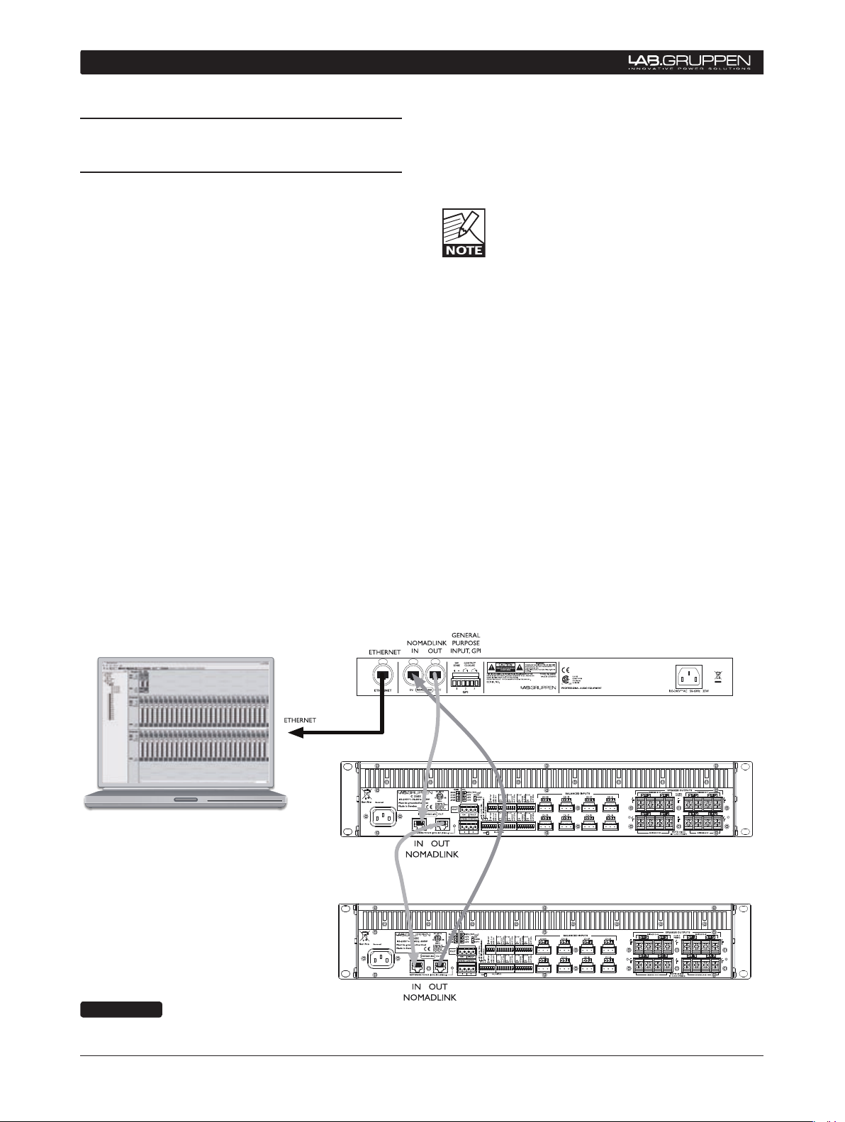
Conne cting the NLB 6 0E to La b.gru ppe n amplifiers i n
a NomadLink network is a simple and straightforward
procedure. All connections are made with standard
(“straight”) Ethernet-type cables equipped with RJ45
connectors. Cable grade should be Cat-5 or better.
The NLB 60E connects to the amplifiers through the
two rear panel ports labeled NOMADLINK IN and
OUT. Using a standard (“straight”) Ethernet cable,
connect the OUT por t on the NLB 60E to the IN p ort
on the first amplifier in the network. Next, connect
the OUT port of the first amplifier to the IN port of
the second amplifier. Continue to “daisy chain” the
am pli fiers, connecti ng the OUT por t to th e IN por t of
the next amplifier, until all amplifiers are connected.
Complete the network loop by connecting the OUT
port of the last amplifier to the IN port on the NLB
60E (Figure 4.1).
The OUT port of the NLB 60E must be connected
to the IN port of the first amplifier to allow the DeviceControl software to correctly identify devices
on the network.
IMPORTANT NOTE: Within restricted
cable distances, the NomadLink network
will function as a single-ended daisy chain
without closing the loop. (The loop is closed
by connecting the last amplifier’s OUT port back to
th e NL B 60Es IN por t). However, it is s trong ly rec ommended that the loop be completed: doing so provides
a redundant signal path and improves communication
speed on the network
Figure 4.1
Page 7
DeviceControl Operation Manual 7
connectinG Your Pc to noMADlinK 4
4.2 Determining preferred connection type
You may connect your DeviceControl host computer
to the NomadLink Network using either a direct
(peer-to-peer) connection, or via a LAN (Local
Area Network). A LAN requires inserting a router
or network switch, with or without wireless (WiFi)
capability. Either a peer-to-peer or a LAN connection
will work with a single NLB 60E (one subnet); a LAN
is normally required for connection to more than one
NLB 60E (multiple subnets).
4.2.1 Peer-to-peer connection (using crossed RJ45 cable)
In this configuration, a dedicated TCP/IP connection is
ma de d irectly to the NLB 6 0E using only an Ether net
cable. This type of connection may be preferable in
these applications:
Temporary connections for setup or maintenance
•
of an NLB 60E when functioning as a self-standing
unit; operation is via front panel or GPI
Permanent connections between one NLB 60E •
and a computer dedicated to the DeviceControl
application.
vices, a LAN connection avoids any need to manually
reset the TCP/IP configuration when switching from
DeviceControl to another application. If the network
router offers DHCP assignment (now common even
in inexpensive models), then the NLB 60E can be
set to automatically accept a network address from
the router.
A separate, third-party network device must
be accommodated in the system to create
a LAN connection. This could raise reli-
ability issues, particularly in touring applications. Any network devices should be chosen with
this consideration in mind.
4.3 Establishing a peer-to-peer
connection
4.3.1 Physical connection
Connect the PC to the NLB 60E using an Ethernet
cable. A crossed cable should be used for peerto-peer connections; however, many newer PCs
may allow peer-to-peer connection using a standard
(“straight”) Ethernet cable (Figure 3.1).
In this configuration, a dedicated TCP/IP connection
is made directly to the NLB 60E. A peer-to-peer
connection ensures that no other network devices are
inserted between the computer and the NLB 60E.
If a dedicated connection is established, no
other network connections will be available
through the assigned Ethernet port. How-
ever, if the computer also has multiple
Ethernet ports or a wireless LAN connection, these
remain available for other uses such as Internet access.
4.2.2 LAN connection (wired via “straight”
RJ45 cables or via wireless)
A LAN connection is required if the system configuration requires more than one subnet, as each subnet
is controlled by a dedicated NLB 60E.
A LAN connection may be preferred in some applications even if only one subnet is required. If the
host computer is needed for Internet access via the
Ethernet port, or for controlling other networked de-
Two Ethernet ports are provided on the NLB 60E:
one on the front panel and one on the rear panel (the
front panel port is primarily for temporary setup and
service use). Both ports are active but only one can
be used at a time.
4.4 Maximum cable lengths
Maximum cable length allowed between the DeviceControl host PC and the NLB 60E (or LAN network
device) conforms to standard Ethernet specification
of 100 meters.
The maximum cable length in between any interconnected NLB 60E and an amplifier may not exceed
300 meters. Total cable length for links in between
all amplifiers in one subnet may not exceed 100
meters.
As a result, in a non-closed-loop daisy-chained subnet,
the total maximum cable length is 400 meters (300
+ 100), and in a closed loop subnet the maximum
cable length is 700 meters (300 + 300 + 100).
Page 8
8 DeviceControl Operation Manual
4 connectinG Your Pc to noMADlinK
4.5 TCP/IP setup
To establish direct (peer-to-peer) communication
between the DeviceControl host PC and the NLB
60E, you first must set the TCP/IP address in your
computer.
The NLB 60E has following default address:
IP: 192.168.1.166
Subnet mask: 255.255.255.0
Gateway: 0.0.0.0
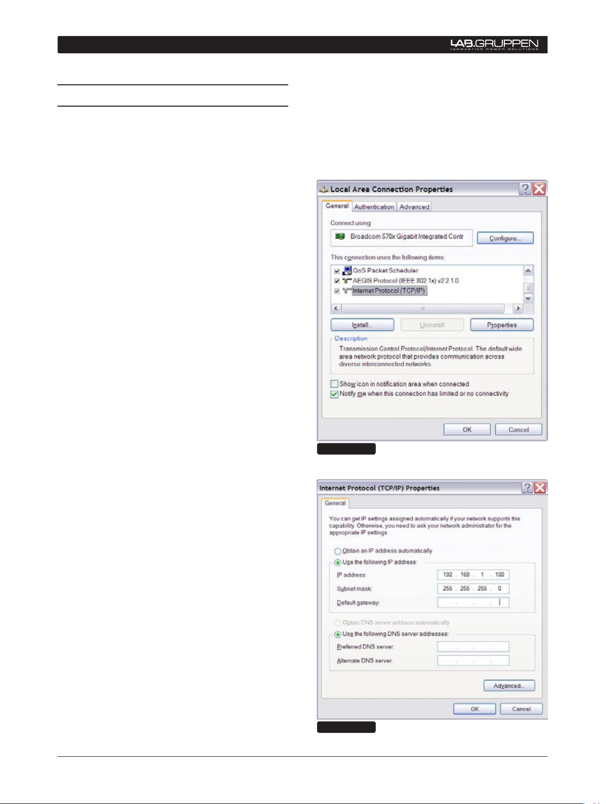
The PC must be set manually to a compatible address, for example:
IP: 192.168.1.100
Subnet mask: 255.255.255.0
Gateway: 0.0.0.0
To establish a connection, use the following procedure:
Click on OK. The address is now set. You can 6.
verify that your settings are correct by doubleclicking on “Local Area Connection” and
selecting the Support tab.
The PC is now ready to connect to the NLB 7.
60E. Refer to instructions in Section 5 .
XP Home - Open the Start menu in the lower left 1.
corner. Select “Connect to” and then “Show all
connections”
XP Professional - Open the Start menu in
the lower left corner. Select “Settings”,
“Control Panel” and then (if in Classic view)
“Network Connections”. If the Control Panel
is in Category view choose “Network and
Internet Connections” and then “Network
Connections.”
Select “Local Area Connection”. Select 2.
“Properties” from the File menu or by rightclicking on the selected icon. In the pop-up
window, select (highlight) “Internet Protocol
(TCP/IP)”. Click on the “Properties” button to
view TCP/IP Properties (Figure 4.2).
Select “Use the following IP address” and enter 3.
a desired address. (Figure 4.3).
Click in Subnet Mask. Keep the default 4.
255.255.255.0 value.
Figure 4.2
Leave Default Gateway open. Do not enter any 5.
values.
Figure 4.3
Page 9

DeviceControl Operation Manual 9
4.6 Establishing a wired or wire-
less LAN connection
It is recommended that you make your LAN connections using a network device (hub, switch or router)
that includes a DHCP server function. This feature
greatly simplifies network configuration. For use with
non-DHCP devices, see Section 4.5.
Connect the host computer and one or more NLB
60Es to the network device using standard Ethernet
cables.
To o btain an IP a ddres s automatic ally, each NLB 6 0E
must be set to “DHCP On” This setting is accessed
via the front panel navigation features of the NLB 60E
under the “Bridge Info” section. Refer to the NLB
60E Operation Manual for more details.
The NLB 60E automatically re-boots after changing the setting. The front panel display then shows
automatic acquisition of an IP address.
connectinG Your Pc to noMADlinK 4
In most cases, no further configuration of the PC will
be necessary. Because the default setting in Windows is to “Obtain an IP address automatically”, the
network connection will be established by the DHCP
server. However, if the PC has been previously set
to obtain a specific address, you may need to access
the “Internet Protocol (TCP/IP) Properties” window
and select the “Obtain an IP address automatically”
option (Figure 4.3).
4.7 Multiple subnets without a
DHCP server
It is possible to create networks with multiple subnets
using either a computer equipped with multiple
Ethernet cards, or with network devices requiring
manual IP address setting. In these applications,
each connection must be manually set with a TCP/
IP address with the last three digits in the range of 1
to 255. Such applications are rare and therefore are
not detailed here. However, standard procedures for
TCP/IP networks apply.
Page 10
10 DeviceControl Operation Manual
5 QuicK GuiDe for BAsic functions
The following section provides the basic information
required to use DeviceControl in most common applications. Instructions are provided for uploading
amplifier data from physical subnets, performing
basic operations, monitoring faults and warnings,
and creating groups of amplifiers (for power on/off)
as well as grouping amplifier channels.
Make sure you have completed the steps in Section
4, and you are ready to run the application; Double
click the DeviceControl shortcut on your Desktop or
select DeviceControl in the Start menu. On opening,
DeviceControl displays the Quick Start menu (Figure
5.1).
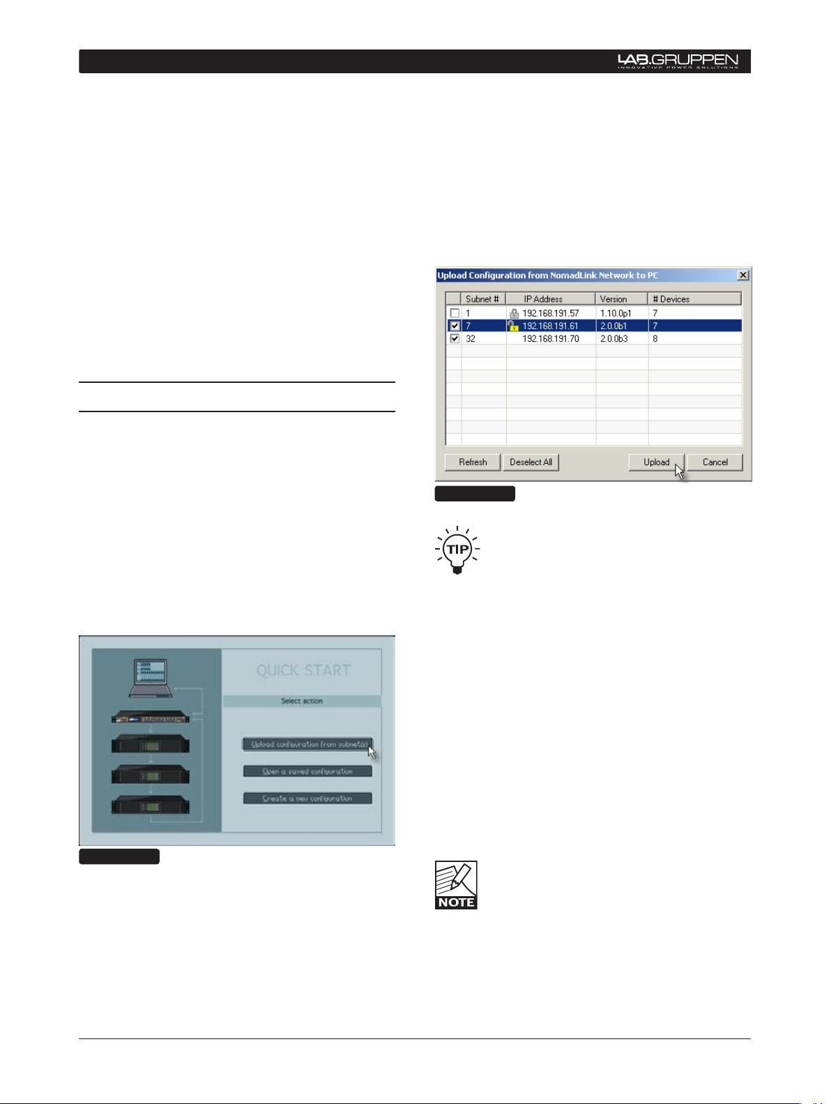
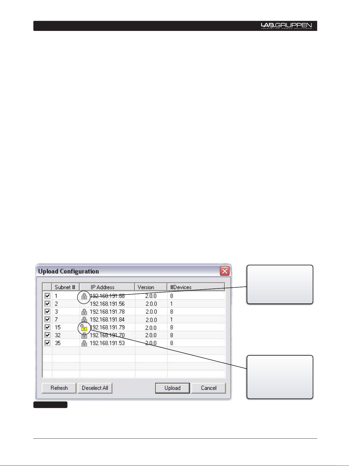
5.1 Uploading Subnet(s)
The Quick Start window (Figure 5.1) allows selection
of three different DeviceControl startup alternatives.
Available choices are:
1) Upload configuration from subnet(s)
2) Open a saved configuration
3) Create a new configuration
If you are working offline (no physical subnet is connected), select the second or third choice to access
offline editing functions. See Section 6.3.
The pop up window (Figure 5.2) displays the detected
NLB 60Es along with their subnet numbers, secure
connection status, IP Address, NLB 60E firmware
version and the number of devices (amplifiers) connected to the subnet.
Select the subnet(s) you want to upload and click on
the Upload button.
Figure 5.2
All detected subnets are selected in the
pop-up to be uploaded by default. Unselect
subnets by clicking corresponding check-
boxes. Or, you may use the “Deselect All”
button and check the checkboxes for the subnets
you wish to upload.
Figure 5.1
When a physical subnet is connected, you can automatically acquire data directly from the amplifiers
by selecting “Upload configuration from subnet(s)”.
DeviceControl interrogates the NomadLink network
interface, locating available subnets and listing them
in a pop-up window.
When Upload is clicked, DeviceControl interrogates
the subnets. In the default synchronization mode, it
uploads information from the subnets and automatically generates lists and default groups for the various
display views.
Clicking on the Refresh button re-interrogates the
network after initial uploading. Use Refresh to update subnet information when changes are made to
connected subnets, or when network connection is
temporarily lost due to inadvertent physical disconnection
As many as 60 subnets can be detected
and uploaded simultaneously into Device-
Control on one host computer.
Page 11
DeviceControl Operation Manual 11
QuicK GuiDe for BAsic functions 5
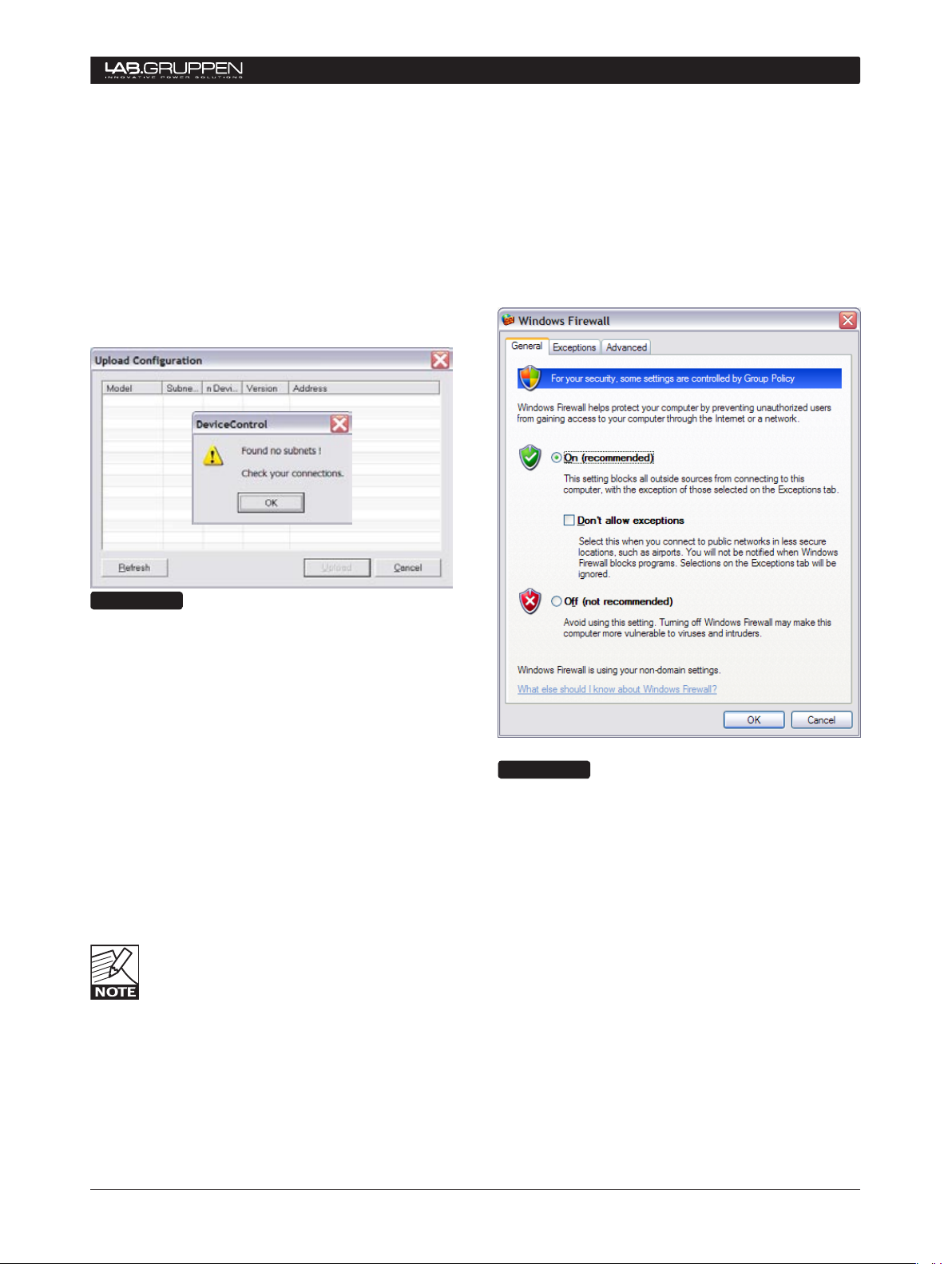
5.1.1 No Subnets found fault
If DeviceControl does not locate any available NLB
60E on the network, a pop-up window appears
(Figure 5.3).
If you are certain that subnets have been connected,
this could indicate a problem with a physical connection, the network configuration or the Windows
Firewall,
Figure 5.3
DeviceControl by accessing the Windows Security
Center in the Control Panel (Figure 5.4).
Set the Firewall to “On (recommended)” and click
on Windows Firewall in Manage Security Settings.
Click on the “Exceptions” tab and confirm that
DeviceControl Network Application is selected as
an exception.
Check Connections and Configurations
Check your cable connections and your TCP/IP settings at both the PC and NLB 60E.
Check Windows Firewall
If this fault appears the first time you attempt to
upload subnets, and your PC has Windows XP with
SP2, your connection probably has been blocked by
the Windows Firewall.
When you first click on “Upload configuration”, a
Windows pop-up asks whether you want to continue blocking or allow network communication by
DeviceControl. Click on Unblock.
In some cases this pop-up window may be
hi dden behind the main w indow. However,
you will see a “Windows Security Alert”
below in the sy stem tray. Mi nimize the main
window or click on the Windows Security Alert in
the system tray to access the pop-up and click on
Unblock.
Figure 5.4
You can check to see if Windows Firewall is blocking
Page 12
12 DeviceControl Operation Manual
5 QuicK GuiDe for BAsic functions
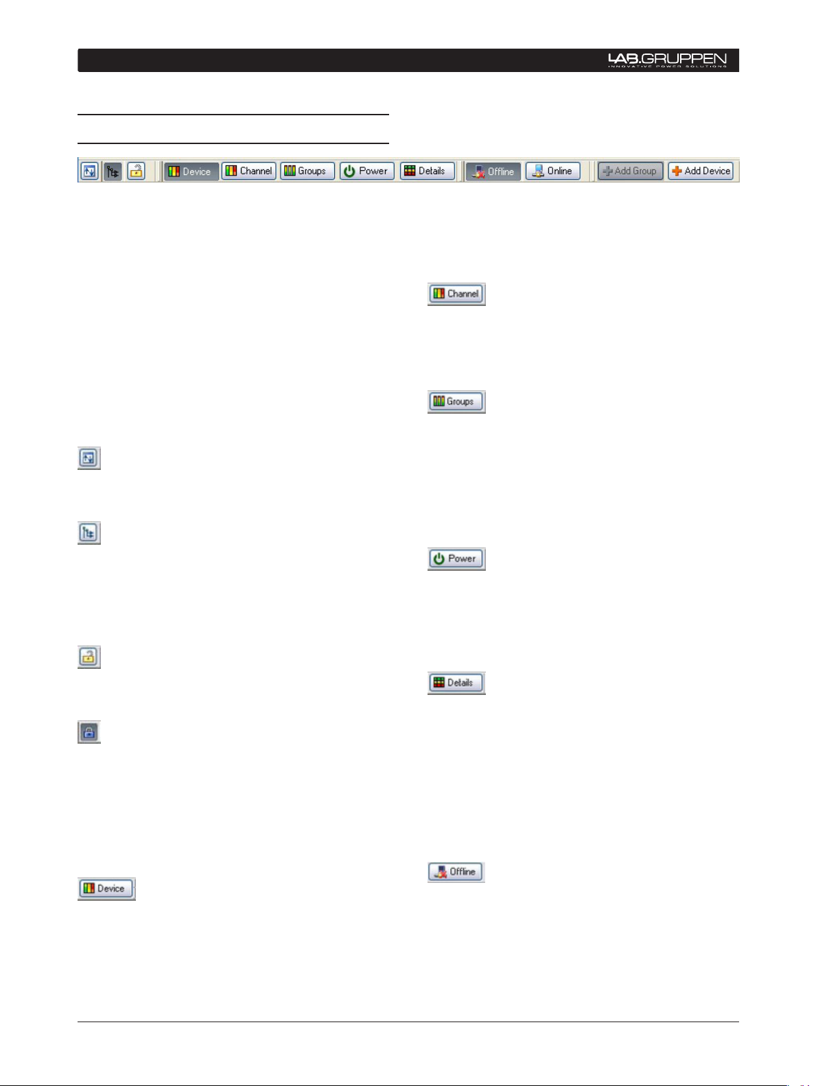
5.2 Toolbars overview
DeviceControl is organized around a set of views
accessible by selecting buttons on the main toolbar.
The different views access various configuration,
operation, and monitoring functions. More detailed
information is given in the Reference Section 6.
(Physical) displays the detected devices in the
subnets. Center “link” indicator between left and
right shows Match status between configured and
physical devices.
The Toolbar is grouped into four segments; Toolbar,
Select View, Mode and Edit bar. Each segment may
be independently repositioned by clicking on and
dragging to the respective end bars.
Toolbar segment:
Full screen: Toggles between full screen and reduced
screen view.
Tree View: The Tree View is open by default on the
left side of the screen when opening DeviceControl.
This view shows the current network configuration
(either as uploaded or created offline), including all
subnets and groups.
Lock: Engages operational or configuration lock
modes in DeviceControl
Blue icon indicates configuration lock only; yellow is
both configuration and operational lock. Lock type
can be set in the Settings dialog in the File menu.
For detailed instruction see Section 6.2.
Channel View: The Channel View shows all configured channels as derived from the Device list. In
this view you may add or delete Channel Groups, and
assign channels to new or existing groups.
Groups View: The Groups View is generated from
the selections made in the Channel list. The All and
Subnet Groups are automatically generated during
upload from the subnet(s) and cannot be modified.
The Groups View is the primary screen for monitoring
status, faults and warnings, as well as for controlling
mute and solo functions.
Power View: The Power Vi ew dis plays all devices in
the system and allows grouping of selected devices
for powering on and off as a group with a single
button click. The entire system and all connected
subnets are default Power Groups.
Details View: The Details View shows parameter
details for the selected channel or device (amplifier
or NLB 60E), including DIP-switch settings, performance indicators such as level and temperature,
and a sensitivity calculator for power and sensitivity
calculation dependent on configured settings.
Select view bar:
Device View: The Device View shows the list of
devices (amplifiers). The left side of the list displays
the virtual configured devices, with the power on/
off switch indicated for each device. The right side
Mode bar:
Offline: When not connected to a physical subnet,
editing of an offline configuration is possible. You
may add devices, add groups, rename channels and
devices, and set configured DIP-switches.
Page 13

DeviceControl Operation Manual 13
Online: When a configuration is created offline
and subsequent connection to a physical subnet is
required, selecting Online interrogates the network
and uploads amplifier information. The type and
position of available devices are compared to the
configuration, and an indication of the “Match” status
can be seen in the Device list view. DeviceControl
must be in the Online state to perform operating
functions (on/off, mute, solo) and to monitor amplifier
status.
Edit bar:
Add Group: Availa ble Offline or O nline when access-
ing the Channel or Power View. Clicking this button
adds groups to a subnet configuration.
QuicK GuiDe for BAsic functions 5
Add Device: Available Offline or Online when accessing the Device View. Clicking this button adds
devices to a subnet configuration.
Page 14

14 DeviceControl Operation Manual
5 QuicK GuiDe for BAsic functions
5.3 Start Here
The logical navigation structure and user-friendly
graphical interface of DeviceControl make all operations intuitive and easy to learn. Nevertheless, it is
suggested that you configure a physical NomadLink
“learning system” in a non-critical environment to
become thoroughly familiar with common operating
and editing features.
Some operations outlined in this section
can be performed in more than one view.
To simplify the Quick Guide, only the most
commo nly us ed v iew is given here. Se e the
Reference section for each view for more details.
5.3.1 Basic operations
The following three operations are available only
when DeviceControl is in the Online state.
Power on/off
Amplifiers may be powered on and off in groups
using the On and Off buttons in the upper pane of
the Power View. For information on creating Power
Groups, see Section 5.3.4.
Each NLB 60E may be programmed for
sequential power On for all amplifiers in the
subnet. Using the power On button for a
subnet in Power Groups will activate the
pre-programmed sequential power On. Also, if two
or more amplifiers in a Power Group are in the same
subnet with an NLB 60E set for sequential power
On, the amplifiers will power up with the programmed
delay interval.
Individual amplifiers may be powered on or off using
the buttons in the lower pane. Click the On button
to turn power on or off. The button illuminates to
indicate the device is powered up. Power on/off
functions for individual amplifiers are also accessible
in the Device View.
Mute
Mute functions are most easily accessible in the
Group View. Click on the Mute button at the bottom
of the graphical module as appropriate. You may
select All (all channels on all subnets), Subnet (channels in the selected subnet only), Group (channels in
selected group), or any individual channel. The button
illuminates to indicate mute status of the selected
channel(s).
Solo
Solo functions are most easily accessed in the Group
View. You may solo a subnet, a group, or an individual
channel by clicking on the appropriate Solo button
at the top of the graphical module. The yellow Solo
button illuminates to indicate solo status of selected
channel(s). All other channels show a mute indication.
Mute takes precedence over Solo. A channel that has been muted, either locally or
as part of a group, cannot be soloed until it
has been un-muted.
IMPORTANT NOTE: A Mute or Solo command for a subnet will affect all devices
connected to the subnet, including those
devices not in the current configuration or
shown as “Unknown”.
5.3.2 Lock mode
You may lock DeviceControl to prevent inadvertent
changes or unauthorized use. To lock DeviceControl,
click on the Lock icon in the toolbar. You may select
either Configuration or Operation lock modes by
clicking on the Locks tab of the Settings dialog,
accessible from the File menu.
Configuration lock prohibits changes to current •
and saved amplifier configurations. Operational
changes (power on/off, solo, mute) are permitted.
Operation lock blocks access to operating
•
functions (power on/off, solo, mute) as well as
prohibiting most changes to configuration. This
is essentially a “monitor only” mode. Refer to
Section 6.2.1 for more information.
You may block access to the Unlock mode by requiring a password. For details on setting and changing
passwords, see 6.2.4.
DeviceControl can be shut down without
exiting Lock mode, but it will restart ONLY
with the same configuration and state (Offline or Online) as before exiting.
Be certain that you know the correct current
password before locking DeviceControl with
Password lock engaged. If you are unable to
Page 15

DeviceControl Operation Manual 15
QuicK GuiDe for BAsic functions 5
unlock Operations lock, you will be unable to access
amplifier operating functions.
5.3.3 Creating Channel Groups
DeviceCo ntrol of fers a numbe r of features for Online
and Offline editing of amplifier configurations. For
many users, the most powerful editing feature will
be creating Channel Groups. You may assign any
channel from any device to a specific group. Channel
grouping is particularly useful when channels from
several devices are assigned to the same function
in the system, such as supplying power to the HF
drivers in a line array.
To create Channel Groups, click on the Channel View
button in the Toolbar. Groups may be created and
edited in either the Offline or Online state.
To add a new group, click the “Add Group” button.
Select the channels to be added to the new group
by clicking in the box to the right of the device corresponding to that channel. You may assign the same
channel to more than one group.
delete (delete key). Similarly, you may right click on
a device in a group to rename it or delete it, or use
the keyboard commands.
Also, devices may be added to a Power Group using
the drag and drop functionality in Tree View. See
Section 6.9.
Group power on/off function is discussed in Section
5.3.1.
5.3.5 Naming (or renaming) Devices, Channels and Groups
Device s - Yo u may ren ame devices to indicate fu nc-
tion or physical location, e.g. “left rack 2”. To rename
a device, choose Device View and select the device
and choose Rename from the Edit View. Alternatively,
you may use a slow left click, right click and choose
Rename, or use the F2 key. Enter the new name for
the device.
Channels – Channels may be renamed in the Channels View using the same procedures given above.
To access operating functions or status indications
for a group, select the Groups View. All groups and
subnets show in this view. All operations (mute, solo)
selected on the group module will affect all channels
in the group. Also, any fault or warning indications
affecting a channel in the group will be indicated for
the group as well. For detailed information on fault
and warning indications, see Section 6.6.4.
5.3.4 Creating Power Groups
To create Power Groups, click on the Power button
in the Toolbar. If no prior groups have been created,
only the default System and Subnet(s) groups will
show in the top pane. All devices (amplifiers) in the
current configuration will be shown in the lower pane
(as the System group is marked as default).
To create a new group, click on the Add Group button
in the Too lbar. In the lower p ane, c lick c orres ponding
checkboxes to assign devices to the group. Uncheck
checkboxes to remove devices from the group.
You may rename, delete, or clear Power Groups by
right-clicking on a group (either in Tree View or the
top pane of the Power view) and select the desired
action from the pop-up menu. Alternatively, you may
use the keyboard commands for rename (F2) and
Groups - After creating Channel or Power Groups,
you can rename the group to indicate the function
or location of the assigned groups, e.g. “Left HF”.
To rename a group, choose Channel or Power View
as appropriate. Place the cursor over the group to be
renamed, right-click and select “Rename”.
Tree Vie w - Renaming functions are also accessible
in the Tree View. See Section 6.9.2.
For Channel Groups, the new name must
be limited to six or seven characters to fit
in the “label space” on the Group module
graphic in Group View.
You may use Copy and Paste functions in
the Edit menu to replace the default name
with a “template” name (e.g. “Stage L, rack
X, amp X”). Then simply change the num-
bers as needed for each device or channel.
5.3.6 Saving the configuration file
You may save your configuration as a DeviceControl
file by selecting Save or Save As… from the File
menu. Also, a prompt window appears when you
close DeviceControl asking if you wish to save the
file, or any file changes.
Page 16

16 DeviceControl Operation Manual
5 QuicK GuiDe for BAsic functions
Your saved file stores all data that was uploaded from
th e physic al subnet as well as any cha nges you have
made, including renaming of devices or groups.
5.3.7 Opening a saved system configuration
file
To open a saved configuration, choose the “Open
saved configuration” option when first booting DeviceControl. When DeviceControl is running, choose
Open from the File menu.
To match your saved configuration to a physical
network, click the Online button. DeviceControl will
interrogate the network and attempt to match your
configuration to any connected physical network.
Devices that match will show the green Link icon . For
devices that show match faults, see Section 6.4.2.
5.3.8 Reconnecting to a subnet
If connection to a subnet is lost (e.g. due to accidental
disconnection of network cable), a Reconnect dialog
window appears. Click on Reconnect to re-establish
connection. If you inadvertently click Cancel, you
may reopen the dialog window by right-clicking on
the actual subnet in Tree View and selecting Reconnect.
changes will be “pushed” to amplifiers on the
subnet.
Download configuration from PC to
•
NomadLink network – With this option, any
changes to operating states (power, mute, solo)
made in the configuration while Offline will be
changed in the physical amplifiers when going
Online.
The first option (upload physical device state
to configuration) is the preferred “safe”
mode during system operation. It will not
allow any inadvertent changes to the con-
figuration to be activated in the physical devices.
To select synchronization option
Choose the Settings dialog from the File menu and
click on the Synchronization tab. Select a Default
Direction.
5.3.9 Establishing Secure Connections
You may establish a Secure Connection between
DeviceControl and one or more subnets. The Secure
Connection feature allows only an authorized computer with a matching password setting to access
the subnet(s). For details on setting up a Secure
Connection, see Section 5.1.
5.3.10 Synchronization
Each time DeviceControl goes from the Offline state
to the Online state, it interrogates the network and
synchronizes the current configuration file with any
physical amplifiers on the network. You may choose
from two synchronization options:
Upload configuration from NomadLink net-•
wo rk t o PC – With this option, the current active
state of the physical amplifier(s) is uploaded to
DeviceControl. The current Power On/Off, Mute,
and Solo states of the amplifiers will be shown in
DeviceControl. If the configured state is different
(e.g. power off instead of on) from the physical
device state, it will be changed in DeviceControl
to the current state of the physical device. No
Figure 5.5
A checkbox in the Settings dialog window, allows
selection of a confirmation dialog every time transition to Online occurs.
If this checkbox is checked a confirmation dialog
(Figure 5.5) appears every time a transition occurs
to Online.
It shows the selected synchronization option and
requires confirmation before the Online transition
takes effect. You may change the synchronization
option in the confirmation dialog, and also select a
“Do not show this dialog again” option.
Configured DIP-switch settings are not
changed when uploading from physical
amplifiers to a saved configuration. This
prevents any unintended changes to the
Page 17

DeviceControl Operation Manual 17
configuration. With either synchronization direction
(uploading from the physical am pli fiers o r downloa d ing from a configuration), both configured and
physical DIP-switch settings are compared. Any
mismatches are indicated as faults or warnings. See
section 6.4.2.
5.3.11 Normal operation with devices matched and synchronized
By following the above Quick Guide instructions, you
will be able to upload data from the network, create
groups, name groups, rename devices, and save a
configuration file. Under normal operating conditions,
all devices in Device View will show a green “Match”
indicator and a green “Status” indicator when you
re-open the file and connect to the network. Data
uploaded from the network will match the physical
configuration by definition; a mismatched state will
occur only if a physical change is made after uploading, such as changing a DIP-switch setting. No further
manual data entry is required using this method.
QuicK GuiDe for BAsic functions 5
For more detailed information, please consult the following Reference section. This additional information
will help you recognize and troubleshoot anomalous
conditions. It also gives more detailed instructions on
how to create and edit new configuration files “from
scratch” in the Offline state.
Page 18

18 DeviceControl Operation Manual
6 reference section
6.1 Secure Connections
The NLB 60E(s), connected to a NomadLink network,
can be connected to only one PC running DeviceControl. If the preferred or authorized computer is
not connected, any computer with DeviceControl
installed may access the NomadLink network as
long as secure connection functionality is inactive.
A secure connection restricts network access to a
DeviceControl installation with a password setting
that matches the password in the NLB 60E.
A secure connection may be preferred in two
situations. First, a secure connection will prevent
unauthorized access to the NomadLink network:
only a DeviceControl application with a matching
password will be able to connect to the network.
Also, secure connections can simplify operation
and monitoring of two or more completely separate
NomadLink systems operating over the same LAN.
Several host computers can use the same network,
with each DeviceControl application accessing only
those NLB 60Es programmed with respective matching passwords.
appears. Press OK.
Press Select and continue pressing until Security 2.
appears. Press OK. Press OK for Secure Conn.
After secure connection is enabled in the
NLB 60Es, it is important to immediately
enable secure connection in the DeviceControl application. The connection is not
secure until both steps are completed.
6.1.2 Set password
From the main window, select File menu and 1.
choose Settings.
Click on the Security tab.2.
Check the “Enable Secure Connection” (box 3.
Figure 6.1).
6.1.1 Enabling secure connections
Secure connection is available in DeviceControl version 2.0.0 and above, and with NLB 60E firmware
version 2.0.0 and above. Both are required. Secure
connection is disabled as default.
Enabling a secure connection is a two-step process.
First, the secure connection option must be enabled
manuall y on each NBL 60 E us ing th e front p anel key pad. Then a password must be set in DeviceControl
for both the host computer and all NLB 60Es with
secure connection enabled.
Once a secure connection is established in
DeviceControl, the secure connection will
be retained automatically with future software upgrades.
To enable secure connection,
repeat the steps below for all NLB 60Es in the system. DeviceControl must be offline to allow access
to front panel functions of the NLB 60E.
Press the Select key on the NLB 60E and 1.
continue pressing until the Configuration menu
Figure 6.1
Fill in a password in the “New Password” and 4.
“Confirm New Password” fields (Figure 6.2).
Press “Set”.
A new pop up appears “Set NLB 60Es 5.
password?” Click on “Yes”.
The “Set NLB 60E Password” dialog appears.6.
Leave “Old Password” field empty. (No 7.
password has yet been set in the NLB 60E).
Page 19

DeviceControl Operation Manual 19
Figure 6.2
Fill in “New Password” and “Confirm 8.
Password” with the same password set in
step 4. These passwords must be identical to
establish connection between DeviceControl
and NLB 60Es.
reference section 6
between DeviceControl and the NLB 60Es.
Verify that all added subnets are visible. c.
Press “Deselect All” and select the new
(added) subnets only.
Press “Set”.d.
8. Press “OK” in the Settings dialog. Secure
connection is now enabled in the additional
NLB 60Es.
You can verify that a secure connection has
been enabled by checking the NLB 60E
information log via the front panel menu
and display. Refer to the NLB 60E Operation
Manual for more information.
6.1.4 Disabling secure connections
Use this procedure if you no longer wish to have a
secure connection to the NomadLink network.
Verify that all NLB 60Es are selected. 9.
Press Set.10.
Press OK in the Settings dialog. The secure 11.
connection is enabled.
6.1.3 Adding additional subnets to a secure connection
Additional subnets may be added to an existing
secure connection as follows:
Enable the secure connection physically in the 1.
additional NLB 60E as described in 6.1.1.
Start DeviceControl2.
Choose “Create a new configuration” in the 3.
Quick Start menu.
From the main window, select Settings from 4.
the File menu.
Click on the Security tab.5.
Click on “Change authentication password” for 6.
NLB 60E
The “Change NLB 60E Password” dialog pops 7.
up.
Leave “Old Password” field empty. (No a.
password has yet been set in the newly
added NLB 60Es).
“New Password” and “Confirm Password” b.
are filled in with the same password set
in step 8 in 6.1.2 above. These passwords
need to be the same to establish connection
Disabling secure connection in the NLB 60E
The following steps must be repeated for each NLB
60E in the system.
Press the Select key on the NLB 60E front 1.
panel until the Configuration menu appears in
the display. Press “OK”.
Press Select until Security menu appears. Press 2.
“OK”.
Press “OK” for “Secure Conn.”.3.
Press on Adjust/Set until “Disable” appears. 4.
Press “OK” to confirm.
The previously set password in the NLB
60E is reset (deleted) when the secure
connection is disabled. A new password
m us t be s et in th e N LB 6 0 E when re - enablin g
a secure connection.
Disabling secure connection in DeviceControl
Start DeviceControl1.
Choose “Create a new configuration” in the 2.
Quick Start menu.
Select “File” and then “Settings…” from the 3.
menu bar.
Click on the Security tab.4.
Uncheck the “Enable Secure Connection” box.5.
Type password in the “Disable secure 6.
connection” dialog.
Upon completing step 6 above, the password is reset (deleted). A new password
Page 20
20 DeviceControl Operation Manual
6 reference section
Indicates that secure
connection is enabled and
that the password is NOT
set in this NLB 60E. This is
not a secure connection!
Indicates that secure
connection is enabled in
this NLB 60E
must be entered in this DeviceControl installation
when re-enabling a secure connection.
6.1.5 Resetting passwords
Use the procedure below if you want to maintain a
secure connection, but change the password.
Resetting the password in the NLB 60E
Repeat these steps for all NLB 60Es in the system:
Press the Select key on the NLB 60E front panel 1.
until “Configuration” appears on the display.
Press “OK”.
Press Select until “Security” appears. Press 2.
“OK”.
Press on Adjust/Set until “Reset Password?” 3.
appears. Press “OK” to confirm.
Set new password following the procedure in 4.
6.1.2 above.
Resetting the password in DeviceControl
The password in DeviceControl is deleted (disabled)
when Secure Connection is disabled by the procedure
described above. Authorization with the old (existing)
password is required before a new password can
be entered.
The password also is reset when DeviceControl is
uninstalled and reinstalled. Entry of the old password
is not required. However, depending on the Windows
configuration, uninstalling may require authorization
from the system administrator.
6.1.6 Verify Secure Connection
To verify the status of secure connection on the NLB
60Es the easiest way is to look at the upload dialog
(Figure 6.3).
Start DeviceControl1.
Choose “Upload configuration from network” 2.
in Quick Start menu.
Verify the information in the “Upload 3.
Configuration” dialog according to information
below
This information is also available in the “Set NLB
60E password” and “Change NLB 60E password”
dialogs.
Figure 6.3
Page 21

DeviceControl Operation Manual 21
reference section 6
6.2 Lock Mode
6.2.1 Overview
DeviceControl functions may be locked to prevent
unauthorized or inadvertent changes to either the
currently loaded configuration or to the operating
status of amplifiers on the network. Two different
Lock Modes are provided:
Lock Configuration (blue icon) – No changes to •
the currently loaded configuration are allowed.
Operate functions (power on/off, solo and mute)
remain enabled when DeviceControl is Online.
Lock Operations and Configuration (yellow
•
icon) – DeviceControl essentially functions in
a “monitor mode”. All status, warning and fault
indications remain available, but no changes are
allowed to the configuration or to any operational
function.
6.2.2 Selecting Lock Type
To select the desired Lock Type, open the Settings
dialog in the File menu and choose the Locks tab.
Select either Operations or Configuration (Figure
6.4).
6.2.3 Confirmation
A check box on the Locks tab of the Settings dialog
allows you to select a confirmation of the Lock Type
whenever the DeviceControl application is locked. If
checked, the Confirm Lock Type dialog appears each
time the Lock function is initiated (Figure 5.5).
Figure 6.5
DeviceControl can be shut down without
exiting Lock Mode. However, it will restart
ONLY with the same configuration and
state (Offline or Online) as before exiting.
6.2.4 Password protection
You may us e pa ssword to unlo ck D eviceC ontrol when
it is locked in either mode. To enable the password
protection feature, click in the checkbox in the
Password panel on the Locks tab. If no password
has been set, you will be requested to enter one.
Entry of the old (existing) password is required to
change the password.
Figure 6.4
Be certain that you know the correct current
password before locking DeviceControl with
Password Lock engaged. If you are unable to
unlock Operations lock, for example, you will be
unable to access amplifier operating functions. You
can confirm that you have the correct password by
using the Change Password function and entering
the same password in both the Old Password and
New Password fields.
If you are unable to enter the correct password for any reason, and you must reset it
in order to resume operations, your only
option is to uninstall and reinstall the De-
viceControl application. All other passwords and
Page 22

22 DeviceControl Operation Manual
Editable Operations
Offline Online
New Yes No
Open file Yes No
Save Yes Yes
Save as Yes Yes
Exit Yes Yes
Add device Yes Yes
Reassign association,
drag n’ drop
No Yes
Rename device Yes Yes
Delete device Yes Yes
Copy device Yes Yes
Cut device Yes Yes**
Paste device Yes Yes**
Insert Yes Yes
Replace with new device Yes Yes**
Inser t new device Yes Yes
Disconnect physical device No Yes
Add to configuration No Yes
Rename group Yes Yes
Delete group Yes Yes
Add group Yes Yes
Clear group Yes Yes
Assign to group (marking) Yes Yes
DIP-switches Yes Yes
Rename channel Yes Yes
Delete Subset Yes Yes
Reconnect Subset No Yes
Power Yes* Yes
Mute Yes* Yes
Solo Yes* Yes
*Editable on devices in the configuration
**Not available when Online
6 reference section
settings will be lost, including DeviceControl’s Secure
Connection password.
6.3 Offline and Online states
DeviceControl functions in two basic states: Offline
and Online. In the Online state, the application is
actively connected to a physical network (one or
more subnets) via Ethernet. In the Offline state, the
application is not connected to the network.
6.3.1 Selecting Online and Offline states
You may select Offline or Online states using the
dedicated buttons on the toolbar. Alternatively, you
may select the desired state in the Action menu,
or by using function keys F7 (Go Offline) or F8 (Go
Online).
6.3.2 Functions allowed in Offline and Online
states
Different functions are available in the Offline and
Online states. Allowed functions are given in tabular
form in Figure 6.6.
Figure 6.6
Page 23

DeviceControl Operation Manual 23
reference section 6
6.4 Device View
6.4.1 Overview
Device View displays a list of all amplifiers (devices) included in the currently loaded configuration file. In the
Offline state, only the Configuration is shown. In the Online state, all devices uploaded from the physical
network are paired with corresponding devices in the Configuration.
If the Configuration file is originally created by uploading data from the network, and if no changes
are made to either the configuration data or the physical amplifiers (e.g. changing DIP-switches or
position in the subnet), then the corresponding fields for Configuration and Physical devices will be
identical and matched.
6.4.2 Device View columns
Device name
A default device name is assigned when uploading data from the subnet, or when configuring a new subnet
file in Offline state. (Default name for subnet 1 is the letter A plus numbers assigned in order; for subnet 2
default name is letter B plus succeeding numbers,
Unconnected (Offline state and Edit mode)
The configured setting is power on and physical
status unknown.
The configured setting is power off and physical
status unknown.
etc.). Devices may be renamed as discussed in
Section 5.3.5.
After synchronizing a saved configuration
with a physical network, any amplifiers
not in the configuration will show in
Device View as “Outside Configuration”.
Connected and synced (Online state and Operate
mode)
Conne ct ed a nd s yn ced (On li ne s ta te a nd Ope rat e
mode)
The configured setting is power off and device
is power off.
The configured setting is power on and device
is power off.
The configured setting is power off and device
is power on.
Unknown device
The device is unknown and its settings are not
changeable or readable
Amplifier(s) will be identified in the Physical colum n. Mute and S olo comma nds to the subnet will
apply to these amplifiers as well, but not power
on/off commands.
Power on/off control and indicator
This button toggles amplifier power on and off.
Appearance of the button depends on current
DeviceControl mode and amplifier status, as
shown in Figure 6.7.
Figure 6.7
Page 24

24 DeviceControl Operation Manual
6 reference section
Model and Serial Number
The model number is entered automatically when
uploading a subnet into the configuration, or when
creating or editing a configuration. Serial numbers
are uploaded from the network only, and are entered on the Configuration side when a match is
established.
Status
This column indicates the status on devices in the
Configuration and on the Physical network. Status
indications are as follows:
Not connected but associated with physical
device
Device outside configuration (Online state)
Not connected to physical device
Conne ct ed w ith a phys ica l de vic e bu t pa ram ete rs
not synchronized
Connected with a physical device with parameters synchronized
Device is firmware uncontrollable, possible
firmware fault
to the new physical configuration. DeviceControl’s
match function ensures that the physical amplifier
racks were configured correctly.
Add Device
To add a device to the configuration, click on the
Add Device button on the toolbar. Alternatively, you
may select “Add new device” from the Edit menu,
right-click and select from pop-up menu, or press the
Alt+D keys. An “Add Device” command displays this
pop-up window (Figure 6.8).
Select the amplifier type. If the device is to be placed
in a new subnet, select this option. A new subnet will
be created automatically. The device will be placed
in the first open position in the existing subnet or in
the new subnet.
DIP-switch Match
DIP-switch Match is active only in the Online state.
The in dicator color rep resents the st atus of detected
Physical DIP-switch settings when compared to the
corresponding Configuration settings.
DIP-switch match OK
DIP-switch mismatch warning
DIP-switch mismatch fault
DIP-switch status warnings and faults are discussed
in Section 6.7.3.
6.4.3 Editing Functions in Device View
Overview
DeviceControl provides tools for creating an offline
configuration “from scratch”, or for editing an existing
configuration. With these tools, you can create a “virtual amplifier system” for a specific application. The
pre-configured “virtual system” then can be matched
Figure 6.7
Insert Device
This function is similar to Add Device, except the new
device is inserted immediately before the currently
selected device. The position numbers of succeeding
devices are increased by one.
Replace Device
This function is similar to Add Device, except the new
device replaces the currently selected device.
Copy, Paste, and Paste to subnet…
You may select any device and use the Copy and
Paste functions to replace another device with the
copied device type and name. Use the “Paste to
subnet” menu command to paste the selected and
copied device into a new subnet.
Page 25

DeviceControl Operation Manual 25
reference section 6
If a subnet is full, the Add, Insert and Paste
functions will be disabled for that subnet.
Drag and Drop assignment and reassignment
You also may assign and reassign channels to groups
using drag and drop in the Tree View. See Section
6.9.3.
6.4.4 Matching to the physical subnet
A transition from the Offline state to Online state
automatically initiates the match function. DeviceControl checks the network for physical subnets
(NLB 60Es) to match the subnet configuration. If no
matchin g subn et is d etected, the “co nnect to subnet”
dialog box is presented.
When the subnet is matched, DeviceControl compares the configured devices to the physical devices
in the same position. Match status is then shown
for each configured and physical pair as described
in Section 6.4.2.
6.4.5 Device Sorting
Devices may be sorted in the list by selecting any
column heading (Device name, Model, etc.) by clicking in it. An arrow will indicate sorting in ascending
or descending order. Clicking on the same column
heading again will reverse the sort order.
mismatch shows on Synchronization. This can occur
when a configured amplifier system does not match
the physical amplifier system, as in this example:
A configuration is created offline using the 1.
Add Device command. Different devices in
the configuration are configured with different
group assignments and DIP-switch settings.
When going online, it is evident that devices 2.
(amplifiers) A and C in the configuration are not
properly matched to the corresponding physical
devices on the network, those occupying
positions 1 and 3 in the network. Instead,
configured amplifier A corresponds to physical
amplifier 3, and vice versa.
To correct the problem, simply select device 3.
A and choose “Disconnect physical device”.
Repeat for device C. Both now show as
“Outside configuration”.
Using drag-and-drop, place the two physical 4.
devices in their proper positions. A green
“match” icon will show. When the configuration
is saved, the devices will be assigned to the
correct positions by matching serial numbers.
A device currently outside the configuration
may be added back into the configuration
as a new device. Select the device, right
click, and choose “Add to configuration”
(Figure 6.8).
6.4.6 Disconnecting devices for drag-and-drop reassignment
You may disconnect a physical device from its corresponding configured device by using the “Disconnect
physical device” option in the Action menu. This
moves the physical device outside the configuration.
Disconnection only breaks the association between
a configured device and the physical amplifier in
DeviceControl; the operating status of the physical
amplifier is not affected.
Disconnecting a physical device removes it from
the configuration and allows it to be added to the
configuration as a new device, moved elsewhere
in the configuration. Using drag-and-drop, it may
be assigned to a different configured device (of the
same model number) if that configured device is not
currently assigned to another physical device.
Disconnection allows quick, drag-and-drop swapping
or replacement of configured devices if an inadvertent
Page 26

26 DeviceControl Operation Manual
6 reference section
6.5 Channel View
6.5.1 Overview
Channel View (Figure 6.9) displays all channels of all amplifiers included in the current DeviceControl configuration.
Channels A-D are shown for four-channel models, and A-H for eight-channel models. Bridged channels will
show as adjacent pairs, from A/B (two-channel amplifiers) up to A/B through G/H for eight-channel amplifiers.
Channels may be re-named as described in Section 5.3.5.
6.5.2 Forming Channel Groups
The primary function of Channel View is to allow formation of Channel Groups. Any number of Channel Groups
may be formed using the Add Group command. Any number of channels may be assigned to each Channel
Group. A selected channel may be assigned to multiple Channel Groups, if desired.
To add a new Channel Group, click on the Add Group button in the toolbar. Alternatively, you may select Add
New Group from the Edit menu, or use the Alt+G keyboard command. New Channel Groups may be re-named
as described in Section 5.3.5.
To assign a channel to a Channel Group, click in the checkbox to the right of the channel in the column of the
desired Channel Group assignment.
Figure 6.9
The System group (all channels in the configuration) and Subnet Group (all channels in the subnet)
are not shown here as no options are available for reassignment.
Page 27

DeviceControl Operation Manual 27
reference section 6
6.6 Group View
6.6.1 Overview
Group View (Figure 6.10) is the primary view used for real-time operation and monitoring when a system
configuration is online. The intuitive graphical presentation of groups and channels allows quick recognition of
warning and fault conditions, and allows immediate access to Mute and Solo commands for all channels on
the network as well as for all subnets, groups and individual channels.
Figure 6.10
Page 28

28 DeviceControl Operation Manual
6 reference section
6.6.2 Group View buttons and functions
Press to display current fault and warning icons for the Group or Channel
Press to hide current fault and warning icons for the Group or Channel
Press to display any current faults or warnings on all channels
Press to clear Solo on any Group or Channel (All module only)
Press to show all currently active fault and warning icons by expanding all modules to show a fault/warning detail
row
Press to hide all current faults and warnings
Press to Mute an individual channel or all channels in the Group. Toggles with
Press to Solo an individual channel or only channels assigned to the Group soloed. Toggles with
Press to hide (disable) Solo or Mute button functions. Toggles with
Press to enable Solo or Mute button functions. Toggles with
Press to display Details view for Subnet, Group or Channel
Selects which group of channels is shown
6.6.3 Group View fault and warning indicators
No fault or warning conditions for the Channel or Group
Warning condition for the Channel or Group
Fault condition for the Channel or Group
6.6.4 Channel faults and warnings
Faults
Off fault Device is off but should be on
Service Fuse blown in device. Service required
Temp fault Muted from over-temperature
VHF fault
Short circuit Muted due to short circuit
Wrong DIPswitch setting
Muted due to excessive Very High Frequency output
Verification fault on DIP-switches (critical)
Page 29

DeviceControl Operation Manual 29
Warnings
reference section 6
Offline Offline warning (no network connection)
DIP-switch not read Not verified (present when amplifier not turned on)
On warning Amplifier on, configured power off
Temp warning High but not muted
High impedance Possible wiring disconnect
.
Current limit
Current Peak Limiter (CPL) active
Power Average Limiter
Wrong DIP-switch settings Verification warning – DIP-switches (non-critical)
Power Average Limiter (PAL) engaged
6.6.5 Group and Subnet warning and fault icons
When expanded (Figure 6.10) the Group module indicates any current faults and warnings in any Group channels
with the following icons:
Faults (red)
Fault(s) in number of channels indicated. If more than 8, >8 is displayed
➝
Match fault(s) in number of channels indicated. If more than 8 channels, >8 is displayed
➝
Warning (yellow)
Warning(s) in number of channels indicated. If more than 8, >8 is displayed
➝
Match warning(s) in number of channels indicated. If more than 8 channels, >8 is displayed
➝
.
When expanded (Figure 6.10), the Subnet module indicates any additional Subnet faults or warnings with the
following icons:
Faults (red)
Warning (yellow)
Communication errors
Subnet current limited
Not closed loop
Page 30

30 DeviceControl Operation Manual
6 reference section
6.6.6 Level meters and clip LEDs
Channel module level meters and clip LEDs indicate level for that channel. Level meters and clip LEDs on the
Group and Subnet modules indicate highest meter value of any channel in the Group or Subnet.
6.7 Power Groups View
6.7.1 Overview
The Power Groups View displays Power Groups in the upper pane and all included devices in each selected
group in the lower pane. Size of the upper pane may be adjusted by clicking and dragging on the bar between
the upper and lower pane.
A number of Power Groups are created by default. These include a group containing all of the Subnets in the
configuration (System) and groups that correspond to each individual Subnet.. Additional Power Groups may
be created by the user. Power Groups may be renamed, and the same device may be assigned to more than
one Power Group. To access the Power Group View, press the Power button on the Toolbar.
6.7.2 The Groups pane
The upper pane (Figure 6.11) shows the default groups and all groups created for the configuration. The On
and Off buttons control power for all devices in the group. If power sequencing is selected in the NBL 60E for
the subnet, then power on will be sequenced as programmed.
Figure 6.11
6.7.3 The Configuration pane
Each selected Power Group’s devices are shown in the lower pane (Figure 6.12). New groups are formed using
the Add Group button in the toolbar. Devices are assigned to groups by clicking in the checkboxes. Individual
amplifiers may be turned on and off using the On button.
Figure 6.12
Page 31

DeviceControl Operation Manual 31
reference section 6
6.8 Device View
6.8.1 Overview
The Details View displays detailed information on the selected Device, Channel or Subnet. Details View can
be accessed as follows:
Press Details button on toolbar while in Device or Power View. Details of the selected device will be
•
shown.
Press Details button on toolbar while in Channels View. Details of selected channel will be shown.•
Press Details button on any Subnet or Channel module in the Group View. Details of selected subnet or •
channel will be shown. Alternatively, Details are accessible by double-clicking on any Subnet or Channel
in the Tree View.
6.8.2 Subnet details
The NLB 60E Info tab (Figure 6.13) displays information on the NLB 60E controlling the subnet. Normally this
information is uploaded from the network and matches by default. Status of Secure Connection (enabled or
disabled) is shown.
Figure 6.13
Page 32

32 DeviceControl Operation Manual
6 reference section
6.8.3 Device details
The Device Info tab displays the status of the configured device and the physical device. Matched devices will
have identical information in corresponding fields (Figure 6.14)
Figure 6.13
Page 33

DeviceControl Operation Manual 33
reference section 6
The DIP-switches tab (Figure 6.14) displays DIP-switch positions of the configured device and the matched
physical device, if any. Physical device status is shown only when power is on. Positions of DIP-switches may
be changed on a configured “virtual” device by clicking on them. Any resulting mismatch is indicated by a red
fault or yellow warning LED. The Power and sensitivity calculator shows output power and input sensitivity for
the configured DIP-switch settings. Refer to specific amplifier Operation Manuals for more information.
Figure 6.14
Position of physical amplifier DIP-switches cannot be changed by DeviceControl.
Page 34

34 DeviceControl Operation Manual
6 reference section
The Channel tab (Figure 6.15) shows the level meter, temperature, and fault or warning indication. Solo and
Mute buttons are active when the device is on and DeviceControl is active.
Figure 6.15
Page 35

DeviceControl Operation Manual 35
6.9 Tree View
6.9.1 Overview
The Tree window (Figure 6.16) provides an expandable
and collapsible Tree View of the current configuration
fil e. T he Tree window may b e opened o r closed u sing
the Tree View icon in the toolbar. The Tree in collapsed
view shows three divisions: Channel Groups, Power
Groups and NomadLink Network. Channel Groups
shows the default (non-removable) All and Subnet, as
well as any other configured groups. Power Groups
shows the non-removable groups as well, along
with the user defined Power Groups. NomandLink
Network shows all configured subnets, even if no corresponding physical subnet is connected. Expanding
a subnet by clicking on the icon displays all devices
in the subnet configuration.
6.9.2 Functionality
Tree View provides quick access to details for any
channel or subnet. Double click on the channel or
subnet icon to bring up the Detail View. Groups,
subnets, channels and devices may be renamed in
Tree View. To rename, right-click on the default name
or select it and press F2.
reference section 6
6.9.3 Drag-and-drop group assignment
You may assign channels to Channel Groups by using
dr ag-and- drop in Tree V iew. Cl ick on a channel of any
device showing in the network and drag it into a group
to assign it to th at gro up. You may assig n all c hanne ls
of a device by dragging the device into the group. A
channel or Channel Group may also be dragged into
a Power Group to form a new Power Group with all
devices included in the Channel Group.
You may assign devices to Power Groups using
drag-and-drop in Tree View. Select the device from
the list in a Subnet under Network and drag into
the desired Power Group. A Power Group may be
dragged into a Channel Group to form a Channel
Group of all included channels from the devices in
the Power Group.
Figure 6.16
Page 36

6 reference section
6.10 Settings Dialog
6.10.1 Overview
Click the General tab (Figure 6.17) to change the sorting method in Tree View, Group View and Power Group
View. When new groups are created by users, they are listed in numeric order as created by default. Click in
the checkbox if you wish to change to alphabetical sorting by name.
User defined Power Groups retain alphabetical order, even if the Subnet Groups are renamed.
6.10.2 Locks
The Locks tab enables Lock functions and password protection for Lock. See Section 6.2 for details on locking
DeviceControl.
6.10.3 Security (Secure Connections)
Use the toolbar Lock icon to lock or unlock DeviceControl. Alternatively, you can click on Lock Device Control
in the View menu, or use the keyboard command Ctrl+L.
6.10.4 Synchronization
Click on the Synchronization tab to select your preferred mode for synchronizing system configuration with
physical devices. For more information, see Section 5.3.10.
Figure 6.17
36 DeviceControl Operation Manual
Page 37

Lab .gruppen ab • Sweden
internationaL contact • info@La bgruppen.com
uS contact • info @tcuS.com
www.labgr uppen.com
 Loading...