

Page 1
Rev. 1.2.0
Item no. QSG-DSERIES-LAKE
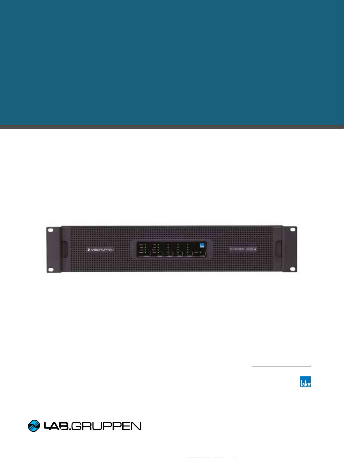
D SERIES
High-Power installation platform
Lake Variants:
D 200:4L
D 120:4L
D 80:4L
Incorporating technologies from
Quick Start Guide
Page 2

1. Important safety instructions
1. Important safety instructions
Before using the device, be sure to carefully read the Safety Instructions. Keep this document with the device at
all times.
1. Read these instructions.
2. Keep these instructions
3. Heed all warnings.
4. Follow all instructions.
5. Do not use this apparatus near water.
6. Clean only with a dry cloth.
7. Do not block any ventilation openings. Install in accordance
with the manufacturer’s instructions.
8. Do not install near any heat sources such as radiators, heat
registers, stoves, or other apparatus (including ampliers)
that produce heat.
9. Do not defeat the safety purpose of the polarized or
grounding-type plug. A polarized plug has two blades with
one wider than the other. A grounding-type plug has two
blades and a third grounding prong. The wide blade or
the third prong is provided for your safety. If the provided
plug does not t into your outlet, consult an electrician for
replacement of the obsolete outlet.
10. Protect the power cord from being walked on or pinched,
particularly at plugs, convenience receptacles, and the point
where they exit from the apparatus.
11. Only use attachments/accessories specied by the
manufacturer.
12. Use only with a cart, stand, tripod, bracket, or table specied
by the manufacturer, or sold with the apparatus. When a
cart is used, use caution when moving the cart/apparatus
combination to avoid injury from tip-over.
13. Unplug this apparatus during lightning storms or when
unused for long periods of time.
14. Refer all servicing to qualied service personnel. Servicing
is required when the apparatus has been damaged in any
way, such as power-supply cord or plug is damaged, liquid
has been spilled or objects have fallen into the apparatus, the
apparatus has been exposed to rain or moisture, does not
operate normally, or has been dropped.
15. Use the mains plug to disconnect the appartus from the
mains.
16. WARNING: To reduce the risk of re or electric shock, do not
expose this apparatus to rain or moisture.
17. Do not expose this equipment to dripping or splashing and
ensure that no objects lled with liquids, such as vases, are
placed on the equipment.
18. The mains plug of the power supply cord shall remain readily
operable.
19. Do not connect the unit’s output to any other voltage source
such as battery, mains source, or power supply, regardless
of whether the unit is turned on or off.
20. Do not remove the top (or bottom) cover. Removal of the
cover will expose hazardous voltages. There are no user
serviceable parts inside and removal may void the warranty.
21. An experienced user shall always supervise this professional
audio equipment, especially if inexperienced adults or
minors are using the equipment.
22. The US National Differences clause 16.3 requires that
network cables must be ame rated VW-1.
2. Approvals
This equipment conforms to the requirements
of the EMC Directive 2004/108/EC and the
requirements of the Low Voltage Directive
2006/95/EC.
Standards applied: EMC Emission
EN55103-1, E3
EMC Immunity EN55103-2, E3, with S/N
below 1% at normal operation level.
Electrical Safety EN60065, Class I
This equipment is tested and listed according to the
U.S. safety standard ANSI/ UL 60065 and
Canadian safety standard CSA C22.2
NO. 60065. Intertek made the tests and they
are a Nationally Recognized Testing Laboratory
(NRTL).
3. Warnings
3.1. Explanation of warning symbols
The lightning bolt triangle is used to
alert the user to the presence of
un-insulated “dangerous voltages”
within the unit’s chassis that may be
of sufcient magnitude to constitute a
risk of electric shock to humans.
The exclamation point triangle is used to
alert the user to presence of important
operating and service instructions in the
literature accompanying the product.
3.2. Warnings
To prevent electric shock do not remove top or bottom
covers. No user serviceable parts inside, refer servicing to
qualied service personnel.
Français: À prévenir le choc électrique n’enlevez pas les
couvercles. Il n’y a pas des parties serviceable à l’intérieur, tous
reparations doit etre faire par personnel qualié seulment.
D SERIES Lake Quick Start Guide rev 1.2.0
2
Page 3
3. Warnings
To completely disconnect this equipment from the AC
mains, disconnect the power supply cord plug from the AC
receptacle. The mains plug of the power supply cord shall
remain readily operable.
Français: Pour démonter complètement l’équipement de
l’alimentation générale, démonter le câble d’alimentation
de son réceptacle. La prise d’alimentation restera aisément
fonctionnelle.
To reduce risk of re or electric shock, do not expose this
apparatus to rain or moisture.
Français: Pour réduire les risques d’incendie ou de choc
électrique, n’exposez pas l’appareil à la pluie ou à l’humidité.
Do not expose this system/apparatus to dripping or splashing
and ensure that no objects lled with liquids, such as vases,
are placed on the apparatus.
Français: N’exposez pas ce système/appareil au
ruissellement ni aux éclaboussures et assurez-vous qu’aucun
objet contenant du liquide tel qu’un vase n’est placé sur
l’appareil.
This apparatus must be connected to a mains socket outlet
with a protective earthing connection.
Français: Cet appareil doit être raccordé à une prise secteur
avec terre de protection.
The mains plug is used as a disconnect device and shall
remain readily operable.
Français: Lorsque la prise du réseau d’alimentation est utilisés
comme dispositif de déconnexion, ce dispositif doit
demeuré aisément accessible.
3.3. Caution
To reduce the risk of re or electric shock, do not remove screws.
No user-serviceable parts inside. Refer servicing to qualied
service personnel.
Français: Pour réduire le risque d’incendie ou de choc
électrique, ne pas retirer les vis. Aucune pièce réparable par
l’utilisateur. Coner l’entretien àpersonnel qualié.
3.4. User responsibility
3.4.1. Mains connection grounding
Your amplier must be connected to a grounded socket outlet.
3.4.2. Speaker output hazard on amplifiers
Ampliers are capable of producing hazardous output
voltages. To avoid electrical shock, do not touch any exposed
speaker wiring while the amplier is operating. The external
wiring connected to the speaker terminals shall be installed
by a qualied person, or ready-made leads or cords of
appropriate capacity shall be used.
As the power output channels on ampliers produce high
voltage, do not connect or disconnect speaker cables when
the mains power is on.
3.4.3. Radio interference
A sample of this product has been tested and complies with
the limits for the European Electro Magnetic Compatibility
(EMC) directive. This equipment has also been tested and
found to comply with the limits for a Class A digital device,
pursuant to Part 15 of the FCC Rules. These limits are
designed to provide reasonable protection against harmful
interference from electrical equipment. This product uses
radio frequency energy and if not used or installed in
accordance with these operating instructions, may cause
interference to other equipment, such as radio receivers.
This Class A digital apparatus complies with Canadian ICES-003.
Cet appareil numérique de la classe A est conforme à la norme NMB-003
du Canada.
However, there is no guarantee that interference will not
occur in a particular installation. If this equipment does cause
harmful interference to radio or television reception, which
can be determined by turning the equipment on and off, the
user is encouraged to try to correct the interference by one or
more of the following measures:
• Reorient or relocate the antenna.
• Increase the separation between the equipment and
re cei ver.
• Connect the equipment to an outlet on a circuit different
from that to which the receiver is connected.
• Check if the affected unit complies with the EMC limits for
immunity, (CE-labeled). If not, address the problem with
the manufacturer or supplier. All electrical products sold
in the EC must be approved for immunity against
electromagnetic elds, high voltage ashes, and radio
interference.
• Consult the dealer or an experienced radio/TV technician
for help.
3.4.4. Speaker damage
Amplier apparatus is very powerful and can be potentially
dangerous to both loudspeakers and humans alike. Many
loudspeakers can be easily damaged or destroyed by
overpowering them. Always check the speaker’s continuous
and peak power capabilities. Although the ampliers
attenuators can be used to reduce the overall gain, an
increase of the input signal can result in full output power,
which may cause damage to connected speakers.
3.4.5. Maintenance
For safe and reliable operation, the dust lters on both sides
of the front panel, behind the grilles, should be removed and
cleaned regularly to ensure maximum airow through the
device.
If the dust lters are not maintained there will be safety
risks; for example, high internal temperatures could ignite
the dust and start a re. There is also a risk that the unit will
malfunction since it is dependent on constant airow from
front to rear. If the dust lters are not clean and the unit
malfunctions, any resulting problems will not be covered by
the warranty.
D SERIES Lake Quick Start Guide rev 1.2.0
3
Page 4

4. Table of Contents
4. Table of Contents
1. Important safety instructions 2
2. Approvals 2
3. Warnings 2
3.1. Explanation of warning symbols 2
3.2. Warnings 2
3.3. Caution 3
3.4. User responsibility 3
3.4.1. Mains connection grounding 3
3.4.2. Speaker output hazard on ampliers 3
3.4.3. Radio interference 3
3.4.4. Speaker damage 3
3.4.5. Maintenance 3
5. Introduction 6
5.1. Welcome 6
5.2. D Series: Two versions available 6
6. Feature summary 7
6.1. Features unique to Lake variants 7
7. Installation 8
7.1. Unpacking 8
7.1.1. Included in the box 8
7.2. Mounting 8
7.2.1. Rear Mounting 8
7.2.2. Mounting front grille 9
8. Cooling and fan operation 10
D SERIES Lake Quick Start Guide rev 1.2.0
4
Page 5

4. Table of Contents
9. Operating voltage 10
9.1. Low voltage country considerations 10
10. Grounding 11
11. Product overview 12
11.1. Front panel 12
11.1.1. Additional front panel operations and indications 14
11.2. Rear panel 15
12. Signal ow and processing 16
13. Quick Start Tutorial 17
13.1. Network setup 17
13.1.1. Network connections/topology 17
13.1.2. Network conguration 17
13.2. Software installation and rmware update 18
13.2.1. Lake Controller software suite 18
13.2.2. CAFÉ software 18
13.2.3. Firmware update 18
13.3. System setup 19
14. Faults and warnings 23
15. Technical Specications 26
16. Warranty and support 28
16.1. General 28
16.2. Technical assistance and service 28
16.2.1. International service 28
16.2.2. Factory service 29
D SERIES Lake Quick Start Guide rev 1.2.0
5
Page 6

5. Introduction
5. Introduction
5.1. Welcome
Thank you for choosing the Lab.gruppen D Series for your sound reinforcement needs. We are condent that you
will be pleased with the performance, unique features, conguration exibility, reliability, and long-term durability
offered by this product.
For fast installation and use of this product, your welcome package includes this printed copy of the D Series
Quick Start Guide. It provides a brief introduction to the features and functionality of the D Series, and it also
contains the information required to safely install the product and place it in service. Please read through thoroughly
to become acquainted with the basic conguration and control options available. It is recommended that you also
review all other product documentation to ensure familiarity with the various conguration and control options.
Thank you again for placing your condence in Lab.gruppen products.
5.2. D Series: Two versions available
D Series is an advanced, high-power installation amplier platform designed for demanding applications, primarily
in performance venues. For the utmost exibility in processing and networking, the D Series is available in two
versions: the Lake version, with a full slate of Lake processing algorithms and Dante networking; and the Tesira by
Biamp option for full integration in a Tesira system and with Ethernet AVB audio transport. Both D Series Versions
are available in three output power levels and offer unique power management features.
This Quick Start Guide is for use with Lake processing versions only, and applies to models at all three output
power levels. More detailed information is available in the full Operation Manual, available at Lab.gruppen.com.
D SERIES Lake Quick Start Guide rev 1.2.0
6
Page 7

6. Feature summary
6. Feature summary
• Four channels with three levels of total available frame power output: 20000 W, 12000 W and 8000 W
• Rational Power Management (RPM)
• True exibility in allocating power output across each channel to match requirement, for more efcient use
of amplier inventory
• Any channel is capable of delivering up to 5000 W power output from total available power in each frame
• Dedicated on-board surveillance and load monitoring for voice alarm applications
• Advanced universal power supply
• Regulated Switch-Mode Power Supply (R.SMPS™) maintains stability through uctuations in mains voltage
• Best-in-class Power Factor Correction (PFC)
• Current Draw Modeling (CDM™) reduces peak mains draw
• Breaker Emulation Limiter (BEL™) responds to available mains distribution
• Under-Voltage Limiting (UVL™) allows continued operation through mains voltage drop
• CAFÉ (Conguring Ampliers For the Environment) software incorporates ESP™ (Equipment Specication
Predictor) to assist in design, equipment specication and commissioning
• Features controlled by on-board DSP
• Input Gain (Sensitivity) - Input gain (sensitivity) is set in the digital domain and controlled via CAFÉ software
• ISVPL™ - The Inter-Sample Voltage Peak Limiter (ISVPL) tailors each channel’s power output to the
characteristics of the connected load
• Load Verication & Performance Monitoring - A comprehensive set of proprietary DSP-based tools
enables load verication and real-time performance monitoring
6.1. Features unique to Lake variants
• Lake’s exclusive classic/linear-phase/FIR speaker processing platform with four throughputs
• Group control with Raised Cosine™ MESA EQ™ asymmetric lters
• LimiterMax™ peak and RMS limiters
• Extensive loudspeaker preset database (Lake LoadLibrary™)
• Comprehensive clocking management system with low latency sample rate conversion
• Full support for Dante Controller
• Multiple and redundant inputs with programmable failover
• Four “Lake Class” analog inputs with Iso-Float™ ground isolation
• Two AES3 digital inputs (4 audio channels)
• Eight dual-redundant Dante network audio inputs
• Comprehensive 3rd party protocol for integration potential with third party matrix systems via purpose-
developed middleware
D SERIES Lake Quick Start Guide rev 1.2.0
7
Page 8

7. Installation
7. Installation
7.1. Unpacking
Carefully open the shipping carton and check for any damage to the device or the supplied accessories. Every
Lab.gruppen product is tested and inspected before leaving the factory and should arrive in perfect condition. If
any damage is discovered, please notify the shipping company immediately. Only the consignee may initiate a
claim with the carrier or their insurers for damage incurred during shipping. Save the carton and packing materials
for the carrier’s inspection.
7.1.1. Included in the box
In addition to the D Series device, the shipping carton includes the following items:
• D Series Lake Quick Start Guide (this document)
• AC mains lead (power cable) with Neutrik® powerCON® connector and AC socket plug according to
ordering selection
• Rear brackets for additional rack support (pair) along with associated mounting hardware
• Connector kit including all needed connectors
• Front grille and dust lter assembly
NOTE: Depending on the model, the connector kit might include more connectors than applicable for the product
you have. Select those connectors required for your unit and application.
Please keep the original carton and associated packaging to facilitate shipping of the device should the need arise.
7.2. Mounting
D Series is made for mounting in 19 inch racks. Four screw holes are available for attachment of the amplier to
the racks front rack rail. This device has no top or bottom vents; therefore, units may be stacked directly on top of
one another. Sufcient space should be available at the rear to accommodate connectors and cables. In addition,
allowance must be made for cable or loom bends within a rack.
7.2.1. Rear Mounting
Two rear support brackets, along with associated mounting hardware, are included with the D Series device. It is
strongly recommended that these are used wherever possible. Fit the brackets to the vertical rails at the rear of the
rack. The following diagrams show the tting options for xed and removable installation. The support brackets are
reversible and may be tted to point either to the front or rear of the rack; the proper orientation depends on the
rack depth and position of the rear rack rails.
D SERIES Lake Quick Start Guide rev 1.2.0
8
Page 9
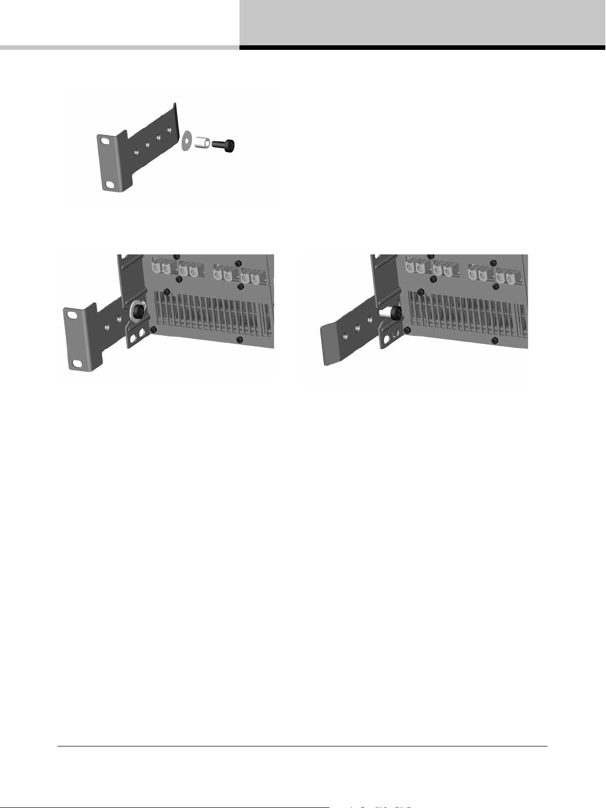
Rear support bracket with mounting hardware
7. Installation
Rear support bracket mounted for xed Rear support bracket mounted for removable
installation and bracket pointing forward installation and bracket pointing towards back
7.2.2. Mounting front grille
The front grille is shipped on top of the amplier inside the box to protect it during shipping. The front grille adheres
to the amplier with magnets. Hold the front grille with your ngers in each of the side cutouts and slide it gently into
place straight from the front.
NOTE: Always ensure the dust lters behind the detachable front panel are clean to ensure maximum possible
airow. The exterior front panel is held in place by powerful magnets but is easy to detach by using your ngers in the
openings at the each side. To clean the foam lter, detach it from the exterior front and gently use a vacuum cleaner
or gently shake it. Remount with the opposite procedure. Never operate the amplier without the dust lter installed.
D SERIES Lake Quick Start Guide rev 1.2.0
9
Page 10

8. Cooling and fan operation
8. Cooling and fan operation
D Series devices use a forced-air cooling system with airow from front to rear, allowing high continuous power
levels without thermal problems. To facilitate maximum air ow, ensure that no objects such as rack doors or
lids are placed at the front or rear of the rack. Never attempt to reverse the airow. Make sure an adequate air
supply is provided in front of the D Series device, and that the rear of the device has sufcient space to allow
air to escape. It is recommended to keep the ambient temperature around the device as cool as possible. An
increased temperature can have a signicant negative impact on the expected lifetime on the components
inside the D Series device.
NOTE: Fit solid blanks (not ventilation blanks) to unused rack spaces to ensure effective air circulation. Leaving
gaps in between items of equipment degrades the effectiveness of forced-air cooling.
If installing one or more D Series devices in a rack with other fan-cooled equipment, conrm that all other
equipment also uses front-to-rear airow for cooling. If this precaution is not observed, there is a risk of
overheating, as units with the reverse airow will be drawing in air which has already been heated by the
D Series devices.
The D Series device is equipped with a sophisticated temperature sensing system which protects it from any
overheating which may occur as a result of inadequate ventilation.
9. Operating voltage
D Series has a universal power supply and its mains nominal and operating voltages are specied in the Technical
Specications (pages 26-27). D Series can be ordered with a variety of mains plugs. If the mains plug (AC plug)
tted to the mains cable (AC cord) is not appropriate for your country it can be removed and a locally-sourced one
tted instead. If you are not 100% condent of your competence to replace the mains plug (AC plug), the task
should be carried out by qualied personnel.
NOTE: In-rush current is controlled and limited during the soft-start sequence. This enables multiple D Series
Devices on the same AC mains circuit to be turned on simultaneously.
9.1. Low voltage country considerations
Although the D Series has a wide range of operating mains voltage, some considerations can be applicable for
low voltage regions. D Series performs well throughout the specied nominal voltage range but has slightly better
efciency at higher voltages. For regions with nominal voltage below 140 V, one could consider connecting the
amplier in a three-phase delta or two phase split-phase conguration.
NOTE: Following connections applicable only for resulting voltage inside the ampliers nominal voltage range.
D SERIES Lake Quick Start Guide rev 1.2.0
10
Page 11

10. Grounding
Connecting the amplier in three phase delta conguration
In three-phase conguration where the phases are 120 degrees apart, one can connect three balanced loads in a
delta conguration. The connection is made between the phases instead of between the neutral and a phase.
208V
120V
L1
Amp
L2
Amp
L1 L2
N N
Amp
120V
L3
120V
208V
Amp
Amp
Amp
208V
L3
3 phase Y 120V
3 phase delta 208V
Three phase delta conguration
Connecting the amplier in a split phase conguration
In two phase split-phase conguration there are two phases separated by 180 degrees. Connecting between the
phases gives double the line voltage.
100V 100V 200V
Amp
L1
Split phase 100V
Amp
L2N
L1 L2
Amp
N
Split phase 200V
Two phase split-phase conguration
10. Grounding
Use correctly-shielded balanced audio input connections to minimize hum and interference.
D Series must be grounded (earthed) with the safety ground pin to the mains distribution system.
NEVER disconnect the earth (ground) pin on the mains cable (AC power cord).
D SERIES Lake Quick Start Guide rev 1.2.0
11
Page 12

11. Product overview
11. Product overview
11.1. Front panel
1
The front panel is consists of an outer front with air intake and a centered user interface. The user interface has
LEDs for monitoring and six recessed touch buttons for control.
1 Rack ears for 19 inch rack mount
2 Exterior front grille (also air intake and dust lter holder)
3 4 7 8
65
USER INTERFACE
Frame Status and Control
3 FRAME LED for frame related status indication
4 TEMP LED for temperature related status indication
5 PSU LED for the status indication related to Power Supply Unit or mains supply
6 POWER LED and TOUCH BUTTON for power state indication and control. Press and hold button to toggle
the amplier between ON and STANDBY state
Channel Status and Control
7 LOAD LED for load related status indication
8 AMP LED for amplier related status indication
9 SIGNAL LED for signal related status indication
10 MUTE LED and TOUCH BUTTON for mute status indication and control. A single touch on the mute button
toggles the power channel mute between mute and unmuted states.
11 SELECT LED and TOUCH BUTTON for selection and indication control between computer software and
unit. A single touch on the button will select the unit in supported computer software views. Multiple consecutive
touches will select the corresponding module (one touch for module A, 2 for module B etc.). In the other direction,
when selecting the unit in a supported computer software view, the LED will indicate the unit is selected.
9
11
NOTE: The touch buttons use capacitive touch technology and might be sensitive to large temperature and
humidity variations.
D SERIES Lake Quick Start Guide rev 1.2.0
12
Page 13

11. Product overview
OFF Green Amber Red
Frame
N/A Frame OK Frame warning Frame fault
Tem p
N/A Te mp O K Tem p wa rn ing Temp fault
PSU
N/A PSU OK
Power supply/
Mains warning
Power supply/
Mains fault
Power
No mains power
Fixed:ON
Blinking: Turning ON
Button pressed.
Hold for transition
Fixed: STANDBY
Blinking: Turning to
STANDBY
Load
No LoadPilot active
LoadPilot active
and LoadOK
Load warning Load fault
Amp
N/A Power channel OK Power channel warning Power channel fault
Signal
Signal below signal
present threshold (-60 dB)
Signal above signal
present threshold (-60 dB)
Signal approaching
input clip (-2 dB)
Signal clip
or limit/fault active
Mute
Inactive channel in
bridge operation
Unmuted
Lake module is muting the
signal chain at either input
router, module input or
module output
Power channel muted
Select
Frame not selected Frame selected Waiting for more touches N/A
Table 1 LED/category chart
NOTE: See Faults and warnings (pages 23-25) for a detailed description of status, faults and warnings associated
with each LED.
D SERIES Lake Quick Start Guide rev 1.2.0
13
Page 14

11. Product overview
11.1.1. Additional front panel operations and indications
Frame reset
A factory reset and soft reset can be performed from the front panel. A factory reset will restore all settings to
original defaults, including network settings, frame presets and current settings. A soft reset reverts only the current
settings to default. Network settings and frame presets are not changed with a soft reset.
1. Place the frame in standby mode.
2. Press and hold elect and channel 3 mute button. Then press the power button.
3. Choose from one of the below operations:
a. Press channel 1 mute button (red LED) to initiate the factory reset sequence.
b. Press channel 2 mute button (amber LED) to initiate the soft reset sequence.
c. To cancel, press channel 4 mute button (green LED).
4. Wait state indication is present while either reset is performed.
5. To complete the factory reset process, cycle the mains power by completely removing the power plug and
reinserting it.
Wait indication
Wait indication is displayed when the frame is performing an operation. All LEDs except power are unlit and a
circling amber light is displayed on channels 1 and 2.
Power cycle required indication
After an operation that requires a subsequent power cycle to complete, the power LED blinks alternately red and
green.
D SERIES Lake Quick Start Guide rev 1.2.0
14
Page 15

11. Product overview
11.2. Rear panel
1 2 3 4
1 Amplier Outputs - The amplier output connectors are sturdy terminal block connectors. See Technical
Specications (pages 26-27) for connector rating. Channels are located from left to right. Each channel has a
clearly marked hot (+) and cold (-) terminal
2 Analog Inputs - Analog inputs are available on terminal block connectors with clearly marked hot (+), cold (-)
and ground terminals
5
3 AES3 Inputs - AES3 inputs are available on terminal block connectors with clearly marked hot (+), cold (-)
and ground terminals
4 RJ-45 Ethernet connectors for control and Dante digital audio network
5 Mains connector - Detachable Neutrik powerCON. See data sheet for connector rating
D SERIES Lake Quick Start Guide rev 1.2.0
15
Page 16

12. Signal flow and processing
12. Signal flow and processing
The table below is the signal ow diagram for D Series Lake versions.
Module Data stored in Module FIles (Speaker Presets)
Frame Data stored in System Files and Frame Presets
INPUTS
Dante Receivers 1-8
AES/Analog
pass through
to Dante
AES 1-4
Analog 1-4
OUTPUTS
Dante 1-8
(no mutes)
Input
Routers
1-4
WITH
INPUT
MUTES
Input
Mixer A
Input
Mixer B
Input
Mixer C
Input
Mixer D
Lake Contour
Module A
Lake Contour
Module B
Lake Contour
Module C*
Lake Contour
Module D*
Attenuator
Phase Rev
Custom RPM
Attenuator
Phase Rev
Custom RPM
Attenuator
Output Routing
Phase Rev
Custom RPM
Attenuator
Phase Rev
Custom RPM
Mute
Mute
Mute
Mute
ISVPL
Auto RPM
ISVPL
Auto RPM
ISVPL
Auto RPM
ISVPL
Auto RPM
Amp Gain LoadSmart LoadPilot AMP
Amp Gain LoadSmart LoadPilot AMP
Amp Gain LoadSmart LoadPilot AMP
Amp Gain LoadSmart LoadPilot AMP
1 2 43 5
1 The input section (inputs, input router and input mixer) allows for mixing capabilities as well as redundant and
prioritized inputs with automatic switch-over in case of signal failure
2 Up to four Lake Processing modules provide user EQ and loudspeaker processing, including LimiterMax limiting
3 The Output router allows free routing between module outputs and power output channels
4 Each power output channel provides individual channel processing, including ISVPL limiter, RPM and load
monitoring
5 Power amplier
D SERIES Lake Quick Start Guide rev 1.2.0
16
Page 17

13. Quick Start Tutorial
13. Quick Start Tutorial
This section will describe how to get started with associated software and set up a basic system for operation.
13.1. Network setup
13.1.1. Network connections/topology
Each frame has two network ports; a primary and a secondary. See the below diagram for a typical network
topology using the primary ports.
By default, the secondary ports are congured in Dual redundancy mode to support a second redundant network.
The alternate conguration for the two ports is a switch mode which allows daisy-chaining devices in a single
network. Daisy chain mode is not recommended for more than a few devices, and for not more than two if running
Dante audio along with control data.
Computer
Switch
D Series Lake
D Series Lake
D Series Lake
D Series Lake
D Series Lake
D Series Lake
Wireless
Access Point
Switch
D Series Lake
D Series Lake
D Series Lake
D Series Lake
D Series Lake
D Series Lake
NOTE: If using Dante audio in the network, the audio trafc needs to be ltered from reaching the wireless links.
13.1.2. Network configuration
Frames are congured by default to obtain IP addresses automatically. The frame will assign itself an IP address
in the link local range (169.254.1.0 through 169.254.254.255). If a computer is congured the same way
(which should be default on modern operating systems), it will reside in the same subnet as the devices and
communication can be established. Alternate congurations would be DHCP for a managed network or xed IP.
To connect to the secondary network in Dual redundancy mode the computer shall be congured with an IP
address in the 172.31.0.0 - 172.31.255.255.
D SERIES Lake Quick Start Guide rev 1.2.0
17
Page 18

13. Quick Start Tutorial
13.2. Software installation and firmware update
13.2.1. Lake Controller software suite
1. The Lake controller software suite includes the Lake controller and accompanying utilities: Lake LoadLibrary,
Dante discovery services and CAFÉ. Download the Lake Controller installation from www.labgruppen.com.
2. Execute the installer and follow the on-screen instructions. This is a typical software installation where the
default settings are acceptable for the vast majority of users.
13.2.2. CAFÉ software
1. The CAFÉ software is included in the Lake controller suite installer but is also available as a separate installer
on www.labgruppen.com.
2. Execute the installer and follow the on-screen instructions. This is a typical software installation where the
default settings are acceptable for the vast majority of users.
13.2.3. Firmware update
The latest rmware for the product is included in the Lake controller installation. It is likely that rmware installed on
the new product is older and requires updating.
1. Make sure all frames are powered on and connected through a wired network.
2. Launch the Lake rmware update utility LakeUpdate.exe.
3. Select the appropriate product range.
4. If more than one network adapter is enabled, a prompt will appear requiring selection of the adapter connected
to the frames.
5. If prompted, allow the application access through the Firewall.
6. Latest rmware is preselected.
7. Discovered frames are listed. Tap Select Old and Update to initiate rmware update of all outdated frames.
Frames already up to date will not be selected.
8. Read warning message and tap OK.
9. Wait for all updates to be completed. A wait indication will display on the unit(s) during updating.
10. Tap OK and cycle the mains power on all updated frames by completely removing the power plug and
reinserting it. (Note: The standby button does not complete the rmware update).
11. If internal updates are needed, these will be performed by the frame after the power cycle. A wait indication is
displayed.
12. Tap Exit to close the update utility.
D SERIES Lake Quick Start Guide rev 1.2.0
18
Page 19

13. Quick Start Tutorial
13.3. System setup
This tutorial provides a step-by-step guide for conguration of a typical professional loudspeaker system and
provides an overview of the basic features and operation of the frame. This tutorial describes how to congure
4-channel frame for use with a generic 3-way loudspeaker system (with separate HF, MF and LF drivers), plus
a separate subwoofer. It assumes that the system is fed with analog outputs from a mixing console with one
fullrange main output and a separate sub feed.
1. Connect the loudspeakers to the four power output channels:
a. Channel 1 – Low Frequency Driver
b. Channel 2 – Mid Range Driver
c. Channel 3 – High Frequency Driver
d. Channel 4 – Subwoofer
2. Connect the main output of the mixing console to analog input 1 of the frame and the sub feed to input 2.
While conguring, it is a good practice to make sure the volume is turned down on the console.
3. Ensure the frame is powered on and is in its default state, and that the computer has established an active
Ethernet connection.
4. On the Tablet PC, launch the Lake Controller software application. Select the appropriate network adapter if
more than one is enabled, and tap NO to the dialog asking whether to load the previous conguration.
5. Tap MODULES button on the menu bar at the bottom of the screen to access the Module Menu and scroll
bar.
6. On the Module scroll bar, the frame is represented with a frame containing four discs. These are labeled A, B,
C and D, each representing one of the four Lake processing modules.
7. Tap the frame to select it, then tap again in the MAIN area of the screen to place all modules of the frame in
the current system conguration. The Lake Controller uploads settings from the frame.
8. Tap the icon for Module A; its border will turn yellow to conrm selection and an LED on the front panel of the
associated device will illuminate.
9. Tap the Module Store/Recall button on the Modules Menu; the menu will change to show additional options.
10. Double-tap the Default Modules folder, then double-tap the Contour Classic Crossovers folder. A set of
loudspeaker symbols will be displayed.
11. Tap CL3way, and then tap the RECALL button. This congures the DSP for the Module A as a 3-way
crossover for the 3 way speaker.
12. Tap Yes when asked to conrm that all data will be overwritten.
13. An Output conguration dialog will pop up to allow for routing of module outputs to power channels. Tap the
orange number buttons in the matrix to un-route, freeing up a power channel. Tap a blue number button at
the intersection of the appropriate module output and power channel, routing the module output to the power
channel. Proceed until you have routing according to the picture below and tap the bottom right return button
to exit the dialog.
D SERIES Lake Quick Start Guide rev 1.2.0
19
Page 20

13. Quick Start Tutorial
1
2
3
4
Bridge Bridge
14. The B module is already a CL1way as default and can be used to drive the sub.
15. Tap Store/Recall EXIT to return to the Modules Menu.
16. Ensuring Module A (or any other module that you want to control) is selected (yellow border), tap I/O Cong.
17. The right side of the I/O CONFIG screen displays a block diagram for the Modules. Tapping the different blue
blocks will access the conguration screens for Input mixer, Levels, Input EQ, Delay and Output EQ/Crossover
respectively. The magnifying glass at the far right end accesses the output conguration. (NOTE: Tapping the
blue return button (left arrow), or the EQ/Levels EXIT button in the menu bar returns to the I/O Cong screen
from the various conguration screens.)
Input Mixer Conguration - Drag sliders and tap ON/OFF buttons to control input mixer settings.
D SERIES Lake Quick Start Guide rev 1.2.0
20
Page 21

13. Quick Start Tutorial
Levels Control - Drag sliders and tap mute buttons for module
input and output channels.
Delay Control - Drag sliders to control input and output delay Crossover control – Select lters and drag on the bottom
Parametric EQ control – Select lter on the top squares
and adjust lter properties by dragging the controls. Sliders
at the bottom control center frequency and Q (bandwidth).
Gain is controlled in the main window area. Additional lters
can be added by tapping the top lter objects and placing
new lters on the main area.
frequency bar to adjust crossover frequency. Crossover
types may be changed by selecting the Crossover
Functions button.
18. Tap the Input Gain button in the block diagram and unmute the Module Input Mute. Tap EQ/Levels Exit to return to
IO Cong.
19. The left side of the IO cong screen holds frame conguration and summary for Clock conguration, Input
conguration, Dante conguration, Breaker Emulation Limiter conguration and Analog Iso-Float & AES Termination
conguration. All these congurations should be correct by default for this example.
20. From I/O CONFIG, tap EVENTS & CONTROL and navigate to the STATUS tab. Unmute the power channels and
slowly increase the volume on the appropriate feed from the mixing console. Audio should now be active at the
outputs and heard through the loudspeakers. Close the Events and Control dialog with the return button and return
to the main area by tapping the I/O Cong EXIT button.
Events & Control, Status tab – Drag sliders to adjust power channel attenuation and tap mute buttons to
control power channel mute. Metering and Status monitoring is available for each power channel.
D SERIES Lake Quick Start Guide rev 1.2.0
21
Page 22

13. Quick Start Tutorial
21. Repeat step 16 and 20 for the B module. On the Output EQ/Crossover, tap the Aux Output Functions
button on the menu bar and then tap LPF Enable button. Drag the Low pass lter control object on the
frequency slider just above the menu bar to an appropriate crossover frequency for the sub, e.g. 100 Hz.
Output EQ control - Add LPF/HPF and EQ lters and drag to adjust.
22. Use the control options mentioned in 17 to tune your loudspeakers. For larger systems, modules can be
placed in groups (Groups menu from the MAIN page) for control of multiple units.
23. Some features like RPM can only be congured from within CAFÉ software. Return to EVENTS & CONTROL;
from the main area hit MODULES button, select a module (e.g. Module A), tap I/O Cong, tap EVENTS &
CONTROL, and navigate to the Control tab. The CAFÉ button (next to bottom) opens the CAFÉ application
and imports and highlights the current amplier and its RPM view.
CAFÉ, RPM view – Enter power requirements for various channels and automatically congure RPM.
D SERIES Lake Quick Start Guide rev 1.2.0
22
Page 23

14. Faults and warnings
Category/Type Name On screen text Description Action
FRAME
Warning
Lake Controller ofine CTRL OFFLINE
Frame unable to nd Lake controller
on the network
Check network cabling/
network if controller
expected on the network
Warning
AES clock slipping CLOCK SLIPPING
Frame not able to lock to
incoming A ES stream
Check AES sender and
clock conguration
Warning
Dante device na me conict NAME CONFLICT
Two or more devices on the network
with the same Dante name
Review Dante
conguration
Warning
Dante module not detected
DANTE NEEDS
SERVICE
Lake cannot detect a functioning
Dante module
Restart device; if not
cleared it needs service
to operate Dante
Warning
Dante module with
incompatible rmware
DANTE FW INVALID
Dante module not loaded
with correct FW
Retry updating the rmware
with LakeUpdate
Fault
Audio Fault AUDIO FAULT
Internal audio interface
not functioning
Restart device; if not
cleared it needs service
Fault
Sense fault D SP SENS FLT:DSP
Voltage and current sensing on amplier
output fault y. Audio continues but
protection might be compromised.
No load monitoring
Restart device; if not
cleared it needs service
Fault
A/D converter power
supply fault
A/D P SU FAULT
Voltage supply to the analog input
converters faulty
Restart device; if not
cleared it needs service for
analog input to work
TEMP
Warning
Temperature warning
power supply
TEMP WARN:PSU
Power supply temperature
approaching critical levels
Improve cooling or reduce
output power to avoid
temperature becoming
critical
Warning
Temperature warning
DSP area
TEMP WARN:DSP
DSP area temperature approaching
critical levels
Improve cooling or reduce
output power to avoid
temperature becoming
critical
Warning
Power supply
Temperature Limit
PTL ACTIVE
Amplier is reducing output power
to avoid power supply temp
fault protection
Improve cooling or reduce
output power to avoid
limiting
Warning
Amp channel
Temperature Limit
ATL ACTIVE
Amplier channel is reducing output
power to avoid amplier channel
temp fault protection
Improve cooling or reduce
output power to avoid
limiting
Fault
Temperature fault
power supply
TE MP F LT:PS U
Power supply temperature reached
internal protection limit
Automatically restarts
when cooled down
Fault
Temperature fault
DSP area
TE MP F LT:D SP
DSP area re ached
critical temperature
Improve cooling or
reduce power
14. Faults and warnings
D SERIES Lake Quick Start Guide rev 1.2.0
23
Page 24

14. Faults and warnings
Category/Type Name On screen text Description Action
PSU
Warning
Under Voltage Limit UVL ACTIVE
The Under Volt age limiter is active as the
mains supply is approaching the lower
end of the device´s operational voltage.
Output power is decreased to ensure
mains distribution does not collapse
Increase mains distribution
stiffness or reduce output
power to avoid limiting
Warning
Power Average Limit PAL ACTIVE
Amplier is reducing output power due
to average power or mains current
draw is above safe operating levels
Reduce output power
to avoid limiting
Warning
Breaker Emulation Limit BEL ACTIVE
Power supply is reducing mains current
draw to stay within B EL congured
nominal current and prole
Improve mains distribution
and update BEL
conguration or reduce
output power to avoid
limiting
Warning
Mains supply glitch MAINS GLITCH
Mains glitch (missing cycles) was
detected on the mains inlet
Check mains distribution/
connection
Warning
Upgrade power
supply rmware
UPGRADE PSU
Power supply rmware version not
compatible with amplier
Upgrade amplier
rmware
Fault
Need service NEED SERVICE:1-8 Power supply internal error
Restart device; if not
cleared it needs service
Fault
Mains voltage above
400 volt peak
MAINS>400 VPK
Power supply detects mains voltage
above 40 0 volt peak. Protective shut
down, auto restart attempt
Check mains distribution/
connection
Fault
Mains voltage above
270 V
MAINS>270 V
Power supply detects mains voltage
above operation voltage. Protective
shut down, auto restart attempt
Check mains distribution/
connection
Fault
Mains voltage below
65 V
Mains<65 V
Power supply detects mains voltage
below operation voltage. Protective
shut down, auto restart attempt
Check mains distribution/
connection
Fault
Power supply fault PS U FAU LT Internal power supply fault
Check mains distribution/
connection. Restart
device; if not cleared
it needs service
Fault
Check mains CHECK MAINS
Power supply detects unstable mains
supply. Protective shut down, auto
restart at tempt
Check mains distribution/
connection
Fault
Power supply power protect PSU POWER PROT
Too high output power for too low mains
supply voltage. Protective shut down,
auto restart attempt
Improve mains supply
voltage or reduce
output power
LOAD
Warning
Speaker short SPKR SHORT Both LoadPilot tones below thresholds Check load or calibration
Warning
Speaker damaged SPKR DAMAGED
One LoadPilot tone is above
or below threshold
Check load or calibration
Warning
Under speaker count UNDER SPKR CNT
Both LoadPilot tones above thresholds
or LoadSmart detected fewer
speakers than expected
Check load and
cabling alibration
D SERIES Lake Quick Start Guide rev 1.2.0
24
Page 25

Category/Type Name On screen text Description Action
Warning
More speakers OVR SPKR COUNT
LoadSmart detected more speakers
than expected
Check load and
cabling or ngerprint
Warning
Uncertain about load UNCERTAIN LOAD LoadSmart uncertain about load
Check load and
cabling or ngerprint
Warning
Load not veried LOAD NOT VER LoadSmart not veried
Perform LoadSmart
verication
Fault
No load NO LOAD
At leats one Lo adPilot tone above
measurable area or signicantly
above thresholds
Check load or calibration
Fault
Wrong load WRO NG LOAD
LoadSmart detected impedance
response output model
Check load and
cabling or ngerprint
Fault
Short circuit SHORT CIRCUIT
LoadPilot or full frequency analysis
below short threshold or hardware
short protection
Check load and cabling
AMP
Warning
Temp warning ampli er
channel
TEMP WARN
Amplier channel is approaching
critical temperature
Improve cooling or reduce
output power to avoid
temperature becoming
critical
Fault
Temp Fault amplier channel T EMP F AULT
Amplier channel has reached
internal protection limit
Automatically unmutes
when cooled down
Fault
Service channel SERVICE CH. Ampli er channel is damaged
Restart device; if not
cleared it needs service
Fault
Very high frequency fault V HF FAULT Amplier channel protection Check input signal
Clip
Current average limiter CAL ACTIVE
Average current on amplier
above safe operating level
Reduce output power
to avoid limiting
Clip
Current clip CURRENT CLIP
Amplier channel reached
current limit
Reduce output power
to avoid limiting
Clip
Voltage clip VOLTAGE CLIP Amplier reached voltage limit
Reduce output power
to avoid limiting
Clip
Module clip MOD. CLIP Module output signal clipped
Review gain structure.
Module gain vs AmpGain
SIGNAL
Fault
No input source NO INPUT
Input router has no valid
input source
Review input router
settings/connections
Clip
Analog/AES input clip INPUT CLIP
The signal on the analog/AES input
is above inputs capability
Lower the signal on the
feed to the amplier
14. Faults and warnings
D SERIES Lake Quick Start Guide rev 1.2.0
25
Page 26

15. Technical Specifications
15. Technical Specifications
General
Processing / Network Lake / Dante
Numbers of amplier channels 4
Total burst power all channels (share among channels with RPM) 20000 W 12000 W 8000 W
Max. O utput Power (all ch.’s driven)
2 ohms 4400 W 3000 W 2000 W
2.67 ohms 5000 W 3000 W 2000 W
4 ohms 4400 W 3000 W 2000 W
8 ohms 2300 W 1900 W 1500 W
16 ohms 1150 W 950 W 750 W
Hi-Z 70 V 3300 W 3000 W 2000 W
Hi-Z 100 V 4700 W 3000 W 2000 W
Max output powe r single c hannel (all models)
2 ohms 4400 W
2.67 ohms 5900 W
4 ohms 4600 W
8 ohms 2300 W
16 ohms 1150 W
Hi-Z 70 V 3300 W
Hi-Z 100 V 4700 W
Amplier output modules (all models, all channe ls)
Peak output voltage 194 V
Max output current 67 A
Rational Power Management (RPM) Regardless of model, any channel has potential to deliver the max single channel output power
Default voltage limitation (can be lifted with RPM conguration) 194 V 175 V 155 V
Protection features Current Average Limiter (CAL), Very High Frequency Protection (VHF), Direct Current Protection (DC),
Amplier platform
Inter Sample Voltage Peak Limiter (ISVPL) Congurable Peak voltage threshold and prole
Amplier gain Digital congurable amplier gain 22 - 44 dB
Pilot tone generation and analysis LoadPilot
Load impedance analysis
Temperature control Regulated fans and show must go on limitation (ATL, PTL)
Audio Performance (Amplier platform with digital input)
THD + N 20 Hz - 20 kHz for 1 W < 0.05 %
THD + N at 1 kHz and 1 dB below clipping < 0.04 %
Dynamic range > 114 dB
Channel separation (Crosstalk) at 1 kHz > 70 dB
Frequency response (1 W into 8 ohm, 20 Hz - 20 kHz) +/- 0.05 dB
Internal sample rate / Data path 48 / 96 kHz / 32 bit oating point
Product propagation delay AES 96 kHz / analog input 1.61 / 1.68 ms
Lake pr ocessing
Loudspeaker processing Up to 4 modules of Classic/linear-phase/FIR crossover, EQ, delay, LimiterMa x™ - peak and RMS limiters
System tuning Group control with Raised Cosine™ MESA EQ™ asymmetric lters
Input redundancy / Matrix Automatic 4 level input redundancy / 4 input mixers
System integration Comprehensive 3rd party protocol over UDP Ethernet
Dante Audio Net work
Dante I/O 8 x 8
Network topology / redundancy Flexible topology / Suppor ts daisy-chained and D ual redundant networks
Sample rates / transport 48, 96 kHz / Uni + Multicast
Network latency 0.25, 0.5, 1.0, 2.0, 5.0 ms
Analog inputs
Inputs 4 high quality inputs with Iso-Float ground isolation
Maximum input / digital reference + 26 dBu / +21 dBu
Sampling rate / resolution 96 kHz / 24 bit
Input impedance balanced / unbalanced 20 / 10 kOhm
THD + N (typical at 1 kHz unweighted) 0.00022 %
THD + N (typical at 20 Hz and 20 kHz unweighted) 0.00033 %
AES Inputs
Inputs 2 AES inputs (4 audio channels)
Supported sample rates / resolution 44.1, 48, 88.2, 96, 176.4, 192 kHz / up to 24 bit
Sample rate conversion THD + N 20 Hz - 20 kHz unweighted 0.00003 %
1)
1)
D 200:4L D 120:4L D 80:4L
(1 channel on D 80:4, 2 channels on D 120:4)
Short Circuit Protection, Current-Clip Limiter, Voltage Clip Limiter, Temperature protection
Yes
D SERIES Lake Quick Start Guide rev 1.2.0
26
Page 27

15. Technical Specifications
Back panel inte rface
Analog inputs 4 x Terminal block connectors along input with +, - and ground
AES inputs 2 x Terminal block connectors
Output connectors
Ethernet ports 2 x EtherCon RJ45 100/1000 Base-T for the Lake Controller, Dante controller and/or DLM (3rd party protocol)
Detachable mains cord Neutrik PowerCon rated at 250 V / 32 A
Front panel user interf ace
System status indication 3 x 3 c olored LED. FR AME, TEMP, PSU for device status indication
Channel status indication 3 x 3 colored LED per channel. Status indication separated for channel LOAD, AMP, SIGNAL status
Mute Per channel touch button for MUTE control and tricolored LED for indication
Power Touch button for ON/STANDBY control and tricolored LED for power state indication
Select Touch button and LED for bidirectional device software select functionality
Mains Power
Nominal voltage 100 - 240 V AC 50 - 60 Hz
Operating voltage 70 - 265 V AC 45 - 66 Hz
Mains wall plug
Power su pply features
Soft start / Inrush power Yes / Max 8 A
Power factor correcti on > 0.98 for mains power > 400 W
Regulated switch mode power supply (R.SMPS) Yes
Breaker Emulation Limiter (BEL) Congurable current threshold and breaker prole
BEL max current threshold 32 A 25 A 15 A
Power Average Limiter (PAL) Yes
Under Voltage Limiter (UVL) Yes
Mains undervoltage and over voltage protection and
mains glitch tolerance
Dimensions
Rack rail to rear panel W: 483 mm (19”), H: 88 mm (2 U), D: 424 mm (16”)
Overall all depth front-rear support D: 463 mm
Weight
Finish
Approvals
D 200:4L D 120:4L D 80:4L
4 x 2 pole Terminal block connectors rated at 1000 V / 76 A (exceeding amplier capacity)
Can take up to 16 mm
Selectable on order
CEE 7/7 “Schuko” 230 V / 16 A,
NEMA L5-30 “Twistlock” 125 V / 30 A,
NEMA 5-15P 125 V / 15 A (D 80:4 only),
NEMA 5-20P 125 V / 20 A (D120:4 only),
NEMA 6-20P 250 V / 20 A,
AS/NZS 3112 230 V / 15 A (Aus/Nz),
BS 546 230 V / 16 A (India),
C-30P 125V / 30A (Japan)
Yes
16.5 kg (36 lbs) 15.8 kg (35 lbs) 14.5 kg (32 lbs)
Black painted steel chassis with grey painted steel front with detachable grille
CE, ETL (A NSI/UL, CSA), PSE, RCM
2
(6 AWG) cables
Note 1): Lab.gruppen burst power (1 kHz, 25 ms burst power @ 150 BPM, 12 dB Crest factor)
All specifications are subject to change without notice.
D SERIES Lake Quick Start Guide rev 1.2.0
27
Page 28

16. Warranty and support
16. Warranty and support
16.1. General
This product is manufactured by Lab.gruppen, and it is warranted to be free from any defects caused by
components or factory workmanship, under normal use and service, for a period of six (6) years from date of
purchase from an authorized Lab.gruppen dealer. If the product fails to perform as specied during the warranty
period, Lab.gruppen will undertake to repair, or at its option, replace this product at no charge to its owner,
provided the unit is returned undamaged, shipping prepaid, to an authorized service facility or to the factory.
This warranty shall be null and void if the product is subjected to: repair work or alteration by a person other
than those authorized by us; mechanical damage including shipping accidents; war, civil insurrection, misuse,
abuse, operation with incorrect AC voltage; incorrect connections or accessories; operation with faulty associated
equipment; or exposure to inclement weather conditions. Damage due to normal wear and tear is not covered
by the warranty. Units on which the serial number has been removed or defaced will not be eligible for warranty
service. Lab.gruppen shall not be responsible for any incidental or consequential damages. Lab.gruppen’s
responsibility is limited to the product itself. Lab.gruppen takes no responsibility for any loss due to cancellation
of any events, or rent of replacement equipment or costs due to a third party’s or customer’s loss of prot, or any
other indirect cost or losses however incurred. Lab.gruppen reserves the right to make changes or improvements
in design or manufacturing without assuming any obligation to change or improve products previously
manufactured. This warranty is exclusive, and no other warranty is expressed or implied. This warranty does not
affect the customer’s statutory rights.
International Warranties
Please contact your supplier or distributor for this information, as rights and disclaimers may vary from country
to country.
16.2. Technical assistance and service
16.2.1. International service
If your Lab.gruppen product requires repair, contact your Lab.gruppen dealer or distributor, visit
http://labgruppen.com/support/nd_service_centre/ or contact Lab.gruppen by phone or email to obtain details
for the nearest authorized service center.
D SERIES Lake Quick Start Guide rev 1.2.0
28
Page 29

16. Warranty and support
16.2.2. Factory service
In the event a Lab.gruppen product requires factory service, you may contact Lab.gruppen’s service department
for return instructions and a Return Authorization number.
Please note for product return:
1. Use the original packing.
2. Include a copy of the sales receipt, your name, return address, phone and fax number, email address and
description of the defect.
3. Mark the Return Authorization number on the outside of the packing.
Ship the product prepaid to:
Lab.gruppen AB Faktorvägen 1
SE-434 37 Kungsbacka
Sweden
Phone: +46 300 56 28 00
Fax: +46 300 56 28 99
service@labgruppen.com www.labgruppen.com
D SERIES Lake Quick Start Guide rev 1.2.0
29
Page 30

Notes
Notes
D SERIES Lake Quick Start Guide rev 1.2.0
30
Page 31

Notes
Notes
D SERIES Lake Quick Start Guide rev 1.2.0
31
Page 32

labgruppen.com
Lab.gruppen adopts a policy of continuous improvement and product specication is subject to change.
RPM, R.SMPS, PFC, CDM, BEL, UVL, CAFÉ, ESP, ISVPL, Iso-Float, Raised Cosine, MESA EQ, LimiterMax and
LoadLibrary are trademarks of Lab.gruppen AB. All other trademarks remain the property of their respective owners.
Copyright © 2015 Lab.gruppen AB. All rights reserved.
Item no. QSG-DSERIES-LAKE
 Loading...