

Page 1
Labconco Corporation
8811 Prospect Avenue
Kansas City, MO 64132-2696
800-821-5525, 816-333-8811
FAX 816-363-0130
E-MAIL labconco@labconco.com
HOME PAGE www.labconco.com
To receive important product updates,
complete your product registration card
online at register.labconco.com
User’s Manual
XPert® Nano Enclosures
Models
38872 Series 38885 Series
38873 Series 38886 Series
38874 Series
38875 Series
38876 Series
Please read the User’s Manual before operating the equipment.
Page 2

Warranty
Labconco provides a warranty on all parts and factory workmanship. The warranty includes areas of
defective material and workmanship, provided such defect results from normal and proper use of the
equipment. Glassware is not warranted from breakage when dropped or mishandled.
The warranty for XPert® Nano Enclosures will expire one year from date of installation or two years
from date of shipment from Labconco, whichever is sooner. Warranty is non-transferable and only
applies to the owner (organization) of record.
This limited warranty covers parts and labor, but not transportation and insurance charges. In the
event of a warranty claim, contact Labconco Corporation or the dealer who sold you the product. If
the cause is determined to be a manufacturing fault, the dealer or Labconco Corporation will repair or
replace all defective parts to restore the unit to operation. Under no circumstances shall Labconco
Corporation be liable for indirect, consequential, or special damages of any kind. This statement may
be altered by a specific published amendment. No individual has authorization to alter the provisions
of this warranty policy or its amendments. Lamps and filters are not covered by this warranty.
Damage due to corrosion or accidental breakage is not covered.
Copyright © 2008, 2009, 2012, 2014, 2015 Labconco Corporation. All rights reserved.
The information contained in this manual and the accompanying products are copyrighted and all rights
reserved by Labconco Corporation. Labconco Corporation reserves the right to make periodic design
changes without obligation to notify any person or entity of such change.
Returned or Damaged Goods
Do not return goods without the prior authorization from Labconco. Unauthorized returns will not be
accepted. If your shipment was damaged in transit, you must file a claim directly with the freight carrier.
Labconco Corporation and its dealers are not responsible for shipping damages.
The United States Interstate Commerce Commission rules require that claims be filed with the delivery
carrier within fifteen (15) days of delivery.
Limitation of Liability
The disposal and/or emission of substances used in connection with this equipment may be governed by
various federal, state, or local regulations. All users of this equipment are required to become familiar with
any regulations that apply in the user’s area concerning the dumping of waste materials in or upon water,
land, or air and to comply with such regulations. Labconco Corporation is held harmless with respect to
user’s compliance with such regulations.
Contacting Labconco Corporation
If you have questions that are not addressed in this manual, or if you need technical assistance, contact
Labconco’s Customer Service Department or Labconco’s Product Service Department at 1-800-821-5525
or 1-816-333-8811, between the hours of 7:00 a.m. and 6:00 p.m., Central Standard Time.
Part #3881800, Rev. E
ECO J457
Page 3

ORIGINAL INSTRUCTIONS
TABLE OF CONTENTS
CHAPTER 1: INTRODUCTION 1
Typographical Conventions 1
CHAPTER 2: PREREQUISITES 3
Support, Vibration & Movement Requirements 3
Temperature Variation Requirements 4
Humidity and Static Electricity Requirements 4
Location and Air Current Requirements 5
Exhaust and Blower Requirements 6
Electrical Requirements 7
Space Requirements 7
CHAPTER 3: GETTING STARTED 8
Unpacking the Enclosure 9
Stand and Cabinet Installation 10
Connecting to the Exhaust System (Optional) 11
Connecting the Electrical Supply Source 14
Set the Face Velocity with the Speed Control Adjustment 14
CHAPTER 4: HIGH PERFORMANCE FEATURES AND
SAFETY PRECAUTIONS 16
High Performance Features 16
Safety Precautions 20
CHAPTER 5: USING THE NANO ENCLOSURE 23
Routine Daily Work Procedures 23
ULPA Filter Applications, Suitability & Guidelines 24
Optional Ionizer 25
Prohibited Acid Use 26
CHAPTER 6: MAINTAINING THE NANO ENCLOSURE 27
Routine Maintenance Schedule 27
Decontamination 28
Determination of When to Replace ULPA Filters 28
How to Install New ULPA Filter with the Bag-In/Bag-Out 29
Filter Leak Test 30
Setting Inflow Face Velocity with the Speed Control Adjustment 32
Calibrate and Operate the Airflow Monitors 32
Page 4

Guardian Digital 1000 Airflow Monitor 35
Programming the Guardian 1000 Digital Alarm 35
Initial Certification 39
Re-Certification 39
Fluorescent Light Replacement 39
Motorized Impeller Replacement 40
Speed Control Replacement 41
Maintenance on the Optional Ionizer 42
Trace Odor Carbon Filter Installation 43
CHAPTER 7: ACCESSORIZING THE NANO ENCLOSURE 44
Guardian Airflow Monitors 44
Canopy Exhaust Connection 45
Remote Blowers 45
Exhaust Dampers 47
Accessory Filters 47
CHAPTER 8: TROUBLESHOOTING 48
APPENDIX A: REPLACEMENT PARTS 51
APPENDIX B: DIMENSIONS 55
APPENDIX C: SPECIFICATIONS 61
APPENDIX D: QUICK CHART 62
Page 5

Page 6

1
!
!
Chapter 1:
Introduction
Congratulations on your purchase of a Labconco XPert® Nano Enclosure. Your
enclosure provides personnel protection through superior containment while
conserving energy at OSHA approved velocities as low as 60 feet per minute. It is
the result of Labconco’s more than 50 years of experience in manufacturing fume
hoods and more than 30 years of experience in manufacturing filtered enclosures.
These enclosures will effectively contain toxic or noxious particulates when
properly installed and operated. Each Nano Enclosure uses an ULPA filter, which
is rated at least 99.999% efficient for 0.12-micron particles. The XPert Nano
Enclosures offer many unique features to enhance safety, performance, and energy
savings. To take full advantage of them, please acquaint yourself with this manual
and keep it handy for future reference. The XPert Nano Enclosures include a true
bag-in/bag-out ULPA filter to properly protect personnel during filter changing
operations.
If the unit is not operated as specified in this manual it may
impair the protection provided by the unit.
Si l'unité n'est pas utilisée comme spécifié dans ce manuel il
peut diminuer la protection fournie par l'unité.
Typographical Conventions
Recognizing the following typographical conventions will help you understand and
use this manual:
Steps required to perform a task are presented in a numbered format.
Comments located in the margins provide suggestions, reminders, and
references.
Critical information is presented in boldface type in paragraphs that are
preceded by the exclamation icon. Failure to comply with the information
following an exclamation icon may result in injury to the user or permanent
damage to the enclosure.
Product Service 1-800-522-7658
Page 7
Chapter 1: Introduction
2
!
Critical information is presented in boldface type in paragraphs that are
preceded by the wrench icon. Only a trained certifier or contractor should only
perform these operations. Failure to comply with the information following a
wrench icon may result in injury to the user or permanent damage to your
Clean Bench.
Important information is presented in capitalized type in paragraphs that are
preceded by the pointer icon. It is imperative that the information contained in
these paragraphs be thoroughly read and understood by the user.
CAUTION – See Manual. When this symbol is on the unit it indicates a
caution that is detailed in this manual.
ATTENTION - Voir manuel. Lorsque ce symbole est sur l'unité, il indique une
mise en garde qui est indiqué dans ce manuel.
Product Service 1-800-522-7658
Page 8

3
Chapter 2:
Prerequisites
Before you install the filtered enclosure, you must be certain that the area is level
and of solid construction. In addition, a dedicated source of electrical power
should be located near the installation site to power the filtered enclosure.
Additionally, the enclosure should be strategically placed in the lab to provide
efficient workflow.
Carefully read this chapter to learn the requirements for your installation site:
The support, vibration and movement requirements.
The temperature variation requirements.
The humidity and static electricity requirements.
The location and air current requirements.
The exhaust and blower requirements.
The electrical power requirements.
The space requirements.
Refer to Appendix B: Dimensions for complete enclosure dimensions.
Refer to Appendix C: Specifications for complete filtered enclosure electrical and
environmental conditions, specifications and requirements.
Support, Vibration and Movement Requirements
At a minimum, the supporting structure usually consists of a base cabinet or stand.
For weighing applications the ability for analytical balances to accommodate
vibration varies with type and brand. More advanced balances have improved
tolerance, however in the preparation of a balance enclosure site, please consider
the following:
Avoid tubular stands or mobile benches that have the potential of moving
when touched.
A bench that is rigidly mounted to the floor or fixed to the wall, but not both,
may be appropriate.
Product Service 1-800-522-7658
Page 9

Chapter 2: Prerequisites
4
The corners of a building typically have less vibration than the center.
The bench with the balance enclosure should not contain any vibration-
producing equipment, such as shakers or pumps.
Marble slabs with dampening pads placed within the enclosure are also an
effective low cost means of controlling vibration.
The balance should be calibrated and verified at least annually; for best
results, the balance should be calibrated inside the enclosure while running at
the desired face velocity.
Temperature Variation Requirements
The extent the balance readings are influenced by temperature variations is a
function of the balance design. Most manufacturers would suggest that a
temperature drift of 1-2°C is generally tolerable. Only validation through your
Operational Qualification protocol can define what is acceptable. To minimize the
potential for temperature variations:
Never install balances near heating sources such as radiators and hot plates.
Do not place the balance and enclosure on a bench that would receive direct
sunlight.
Humidity and Static Electricity Requirements
Electrostatics can be troublesome in a balance enclosure. It is important to
understand and, to the extent possible, control static charges. An electrostatic
charged vessel, sample or enclosure can apply forces and lead to errors in
weighing. The repulsion or attraction can be detected with micro, semi micro and
analytical balances. Static charges can also lead to particulates being attracted to
surfaces within the balance enclosure. Containment of harmful powders,
prevention of cross-contamination and clean-up is enhanced when static attraction
of powders is minimized. The construction of the XPert Nano Enclosure avoids
the use of plastics, which are highly insulative.
To correct or ensure against electrostatic issues, the following additional measures
may be prescribed to improve weighing operations.
Maintain a humidity level between 45 and 60%. The ability to sustain this
humidity range can be challenging depending upon the regional climate and
HVAC system.
The XPert Nano Enclosure is offered with a factory installed ionizer which
will neutralize surface charges.
Product Service 1-800-522-7658
Page 10
Chapter 2: Prerequisites
5
Material
Surface Resistivity
Example
Conductive
0 105 per square
Skin, Metals
Static dissipative
105 109 per square
Glass
Antistatic
109 1012 per square
Polyethylene bag
Insulative
1012 per square
Acrylic, Packing foam, Styrofoam
!
Background on Electrostatics or Static Electricity
Electrostatic charges on a surface such as the wall of a balance enclosure are not
created by moving air. Impurities within the air impinging upon surfaces dictate
the polarity and magnitude of the charge. The process, triboelectrification, occurs
when the dust particles contact the surface, creating friction and electrons move
across the interface.
The ability of a material to become polarized is a property known as permittivity.
On highly insulative materials like acrylic, ions or charged molecules are strongly
bound to the surface by polarization forces. The higher the force, the higher is the
permittivity value of the material. It is suggested by balance manufacturers that
the use of high permittivity materials, such as plastic be avoided.
Since static electricity is a surface phenomenon, materials can also be classified by
their surface resistivity measured in ohms per square. The table below lists the
surface resistivity of various classes of material.
Surface Resistivity Table
Location and Air Current Requirements
The XPert line of Filtered Enclosures have been designed to contain hazards by
negating typical cross drafts and turbulence within the opening. Air movement
does not affect most modern balances with draft shields. However, as a
precautionary safety measure and a higher level of control, it is recommended that
the enclosure be placed in an area to avoid:
High traffic areas where walking might cause an air disturbance or be a
nuisance to balance readings.
Overhead or wall HVAC diffusers, fans, radiators or other lab equipment
producing air currents.
Next to doorways or windows that may be opened.
Do not position the unit so that it is difficult to operate the main
disconnect device.
Ne placez pas l'appareil de sorte qu'il est difficile de faire
fonctionner le dispositif principal de déconnexion.
Product Service 1-800-522-7658
Page 11

Chapter 2: Prerequisites
6
Enclosure
Width and
Sash
Opening
Face Velocity
(fpm)
Exhaust
Volume
(CFM)
XPert Station
Initial Static
Pressure Loss
with HEPA
filter (in w.g.)
XPert
System
Noise
Pressure db
(A)
Xpert System
Max.
Equivalent
Resistance (Ft)
Xpert System
Max. External
Static Pressure
2'
9.4" Sash
60
80
100
85
115
145
.35"- .41"
.48" - .57"
.62" - .72"
48-53
50-56
53-58
400
200
80
.20"
.18"
.13"
3'
9.4" Sash
60
80
100
130
175
220
.37" - .43"
.53" - .62"
.68" - .79"
48-53
53-57
58-61
130
50
25
.15"
.11"
.08"
4'
9.4" Sash
60
80
100
175
235
295
.40" - .46"
.57" - .66"
.76" - .87".
49-54
58-61
62-66
100
50
25
.20"
.18"
.13"
5'
12" Sash
60
80
100
290
385
480
.38" - .46"
.55" - .67"
.72" - .85"
52-56
58-63
63-67
450
230
120
.22"
.20"
.15"
6'
12" Sash
60
80
100
350
465
580
.46" - .56"
.67" - .81"
.87" – 1.03"
55-57
61-63
67-69
300
150
70
.20"
.18"
.13"
!
Exhaust and Blower Requirements
The XPert Nano Enclosure uses an integral motorized impeller to draw room air
past the operator and through the enclosure. This contaminated air is then pushed
through the ULPA filter. The ULPA-filtered exhaust air is then forced out the top
of the enclosure.
The ULPA-filtered exhaust air can be recirculated into the laboratory or exhausted
outside with the addition of the Canopy Exhaust Connection and remote blower
listed in Chapter 7. Electrical connections are covered in Chapter 2 for this
configuration. Consult your local regulations or guidelines for ventilation of the
filtered exhaust in nanoparticle applications.
If external exhaust is required, data for the exhaust volume, noise pressure and
enclosure static pressure loss is listed for each filtered enclosure model at face
velocities of 60, 80, and 100 fpm. Weighing and handling nano materials is best done
with lower flow rates (60-70 fpm or 0.31-0.36 m/s).
Proper blower selection can be determined from these exhaust requirements and the
total system static pressure loss. For outside exhaust, the enclosure must be
connected to either a dedicated blower or a house exhaust system. Labconco offers
accessory remote blowers listed in Chapter 7. Contact Labconco for blower sizing
assistance.
If the enclosure is connected directly to a house exhaust system, an
adjustable damper (or valve) must be installed to control the airflow
properly. This is equally important when a house exhaust system is
controlling multiple filtered enclosures. See Chapter 7 for accessory
adjustable damper ordering information.
Product Service 1-800-522-7658
Page 12

Chapter 2: Prerequisites
7
Electrical Requirements
Standard duplex electrical receptacles should be nearby for connecting the filtered
enclosure, or other equipment, such as a balance for weighing operations. The
enclosures include iris pass-thru to allow electrical cords through the back of the
enclosure without leaving a large hole for contaminants to escape.
Space Requirements
The dimensions for the different models are shown in Appendix B: Dimensions.
Product Service 1-800-522-7658
Page 13

8
!
Chapter 3:
Getting Started
Now that the site for your XPert Nano Enclosure is properly prepared, you are
ready to unpack, inspect, install, and validate your system. Read this chapter to
learn how to:
Unpack and move the enclosure.
Set up the enclosure with the proper supporting structure and work surface.
Connect to an exhaust system if applicable.
Connect the electrical supply.
Set the face velocity with the speed control adjustment.
Arrange validation for the enclosure.
Depending upon which model you are installing, you may need common
mechanical and electrical installation tools in addition to wrenches, ratchets,
sockets, a nut driver set, a large flat-blade screwdriver, a power drill or
screwdriver, and a carpenter level to complete the instructions in the chapter.
Each enclosure model weighs between 173 to 443 lbs. each
(78.47 to 200.94 kg). The shipping container allows for lifting
with a mechanical lift truck or floor jack. If you must lift the
enclosure manually, follow safe-lifting guidelines. Do not lift
by the front air foil.
Product Service 1-800-522-7658
Page 14
Chapter 3: Getting Started
9
!
The United
States
Interstate
Commerce
Commission
rules require
that claims be
filed with the
delivery
carrier within
fifteen (15)
days of
delivery.
Unpacking the Enclosure
Carefully remove the shrink-wrap or carton on the enclosure and inspect it for
damage that may have occurred in transit. If damaged, notify the delivery carrier
immediately and retain the entire shipment intact for inspection by the carrier.
DO NOT RETURN GOODS WITHOUT THE PRIOR
AUTHORIZATION OF LABCONCO. UNAUTHORIZED
RETURNS WILL NOT BE ACCEPTED.
IF ENCLOSURE WAS DAMAGED IN TRANSIT, YOU MUST
FILE A CLAIM DIRECTLY WITH THE FREIGHT CARRIER.
LABCONCO CORPORATION AND ITS DEALERS ARE NOT
RESPONSIBLE FOR SHIPPING DAMAGES.
Do not discard the packing material until you have checked all of the components
and tested the enclosure. We recommend that you do not remove the enclosure
from its shipping container until it is ready to be placed into its final location.
Move the unit by placing a flat, low dolly under the shipping skid, or by using a
floor jack.
Do not move the enclosure by tilting it onto a hand truck.
Product Service 1-800-522-7658
Page 15
Chapter 3: Getting Started
10
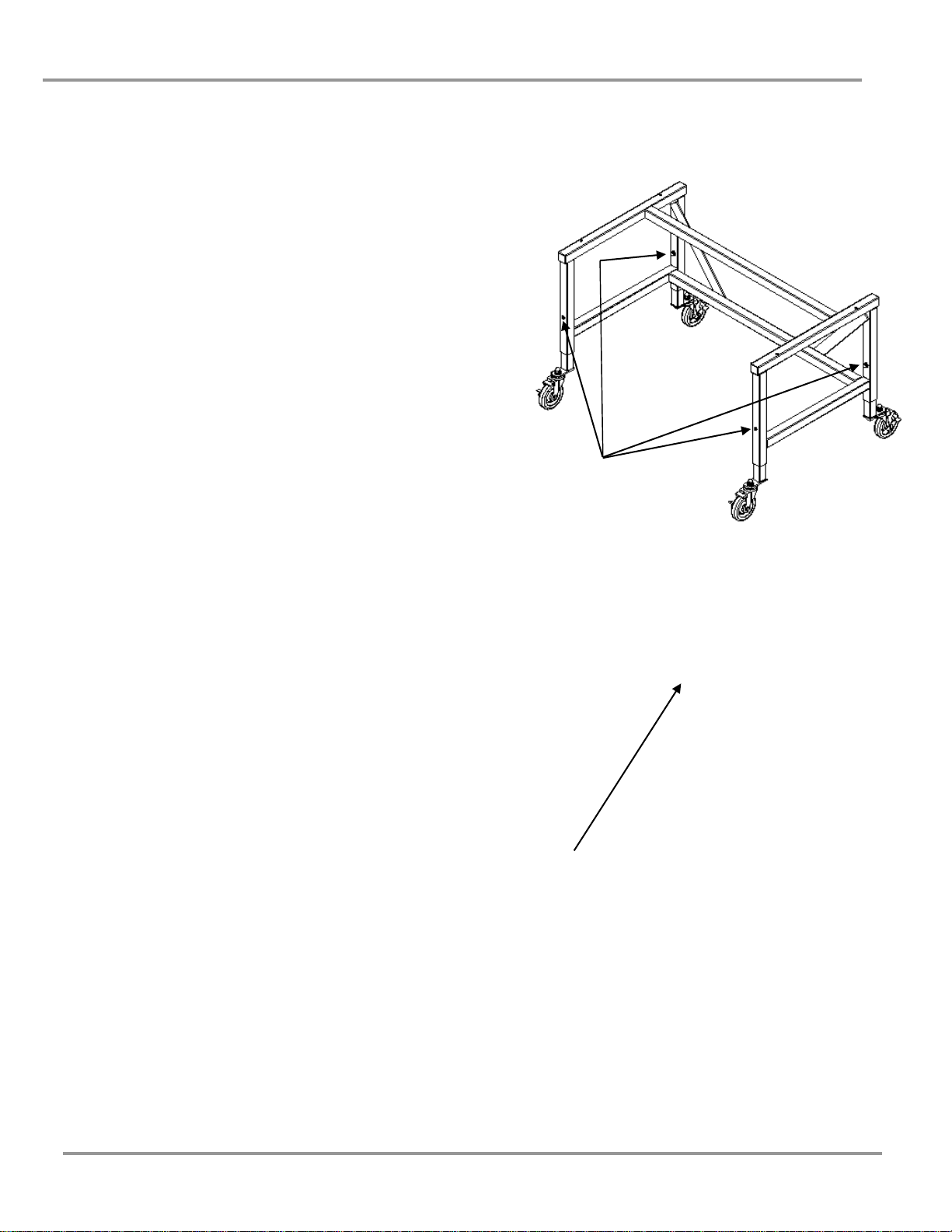
To change the height of the base stand,
remove these four nuts, washers and bolts
Install four bolts and flat
washers into base of cabinet
Stand and Cabinet Installation
1. The top surface of a base stand can be adjusted
from 27.5 to 34.50 inches (698mm to 876mm),
in 1 inch (25mm) increments. Choose your
optimum working height from the floor to the
work surface.
2. Slide (4) leg extensions into base stand corner
posts and attach with larger diameter 5/16"-18
x 2-1/4 inch (57mm) long bolt, flatwasher,
lockwasher and acorn nut. Ensure that the
same height hole is selected for each leg.
Tighten the leg bolts securely.
3. Move the base stand into its final location. For
stands with leveling feet, use a carpenter level
to adjust in both planes as shown in figure
below.
4. XPert Nano Enclosures have an integral
stainless steel work surface with mounting
holes on the underside. Hardware is provided
with the stand. Set the enclosure and work
surface onto the stand with the front edge of
the work surface flush (even) with the front
edge of the stand. Loosely attach each of the
four mounting locations of the work surface
with the smaller diameter 1/4"-20 x 2.5 inch
(63mm) long hex head bolts, nuts and washers.
Tighten when all four bolts have been started.
Product Service 1-800-522-7658
Page 16
Chapter 3: Getting Started
11
!
!
Connecting to the Exhaust System (Optional)
ATTENTION: The weight of the exhaust ductwork system
must be supported independently of the enclosure
superstructure or damage may occur.
The exhaust system should be installed by a qualified HVAC
contractor.
The exhaust connection on the 2', 3' and 4' XPert Nano Enclosure have been
designed to accept 6" diameter ductwork as shown in Figure 3-2. The 5' and 6'
models have been designed for 10" diameter ductwork as shown in Figure 3-3.
For the 2', 3' and 4' sizes, the exhaust connection ships uninstalled on the top and
needs to be fastened with the screws provided. See Chapter 7 for ordering Canopy
Exhaust Connection. Canopy Exhaust Connection aids in the removal of
chemicals or applications where a higher degree of powder and particulate removal
is required. Review Chapter 2 for exhaust prerequisites and review Chapter 7 for
ordering blower exhaust equipment.
Consult Labconco Customer Service should you require help sizing your blower
for the exhaust volume and system static pressure loss.
To ensure compatibility, the selected exhaust duct material
should match the enclosure, procedures and chemical
applications.
Product Service 1-800-522-7658
Page 17

Chapter 3: Getting Started
12
Figure 3-2
FOR 6" NOMINAL EXHAUST DUCT
CONNECTION 6.06" ID ON THE 2', 3' AND 4'
Product Service 1-800-522-7658
Page 18

13
Figure 3-3
10" NOMINAL ON THE 5' AND 6'
10.06" ID
Chapter 3: Getting Started
Product Service 1-800-522-7658
Page 19

Chapter 3: Getting Started
14
!
Connecting the Electrical Supply Source to the
Nano Enclosure
Simply connect the 115V power cord supplied to the IEC electrical supply plug on
the back of the enclosure. If using at 50 Hz operations, blower performance
maximum airflow will be reduced by 17%.
The same procedure applies for the 230V except it is shipped without a plug.
Install the appropriate plug for your electrical specifications per local codes. All
models use less than 5 amps.
All wiring for the XPert Nano Enclosure should be performed by a licensed
electrician and conform to local codes.
Do not use any detachable power cord that is not adequately rated
for the unit.
Ne pas utliser un fil électrique amovible qui n’est pas du tension
nominale de l’appareil.
Set the Face Velocity with the Speed Control Adjustment
Adjustment of the speed control gives the correct face velocity and is located behind
the front panel. The face velocity should be adjusted from 60 to 100 fpm. (Consult
your Safety Officer for airflow recommendations for your application). Containment is
maximized at a setting within this range. Working at the lowest face velocity
permissible for the application will give the least turbulent, quietest operation. Face
velocity measurements are made using an anemometer. An electric anemometer can be
obtained from your laboratory supply dealer.
To determine the actual face velocity at the sash opening, airflow velocity readings
are taken. This should be done across the sash opening of the enclosure in
accordance with the Industrial Ventilation Manual. (See Appendix E) The
“average face velocity” is achieved by taking readings in two rows across the
enclosure with the readings 6" from the ends and evenly spaced every 12"; the first
row is 3" down from the upper sash foil and the second row is 3" up from the work
surface. Refer to Chapter 2 for proper airflow volumes for your particular model.
The XPert enclosures have been tested at Labconco’s airflow test facility per
ASHRAE 110-1995. All enclosures achieve an “as manufactured rating” of less than
0.05 part per million (ppm) at 4 liters per minute (lpm); AM <0.05 (Consult
Labconco for individual ratings). For “field use” ASHRAE testing contact Labconco
for a certified on-site contractor. For particulate powder validation, Labconco
performed containment testing to validate the enclosures for sodium naproxen
powders. The XPert enclosures demonstrated excellent containment when used by an
operator using excellent technique and good containment when used by an operator
using marginal technique. While no enclosure can compensate for improper
technique, these tests confirm that the XPert Nano Enclosures provide a safe working
environment.
Product Service 1-800-522-7658
Page 20

Chapter 3: Getting Started
15
!
NOTE: Face velocity profiles and smoke testing should be performed
frequently per your organization’s quality system to ensure safe
performance.
Product Service 1-800-522-7658
Page 21

16
1
Chapter 4:
High Performance Features and
Safety Precautions
High Performance Features
The patented1 XPert Nano Enclosure is designed to meet the needs of the
laboratory scientist, and provide superior containment while conserving energy at
OSHA approved “low flow” velocities as low as 60 feet per minute. The filtered
enclosures have been tested to effectively contain toxic and noxious materials
when properly installed and operated. What makes the Labconco line of
enclosures so unique is the revolutionary way they direct air into and through the
contaminated air chamber. Labconco engineered them to minimize the effects of
turbulence. The containment-enhancing and aerodynamic designs of the upper
sash foil, side air foils, lower air foil, upper dilution air supply, and rear perforated
baffle all work in concert to produce horizontal airflow patterns that significantly
reduce powder, chemical and particulate concentrations through the work area.
These concentrations of materials are predominantly removed on the “first pass” of
airflow through the chamber resulting in high performance containment.
The plenum and the ULPA filter are jacketed by negative pressure. Should a leak
occur in the filter gasket or the plenum, the contaminated air is recaptured and
refiltered.
The XPert Nano Enclosure includes a true bag-in/bag-out ULPA filter disposal
system to protect the worker from contact with hazardous powders and
particulates. Users are encouraged to routinely check airflow with the use of the
airflow monitor.
U.S. Patent No. 6,461,233 and U.S. Patent No. D538,941
Product Service 1-800-522-7658
Page 22

Chapter 4: Performance Features and Safety Precautions
17
22
14
8
13
3 2 15
1 5 6
7
4
Not Shown 9, 10, 11, 12, 17, 18, 19, 20, 21, 23, 24
Figure 4-1
Product Service 1-800-522-7658
Page 23

Chapter 4: Performance Features and Safety Precautions
18
Figure 4-4
Figure 4-3
1. Aerodynamic Clean-Sweep™ Air Foil has a unique shape that allows air
to sweep the work surface for maximum containment. The Clean-Sweep™
openings create a constant protective barrier from contaminants. Should
the operator inadvertently block the airflow entering the air foil, air
continues to pass under the air foil and through the Clean-Sweep openings.
See Figures 4-1 and 4-3. The air foil is easily removable for cleaning. Do
not operate the enclosure without the air foil installed.
2. Containment-Enhancing Upper Sash Foil includes an open air passage
directly atop the sash foil to bleed air into the hood chamber and direct
chemical, powder and particulate materials away from the sash opening.
The radiused sash foil sweeps airflow into the hood with minimal
turbulence. See Figures 4-1 and 4-4.
Product Service 1-800-522-7658
Page 24

Chapter 4: Performance Features and Safety Precautions
19
3. Upper Dilution Air Supply provides bypass air from above the work area.
This feature constantly bathes the inside of the sash with clean air and
reduces powders, particulate materials and chemical fumes along the sash
plane, near the critical breathing zone. Five to seven percent of the
required air volume is introduced through the upper dilution air supply.
The upper dilution air supply also reduces stagnant pockets of air in the
upper interior.
4. Zoned Rear Perforated Baffle directs horizontal laminar air streams to
the three-zoned sections of the perforated baffle. The three-zoned sections
have increasingly more open area at the bottom that help form laminar
airflow. This minimizes the potential for air to roll forward preventing
contaminants from moving toward the sash opening. The majority of
contaminants are highly diluted, captured and removed on the first pass
through the enclosure. The rear perforated baffle may be tilted or removed
for ease in cleaning.
5. Side-Entry Air Foils allow turbulence-free air to enter the enclosure from
the sides and allow clean air to sweep the interior walls of the enclosure.
6. Safety Glass Sash has a wiping seal to contain contaminants and features a
spring-loaded latch to secure sash open for loading and cleaning. The sash
must be down for normal operation. The 5' and 6' units utilize a gas spring
assist in place of the latch.
7. Utility Ports allow electrical cords and data cords to pass through the back
of enclosure without leaving a large hole for contaminants to escape.
8. Accessory Guardian Airflow Monitor or Guardian™ 1000 Digital
Airflow Monitor continuously monitors airflow. An audio/visual alarm
alerts the user to low airflow conditions. The Guardian 1000 Digital
Airflow Monitor also displays a face velocity value, provides an RS232
output, a night setback mode and several auxiliary relay ports.
9. Inherently Safe Plenum has a negative pressure plenum that surrounds the
positive pressure impeller so that if a leak should occur, the unfiltered air is
captured and refiltered.
10. Vibration-Isolated Motorized Impeller has vibration isolation supports,
which eliminates transfer of vibration to the work surface. The impeller
wheel is also dynamically balanced.
11. Speed Control regulates the speed of the motorized impeller and is used
by the certifier to adjust the inflow velocity. Located behind the front
panel.
12. Fluorescent Lamp is located above the work area, out of contact with
contaminated air. A safety glass window beneath the lamp distributes the
light evenly across the work surface.
13. Filter System Pressure Gauge indicates the total system pressure across
the filter and pressurized plenum to help predict filter loading.
14. Filter Clamping Bolt evenly seals the filter to the frame of the enclosure.
Product Service 1-800-522-7658
Page 25

Chapter 4: Performance Features and Safety Precautions
20
15. ULPA Filter Access Port to access the ULPA filter during filter changing
procedures. For harmful powders and particulates, the true bag-in/bag-out
procedure is used to properly dispose of the contaminated ULPA filter.
16. Control Panel. The control panel, which is located above the sash,
contains the filter system pressure gauge, control switches and the
electronics.
17. ULPA (Ultra Low Penetration Air) Filter is rated to remove 99.999% of
all particles 0.12 micron in size.
18. Lamp Ballast (not shown) for the fluorescent lamp is located behind the
control panel.
19. Optional XPert Exhaust Collar (not shown) provides a 6" (2', 3' and 4')
or 10" (5' and 6') diameter transition to a remote blower or house exhaust
system.
20. Optional Accessory Canopy Exhaust Connection (not shown) is
available to duct the XPert Nano Enclosure to the outside. The Canopy
Exhaust Connection affords the operator additional protection from
hazardous particulates, fumes or vapors. Each Canopy Exhaust Connection
includes an epoxy-coated steel exhaust transition adapter designed for 6"
diameter nominal duct on 2', 3' and 4' sizes. The 5' and 6' sizes use 10"
nominal duct.
21. Optional Ionizer (not shown), when activated, floods the work area with
positive and negative ions to neutralize static charges on the surface of nonconductive items. Ionizer cannot be installed after manufacture.
22. Upper Diffuser Screen provides protection for the ULPA Filter and (LED)
airflow sensor. See Figure 4-1.
23. Optional Utility Shelves (not shown) allow the user to hold utensils and
printers on shelves inside the enclosure. See Chapter 7.
Safety Precautions
1. A qualified certification technician should test the enclosure before it is
initially used. The enclosure should be validated whenever it is relocated.
The use of an airflow monitor is recommended to alert the user to a
problem with airflow.
2. Use good housekeeping in the enclosure at all times. Clean up spills
immediately. Periodically clean enclosure interior.
3. Do not overload the work surface with apparatus or work material. The
safe operation of the enclosure is based upon having proper airflow through
the structure. Do not place large objects directly on the work surface.
Instead, elevate the object 3/4" on blocks to allow a flow of air under the
object and into the rear baffle exhaust slots.
Product Service 1-800-522-7658
Page 26

Chapter 4: Performance Features and Safety Precautions
21
4. Blocking large portions of the rear baffle will change the airflow pattern in
the enclosure causing turbulence. (Do not store containers or supplies
against the rear baffle.)
5. Always work far back into the enclosure as possible. Keep all powders,
chemicals and apparatus inside the lower air foil.
6. Perchloric acid use in this enclosure is prohibited.
7. Radioisotope materials are prohibited in this enclosure. Consult your
Safety Officer.
8. The enclosure should be recertified whenever it is serviced or at least
annually thereafter.
9. Use safety goggles, protective clothing, gloves and any other personal
protective equipment recommended by your safety officer.
10. The sash must remain in the down position while using the enclosure.
11. The ULPA filter provides personnel and environmental protection from
particulate matter. Because room air is drawn over the work surface during
operation, this enclosure should not be used for operations requiring
product protection from environmental contamination.
12. Avoid the use of flammable gases or solvents in the enclosure if possible.
Care must be taken to ensure against the concentration of flammable or
explosive gases or vapors. Use of an open flame should be avoided in the
enclosure as they may disrupt the airflow patterns in the cabinet. Gases
under high pressure should not be used in the enclosure as they may disrupt
the airflow patterns of the cabinet.
13. ULPA filters are only effective for entrapment of particulate matter.
Manipulations that generate gases or vapors from toxic chemicals or
radionuclides, must be evaluated carefully and vented in compliance with
applicable regulations.
14. The surface of the ULPA filter is fragile and should not be touched. Care
must be taken to avoid puncturing the filter during installation or normal
operation. If you suspect that a filter has been damaged DO NOT use the
enclosure; contact a local certification agency or Labconco.
15. The ULPA filter in the enclosure will gradually accumulate airborne
particulate matter from the room and from work performed in the
enclosure. The rate of accumulation will depend upon the cleanliness of
the room air, the operating time and the nature of work being done.
16. Ensure that the filtered enclosure is connected to an electrical service in
accordance with local and national electrical codes. Failure to do so may
create a fire or electrical hazard. Do not remove or service any electrical
components without first disconnecting the filtered enclosure from
electrical service.
Product Service 1-800-522-7658
Page 27

Chapter 4: Performance Features and Safety Precautions
22
17. Increase the face velocity by adjusting the speed control of the motorized
impeller on the XPert Nano Enclosure. Change the filter when the face
velocity falls below acceptable limits established by your Safety Officer.
18. Exhaust ULPA filters are disposed as hazardous waste. The user is
responsible for recording the material and disposing properly. Filters
should be disposed using the disposal bag on XPert enclosures.
19. Ensure only trained operators use the enclosure. New users should review
the User’s Manual and become familiar with the operation of the enclosure.
20. Proper operation of the enclosure depends largely upon the enclosure
location and the operator’s work habits. The enclosure should be located
away from traffic patterns, doors, fans, ventilation registers, fume hoods,
and any other air-handling device that could disrupt its airflow patterns (see
references in Appendix D).
21. For weighing procedures, adjust face velocity between 60 and 100 FPM for
effective operation.
22. Leave the blower on for at least one minute after work in the enclosure has
been completed.
23. If a chemical, powder or particulates are spilled on the work surface, DO
NOT switch off the blower until all traces have been removed.
24. Tag enclosures with appropriate warning, if the enclosure has been disabled
for service.
25. If the blower fails during use, processes should cease and the area should
be vacated and ventilated.
Product Service 1-800-522-7658
Page 28

23
Chapter 5:
Using the Nano Enclosure
Now that the installation of your Nano enclosure is completed, you are ready to
use your Nano enclosure.
Read this chapter to learn about:
Routine Daily Work Procedures
Appropriate ULPA Filter Applications, Suitability and Guidelines
Optional Ionizer
Prohibited Acid Use
Routine Daily Work Procedures
Planning
Arrange for minimal disruptions, such as room traffic or entry into the
room while the enclosure is in use.
Start-up
Turn on exhaust system and light.
Only raise the sash for loading and cleaning.
Check the baffle air slots for obstructions.
Allow the enclosure to operate unobstructed for 1 minute.
Wear a long sleeved lab coat and rubber gloves. Use protective eyewear.
Wear a protective mask if appropriate. Consult your Safety Officer for
additional personal protective equipment recommendations.
Loading Materials and Equipment
Load only the materials required for the procedure. Do not overload the
enclosure.
Do not obstruct the air foil, or rear baffle slots.
Large objects should not be placed close together and should be elevated
above the work surface to permit airflow to sweep under the equipment.
After loading, wait one minute to purge airborne contaminants from the
work area.
Product Service 1-800-522-7658
Page 29

Chapter 5: Using the Nano Enclosure
24
Work Techniques
Keep all materials inside the lower air foil, and perform all contaminated
operations as far to the rear of the work area as possible.
Segregate all clean and contaminated materials in the work area.
Avoid using techniques or procedures that disrupt the airflow patterns of
the enclosure.
Final Purging
Upon completion of work, the enclosure should be allowed to operate for
two to three minutes undisturbed, to purge airborne contaminants from the
work area before shutting down the blower.
Unloading Materials and Equipment
Objects in contact with contaminated material should be surface
decontaminated before removal from the enclosure.
All open trays, weigh vessels or containers should be covered before being
removed from the enclosure.
Shutdown
Turn off the exhaust system and light.
ULPA Filter Applications, Suitability and Guidelines
Weighing and handling of powders.
Release of nonvolatile particulates appropriate for use with a ULPA filter.
The ULPA filtered enclosure provides personal and environmental protection
from particulate matter, hazardous powders and biohazardous materials.
Because room air is drawn through the enclosure during operation, this
enclosure should not be used for operations requiring sample protection from
environmental contamination.
ULPA filters are only effective for entrapment of particulate matter, hazardous
powders and biohazardous materials. Manipulations that generate gases or
vapors, i.e., toxic chemicals or radionuclides, require ventilation to the outside of
the building. The surface of the filter is fragile and should not be touched. Care
must be taken to avoid puncturing the ULPA filter during installation. If you
suspect that a ULPA filter has been damaged, DO NOT use the enclosure. See
Chapter 6 for replacing the ULPA Filter or using a Bag-In/Bag-Out Disposal Bag.
The ULPA filter will gradually accumulate airborne particulate matter from
the room and from work performed in the enclosure. The rate of accumulation
will depend upon the cleanliness of the room air, the operating time, and the
nature of work being performed.
Each Nano Enclosure is provided with a ULPA filter. For powders and
particulates follow the ULPA Filter Bag-In/Bag-Out procedure in Chapter 6
for disposal instructions. For biohazardous materials, follow the
Decontamination Procedure in Chapter 6 for disposal instructions.
Product Service 1-800-522-7658
Page 30

Chapter 5: Using the Nano Enclosure
25
!
Optional Ionizer
The XPert Nano’s optional built-in ionizer is designed to control static charge on
surfaces within the enclosure. The discharge of the ionizer is uniquely located at
the front face of the work surface, safe from the contaminants and cleaning within.
The emitters within the ionizer have a finite life and therefore there may be times
when one might choose to use the enclosure with the ionizer OFF. The
Blower/Ionizer control switch allows the blower to be operated independently of
the ionizer. Push the top of the switch to activate the blower only; push the bottom
to energize the ionizer along with the blower. The green light adjacent to the
ionizer emitters (on the face of the work surface) will illuminate when the ionizer
is active.
Refer to the Maintenance section of this User’s Manual to keep the ionizer
working at its full potential. Cleaning of the emitter points is recommended every
two to three months (based on 8-hr daily operation).
ATTENTION: NEVER operate the enclosure in an explosive
environment. The ionizer may cause detonation. NEVER
operate the ionizer without the emitter points installed; damage
will occur.
Product Service 1-800-522-7658
Page 31

Chapter 5: Using the Nano Enclosure
26
Prohibited Acid Use
The XPert Nano Enclosure motorized impeller and stainless steel interior should
not be exposed to acids. Where applications require the use of acids, a separate
ventilated enclosure or vented fume hood should be used with a remote blower
ducted to the outside.
No exceptions are permitted, as the impeller life span will be limited with acid use.
Product Service 1-800-522-7658
Page 32

27
Chapter 6:
Maintaining the Nano Enclosure
Monitoring airflow and changing the filters is the primary maintenance required.
Decontamination may be required and is reviewed in this chapter.
Review this chapter on maintenance for the following:
Routine Maintenance.
Decontamination.
Determination of when to replace the ULPA filter(s).
How to install a new ULPA filter with the bag-in/bag-out procedure.
Filter leak test.
Speed control adjustment and setting the inflow face velocity.
Operating and calibrating the airflow monitors.
Initial certification.
Re-certification.
Fluorescent light replacement.
Motorized impeller replacement.
Speed control replacement.
Maintenance on the Optional Ionizer.
Routine Maintenance Schedule
Weekly
Wipe down the interior surfaces of the enclosure with a disinfectant or
cleaner, depending upon the application.
Using a damp cloth, clean the exterior surfaces of the enclosure,
particularly the front and top to remove any accumulated dust.
Operate the exhaust system, noting the airflow velocity through the
enclosure using a source of visible smoke. Airflow monitors are
recommended for constant monitoring.
Product Service 1-800-522-7658
Page 33

Chapter 6: Maintaining the Nano Enclosure
28
Monthly (or more often as required)
Determine the actual face velocity through the sash opening of the
enclosure where the average reading should be at the specified velocity.
(Use calibrated thermal anemometer or other approved apparatus). Airflow
alarms are recommended for constant monitoring.
The enclosure rear baffle should be checked for any blockage to ensure that
the enclosure is maintaining proper airflow.
All weekly activities.
Check face velocity. Increase speed control or change ULPA filter when
face velocity of the enclosure drops below the recommended speed for your
facility or if the airflow alarm monitor alerts you. Airflow monitors are
recommended.
If equipped with optional Ionizer, clean and inspect emitter points.
Annually
Replace the fluorescent lamps.
Have the enclosure validated by a qualified certification technician. See
Certification and Recertification in this chapter.
All monthly activities.
Decontamination
When used in conjunction with biohazards, the XPert Nano Enclosure should be
decontaminated with formaldehyde gas before:
Maintenance work in contaminated areas
Filter changes
Moving the cabinet to a new location
Changing research programs
After a gross spill of biohazardous material
The procedures for performing a gaseous decontamination are thoroughly outlined
in the U.S. Department of Health, Education and Welfare booklet entitled
Formaldehyde Decontamination of Laminar Flow Biological Safety Cabinets,
available from NIH, Division of Safety, Bethesda, MD 20892, call 301-496-2801,
or from Labconco Corporation.
Determination of When to Replace ULPA Filters
The ULPA filters in the filtered enclosures gradually accumulate airborne
particulate matter and powders from the enclosure and room. Replace filter(s)
when face velocity drops below the recommended 60-80 fpm velocity, and the
speed control is adjusted to full speed. Replace ULPA filter(s) if it fails the Filter
Leak Test in this chapter.
Product Service 1-800-522-7658
Page 34

Chapter 6: Maintaining the Nano Enclosure
29
!
How to Install a New ULPA Filter with the BagIn/Bag-Out Procedure
The XPert line of enclosures include a true bag-in/bag-out filter disposal system
for safely removing the ULPA filter and protect the worker from toxic powders
and particulates. See Figures 6-1 for the Bag-In/Bag-Out Procedure. For your
safety, wear appropriate personal protective equipment during the change of filters.
If working with biohazardous materials, use the decontamination procedure
outlined in this chapter. (Consult your Safety Officer before performing filter
changes).
Do NOT contact blower wheel while still in motion.
NE PAS être en contact avec la roué du ventilateur tant qu’il est
en marche.
1. With the enclosure OFF, remove the front panel secured by two screws on
top of the enclosure.
2. Remove the bungee cords and retaining strap on the bag and extend it out.
The retaining strap provides an extra level of safety even though the
enclosure is under negative pressure when the blower is on.
3. Loosen the two filter clamp bolts with a 9/16" socket securing the ULPA
filter. See Figure 4-1.
4. Place both arms in the rear gloves of the bag, and carefully draw the ULPA
filter out of the enclosure. Rest the filter on the floor, table or cart.
Remove arms from bag gloves.
5. Create two seals between the enclosure bag access port and the old filter.
Seals can be heat sealed or sealed with tie wraps. Cut off the bag between
the two seals and leave the bag stub on the access port to the enclosure.
6. Place the new ULPA filter in the new bag. Then place the new bag and
new filter over the old bag stub and onto the enclosure access port.
7. Carefully remove the old bag stub using the single glove near the access
port. Reattach the retaining strap on the perimeter of the new bag at the
enclosure access port. Draw the old bag stub into the single glove and turn
the glove inside out. Double seal this glove and cut off the glove with the
contaminated bag stub inside.
8. Carefully install the new ULPA filter and uniformly tighten the two filter
clamp bolts until the filter gasket is compressed 50%.
9. Carefully fold and roll the new bag in four-inch pleats and push the bag
into the access port. Reinstall the retaining strap and bungee cords. Turn
the enclosure ON to draw a vacuum on the bag. Reinstall the front panel.
Product Service 1-800-522-7658
Page 35

Chapter 6: Maintaining the Nano Enclosure
30
Old Filter
New Filter
Old ULPA Filter Sealed in Old Bag
Filter Gasket Up As Shown
Filter Gasket Up As Shown
Create Two Seals & Cut Here After Sealing
Bag Stub from Old Bag
Clip to Hold Perforated Cover
Perforated Top Cover
Screw (One Each Side)
Speed Control Adjustment
Screw Location
Create Two Seals & Cut Here After Sealing
Old Bag Stub Sealed in Glove of New Bag
New ULPA Filter Shown in New Bag
Figure 6-1
Bag-In/Bag-Out Filter Changing Procedure Diagram
& Filter Leak Test Diagram
Filter Leak Test
Purpose
After installing the new ULPA filter, the filter should be leak checked. This test is
performed to determine the integrity of the ULPA filter, the filter housing, and the
filter mounting frames. Leak testing is to be done by a qualified technician with
calibrated equipment. Remove the top perforated exhaust cover by using a Phillips
screwdriver to unfasten the (2) screws used to secure (2) clips. See Figure 6-1. The
filter passes the leak test at .01% or better. Reference Leak Testing and Photometer
scanning from the Institute of Environmental Services (IES-RP-CC001.3)
Apparatus
1. An aerosol photometer ATI model 2D, 2E, 2G or equivalent. Air
Techniques Hamilton Associates Inc., 11403 Cronridge Dr., Owings Mills,
MD 21117
Product Service 1-800-522-7658
Page 36

Chapter 6: Maintaining the Nano Enclosure
31
2. One aerosol generator of the Laskin nozzle(s) type. An aerosol of mineral
oil or suitable liquid shall be created by flowing air through it. The compressed
air supplied to the generator should be adjusted to a pressure of 10± 1 psig
during operation. Air Techniques Inc. Model TDA-4A or equal. One nozzle at
10 psig is (67.5 cfm x 100ug/l)/(Vol. of air), For the 2' at 90 fpm or 130 cfm,
one nozzle @10 psig is 6,750/130 cfm = 52 ug/l. For the 3' at 90 fpm or 200
cfm, one nozzle @ 10 psig is 34 ug/l. For the 4' at 90 fpm or 265 cfm, one
nozzle at 10 psig is 26 ug/l. For the 5' at 90 fpm or 215 cfm, one nozzle at 10
psig is 31 ug/l. For the 6' at 90 fpm or 260 cfm, one nozzle at 10 psig is 26
ug/l. Note 5' and 6' use two filters.
3. Mineral oil (Catalog #1491400).
4. Sampling Nozzle, Rectangular 1/2" x 3-1/4", Air Techniques, Inc.
Procedure
For the ATI 2G Photometer
1. Turn on the photometer and allow it to operate for a minimum of 5 minutes.
Leave the valve in the “CLEAR” setting.
2. Press the “ENTER” keypad. Press the “REF” keypad.
3. The display will display “P1” for approximately 1 second, and then display a
numerical value.
4. Using the “^” or “ν” keypads, respectively, increase or decrease the numerical
value until it equals 52 (2'), 34 (3'), 26 (4'), 31 (5'), 26 (6') for the enclosure at
90 fpm inflow velocity.
5. Press the “ENTER” Keypad. The photometer will scan for 15 seconds, and
then the “0” keypad will flash. Press the “Enter” keypad. The unit will scan for
5 seconds, the display will read “0000,” and the unit will sound a confirming
tone.
6. Set the valve to “DOWNSTREAM.” Place the palm of your hand over the
sampling port of the pistol. There should be a strong vacuum at this port. If the
vacuum is weak, contact Air Techniques Hamilton Associates.
7. Turn the enclosure on and let it operate for a minimum of 5 minutes.
8. If necessary, adjust the speed control of the enclosure to maintain the following
airflows at 90 fpm; 2' (130cfm), 3' (200 cfm, 4' (265 cfm.), 5' (215 cfm), 6'
(260 cfm). The 5' and 6' uses two filters.
9. Position the aerosol generator discharge in the intake of the baffle inside the
enclosure.
10. Start the aerosol generator (Pressure to be +/- 1 psig). (10 psig). Ensure that
one Laskin nozzle is in the “open” position.
Product Service 1-800-522-7658
Page 37

Chapter 6: Maintaining the Nano Enclosure
32
11. Allow the generator to operate for a minimum of 15 seconds. For all integral
motorized impeller models, scan the downstream exhaust side of the filter by
passing the sampling nozzle of the gun in slightly overlapping strokes over the
entire surface the filter, with the sampling port not more than 1 inch from the
surface of the filter media. Scan the entire periphery of the filter and the gasket
between the filter frame and the enclosure frame. Scanning shall be done at a
traverse rate of not more than 2 inches per second.
NOTE: For duct connected Nano Enclosures, place the sampling nozzle in
the center of the remote blower exhaust.
Acceptance
Aerosol penetration shall not exceed 0.01 percent measured by the photometer.
Setting the Inflow Face Velocity with the Speed
Control Adjustment
1. Remove the front panel by loosening the (2) Phillips screws on top that
secure the front panel.
2. The speed control is located on the electrical subassembly located behind
the switched control panel and below the front panel. See Figure 6-1.
3. Adjust the speed control with a small Phillips screwdriver by turning the
screw counterclockwise to increase blower speed or clockwise to decrease the
blower speed. The speed control is very sensitive, so proceed with caution.
4. Measure the inflow velocity per the averaging technique outlined in Chapter
3 and adjust the speed control slowly for the desired speed. Allow the speed
to stabilize and re-measure the inflow velocity to confirm.
5. Replace the front panel and tighten the screws.
Calibrate and Operate the Airflow Monitors
Labconco Airflow Monitor/Airflow Switch Operation:
The Guardian Airflow Monitor (LED) consists of a circuit board and an airflow
switch. This switch indicates airflow as safe or low. It does not provide an actual
face velocity, but a small setscrew in the back of the sensor can adjust the airflow
level that it classifies as “good/safe” or “low/alert.”
The circuit board provides power to the sensor and also contains a “safe (green)”
and “alert (red)” airflow LED indicators, as well as a “SILENCE ALARM” button
to quiet the audio alarm. When first powered up, the PCB will light both red and
green LED indicators and sound the alarm to indicate it is working. After 5
seconds, the air monitor will indicate either good or bad airflow based on what the
connected airflow switch detects. For low airflow, the unit will wait for 10 seconds
of bad indications before it sounds both the audio alarm and the red “alert” LED
indicator. If the “SILENCE ALARM” button is pressed, the audio alarm will be
silenced, but the red “alert” LED will remain on. The alarm is silenced indefinitely
Product Service 1-800-522-7658
Page 38

Chapter 6: Maintaining the Nano Enclosure
33
unless an airflow change is detected. If safe airflow is later detected for 10 seconds,
the green “safe” LED will be lit and the “alert” (red) LED will be shut off. At any
time the airflow is safe/good, one can press the SILENCE ALARM test button and
the audio alarm and the red LED will turn on as long as this button is held down.
The circuit board has also a two-pin connector for use as an external output with
isolated relay contacts that close when the red/alert LED is lit (low airflow). These
relay contacts are not affected by the “SILENCE ALARM” button.
The circuit board is mounted behind the front panel using standoffs and an
appropriate label is used to highlight the “SILENCE ALARM” button with clear
areas for the red and green LED’s. No holes to allow sound to be broadcast louder
are necessary.
The circuit board can be prepared as a factory special with an additional connector
for the following external inputs, and having the following possible functions:
External Alarm allows an external signal to sound the alarm, such as a sash
open switch, or a “fail” signal from the building airflow system.
Alarm Disable allows an external signal to prevent a “low” airflow alarm from
occurring.
Contact Labconco for ordering information on this special circuit board.
Calibration
1. Ensure the flow switch and alarm circuit board are installed and
operational.
2. Allow the enclosure to operate for at least two minutes.
3. If factory installed, the monitor will alarm at 60±10 fpm with the inflow
velocity set at 90±10 fpm.
4. To change the factory setting, set the inflow velocity required by your
Safety Officer to the desired alarm condition using the speed control
adjustment procedure outlined in Chapter 6.
5. Once the alarm condition is set, use a small screwdriver to turn the
adjustment screw on the airflow switch counterclockwise (facing the
screw) until the “low” airflow red LED lights and the audible flow alarm
sounds.
6. Adjust the inflow velocity to the nominal operating point required by your
Safety Officer.
7. Over time the ULPA filter will load and eventually slow the inflow
velocity. Once the alarm condition is met, simply increase the speed
control outlined in Chapter 6 or replace the ULPA filter if the speed control
is maximized.
Product Service 1-800-522-7658
Page 39

Chapter 6: Maintaining the Nano Enclosure
34
Enclosure Operating In-Flow
Speed
Alarm Condition Set Point
Speed
100 ± 10 fpm
70-90 fpm
90 ± 10 fpm
60-80 fpm
80 ± 10 fpm
50-70 fpm
70 ± 10 fpm
50-60 fpm
60 ± 10 fpm
50 fpm
8. The table below lists typical alarm conditions based on normal operating
conditions. Typical alarm conditions are set at face velocities of 10 to 30
feet per minute below the normal operating conditions due to supply air
and exhaust air fluctuations, as well as room air cross drafts. Consult your
Safety Officer for proper operating speeds.
Figure 6-2
Guardian Airflow Monitor (LED) with Airflow Switch
Product Service 1-800-522-7658
Page 40

Chapter 6: Maintaining the Nano Enclosure
35
Guardian Digital 1000 Airflow Monitor
Option
Refer to Figure 6-3 for operation and calibration. Refer to the separate Labconco
1000 Alarm Manual for detailed information.
Operation
The Guardian Digital Airflow Monitor consists of the airflow sensor, the Alarm
Unit, and the 15 VDC power supply. For 115V operation the alarm unit is
powered by plugging the power supply into the factory-prepared digital airflow
monitor socket. For 230V operation, the Alarm Unit is powered by plugging the
power supply into a building outlet. The alarm has “Enter,” “+,” and “-” buttons to
program the monitor. There is also a green LED “SAFE,” yellow LED
“CAUTION,” and red LED “LOW” with audible alarm for airflow conditions.
The audible alarm can be permanently muted if desired. The Guardian Digital
1000 Airflow Monitor displays a face velocity value, provides an RS232
communications port to a PC or building computer system, can be configured for
external input connections such as night setback or external alarm and provides up
to three output relays that can be configured. For complete detailed information,
please refer to the separate Labconco 1000 Alarm User’s Manual provided with
the enclosure.
Digital 1000 Calibration
The filtered enclosure comes factory calibrated with the monitor alarm at 60 ± 10
fpm with the inflow velocity set at 90± 10 fpm.
Programming the Guardian 1000 Digital Alarm
Set the desired face velocity of the enclosure with the sash in the down position
using an average face velocity of readings from a thermal anemometer.
a. 2 ft enclosure – 2 readings
b. 3 ft enclosure – 3 readings
c. 4 ft enclosure – 4 readings
Configure Alarm
To successfully calibrate the airflow monitor, it will be necessary to change the
face velocity by adjusting the airflow exhaust volume. The exhaust volume can be
adjusted using the speed control located behind the front panel on the XPert Nano
Enclosure. For XPert Nano Enclosures that are ducted to a roof blower, the
exhaust volume is adjusted through a damper in the building exhaust system.
The following inflow face velocity speeds are recommended to successfully
calibrate. To begin, determine what the low airflow, low warning airflow, normal
airflow, and high airflow shall be.
Product Service 1-800-522-7658
Page 41

Chapter 6: Maintaining the Nano Enclosure
36
Low Air Alarm
Set Point
(user defined)
Enclosure
Operating
Inflow Speed
Low Calibration
Set Point
(user defined)
High Calibration
Set Point
(user defined)
40 – 50 fpm
60 fpm
40 – 60 fpm
100 – 120 fpm
60 – 70 fpm
80 fpm
50 – 90 fpm
100 – 150 fpm
80 - 90 fpm
100 fpm
50 – 110 fpm
100 – 170 fpm
CALIBRATION CONFIG MENU
SETTINGS
DISPLAY UNITS
FPM
LOW AIR ALARM
SEE CHART ABOVE – LOW AIR ALARM
LOW AIR CUTOFF
OFF
LOW AIR CUTOFF
SEE CHART ABOVE – LOW AIR ALARM
WARNING AIR ALARM
SEE CHART ABOVE – LOW CALIBRATION SET
POINT (Set 3-5 FPM above low air alarm)
WARNING AIR RESET
3 FPM
HIGH AIR ALARM
OFF
HIGH AIR ALARM
OFF
LOWER AIR SAMPLE FLUCTUATIONS
3%
HIGHER AIR SAMPLE FLUCTUATIONS
3%
LOWER/HIGHER AIR SAMPLE
DIFFERENCE
10 FPM
WARN TO ALARM AIR TIME
10 SECONDS
ALARM TO WARN AIR TIME
3 SECONDS
SHOW AIR FLOW
ON
SHOW TIME LINE OFF = DISPLAYS
BAR GRAPH
OFF
AUDIBLE ALARM
ENABLED
SENSOR DIFFERENCE
2%
NOTE: ENTER button stores information
+/- Buttons allow for scrolling.
1. Push the ENTER button on the face of the alarm until the Set up Menu is
displayed.
2. Scroll to SET UP and hit ENTER.
3. The PASSWORD MENU displays (The Password is 0000). Press the
ENTER button repeatedly until the CAL CONFIG MENU is displayed.
4. In the CAL CONFIG MENU set for the following:
5. To complete the CAL CONFIG, be sure to enter “DONE”. You are
returned to the Main Menu.
Product Service 1-800-522-7658
Page 42

Chapter 6: Maintaining the Nano Enclosure
37
Calibrate Alarm
1. Scroll to set up and hit ENTER, then CALIBRATE and hit ENTER.
2. The PASSWORD MENU displays (The Password is 0000). Press the
ENTER button repeatedly until the next menu is displayed.
3. Adjust the speed of the fan until the low airflow velocity is reached. Use
your thermal anemometer readings to determine the low air velocity.
4. Enter the value of your low airflow velocity using your +/- scroll keys. Be
sure the front panel is installed. Step out of the way, wait approximately 30
seconds for air currents to settle and hit ENTER. The airflow alarm will
sample the airflow.
5. Adjust the speed of the fan until the high airflow velocity is reached using
the readings from the thermal anemometer. Then re-install the front panel,
if so equipped.
6. Enter the value of your high airflow velocities. Be sure the front panel is
installed. Step out of the way, wait approximately 30 seconds for air
currents to settle and hit ENTER. The airflow alarm will sample the
airflow.
7. The set up menu is displayed. Select DONE and hit ENTER.
8. The main menu will be displayed. Select RUN and hit ENTER.
You have successfully configured and calibrated your Guardian 1000 Digital
Airflow Monitor.
Product Service 1-800-522-7658
Page 43

Chapter 6: Maintaining the Nano Enclosure
38
Figure 6-3
Guardian Digital 1000 Airflow Monitor
Product Service 1-800-522-7658
Page 44

Chapter 6: Maintaining the Nano Enclosure
39
Initial Certification
The filtered enclosure has been certified at the factory for an inflow velocity of
90±10 fpm along with the Filter Leak Test. The filtered enclosure should be
certified for the proper inflow velocity required by your Safety Officer. It is also a
conservative recommendation to perform the Filter Leak Test again should there
be any damage caused during transport.
Re-Certification
Under normal operating conditions, the enclosure should be recertified at least
annually if serviced. The certifier should perform the following tests.
Inflow Velocity Test
ULPA Filter Leak Test
In addition, the following tests should also be performed at the user’s discretion:
Measure of Line Voltage and Current
Smoke Test to determine proper airflow patterns
Lighting Intensity Test (when appropriate)
Noise Level Test (when appropriate)
Vibration Test (when appropriate)
Fluorescent Light Replacement
1. Disconnect the power.
2. Locate the small light reflector located under the control panel shown in
Figure 6-2 and Figure 6-3.
3. Remove the light reflector support by removing two Phillips screws on the
bottom of the light reflector.
4. Rotate and remove the old fluorescent lamp.
5. Reinstall the new fluorescent lamp and light reflector in reverse order.
6. Power the unit up and try the new fluorescent lamp.
Product Service 1-800-522-7658
Page 45

Chapter 6: Maintaining the Nano Enclosure
40
!
!
Motorized Impeller Replacement
The motorized impeller must be replaced as a complete unit. When the motorized
impeller is replaced, the capacitor may also be replaced. See Appendix A for
Replacement Parts Diagram. See Figure 6-5 for an isometric view of the motorized
impeller plenum assembly. The ULPA filter rests on top of the motorized impeller
assembly.
Do NOT contact blower wheel while still in motion.
NE PAS être en contact avec la roué du ventilateur tant qu’il est
en marche.
1. Wear appropriate personal protective equipment to decontaminate the filtered
enclosure and then unplug from the electrical outlet.
2. Remove filter per the ULPA filter removal procedure outlined in this chapter.
3. Consult the wiring diagram in Appendix C of the manual and disconnect all the
wires of the motorized impeller. Be sure to connect wires on the new motor in
the same way the old motor was wired. If contaminated with chemicals,
neutralize the old motor by submersion in an appropriate solvent. Bag and
dispose of the old motor responsibly.
4. Remove four screws in the motor bracket that hold motor bracket to the
supports with the vibration isolation mounts. Remove the motor and bracket.
ATTENTION: High-speed blower. Never operate impeller with
housing off.
5. Replace the capacitor with a new one of equal voltage and capacity.
6. Reassemble the new motorized impeller by reversing the assembly steps.
Product Service 1-800-522-7658
Page 46

Chapter 6: Maintaining the Nano Enclosure
41
Filter Gasket Up
ULPA Filter
Screws to Remove (2 Each Side)
Vibration Isolator Mount
ULPA Filter Back Stop
Motorized Impeller
Impeller Metric Screws & Washers
Motorized Impeller Plenum Assembly
Motor Support Bracket
Wire Access Hole
Wire Access Hole
!
Figure 6-4
Motorized Impeller Replacement
Speed Control Replacement
Do NOT contact blower wheel while still in motion.
NE PAS être en contact avec la roué du ventilateur tant qu’il est
en marche.
1. Remove the bracket that the speed control is attached to. See Figures 6-1, 6-2
and 6-3.
2. Remove the two screws holding the speed control using a Phillips screwdriver.
Refer to Appendix A for Replacement Parts Diagram.
3. Disconnect all wires leading to the speed control. Connect wires on new speed
control in the same position as the old speed control.
4. Reassemble to the system in the same position and with the same screws that
were removed earlier.
Product Service 1-800-522-7658
Page 47

Chapter 6: Maintaining the Nano Enclosure
42
!
Maintenance on the Optional Ionizer
Occasional cleaning of the ionizer’s emitter points is the only routine maintenance
required. Regularly scheduled cleaning extends the life of the unit and sustains the
delivery of ionized air. Clean the emitter points every 60 to 90 days (based on 8-hr
daily operation).
Emitter Point Cleaning
NOTE: Disconnect power to the XPert Nano Enclosure at least
one minute before performing cleaning or replacement of the
Ionizer Emitter Points. The ionizer has a high voltage power
supply that must discharge over that one minute time period.
Emitter points are better cleaned without removal. Use a clean room compatible
(non-shedding) swab moistened with the following solution to gently wipe the
points.
Cleaning solution of 50% IPA (laboratory or electronic grade
isopropyl alcohol and 50% de-ionized water).
Emitter Point Replacement
If the ionizer fails to neutralize charges in the airstream, the only portions of the
ionizer that can be serviced are the emitter points. Do not attempt to disassemble
the ionizer bar located under the work surface. A surface static charge meter is
required to test the ionizer’s effectiveness. Apply a static charge to a piece of
plastic with a synthetic fabric and measure the voltage at the surface before and
after placing it in the airstream with the ionizer ON.
Ionizer Emitter Points Part Number 3884300
Emitter points may require replacement in two to three years or when erosion or
damage is evident. To replace the points:
1. Remove power to the unit for at least one minute
2. Grasp each emitter point with a small needle nose pliers and pull them
out of their socket
3. Install the replacement point with care. Using the needle nose pliers
and gripping the emitter away from the sharp point.
4. Follow the Emitter Point Cleaning instructions above before use.
Product Service 1-800-522-7658
Page 48

Chapter 6: Maintaining the Nano Enclosure
43
Upper Diffuser
Trace Odor
Airflow Sensor
Trace Odor Carbon Filter Installation
In the event that low volumes of solvents are required, a Trace Odor Carbon Filter
can be installed.
1. Remove the screws (2) located on each side of the upper diffuser.
2. Lift and remove the upper diffuser.
3. Place the Trace Odor Carbon Filter on top of the HEPA filter with the gasket-
side DOWN. Use care when maneuvering past the airflow sensor. Be careful
not to harm the HEPA filter media that is exposed.
4. Replace the upper diffuser.
5. Replace all screws.
Carbon Filter
Product Service 1-800-522-7658
Page 49

44
Description
Order Part #’s
Individual Parts Required
Guardian Airflow Monitor
115V or 230V
1 ea.
3811500
Airflow Monitor Printed Circuit Board
1 ea.
3910700
Airflow Sensor w/ Connector
2 ea.
1885405
#6-32 x .31" Phillips machine screw to
mount Airflow Monitor Circuit Board
2 ea.
1891808
#6-32 x .50" Phillips thread cutting screw to
mount Airflow Sensor
Guardian Digital 1000
Airflow Monitor
115V 1 ea.
3908500
115V Guardian Digital Monitor, Airflow
Sensor, Sensor Cable, and 15 VDC power
supply
230V 1 ea.
3908501
230V Guardian Digital Monitor, Airflow
Sensor, Sensor Cable, and 15 VDC power
supply
1 ea.
3904803
2' Front Panel w/ cutout
or
1 ea.
3904804
3' Front Panel w/ cutout
or
1 ea.
3904805
4' Front Panel w/ cutout
Chapter 7:
Accessorizing the Nano
Enclosure
There are several ways to accessorize and modify the filtered enclosure for your
individual requirements. These include the addition of airflow monitors; exhaust
transition kits, remote blowers, exhaust dampers, filters, storage cabinets and
utility shelf kit.
1. Guardian™ 1000 Digital Airflow Monitor or Guardian™ LED
Airflow Monitor
The Guardian Digital 1000 Airflow Monitor or Guardian LED Airflow
Monitor allows you to continuously monitor airflow through the enclosure.
Either monitor is usually provided with the XPert enclosures.
Add appropriate Front Panel with cutout to mount Digital 1000 Airflow
Monitor
Product Service 1-800-522-7658
Page 50

45
Part
Description
3924400
2' Canopy Exhaust Connection (6")
3924401
3' Canopy Exhaust Connection (6")
3924402
4' Canopy Exhaust Connection (6")
3924403
5' Canopy Exhaust Connection (10")
3924404
6' Canopy Exhaust Connection (10")
CFM @ Static Pressure-Inches of H2O
S.P.
0.0"
0.125"
0.25"
0.50"
0.75"
0.87"
CFM
595
560
515
420
300
167
Catalog
#
Description
Shipping Wt.
(lbs/kg)
4863500
Remote Blower, 115 V, 60 Hz. 4.4 amps
35/16
4863501
Remote Blower, 115/230 V, 50 Hz, 5.6/2.8 amps
35/16
7053501
Explosion-Proof Remote Blower, 115 V, 60 Hz,
4.4 amps
40/18
NOTE: The cutout can also be made with a reciprocating saw and a 1/8" diameter
bit. The centerline of the cutout is located 3.3" from the left side and 4.2"
from the bottom. The 1/8" mounting holes are spaced 4.38" apart top to
bottom and centered over the cutout. The cutout dimensions are 2.43"
wide by 4.13" tall.
2. Canopy Exhaust Connection for Ducting to Outside
Chapter 7: Accessorizing the Nano Enclosure
Canopy Exhaust connects to the filtered enclosure with integral motorized
impellers from the top so the duct can be routed up and outside the building.
The Canopy Exhaust is available for 6" nominal duct on 2', 3' and 4' sizes and
10" nominal duct on 5' and 6' sizes. The Canopy Exhaust Connection should
be sealed to the top of the enclosure with silicone sealant to prevent leaks. See
Figure 3-3 and Figure B-3.
Order the following:
3. Remote Blowers
Has a 1/4 hp direct drive motor and corrosion-resistant epoxy-coated steel
housing and wheel with blower inlet of 6.00" ID. Outlet dimensions are
4.25" x 7.38" OD.
Product Service 1-800-522-7658
Page 51

Chapter 7: Accessorizing the Nano Enclosure
46
Catalog #
HP
Description
CFM@RPM Ranges at Static Pressure (inches of H20)
Std.
EP
.25"
.38"
.50"
.62"
.75"
.88"
1.00"
7068200
1/4
Remote Blower, 115V,
60 Hz, 4.4 A
540@800
410@800
350@870
390@970
7068300
1/4
Explosion Proof Blower
115V, 60 Hz, 4.5 A
720@950
760@1050
710@1060
620@1060 7068400
1/3
Remote Blower, 115V,
60 Hz, 6.1 A
760@1050
710@1060
620@1060
430@1060
460@1150
500@1220
7068500
1/3
Explosion Proof Blower,
115V, 60 Hz, 6.4 A
850@1130
825@1160
790@1190
770@1220
740@1260
640@1260
Figure 7-1
Has a 1/4 hp or 1/3 hp adjustable belt drive motor and corrosion resistant epoxy
coated steel housing and wheel with blower inlet of 10" ID. Outlet dimensions are
5.5" x 10" OD.
Product Service 1-800-522-7658
Page 52

47
Catalog #
Description
3924000
6" Epoxy Coated Steel In-Line adjustable damper
4724200
6" PVC In-line adjustable damper
5983400
10" PVC In-line adjustable
3776800
10" Airtight Damper (10" tall)
Width
Catalog #
Size
2'
3885700
18" x 18" x 3.31"
3' or 6'
3885701
30" x 18" x 3.31"
4'
3885702
42" x 18" x 3.31"
5'
3885703
24" x 18" x 3.31"
Width
Catalog #
Size
2'
3776003
48" Circum. x 54" lg.
3' or 6'
3776004
73" Circum. x 96" lg.
4'
3776005
96" Circum. x 96" lg.
5'
3776006
60" Circum. x 72" lg.
4. Exhaust Dampers
Exhaust dampers allow adjustments required to maintain proper airflow for
roof-mounted blowers or house exhaust systems. The 2', 3', and 4' stations
use 6" diameter and the 5' and 6' stations use 10" diameter.
5. Accessory Filters
ULPA Filter
ULPA Filter is 99.999% efficient on particles 0.3 micron and 5' and 6' have
two each.
Chapter 7: Accessorizing the Nano Enclosure
ULPA Filter Bag-In/Bag-Out Bag
The bag helps contain hazardous particulate matter during filter changing
operations. The 5' and 6' have two each.
Product Service 1-800-522-7658
Page 53

48
PROBLEM
CAUSE
CORRECTIVE ACTION
Contaminants outside of
enclosure.
Improper user techniques
for the enclosure.
See “Certifying the Enclosure” Chapter 3 and
“Safety Precautions” Chapter 4 sections in the
manual. (Ref. Appendix D).
Restriction of the baffle air
slots or blockage of the
exhaust outlet.
Remove obstruction to ensure that all air slots
and the exhaust outlet are unobstructed.
External factors are
disrupting the enclosure
airflow patterns or acting
as a source of
contamination.
See “Location Requirements” Chapter 2,
“Certifying the Enclosure” Chapter 3, and
“Safety Precautions” Chapter 4 sections of this
manual. (Ref. Appendix D).
Enclosure has improper
face velocity.
Have enclosure certified and check exhaust
system. Check filters for loading. Adjust
enclosure speed control. Enclosure should
have an average face velocity of 60-100 fpm
for weighing procedures and 75-105 fpm for
biohazardous procedures.
Blower won’t operate.
Unit not plugged into
outlet.
Plug the enclosure into appropriate electrical
service.
Circuit breaker(s) or
Ground Fault Interrupter.
Reset circuit breaker.
Blower wiring is
disconnected.
Inspect blower wiring.
Blower switch is defective.
Replace switch.
Motorized impeller or
blower is defective.
Replace motorized impeller or blower. See
Chapter 6.
Low face velocity or poor
containment of
contaminants.
Enclosure sash not closed.
Close sash to the lowest position.
ULPA filter clogged.
Replace ULPA filter or increase speed.
Carbon filter loaded with
chemicals.
Replace carbon filter.
Blower and lights won’t
operate.
Unit not plugged into
outlet.
Plug enclosure into appropriate electrical
service.
Circuit breaker(s) tripped.
Reset or replace circuit breaker.
Chapter 8:
Troubleshooting
Refer to the following table if your filtered enclosure fails to operate properly. If
the suggested corrective actions do not solve your problem, contact Labconco for
additional assistance.
Product Service 1-800-522-7658
Page 54

Chapter 8: Troubleshooting
49
PROBLEM
CAUSE
CORRECTIVE ACTION
Lights do not work.
Lamp not installed
properly.
Inspect lamp installation.
Lamp wiring disconnected.
Inspect lamp wiring.
Defective lamp.
Replace lamp.
Light switch is defective.
Replace light switch.
Defective electronic
ballast.
Replace ballast.
Airflow monitor
malfunction.
No power.
No lights.
No display.
Power cable to circuit board is disconnected and
needs to be connected. Sensor cable needs to be
connected. Power supply is not plugged into
proper voltage; plug in power supply. Verify that
all airflow monitor interface cables are
connected. Check fuses on enclosure.
No audible alarm.
Alarm has been temporarily silenced using
“SILENCE ALARM” or “enter” buttons.
Wrong alarm set point.
Airflow monitor was not properly adjusted.
Repeat calibration steps outlined in this manual in
Chapter 6 or in the supplied Digital 1000 Monitor
Manual.
Constant audible alarm.
Check airflow and calibration of airflow monitor.
See Chapter 6.
Continuous alarm.
Check the face velocity of the enclosure as the
airflow of the system may have changed. If
incorrect, adjust the speed control to increase face
velocity. The ULPA filter may have become
loaded. If face velocity is correct, calibrate the
airflow monitor outlined in this manual in
Chapter 6.
Monitor alarms; air way to
airflow monitor sensor is
blocked by insects, dust or
debris.
Lightly clean the airway with clean air. Be
careful not to touch sensitive electrical
components.
Audible disable will not
stay operational.
An alarm condition must be continuously present
before the audible alarm can be silenced. If flow
conditions fluctuate near the alarm set point, the
airflow monitor will automatically reset it.
Action should be taken to bring the enclosure
airflow into proper operating parameters or adjust
the alarm set point lower.
Product Service 1-800-522-7658
Page 55

Chapter 8: Troubleshooting
50
Customer Name
Model Number
Date Installed
Serial Number
Unit Location
Date
Comments
Service Operating Record Log
Product Service 1-800-522-7658
Page 56

51
Item
Qty.
Part Number
Description
1A 1 3911800
Sash Assembly, 2'
1B 1 3911801
Sash Assembly, 3'
1C 1 3911802
Sash Assembly, 4'
1D 1 3966900
Sash Assembly, 5'
1E 1 3966901
Sash Assembly, 6'
2A 1 3907500
Stop, Sash R.H.
2B 1 3907501
Stop, Sash L.H.
3A 1 6916500
Latch, Sash
3B 1 3906700
Bracket, Latch
3C 1 1927403
Spring, Compression Latch
3D 1 3973201
Gas Spring Assembly 40 Lb., 5' or 6'
4A 1 3776003
Bag, 2' – for Bag-In/Bag-Out on XPert
4B
1 or 2
3776004
Bag, 3' or 6' – for Bag-In/Bag-Out on XPert
4C 1 3776005
Bag, 4' – for Bag-In/Bag-Out on XPert
4D 2 3776006
Bag, 5' for Bag-In/Bag-Out or XPert
5 1 3915401
Side Air Foil
6A 1 3708300
Lamp, Fluorescent 2' Enclosure (F15T8-SP35)
6B 1 9721902
Lamp, Fluorescent 3' Enclosure (F17T8)
6C 1 9721901
Lamp, Fluorescent 4' Enclosure (F25T8)
6D 1 9721900
Lamp, Fluorescent 5' (F32T8)
6E 1 9721903
Lamp, Fluorescent 6' (F40T8)
7 1 3811500
Guardian Airflow Monitor Printed Circuit Board
8 1 3910700
Airflow Switch
9A 2 1307000
Switch, Rocker (2 position)
9B 1 1306300
Switch, Rocker (3 position)
10A
1 or 2
3904800
Front Panel, 2'
10B 1 3904801
Front Panel, 3'
10C 1 3904802
Front Panel, 4'
10D 1 3904803
Front Panel 2' with Digital Monitor Cutout
10E 1 3904804
Front Panel, 3' with Digital Monitor Cutout
10F 1 3904805
Front Panel, 4' with Digital Monitor Cutout
10G 1 3904806
Front Panel, 5'
10H 1 3904807
Front Panel, 6'
10I 1 3904808
Front Panel, 5' with Digital Monitor Cutout
10J 1 3904809
Front Panel, 6' with Digital Monitor Cutout
11A 1 3916500
Impeller, Motorized 2' or 3' Enclosure, 115V
11B 1 3916501
Impeller, Motorized 2' or 3' Enclosure, 230V
11C
1 or 2
3903300
Impeller, Motorized 4', 5' and 6' 115V
11D
1 or 2
3903301
Impeller, Motorized 4', 5' and 6' 230V
12A 1 1306900
Capacitor, 115V 10 MFD
12B
1 or 2
1306600
Capacitor, 4', 5' and 6' 115V 15 MFD
12C
1 or 2
1306800
Capacitor, 2', 3', 4', 5' and 6' 230V 4 MFD (All Sizes)
Appendix A:
Replacement Parts
The components that are available for your filtered enclosure are listed. The parts
shown are the most commonly requested. If other parts are required, please
contact Product Service.
Product Service 1-800-522-7658
Page 57

Appendix A: Replacement Parts
52
Item
Qty.
Part Number
Description
13A 1 1295510
Ballast, Fluorescent 2', 115V/230V
13B 1 1294000
Ballast, Fluorescent 3', 4', 5' and 6', 115V or 230V
14A 1 1325500
Speed Control, 115V
14B 1 3885302
Circuit Board – 100V (Ionizers)
14C 1 3885300
Circuit Board – 115V/230V (Ionizers)
14D 1 1325501
Speed Control, 230V
15A 1 3885700
ULPA Filter (2') 18 x 18 x 3.32 w/ Gasket
15B
1 or 2
3885701
ULPA Filter (3' or 6') 30 x 18 x 3.32 w/ Gasket
15C 1 3885702
ULPA Filter (4') 42 x 18 x 3.32 w/ Gasket
15D 2 3885703
ULPA Filter (5') 24 x 18 x 3.32 w/ Gasket
16A 1 1305800
Power Cord, 115V, Right Angle
16B 1 1334200
Power Cord, 230V, Right Angle
17A
1 (115V)
3908500
Digital Airflow Monitor, 115V – 15 VDC Adapter, Airflow Sensor
17B
1 (230V)
3908501
Digital Airflow Monitor, 230V – 15 VDC Adapter, Airflow Sensor
Product Service 1-800-522-7658
Page 58

Appendix A: Replacement Parts
53
15
16
10
12
14
2
1
5
6
7
9
3
Product Service 1-800-522-7658
Page 59

Appendix A: Replacement Parts
54
17 4 17
17
8 7 10
15
Product Service 1-800-522-7658
Page 60

55
Appendix B:
Dimensions
See the following dimensions and exhaust options for all the XPert Nano
Enclosures.
Figure B-1
XPert Nano Enclosure, 2', 3' and 4'
Product Service 1-800-522-7658
Page 61

Appendix B: Dimensions
56
XPert Nano Enclosure with Duct Connection or
Figure B-2
Canopy Connection, 2' 3' and 4'
Product Service 1-800-522-7658
Page 62

57
5' and 6' x 35.64" Deep XPert Nano Enclosure
Appendix B: Dimensions
Figure B-3
Product Service 1-800-522-7658
Page 63

Appendix B: Dimensions
58
5' and 6' x 29.13" Deep XPert Nano Enclosure
Figure B-4
Product Service 1-800-522-7658
Page 64

59
5' and 6' x 35.64" Deep XPert Nano Enclosure
Appendix B: Dimensions
Figure B-5
Product Service 1-800-522-7658
Page 65

Appendix B: Dimensions
60
5' and 6' x 29.13" Deep XPert Nano Enclosure
Figure B-6
Product Service 1-800-522-7658
Page 66

61
Appendix C:
Specifications
This Appendix contains technical information about all the XPert Nano Enclosures
including electrical specifications and environmental operating conditions.
Electrical Specifications
3 Amps, 100V/115V, 50/60 Hz
2 Amps, 230V, 50/60 Hz
Environmental Conditions
Indoor use only.
Maximum altitude: 6562 feet (2000 meters).
Ambient temperature range: 41° to 104°F (5° to 40°C).
Maximum relative humidity: 80% for temperatures up to 88°F (31°C),
decreasing linearly to 50% relative humidity at 104°F (40°C).
Main supply voltage fluctuations not to exceed ±10% of the nominal
voltage.
Transient over-voltages according to Installation Categories II (Over-
voltage Categories per IEC 1010). Temporary voltage spikes on the AC
input line that may be as high as 1500V for 115V models and 2500V for
230V models are allowed.
Used in an environment of Pollution degrees 2 (i.e., where normally only
non-conductive atmospheres are present). Occasionally, however, a
temporary conductivity caused by condensation must be expected, in
accordance with IEC 664.
Product Service 1-800-522-7658
Page 67

62
Model Size
2'
3'
4'
5'
6'
Sash Height from Work Surface (inches)
9.44
9.44
9.44
12.00
12.00
Total Open Area with Bypass (sq. ft.)
1.45
2.20
2.95
4.80
5.80
Exhaust Airflow Volume at 90fpm (CFM)
130
200
265
430
520
Alarm Airflow Volume at 60 fpm (CFM)
85
130
175
290
350
Initial Mag. Gauge Pressure Reading (inches H2O)
0.20 to .045
0.15 to 0.40
0.10 to 0.35
0.10 to 0.50
0.10 to 0.50
Number of Laskin Nozzles needed at 10 psig
1 1 1 1 1
Exhaust ULPA Filter w/ Gasket Dimensions (inches)
18x18x3.31
30x18x3.31
42x18x3.31
(2) 24x18x3.31
(2) 18x30x3.31
*Motor Horsepower (HP)
0.13
0.13
0.30
0.60
0.60
*Capacitor (MFD, Volts)
10MFD, 115V
(2) 4MFD, 230V
10MFD, 115V
(2) 4MFD, 230V
15MFD, 115V
4MFD, 230V
15MFD, 115V
4MFD, 230V
15MFD, 115V
4MFD, 230V
Fluorescent Lights
F15T8-SP35
F17T8
F25T8
F32T8
F40T8
Appendix D:
Quick Chart
To determine the actual face velocity at the sash opening, airflow velocity readings
will need to be taken. This should be done across the sash opening of the
enclosure. The “average face velocity” is achieved by taking readings in two rows
across the enclosure with the readings 6" from the ends and evenly spaced every
12"; the first row is 3" down from the upper sash foil and the second row is 3" up
from the work surface.
Product Service 1-800-522-7658
 Loading...