

Page 1

Rapid Distillation Apparatus
MODEL 65000
INSTRUCTION MANUAL
Product designs are subject to change without notice
© 1988, 2013 Labconco Corporation
6504000 REV. N / ECO H435
Printed in U.S.A.
Page 2

Page 3

TABLE OF CONTENTS
Introduction
General Description 1
Performance 1
Component Identification 2
Installation
Installation Factors 4
Assembly 4
Start-Up and Initial Check-Out 5
Normal Operation 7
Samples Digested Utilizing Micro-Digestor
Start-Up and Operation 7
Shutdown 7
Samples Digested Utilizing Rapid Digestor
Start-Up and Operation 9
Principle 9
Apparatus 9
Reagents 9
Determination 10
Calculations 11
Routine Maintenance Schedule
Console 12
Glass Still 12
Stopcock 13
Replacement Parts 14
Wiring Diagram 16
References 17
Warranty 18
Shipping Claims 19
Contacting Labconco 20
Page 4

Page 5
INTRODUCTION
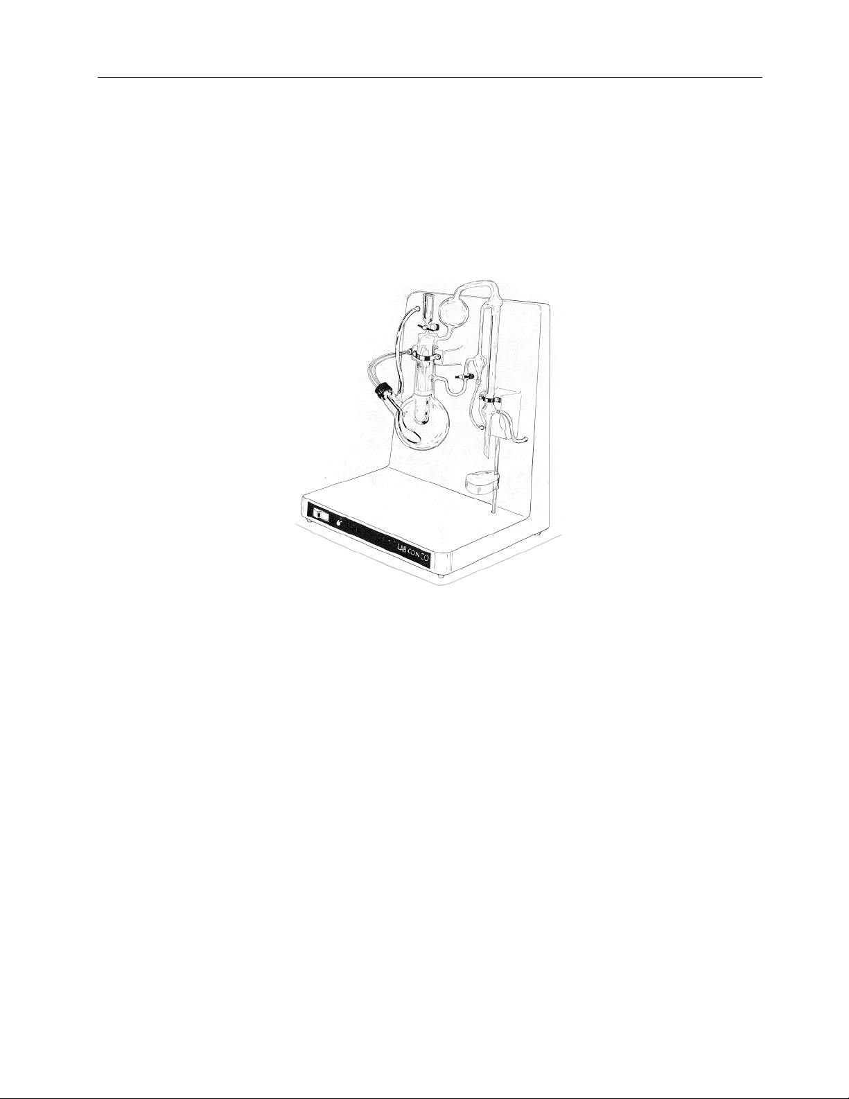
General Description
The Labconco Rapid Distillation Apparatus is designed expressly for rapid, semi-automatic
steam distillation from sulfuric acid digest prepared from nitrogen-bearing materials such as feeds,
grains, soils, plant tissue, water effluent, organic waste food products, etc. Sample digestions are
accomplished utilizing either Labconco’s Micro Distillation Apparatus or Rapid Digestor units.
The distillation apparatus can be used for micro or macro levels of nitrogen determination.
Figure 1
Performance
Your Labconco Rapid Distillation Apparatus has been designed to accept digested samples
up to 4 ml (max.) equivalent of concentrated acid, and is capable of giving reproducible results in
ranges as low as 10 micrograms (gamma) #1% nitrogen. Ideal nitrogen of 0.15 mgs makes this
apparatus an excellent companion for the Labconco Micro and Rapid Digestors
The distillation apparatus many also be utilized for other steam distillations that DO NOT
exceed the volume limitations of the units mixing chamber (approx. 50 to 55 ml).
1
Page 6

INTRODUCTION
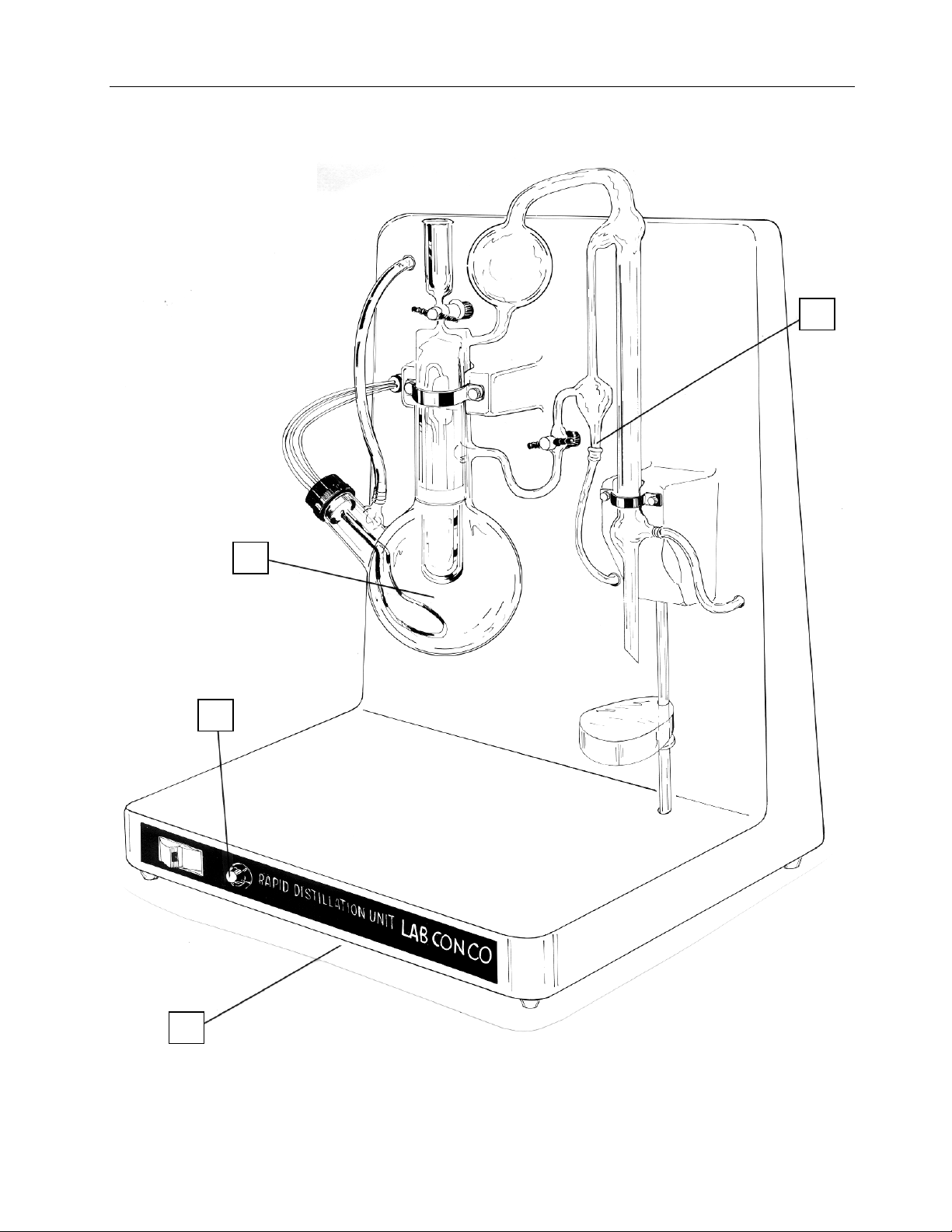
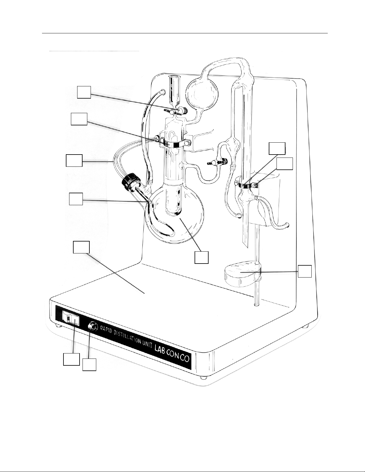
Component Identification
(1) Console. A one piece assembly molded out of linear polyethylene to provide both chemical
resistance and light weight capabilities for the distillation apparatus.
(2) Still. One piece still fabricated from borosilicate glass and featuring chemically inert PTFE
stopcocks. Because the still does not incorporate rubber or plastic tubing connections, the
possibilities of leakage have been greatly reduced.
(3) Variable Heat Control. The electric immersion heater provides fast, efficient heat. Steam
generation starts very rapidly from a cold start. Electrical input to the heater is controlled
by a built-in variable heat control switch, which allows complete control of the steam.
(4) *Flow Control Valve. The unit is supplied with a fine metering valve that is installed
between a water source and the water inlet tube connector to the steam reservoir. Adjust
valve to keep water level in the steam reservoir approximately 2/3 full during distillation.
(5) Aspirator. The unit has a built-in glass aspirator to purge spent samples after
determination. The water used for cooling of this condenser is also used for aspirating. A
twist of the stopcock draws the sample and rinse water down the drain.
*Not shown
2
Page 7
Component Identification
INTRODUCTION
5
3
2
1
Figure 2
3
Page 8
INSTALLATION
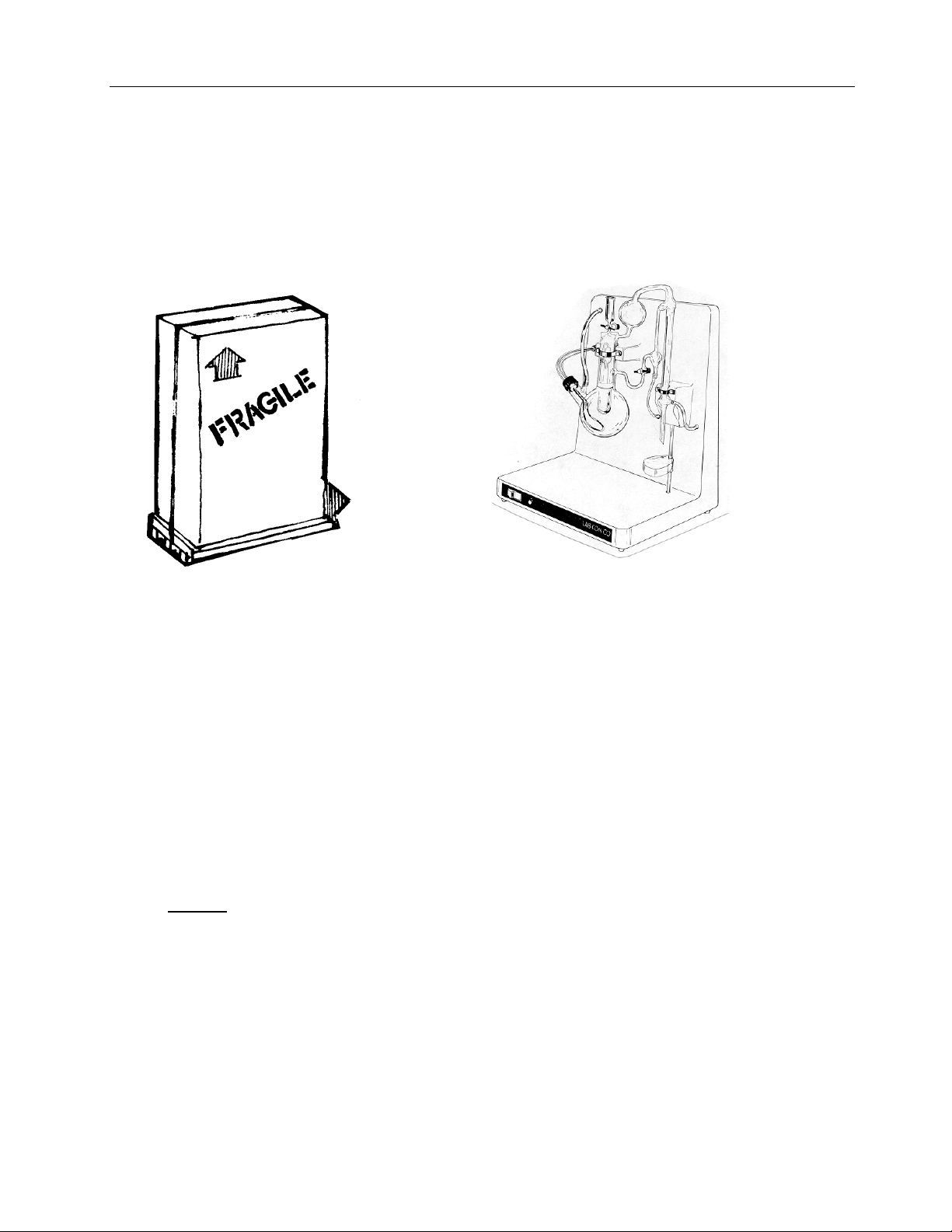
Your Rapid Distillation Apparatus has been shipped to you in one carton. In unpacking,
remove the packing material carefully, checking all material for two separately packed parts. The
carton will contain a heater element assembly and clmaps wrapped in protective paper, and the
one-piece glass still packed between foam pads inside of a cardboard carton.
Inspect this material thoroughly prior to installation and report any damage that may have
occurred in transit.
Figure 3
Installation Factors
Assembly
(1) Remove the condenser clamp screws and clamp from the console.
(2) Lay the console unit on its back and position the glass still assembly on the console, lining
up the glass trap and condenser sections, as shown in Figure 2.
(3) Replace both the large and small clamps, insert and tighten down the clamp screws until
the glassware is firmly attached to the console.
NOTE: Check clearance on the condenser tip with the movable flask support shelf.
Adjust the entire glassware unit, by slightly loosening the clamp screws, so that enough
room is provided to insert the receiver flask. Retighten clamp screws to secure this
position.
(4) Place still in a location having a convenient 115 volt, AC outlet, and accessibility to
distilled water, tap water and drain facilities.
4
Page 9

INSTALLATION
(5) Obtain several lengths of Tygon tubing (5/16" bore x 1/16" wall). Tubing IS NOT
furnished with the unit and may be obtained from local laboratory supply dealers. Tubing
will be used for connecting water lines (refer to steps 6, 11 and 12).
(6) Measure distance from tube connector on steam reservoir through the tubing access port in
console (upper left corner) to a water outlet. Cut tubing and connect to tube connector on
still and water source. If the flow control valve is to be used, install between water source
and tube connector located on top of steam reservoir. The valve is provided with a hose
barb fitting on one end and a female 1/8" NPT connector on the other. Install with ridged
tubing from water source to 1/8" NPT. Connect 5/16" Tygon tubing to the hose barb
fitting. A tee may be installed to allow use of the same water source for the condenser
cooling and steam reservoir..
(7) Remove protective wrapper from formed metal heater element and seal stopper assembly.
NOTE: Water tubing clamps are usually placed on heater “lead wires” to prevent loss in
shipping. Two clamps are provided – remove them from the heater leads and use when
making tubing connections at the tap water inlet and tap water source connection points.
(8) Insert heater assembly in steam reservoir (see labeled diagram in Figure 2).
NOTE: A very tight seal between rubber stopper and neck of the flask must be obtained.
(9) Insert line cord in 115 Volt AC receptacle. Turn off with console “On-Off” switch to
prevent possible heater burn-out.
(10) Connect heater lead wire plug to female receptacle provided on the console.
(11) Connect Tygon tubing to the outlet of the condenser water aspirator. Run tubing through
access port on console to drain area.
(12) Connect Tygon tubing to condenser inlet. Run tubing through access port provided to the
tap water source. Clamp tubing securely at water source and condenser inlet points.
Start-up and Initial Check-out
If all of the assembly steps, as listed previously have been followed, your Rapid Distillation
Apparatus will now be ready for its initial start-up.
The start-up process should begin as follows:
(1) Make sure the illuminated “On-Off” switch is in the off position.
CAUTION: Do not energize heater unit unless heater element is properly immersed in
water.
5
Page 10

INSTALLATION
(2) Fill steam reservoir flask 2/3 full with ammonia free distilled water. Adjust flow control
valve to give approximately 7 ml/minute flow. Proper adjustment of valve will replace the
water lost from the distillation. If the flow control valve is to be used for low level
nitrogen determinations, it may be necessary to install a deionization cartridge (available
from your laboratory supply dealer) between the flow control valve and water source.
Usually a blank determination on reagents and water is sufficient for most low level
nitrogen determinations.
(3) Check sample addition funnel stopcock. Mare sure it is CLOSED!
(4) Close aspirator stopcock located between condenser and steam reservoir.
(5) Turn on tap water source and fill condenser.
(6) Place a small graduated cylinder on receiving holder at output of condenser to measure
distillation rate.
(7) Turn heater control dial to “9.” Press On/Off switch to “On.”
(8) The water in the steam reservoir will begin boiling in about 5-6 minutes. The heater
control setting should be turned down until a distilling rat of 5 ml/min. is obtained. The
flow control valve is adjusted to replace water lost during distillation.
(9) Measure temperature of distillate and adjust cooling water input at tap water source to
maintain distillate temperature of 25°C or lower.
(10) For low level nitrogen determinations, allow steam distillation to continue until distillate is
nitrogen free. Removal of nitrogen entrained in steam reservoir water may require 30
minutes at initial start-up, or if the apparatus has been out of use for sufficient time to allow
nitrogen containing fumes to be reabsorbed in steam reservoir liquid. Add approximately
15 ml of ammonia free distilled water to the mixing chamber through the sample-addition
funnel. Close sample stopcock after test liquid drains through! Open the aspirator
stopcock and siphon off all liquid in the mixing chamber to check out aspirator operation.
Water flow to condenser can be adjusted to increase or decrease “siphon” rate. When
mixing chamber is cleared of the test liquid, close the aspirator stopcock.
(11) The unit is now ready for samples. Refer to the following appropriate method for the
determination of nitrogen content from predigested samples.
6
Page 11

NORMAL OPERATION
Samples Digested Utilizing Micro-Digestor –
Start-up and Operation
The Labconco Rapid Distillation Apparatus is designed to conform with standard Micro
Kjeldahl distillation techniques. The preparation of digested samples, chemical treatment of the
sample prior to distillation and titration techniques following the distillation are adequately
described in A.O.A.C. Methods of Analysis and other technical references, and should be referred
to in ALL cases.
(1) Turn on cooling water and adjust to normal rate.
(2) Turn on heater – check reservoir level and adjust to 2/3 full if required. Set heat control at
“9” on the dial. Allow steam reservoir water to come to “boiling” and turn down heat
control to proper setting. Adjust flow control valve to replace water lost during distillation.
(3) Allow still to reach thermal equilibrium – check for 4-5ml/min. distilling rate, with small
graduate (refer to Step 8 of Start-up and Check Out).
(4) Open aspirator stopcock joining still chamber and water aspirator aspirate inner chamber –
close the stopcock.
(5) Place a receiver flask, containing a volume of receiving solution on shelf at outlet of
condenser.
(6) Check stopcock on sample addition funnel to see that it is closed. Place entire diluted
digest sample in addition funnel.
(7) Open “addition” funnel stopcock to transfer digest sample to the mixing chamber. Close
stopcock.
(8) Rinse digestion flask with several small amounts of ammonia-free distilled water (total
volume of rinses not to exceed 8 to 10 ml). Adding each small rinse to the inner chamber
through the addition funnel separately and closing stopcock after each addition.
(9) Rinse addition funnel with 3 to 4 ml ammonia-free distilled water, leaving some water as a
liquid seal.
(10) Raise receiver flask shelf, positioning it so that the condensate outlet is slightly below the
receiving liquid surface level.
(11) Add strong alkali solution (calculated to produce excess base in mixing chamber when
completely added) to addition funnel. Open funnel SLOWLY and allow alkali to slowly
flow into the mixing chamber. Stop flow if “neutralizing action” becomes too vigorous or
siphon back of receiving solution. Continue intermittent feeding of alkali to mixing
7
Page 12

NORMAL OPERATION
chamber until all of the solution is added. Leave column of caustic in the funnel stem to
act as a liquid seal.
NOTE:
re-calculate required alkali solution strengths so that inner chamber contents will have a
normality of 4 to 8. A small amount of caustic should be left in the addition funnel to act
as a liquid seal during each distillation. If foaming is a problem during distillation, add 1
or 2 drops of anti-foam reagent.
(12) Allow distillation to proceed long enough to complete the quantitative recovery of
ammonia free from the sample. Average time of distilling is 3 to 5 minutes.
(13) Lower receiver flask shelf and allow distillation to continue approximately one minute.
(14) Place receiver flask aside. It is now ready for titration.
(15) Place an extra flask on receiver shelf, open aspirator tube stopcock, to “drain out” the
mixing chamber. Open sample addition stopcock, letting liquid seal pass into the mixing
chamber. Close addition stopcock. Drain out by means of the aspirating action. Follow
with several good washes of ammonia-free distilled water, adding each wash through the
addition funnel, closing the addition stopcock and aspirating the washing solution to the
drain.
NOTE:
(16) The unit is ready to handle the next sample
NOTE: If long delays are encountered between sample runs, aspirate mixing chamber just
prior to sample digest introduction.
Shutdown
(1) Turn off heater with main switch.
(2) Remove receiver flask.
(3) Wash out mixing chamber thoroughly, leaving it about ½ full (10-12 ml – refer to Step 15
of Start-up and Operation).
(4) Turn off cooling water source to condenser and flow control valve.
If reaction is uncontrollable, REDUCE all future acid digest sample volumes and
Close aspirator stopcock before addition of each wash.
8
Page 13

NORMAL OPERATION
Samples Digested Utilizing Rapid Digestor –
Start-up and Operation
Same as information under Samples Digested Utilizing Micro-Digester.
Principle
(1) After sample digestion, utilizing the Labconco Rapid Digestor-4, Rapid Digestor-25, or
equivalent digestion apparatus, a portion of the sample is transferred to the Rapid
Distillation Apparatus. Ammonia is steam distilled into standard acid and back titrated
with standard alkali. Complete recovery of nitrogen is accomplished in 3 – 5 minutes
distillation time.
Apparatus
(1) Labconco Rapid Distillation Apparatus Model 65000. Available from Labconco
Corporation, 8811 Prospect Avenue, Kansas City, MO 64132.
(2) Erlenmeyer Flasks. 125 ml Erlenmeyer flasks for standard acid receiving solution.
(3) Pipets. 20 ml volumetric pipets for sample transfer.
(4) Burets. 15 ml buret for standard acid and standard alkali. Separate burets should be used
for the addition of the acid and alkali.
Reagents
(1) Sodium hydroxide/potassium sulfide. Dissolve 45g solid NaOH in water. While still
warm, dissolve 10g of K2S in the NaOH solution, cool and dilute to 1 liter.
(2) Methyl red indicator. Dissolve 1g methyl red in 200 ml ethyl alcohol.
(3) Sodium hydroxide standard solution. 0.01N, prepare as in AOAC Official Methods of
Analysis, Thirteenth Edition, p. 877.
(4) Sulfuric acid standard solution. 0.05N, prepare as in AOAC Official Methods of Analysis
Thirteenth Edition, p. 877.
Standardize each standard solution with primary standard and check one against the other.
Refer to AOAC Official Methods of Analysis
before use by blank determination with 1g sugar.
, Thirteenth Edition, Chapter 50. Test all reagents
,
9
Page 14

NORMAL OPERATION
Determination
(1) Samples are digested utilizing the Labconco Rapid Digestor 5 place of the 25 place units
equipped with 250 ml volumetric digestion tubes (refer to digestion methods available
upon request from Labconco). After digestion, remove rack of tubes from digestor and
allow to cool for 8 – 10 minutes (cooling time depends upon air flow around tubes). Direct
rapid spray of water (kitchen sink dish rinsing sprayer works well) to bottom of each tube
to dissolve acid digest completely. If precipitate forms, dissolve by manual mixing or by
placing tubes in ultrasonic bath. Low recovery of nitrogen will result if precipitate is not
completely dissolved. Let sample cool, dilute to the mark and mix thoroughly by inversion
20 times. Using a 25 ml buret, prepare the sulfuric acid receiving solution by adding the
calculated amount of 0.05N sulfuric acid standard solution to a 125 ml Erlenmeyer flask.
Add 5 – 7 drops of indicator (see calculating section for amount of standard solution to
add). Dilute volume with water to approximately 70 – 75 ml.
Pipet ml aliquot of sample solution to sample addition funnel on the Rapid Distillation
Apparatus. Distillation rate must be between 4 – 5 ml minute. Adjust water flow control
valve to keep water level in the steam reservoir approximately 2/3 full. Introduce sample
into sample chamber. Rinse funnel with 3 – 4 ml portions of water. Raise 125 ml
Erlenmeyer flask, containing the receiving solution, into position under the condensate
outlet tube of the still. Correct position is where the top of the outlet tube is completely
submerged below the receiving solution liquid level. Add 10 ml + 1 ml of sodium
hydroxide/potassium sulfide to the addition funnel. Slowly add alkali to the sample
chamber. (It is very important to add the caustic slowly, while visually monitoring the
standard acid solution to see that the solution does not siphon back through the condenser
and into the steam reservoir.) Leave column of caustic in the funnel stem to act as a liquid
seal. Distill for 3 – 5 minutes, lower receiving flask and allow distillation to continue for
approximately one minute. Titrate excess standard acid with 0.01N sodium hydroxide
standard solution. Correct for blank determination on reagents.
10
Page 15

CALCULATIONS
11
Page 16

ROUTINE MAINTENANCE
Console
The console is constructed of plastic and resists staining. To preserve its general
appearance, acid and alkali “spills” should be removed as soon as possible by washing and
sponging with a damp cloth.
Glass Still (Replacement)
(1) Disconnect line cord from 115 volt AC outlet disconnect heater plug connections.
(2) Remove heater assembly and stopper.
(3) Disconnect ALL tubing connections on glass still.
(4) Remove clamp screws (4).
(5) Remove clamps (2).
(6) Lift still assembly from console and lay carefully aside.
(7) Remount new glass still assembly and reconnect all parts and tubing, by reversing above
steps.
12
Page 17

ROUTINE MAINTENANCE
Stopcock
The Labconco Rapid Distillation Apparatus is equipped with (2) PTFE stopcocks. The
PTFE stopcocks do not
to wash away any solid particles that might accumulate during long service. If solid particle s
become lodged between the plug and glass barrel, or project from the glass surfaces, they can score
the PTFE plug around its bore and result in a “leaky” plug.
When alkalies or other liquids corrosive to glass are used in PTFE-glass stopcock valve
assemblies, rinse all valve components thoroughly with water after each use. Roughness of the
glass barrel due to liquid concentrate formed on evaporation may score the plug. Additional
information is provided with this unit and may be referred to for service.
require lubricants. The plug and glass barrel may be cleaned with Acetone
Stopcock
Figure 4
13
Page 18
REPLACEMENT PARTS
3
12
13
10
9
14
11
1
8
18
4
Figure 5
14
Page 19

REPLACEMENT PARTS
ITEM
1 65001 Glass micro still assembly with PTFE stopcocks
2 13525 PTFE plug replacements for PTFE stopcock
*3 13237 Heat controller
4 18765 Knob, for heat controller
*5 19175 Fastener, nylon round head, canoe type
*6 13432 Fuse holder
*7 13410 Fuse only – 115 Volt AC AGC-3
8 65008 Receiver flask platform assembly
9 65042 Heater assembly, complete with stopper and male
10 12823 Plugs, heater lead jack, only
11 65021 Housing assembly, complete (less all glassware and
12 65056 Saddle clamp, large
13 65058 Saddle clamp, small
14 19030-08 Screws, for large and small clamps
*15 13174 Transformer (230 V to 115 V, 50/60 Hz, 300 Watt)
*16 19093-26 Nut
*17 65045 Flow control valve
18 13270 Switch-lighted rocker
*Items not shown
PART
NUMBER
DESCRICPTION
plug; 115 VAC, 280 Watts
heater)
15
Page 20
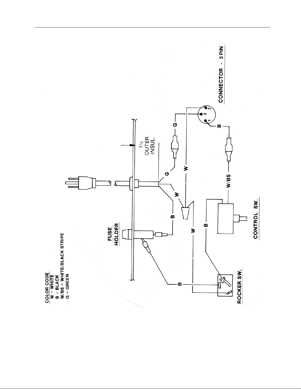
WIRING DIAGRAM
Figure 6
16
Page 21

REFERENCES
Many excellent reference texts and booklets are currently available. The following is a
brief listing:
Official Methods of Analysis of the Association of Official Analytical Chemists
Edition, Washington, District of Columbia, 1980.
Hambleton, L.G. and Noel, R.J., Journal of the Association of Analytical Chemists
1975.
“Digestion Method for the Determination of Protein Nitrogen in Feeds, Foods, Grains, Cereals,
and Grasses Utilizing the Labconco 4-Place Rapid Digestor (R/D-4),” Labconco Extracts 2:880,
Labconco Corporation, Kansas City, MO.
“Digestion Method for the Determination of Protein Nitrogen in Feeds, Foods, Grains, Cereals,
and Grasses Utilizing the Labconco 25-Place Rapid Digestor (R/D-25),” Labconco Extracts 3:880,
Labconco Corporation, Kansas City, MO.
, Thirteenth
, 58:143-145,
17
Page 22

WARRANTY
We are committed to providing our customers with quality equipment and service after the
sale. Part of this objective involves keeping you informed of changes and new product additions.
We therefore request that you take a moment to fill out the product registration card so we may
know your location as well as some of the reasons that prompted you to purchase our products
Labconco Corporation warrants products of its manufacture for one year, from
receipt of the equipment by they purchaser, against defects in materials and workmanship.
This limited warranty covers parts and labor but not transportation and insurance charges.
In the event of a warranty claim, contact the dealer who sold you the product. If the cause is
determined to be a manufacturing fault, the dealer or Labconco Corporation will repair or replace
all defective parts to restore the unit to operation. Under no circumstance shall Labconco
Corporation be liable for indirect, consequential or special damages of any kind. This
statement of warranty may be altered by a specific published amendment. No individual has
authorization to alter the provisions of the warranty policy or its amendments. Lamps and
expendable items such as filters are not covered by this warranty. Damage due to corrosion or
accidental breakage is also not covered.
WARNING: The disposal and/or emission of substances used in connection with this
equipment may be governed by various federal, state or local regulations. All users of this
equipment are urged to become familiar with any regulations that apply in the user’s area
concerning the dumping of waste materials in or upon water, land or air and to comply with such
regulations.
18
Page 23

SHIPPING CLAIMS
If shipment is received in visibly damaged condition, be certain to make a notation on the
delivering carrier’s receipt and have his agent confirm the damage on your receipt. Otherwise, the
damage claim may be refused.
If concealed damage or pilferage is discovered, notify the carrier immediately and retain
the entire shipment intact for inspection. Interstate Commerce Commission rules require that the
claim be filed with the carrier within 15 days after delivery.
NOTE
accepted. Labconco Corporation and its dealers are not responsible for shipping damage. Claims
must be filed directly with the freight carrier by the recipient. If authorization has been received to
return this product, by accepting this approval, the user assumes all responsibility and liability for
biological and chemical decontamination and cleansing. Labconco reserves the right to refuse
delivery of any products, which do not appear to have been properly cleaned and/or
decontaminated prior to return.
: Do not return goods. Goods returned without prior authorization will not be
19
Page 24

CONTACTING LABCONCO
If you have any questions that are not addressed in this manual, or if you need technical
assistance, please contact Labconco’s Customer Service Department at either (800) 821-5525 of
(816) 333-8811, between the hours of 8:00 a.m. and 5:00 p.m., Central Standard Time.
Labconco’s mailing address is:
Labconco Corporation
8811 Prospect Avenue
Kansas City, Missouri 64132-2696
Fax # 816-363-0130
Visit Labconco through the Internet at:
http://www.labconco.com
or
email: labconco@labconco.com
20
 Loading...