

Page 1

RAPID DIGESTORS
Model 23012 Rapid Digestor-25 without digestion tubes
Model 23080 Rapid Digestor - 4 without digestion tubes
INSTRUCTION MANUAL
Product designs are subject to change without notice
© 1998 Labconco Corporation
Form 23058 REV H / ECO A652
Printed in U.S.A
Page 2

TABLE OF CONTENTS
Preface 4
General Description 5
Detailed Operational Function 5
Digestion Unit 5
Control Unit 6
Digestion Tubes, Flask Rack, and Retainer Plate 6
End Plates 7
Fume Removal System (Optional Equipment) 7
Specifications Digestor 25 - Place 8
Specifications Digestor 4 – Place 9
Installation 10
Unpacking 10
Operation & General Kjeldah Digestion Procedure 11
General Digestion for Feed, Grain 11
Routine Maintenance 13
Calibration 13
Troubleshooting 14
Service
Main Power Switch Replacement 15
Strip Heater Replacement 15
Indicator Lamp Replacement 15
Resistor Replacement 16
Ceramic Heater Replacement 16
Sensor Replacement 16
Parts and Service 17
References 18
Replacement Parts 19
Wiring Diagrams 21
Warranty 29
Shipping Claims 30
Contacting Labconco 31
Page 3

PREFACE
Thank you for displaying confidence in us by selecting a Labconco Rapid Digestor. Our
design engineers, assemblers and inspectors have utilized their skills and years of
experience to ensure that the new Labconco Rapid Digestors meets our high standards of
quality and performance.
IMPORTANT NOTICE
This manual should be read carefully by all the end users in order to become familiar
with the operation of the Rapid Digestors. Recommendations are made within the
manual to help you obtain maximum performance and life from your product.
We have included sections on initial set up, operation, maintenance and troubleshooting
to provide you with all the tools necessary to achieve maximum performance.
If you have questions or concerns, do not hesitate to call us at 1-800-821-5525 for
assistance.
WARNING: THE DISPOSAL OF SUBSTANCES USED IN CONNECTION
WITH THIS EQUIPMENT MAY BE GOVERNED BY VARIOUS FEDERAL,
STATE OR LOCAL REGULATIONS. ALL USERS OF THIS EQUIPMENT ARE
URGED TO BECOME FAMILIAR WITH ANY REGULATIONS THAT APPLY
IN THE USERS AREA CONCERNING THE DUMPING OF WASTE
MATERIALS IN OR UPON WATER, LAND OR AIR AND TO COMPLY WITH
SUCH REGULATIONS.
4
Page 4

INTRODUCTION
General Description
The Rapid Digestors are designed for wet digestions on material such as feeds, grains,
soils, plant tissues, water effluent, organic wastes, and food products. These digestions
are made prior to analysis for nitrogen, calcium, phosphorus, heavy metals, micronutrients, and other materials. The system consists of a control unit, a heating unit with
digestion tubes, and a flask rack for transporting tubes. The flask rack is equipped with
removable side panels providing increased heat transfer to the upper part of the digestion
tubes.
The heating unit consists of individual heaters constructed of ceramic materials providing
uniform and efficient heat transfer to the digestion tubes. The heaters are encased with an
efficient insulating material on four sides and the bottom to prevent heat loss, assuring
low energy consumption and safe casing temperatures. The close tolerance fit between
the inner ceramic tube and the digestion solution provides for shorter digestion times and
uniform digestion temperatures of the sample solution. The heating unit is enclosed in a
chemically etched aluminum casing, assuring easily cleaned surfaces with no paint to
flake off and providing a good appearance throughout the unit’s lifetime.
The control unit is of solid state design and regulates the temperature of the individual
heaters uniformly and accurately. The large temperature set point dial assures accurate
and repeatable temperature settings. The unique light display located on the heating unit
assures accurate temperature setting and allows for visual observation of the Digestor’s
operation.
The digestion tubes are thick-walled, rimmed, and made of borosilicate glass. Each tube
is manufactured to close tolerances to assure efficient and uniform digestions. Digestion
tubes are of the straight non-constricted type of approximately 250-ml capacity or with
construction and an accurate volumetric mark placed at 250-ml volume.
Detailed Operational Function
The Labconco Digestor consists of the digestion unit, the control unit, and accessories
(digestion tubes, flask rack, end plates, and retainer plate). The digestor can
simultaneously handle up to 25 samples, each weighing up to 5 g for solid materials or
approximately 25 ml for liquid samples.
Digestion Unit
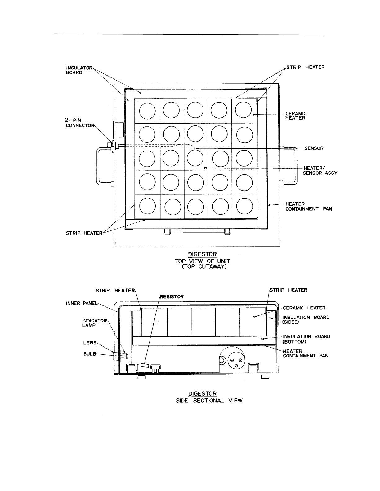
The digestion unit contains electrically heated ceramic cores retained in a pan insulated
from the aluminum casing to reduce heat loss and to prevent the metal casing from
becoming hot. The ceramic cores are precision molded to accommodate the digestion
tubes and provide maximum direct contact with the tubes.
The center heating element with the 25-Place, or the rear left with the 4-Place, contains a
RTD platinum sensor that is encased in ceramic to sense the temperature of the digestor
and signals the control unit providing uniform temperature control.
5
Page 5

INTRODUCTION
CAUTION: The top surface of the digestor is hot during operation and for a period of
time after shutdown. To avoid the possibility of burns, do not touch the surface with bare
hands.
The exposed surfaces of the unit are made of aluminum finished by a chemically etched
process to withstand corrosion. The light(s) located on the front of the digestor indicates
when the digestor has reached set-point temperature and any malfunction that could
occur, along with providing over and under temperature set-point indications. Flashing
of the light(s) indicates proper temperature control.
Control Unit
The solid state proportional controller regulates the temperature of the digestor unit. The
Rapid Digestor-25 control unit is factory set to accept 208/240 volts, 50/60 Hz requiring
20 amp fusing and the 4-Place set to accept 115 volts, 50/60 Hz requiring 15 amp fusing.
Temperatures from a few degrees above ambient to 450° C can be set on the set point
indicator dial. Each controller is factory calibrated for proper temperature setting before
leaving the factory and should not require re-calibration. A calibration resister is
provided for a calibration check of the set-point temperature if required. (Refer to
Maintenance Section of manual for procedure). A red indicator light on the front panel of
the control unit is illuminated when unit is energized. Flashing of the light(s) located on
the digestor unit indicates the set-point temperature, when it has been reached, the
temperature of the digestor is proportionately controlled by the controller.
Digestion Tubes, Flask Rack, and Retainer Plate
Digestor Model 23006 is supplied with one set of thick-walled, heavy rimmed, heat
resistant glass digestion tubes with volumetric calibration marks at 250-ml volume.
Digestor Model 23000 is supplied with tubes having the same features as with Model
23006 except without calibration markings. Models 23012 and 23080 are supplied without digestion tubes. The heavy rims allow the tubes to hang in the stand when the rack is
lifted. The flask rack is constructed of aluminum alloy and holds the tubes during digestion as well as during cooling, dilution, washing, drying, and weighing of samples.
Samples are weighed or volumetrically delivered into the tubes and the digestion mixture
added. The tubes in the rack are then lowered into the digestor unit. The samples are
digested at the proper temperature for a predetermined amount of time. Digestion
temperature and time is determined by the type of sample being digested. After
digestion is complete, the flask rack containing digested samples must be removed from
digestor, cooled and diluted with water. The digestion is now complete and ready for
appropriate determination. The retainer plate (Rapid Digestor 25-Place only) is attached
to the digestor flask rack to lock the tubes in place, allowing the tubes to be emptied,
washed, and dried as a unit, without removal from the rack. The retainer plate is not to
be used during digestion, cooling or dilution of the samples.
6
Page 6

INTRODUCTION
End Plates
The end plates are rectangular aluminum plates that attach to the open ends of the flask
rack during digestion. Closing the open ends of the rack promotes proper refluxing to
wash down the sides of the tubes for complete and efficient digestions. The end plates
are removed during cooling, dilution and washing.
Fume Removal System (Optional equipment)
An optional fume removal system is available to provide removal of the corrosive fumes
expelled during a digestion. The use of this system is highly recommended to prevent
damage to conventional fume removal hoods.
7
Page 7

SPECIFICATIONS
Specifications (Rapid Digestor, 25-Place)
1.
Electrical
Operating Voltage: 208-240V AC single phase
Current (Max.): 16 Amp at 230V AC
Fusing: 25 Amp fuses @208 or 240V AC
operation
Frequency: 50 or 60 Hz
2.
Physical
Weight: Digestion Unit: 78 lbs.
Control Unit: 10.8 lbs.
Tubes: 9.2 lbs./set of 25
Flask Rack: 3.6 lbs.
End Plates: 1.4 lbs.
Size Digestion Unit: 8" H x 19-1/4"W x 19" D
Control Unit: 5-1/8"H x 8" W x 12-1/8"D
Flask Rack: 6-1/2"H x 14-1/4"W x 14-1/4"D
Flask Rack w/ handles 6-1/2"H x 17-3/4"W x 14-1/4"D
End Plate: 6-1/2"H x 14-9/16"W x 1"D
Tubes: Volumetric 11-15/16"L x 1.65 OD
Straight 11-15/16"L x 1.65 OD
Sample Size: Up to 5 grams
3.
Features
Digestion Tubes (Types) 250 ml straight
250 ml constricted with volumetric mark
Capacity
(samples/digestion)
Temperature range Ambient to 450°C
Heat-up time to 410°C Approximately one hour
Temperature readout Set point dial with indication lamps
25
8
Page 8

SPECIFICATIONS
Specifications (Rapid Digestor 4-Place)
1.
Electrical
Operating voltage: 115V AC
Current (Max.): 6 Amp @ 115V AC
Fusing: 8 Amp @ 115V AC
Frequency: 50 or 60 Hz
2.
Physical
Weight (Shipping): 30 Lbs.
Size: Digestion Unit: 6-3/8"H x 9"W x 11-1/4"D
Control Unit 4-3/4"H x 6-3/4"W x 8-1/8"D
Sample size: Up to 5 grams
3.
Features
Digestion tube (types) 250 ml straight
250 ml constricted with volumetric mark
Capacity (samples/digestion) 4
Temperature range Ambient to 450°C
Heat-up time to 410°C Approximately 45 minutes
Temperature readout Set point dial with indication lamps
9
Page 9

INSTALLATION
Unpacking
Use caution when unpacking the digestor and accessories to avoid damage. Remove the
digestor unit from the carton first and carefully inspect all packing material to insure that
no accessories or small parts are discarded by accident. If damage from shipping has
occurred, the customer must file a claim with the carrier IMMEDIATELY! Do not return
any item to Labconco Corporation without written authorization from the factory. Your
local laboratory apparatus dealer can assist you and should be contacted if problems
occur.
Installation
• Locate the digestor unit under a suitable fume removal system to assure complete
removal of fumes and vapors given off during the digestion.
CAUTION: Acid fumes given off during digestion are very corrosive. Digestion
unit must be placed in venting system that is totally resistant to acid fumes or
damage will result to the removal system. It is highly recommended that
Labconco’s fume removal system, designed for acid removal from digestors, be
used in conjunction with a laboratory fume hood.
• Locate control unit outside hood away from any vapors or fumes. Damage to control
unit will result if subjected to corrosive vapors or fumes.
• Connect power cord from control unit to digestor unit. Remove calibration resistor
from 2-pin connector located on rear of control unit. Connect small diameter gray
sensor cord to the 2-prong receptacle provided.
• Connect main power cord from control unit to suitable electrical outlet. (208-240V
AC 3-wire installation fused at 25 amps for the 25-Place digestor or 115V AC for the
4-Place. Refer to electrical specifications pages 5 & 6).
• Adjust temperature set-point dial to approximately 300°C. Turn switch to ON
position. Red pilot light on controller panel will be illuminated along with the red
light(s) on the Digestor’s front panel.
• Allow approximately 40 minutes for unit to reach temperature setting. When unit
reaches temperature, the light(s) on the digestor unit will flash. When light(s) are on,
one half of the time the temperature indicated on the temperature dial has been
reached.
• Place digestion tubes in flask rack. System is now ready for operation.
10
Page 10

NORMAL OPERATION
Operation and General Kjeldah Digestion Procedure for Nitrate Free Samples 1 - 2
General Digestion for feed, grain, etc.
1. Turn main power switch located on front of controller to ON position. Set temper-
ature to 410°C using temperature set point dial on controller. Allow approximately
one hour for unit to reach pre-set temperature (digestor at pre-set temperature when
light(s) located on front of digestor is flashing).
2. Carefully insert the digestion tubes into the holes provided in the flask rack. The
flask rack can be used for convenient handling and transportation of the digestion
tubes.
3. Place weighed, well ground homogenous samples into digestion tubes and add 9g
K2SO4, 0.42 g Hg0, and 15 ml H2SO4.
4. After completing sample and reagent addition to the digestion tubes, carefully elevate
the rack by grasping the handles provided and place in position on the digestor unit.
As the rack is lifted, each tube will rest on its top rim. Carefully lower rack so that
each tube enters its respective hole and bottoms in the base of the unit.
5. If optional fume removal system has been purchased, place system on top of the
digestion tubes. Alignment is accomplished by a side to side, front to back motion.
Adjust water flow to aspirator to the point where all fumes are removed. (Refer to
instruction manual for Fume Removal System).
6. Place end plates on flask rack. These plates completely close the ends of the flask
rack and allow the temperature of the upper portion of the tube to elevate providing
for proper refluxing and condensation of the H2SO4 which washes the carbonized
material back into the digestion solution. (A certain amount of roaming will occur at
the beginning of the digestion. The refluxing of the acid washes any carbonized
material back into the digestion solution. If foaming is uncontrollable, reduce
digestion temperature and/or sample size).
7. Digest sample at 410° for 45 minutes for complete recovery of all types of nitrogen
containing samples. (Digestion time may be less for those samples not containing
refractory nitrogen. Refer to Labconco’s extracts).
Official Methods of Analysis of the Association of Official Analytical Chemists,
Thirteenth Edition, Washington, District of Columbia, 1980.
Methods utilizing copper as the catalyst and 20 minute digestions refer to reference
section of this manual and request appropriate Labconco extracts.
8. After digestion is complete, remove flask rack containing tubes from digestor and
place on heat resistant pad. Avoid having the hot tubes come into contact with a cool
or wet surface. (As a safety precaution, wear asbestos gloves and goggles when
removing the rack and tubes from the digestor).
11
Page 11

NORMAL OPERATION
9. Allow tubes to cool for 5-8 minutes. Dilute digest with approximately 100-ml water
when tubes are cool enough to handle. Dilution must be made before a cake is
formed from precipitated salts, but not before the digest is cool enough to contain the
exothermic reaction. (The cooling period is very important since, in the
determination procedure, caking of the salts will cause low recoveries of the nitrogen
contained in the cake.
10. After dilution of the digested sample, the nitrogen content can be determined by
Labconco’s Rapid Distillation Apparatus, normal Kjeldahl distillation, specific ion
electrode, steam distillation, or by manual or automated colorimetric determinations.
The general method presented for the digestion of total Kjeldahl nitrogen is a basic
method being used in many laboratories doing feeds and grain digestions.
12
Page 12

ROUTINE MAINTENANCE
Periodic cleaning of the surface is necessary to avoid stains from acid spills. This is best
accomplished with a detergent and water solution when the unit is cool. (Disconnect unit
from electrical source).
It is necessary to keep the cores of the ceramic heaters clear of any foreign material to
assure free insertion of the digestion tubes.
Calibration: The controller has been factory calibrated and should not require recalibration. In the event re-calibration is required the following procedure should be
followed:
1. Insert calibration resistor into the 2-pin sensor connector located on the rear of the
control unit.
2. Place ON-OFF switch, located on the controller, to the ON position.
3. Adjust set-point indicator dial to a position where the indicator lights, located on front
panel of digestor, are illuminated 50% of the time.
4. Loosen setscrews on set-point indicator dial and align calibration mark on dial with
pointer label. For calibration of Rapid Digestor 4-Place, align 220°C mark on dial
with pointer label. Retighten setscrews.
5. The digestor is now calibrated to give digestion temperature indicated on set-point
dial.
13
Page 13

TROUBLESHOOTING
Symptom Probable Cause Corrective Measure
Main pilot light does not
illuminate.
Main power fuse blown or
25 Amp fuse on control unit
ON-OFF switch defective Replace switch. Refer to
No heat applied to unit.
Main pilot light
illuminated
ON-OFF switch in off position Turn switch to ON position
Replace fuse or reset circuit
circuit breaker tripped
blown (8 Amp on Rapid
Digestor 4-Place)
Sensor defective Check continuity of sensor
breaker
Check continuity of fuse with
ohmmeter. Replace fuse if
blown. If fuse continues to
blow, locate cause.
Service Section for
replacement procedure.
by placing ohmmeter across
pins 1 & 2 of female sensor
receptacle. If resistance
measurements show sensor to
be open, replace sensor by
following Service Section on
Sensor Replacement.
Indicator lamp not
illuminated.
Defective resistor Check continuity of resistor
Defective ceramic heater Check continuity of each
Uneven heat applied to
unit (not applicable to
Rapid Digestor 4-Place
Bulb defective Check continuity of bulb
with ohmmeter and replace if
defective following Service
Section-Indicator Lamp
Replacement.
for the row of heaters behind
indicator lamp not
illuminated using ohmmeter.
heater contained in the row
behind indicator lamp that is
not illuminated. Replace
defective heater following
Ceramic Heater Replacement
section.
Strip heater defective Check continuity of each
strip heater and replace
defective heater following
Strip Heater Replacement
section.
14
Page 14

SERVICE
Refer to appropriate wiring diagrams or layout drawing for clarification.
Main Power Switch Replacement
• Disconnect main line cord from receptacle.
• Remove the #10-24 machine screws from sides of control unit and remove inner
panel exposing switch.
• Remove wires from old switch and replace switch.
• Rewire new switch referring to wiring diagram located on page 21 of manual. (Refer
to page 25 for Rapid Digestor 4-Place wiring diagram).
• Reassemble control unit.
• Reconnect main power supply.
Strip Heater Replacement (Not applicable to Rapid Digestor 4-Place).
• Disconnect main line cord from receptacle.
• Remove screws from sides of digestor and raise inner panel forward exposing
indicator lamp housings.
• Disconnect spade terminals to indicator lamp freeing the inner panel for complete
removal.
• Remove the six screws from bottom of digestor freeing heater containment pan.
• Tilt heater containment pan to expose wiring.
• Trace wiring to defective heater and disconnect heater wiring.
• Remove heater, replace and rewire.
• Reassemble in reverse order starting with number 3.
• Reconnect main power supply.
Indicator Lamp Replacement
• Disconnect main line cord from receptacle.
• Remove lens cap from defective bulb.
• Remove defective bulb from housing and replace.
• Reinstall lens cap.
15
Page 15
SERVICE
• Reconnect main power supply.
Resistor Replacement
• Follow steps 1-5 under “Strip Heater Replacement”.
• Remove defective resistor from buss bar and terminal strip.
• Install new resistor, retighten screws and reassemble in reverse order.
• Reconnect main power supply.
Ceramic Heater Replacement
• Follow steps 1-5 under “Strip Heater Replacement”.
• Remove defective heater from heater containment pan.
• Install new heater by threading wires through hole in the bottom of the insulator
board. Feed wires through hole and lower heater in place.
CAUTION: Do not bend wires or allow wires to fold up between bottom of heater
casing and insulator board. Heater life will be greatly reduced if heater is not
installed correctly.
• Reconnect heater wires and reassemble in reverse order.
• Reconnect main power supply.
Sensor Replacement
• Follow steps 1-5 under “Strip Heater Replacement”.
• Disconnect sensor leads attached to 2-pin connector located on left side of digestor.
(2-pin connector located on rear of Rapid Digestor 4-Place).
• Remove heater containing the sensor. (Refer to layout sketch on page 23 for 25Place or to page 27 for 4-Place). Heater-sensor assembly containing defective sensor
may be used as heater only by breaking sensor flush with bottom of heater.
• Install new heater sensor assembly by carefully threading wires through holes in the
bottom of the insulator board. Feed wires through holes and lower heater in place.
16
Page 16

SERVICE
CAUTION: Do not bend wires or allow wires to fold up between bottom of heater
casing and insulator board. Heater and sensor life will be greatly reduced if heater is
not installed correctly.
• Reconnect heater wires and solder sensor wires to the 2-pin connector.
• Reconnect main power supply.
• Recalibrate unit by following calibration procedure in Maintenance Section of this
manual.
Parts and Service
• If a problem should arise, please contact your local laboratory apparatus dealer
through whom you purchased the Labconco products. Please include Labconco
catalog and serial numbers on all phones or letter inquiries to obtain prompt action
on your particular unit. Consult nameplates to obtain this information. If contacting
Labconco directly, please furnish the name of the dealer from whom you purchased
the equipment.
WARNING: PERCHLORIC ACID IS A VERY RAPID OXIDIZER. IT
COMES TO A BOIL AT RELATIVELY LOW TEMPERATURES, WITH THE
LIQUID CONTENTS TOTALLY EVAPORATED IN A SHORT AMOUNT OF
TIME. THE RESIDUE WHICH REMAINS AFTER THE LIQUID IS DRAWN
OFF BECOMES ANHYDROUS AND VERY UNSTABLE.
FOR THIS REASON, LABCONCO WARNS AGAINST THE USE OF
PECHLORIC ACID WITH THIS EQUIPMENT AS A REACTION COULD
RESULT.
17
Page 17

REFERENCES
Official Methods of Analysis of the Association of Official Analytical Chemists,
Thirteenth Edition, Washington, D.C., 1980.
Hambleton, L.G. and Noel, R. J., Journal of the Association of Analytical Chemists, 58;
143-145, 1975.
Noel, R.J. , and Hambleton, L.G., Journal of the Association of Analytical Chemists, 59:
134-140, 1976.
Semi-Automated Method for Total Protein Nitrogen in Feeds - Applications Wall, L.L.,
Sr., Gehrke, C.W., and Smith, R.A., University of Missouri, Columbia, Experiment Station Chemical Laboratories, Columbia, Missouri.
“The Determination of Nitrogen Content from Predigested Samples with the Labconco
Rapid Distillation Apparatus”, Labconco Extracts 1:780, Labconco Corporation, Kansas
City, Missouri.
“Digestion Method for the Determination of Protein Nitrogen in Feeds, Grains, Cereals,
and Grasses Utilizing the Labconco 4-Place Rapid Digestor”, Labconco Extracts 2:880,
Labconco Corporation, Kansas City, Missouri.
“Digestion Method for the Determination of Protein Nitrogen in Feeds, Foods, Grains,
Cereals, and Grasses Utilizing the Labconco 25-Place Rapid Digestor”, Labconco
Extracts 3:880, Labconco Corporation, Kansas City, Missouri.
18
Page 18

REPLACEMENT PARTS
Rapid Digestor 25-Place
DIGESTOR - *1
Catalog No. Description
12761 Lens Cap, Red
12762 Indicator Lamp
23034 Heater Assembly with sensor cemented in place
13249 Resistor, 2 ohm 20 W
13459 Strip, Heater
23020 Assembly, Heater
23030-25 Tube Digestion, 250 ml volumetric (Pkg. of 25)
23040-25 Tube, Digestion with NO volumetric marking. (Pkg. of 25)
23051 Flask Rack
CONTROLLER - *2
Catalog No. Description
12707 Pilot Light, 230V
13240 Switch, DPST
23119 Control Assembly
23032 Calibration Resistor
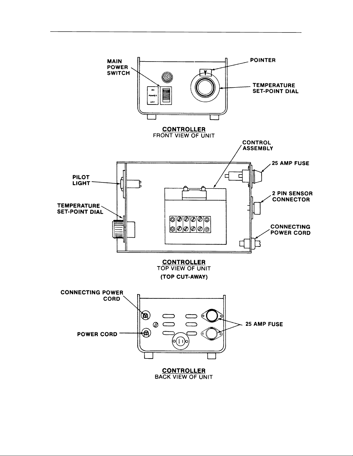
*1. Refer to page 24 for digestor parts identification.
*2. Refer to page 23 for controller parts identification.
19
Page 19

REPLACEMENT PARTS
Rapid Digestor 4-Place
DIGESTOR - *1
Catalog No. Description
12767 Lens Cap, Red
12766 Indicator Lamp
13249 Resistor, 2 ohm 20 W
23084 Assembly, Heater
23030-05 Tube Digestion, 250 ml volumetric (Pkg. of 5)
23040-05 Tube, Digestion with NO volumetric marking. (Pkg. of 5)
23097 Flask Rack
CONTROLLER - *2
Catalog No. Description
12769 Pilot Light, 120V
13257 Switch, DPST
23124 Control Assembly
23032 Calibration Resistor
*1. Refer to page 28 for digestor parts identification.
*2. Refer to page 27 for controller parts identification.
20
Page 20

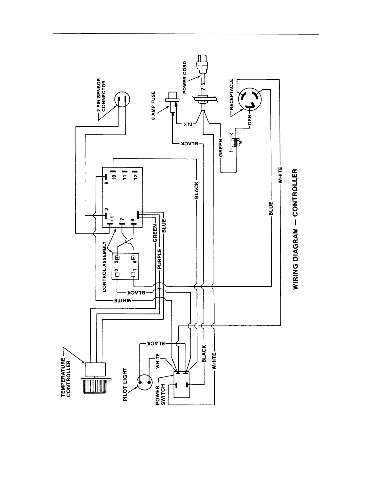
Wiring Diagram - Controller
WIRING DIAGRAM
21
Page 21

WIRING DIAGRAM
Wiring Diagram - Digestor
22
Page 22
WIRING DIAGRAM
23
Page 23
WIRING DIAGRAM
24
Page 24
WIRING DIAGRAM
25
Page 25

WIRING DIAGRAM
26
Page 26

WIRING DIAGRAM
27
Page 27

WIRING DIAGRAM
28
Page 28

WARRANTY
Labconco provides a warranty on all parts and factory workmanship. The warranty
includes areas of defective material and workmanship, provided such defect results from
normal and proper use of the equipment.
The warranty for all Labconco products will expire one year from date of installation or
two years from date of shipment from Labconco, whichever is sooner, except the
following:
• Purifier® Delta® Series Biological Safety Cabinets carry a three-year warranty
from date of installation or four years from date of shipment from Labconco,
whichever is sooner.
• Carts carry a lifetime warranty.
• Glassware is not warranted from breakage when dropped or mishandled.
This limited warranty covers parts and labor, but not transportation and insurance
charges. In the event of a warranty claim, contact Labconco Corporation or the dealer
who sold you the product. If the cause is determined to be a manufacturing fault, the
dealer or Labconco Corporation will repair or replace all defective parts to restore the
unit to operation. Under no circumstances shall Labconco Corporation be liable for
indirect, consequential, or special damages of any kind. This statement may be altered by
a specific published amendment. No individual has authorization to alter the provisions
of this warranty policy or its amendments. Lamps and filters are not covered by this
warranty. Damage due to corrosion or accidental breakage is also not covered.
29
Page 29

SHIPPING CLAIMS
If a shipment is received in visibly damaged condition, be certain to make a notation on
the delivering carrier’s receipt and have their agent confirm the damage on your receipt.
Otherwise, the damage claim may be refused.
If concealed damage or pilferage is discovered, notify the carrier immediately and retain
the entire shipment intact for inspection. Interstate Commerce Commission rules require
that the claim be filed with the carrier within 15 days after delivery.
NOTE: Do not return goods. Goods returned without prior authorization will not be
accepted. Labconco Corporation and its dealers are not responsible for shipping damage.
Claims must be filed directly with the freight carrier by the recipient. If authorization has
been received to return this product, by accepting this approval, the user assumes all
responsibility and liability for biological and chemical decontamination and cleansing.
Labconco reserves the right to refuse delivery of any products, which do not appear to
have been properly cleaned and/or decontaminated prior to return.
30
Page 30

CONTACTING LABCONCO
If you have any questions that are not addressed in this manual, or if you need technical assistance,
please contact Labconco’s Sales Information at 800-821-5525 and Service Information at 800-5227658, or 816-333-8811 between the hours of 7:00 a.m. and 6:00 p.m. Central Standard Time.
Labconco’s mailing address is:
Labconco Corporation
8811 Prospect Avenue
Kansas City, Missouri 64132
Visit Labconco through the Internet at:
http://www.labconco.com
or
email:labconco@labconco.com
31
 Loading...