

Labconco Purifier Axiom 30441 Series, Purifier Axiom 30461 Series, Purifier Axiom 30468 Series, Purifier Axiom 30448 Series User Manual
Labconco Corporation
8811 Prospect Avenue
Kansas City, MO 64132-2696
800-821-5525, 816-333-8811
FAX 816-363-0130
E-MAIL labconco@labconco.com
HOME PAGE www.labconco.com
To receive important product updates,
complete your product registration card
online at register.labconco.com
User’s Manual
Purifier
®
Biological Safety Cabinets
Models
30441 Series 30448 Series
30461 Series 30468 Series
Please read the User’s Manual before operating the equipment.
TYPE
C1
Original instructions

Original instructions
This page is intentionally blank.
Original instructions
Warranty
Labconco Corporation provides a warranty to the original buyer for the repair or replacement of parts and
reasonable labor as a result of normal and proper use of the equipment with compatible chemicals. Broken
glassware and maintenance items, such as filters, gaskets, light bulbs, finishes and lubrication are not
warranted. Excluded from warranty are products with improper installation, erratic electrical or utility supply,
unauthorized repair and products used with incompatible chemicals.
Purifier® Axiom® Biological Safety Cabinets carry a five-year warranty from date of installation or six years
from date of shipment from Labconco, whichever is sooner. Warranty is non-transferable and only applies to
the owner (organization) of record.
Buyer is exclusively responsible for the set-up, installation, verification, decontamination or calibration of
equipment. This limited warranty covers parts and labor, but not transportation and insurance charges. If the
failure is determined to be covered under this warranty, the dealer or Labconco Corporation will authorize
repair or replacement of all defective parts to restore the unit to operation. Repairs may be completed by 3rd
party service agents approved by Labconco Corporation. Labconco Corporation reserves the rights to limit this
warranty based on a service agent’s travel, working hours, the site’s entry restrictions and unobstructed access
to serviceable components of the product.
Under no circumstances shall Labconco Corporation be liable for indirect, consequential, or special damages
of any kind. This warranty is exclusive and in lieu of all other warranties whether oral, or implied.
Copyright © 2016 Labconco Corporation. The information contained in this manual and the accompanying
products are copyrighted and all rights reserved by Labconco Corporation. Labconco Corporation reserves
the right to make periodic design changes without obligation to notify any person or entity of such change.
Returned or Damaged Goods
Do not return goods without the prior authorization from Labconco. Unauthorized returns will not be
accepted. If your shipment was damaged in transit, you must file a claim directly with the freight carrier.
Labconco Corporation and its dealers are not responsible for shipping damages.
The United States Interstate Commerce Commission rules require that claims be filed with the delivery
carrier within fifteen (15) days of delivery.
Limitation of Liability
The disposal and/or emission of substances used in connection with this equipment may be governed by
various federal, state, or local regulations. All users of this equipment are required to become familiar with
any regulations that apply in the user’s area concerning the dumping of waste materials in or upon water,
land, or air and to comply with such regulations. Labconco Corporation is held harmless with respect to
user’s compliance with such regulations.
Contacting Labconco Corporation
If you have questions that are not addressed in this manual, or if you need technical assistance, contact
Labconco’s Customer Service Department or Labconco’s Product Service Department at 1-800-821-5525
or 1-816-333-8811, between the hours of 7:30 a.m. and 5:30 p.m., Central Standard Time.
Part #3848320 Rev. E
ECO K541

Original instructions
TABLE OF CONTENTS
CHAPTER 1: INTRODUCTION 1
CHAPTER 2: PREREQUISITES 2
Space Requirements 2
Clearance 2
Location Requirements 3
Exhaust Requirements 4
Electrical Requirements 6
Service Line Requirements 7
CHAPTER 3: GETTING STARTED 8
Unpacking the Biosafety Cabinet 9
Moving and Lifting the Biosafety Cabinet 9
Installing the Biosafety Cabinet on an Existing Work Surface 10
Installing the Biosafety Cabinet on a Labconco Base Stand 10
Telescoping Base Stands 10
Manual or Electric Hydraulic Lift Base Stands 10
SoLo™ Electric Hydraulic Lift Base Stands 11
Preparing the Biosafety Cabinet for Operation 11
Connecting the Biosafety Cabinet to Utility Service Lines 12
Optional Exhaust Connection Requirements 13
Exhaust Connection Configuration 14
Connecting the Axiom to an Exhaust System 14
Selecting the Configuration Menu 15
Disconnecting the Axiom from an Exhaust System 18
Selecting the Configuration Menu 19
Optional Vacu-PassTM Cord and Cable Portal Use 21
Drain Valve Installation 22
Initial Certification 23
CHAPTER 4: PERFORMANCE FEATURES AND SAFETY
PRECAUTIONS 24
HEPA Filters 25
ULPA Filters 25
Laminar Airflow 26
Directional Airflow 27
ChemZone™ Directly Exhausted Work Zone 28
Motor/Blowers 29

Original instructions
Cabinet Air Intakes (Grilles) 30
Ultraviolet (UV) Lamp 30
Safety Precautions 31
CHAPTER 5: USING THE CABINET 33
System Reset Switch 33
Blower Startup Sequence 33
Information Center 34
Alarm Screens 35
Operating the Sliding Sash 36
Starting the Biosafety Cabinet 36
The Axiom Touchpad 37
Navigating the Axiom Menu Screens 38
Navigating the MyLogicTM Menu Screens 39
Setting the Clock 39
Configuring the Axiom 40
Navigating the Settings Menu Screens 41
Display Options 41
Units of Measure 41
Startup Tone 42
Security Lock 42
RS-232 Output Rate 42
UV Settings 43
UV Lamp Hourmeter 43
Reset UV Lamp Hourmeter 43
Change UV Lamp Life 44
Service Menu Screens 44
Timer Operation 44
Interval Timer Operation 44
Stopwatch Timer Operation 45
If An Airflow Alert Activates 45
Resetting the Airflow Alert System 45
Working in the Biosafety Cabinet 45
CHAPTER 6: MAINTAINING THE CABINET 49
Routine Maintenance Schedule 49
Service Operations 50
Center Work Surface Removal 50
Wing Work Surfaces Removal 51
Front Grille Removal 52
Front Panel Removal & Installation 53
Changing the Fluorescent Lamps 54
Changing the Optional UV Lamp 54
Resetting a Circuit Breaker 54
Storage 55

Original instructions
CHAPTER 7: TROUBLESHOOTING 56
APPENDIX A: COMPONENTS 59
APPENDIX B: DIMENSIONS 61
APPENDIX C: SPECIFICATIONS 63
Electrical Data 63
Motor Specifications 63
Environmental Conditions 63
APPENDIX D: ACCESSORIES 64
APPENDIX E: QUICK CHART 65
CAUTION – See Manual. When this symbol is on the unit it
indicates a caution that is detailed in this manual.
ATTENTION - Voir manuel. Lorsque ce symbole est allumé
l'appareil, il indique une mise en garde qui est indiqué dans
ce manuel.
1
Original instructions
Chapter 1:
Introduction
Congratulations on the purchase of a Labconco® Purifier Axiom® Biosafety
Cabinet. The biosafety cabinet is designed to protect you, the product and the
laboratory environment from biohazardous aerosols. The Axiom is the result
of years of experience in manufacturing biohazard cabinetry, and users like
you suggested many of its features.
This biosafety cabinet offers many unique features to enhance safety,
performance and ergonomics. To take full advantage of them, please acquaint
yourself with this manual and keep it handy for future reference. If you are
unfamiliar with how biosafety cabinets operate, please review Chapter 4:
Performance Features and Safety Precautions before you begin working in
the cabinet. Even if you are an experienced biosafety cabinet user, please
review Chapter 5: Using the Cabinet; it describes the biosafety cabinet’s
features so that you can use it efficiently.
This manual and other technical information is available in PDF format
at our website: www.labconco.com.
If the unit is not operated as specified in this manual it may impair the
protection provided by the unit.
Si l'unité n'est pas utilisée comme spécifié dans ce manuel il peut
diminuer la protection fournie par l'unité.
Product Service 1-800-522-7658

2
Original instructions
Chapter 2:
Prerequisites
Before you install the Axiom, you need to prepare the site for installation.
Examine the location where you intend to install the cabinet. You must be
certain that the area is level and of solid construction. In addition, a dedicated
source of electrical power must be located near the installation site.
Carefully read this chapter to learn:
Location requirements.
Electrical power requirements.
Exhaust requirements.
Service utility requirements.
Space requirements.
Refer to Appendix C: Specifications, for complete biosafety cabinet electrical
and environmental conditions, specifications and requirements.
Space Requirements
The overall dimensions for the 4-foot Axiom are 64.2 inches (163 cm) high, 32.2
inches (82 cm) deep, and 54.2 inches (138 cm) wide. The overall dimensions for
the 6-foot Axiom are 64.2 inches (163 cm) high, 32.7 inches (83 cm) deep, and
78.2 inches (199 cm) wide.
Complete dimensions for the Axiom C1 biosafety cabinets are shown in
Appendix B: Dimensions.
Clearance
A minimum clearance of at least 4 inches (100 mm) is suggested on the top
and 6 inches (150mm) on both sides of the cabinet for service.
Product Service 1-800-522-7658
Chapter 2: Prerequisites
3
Original instructions
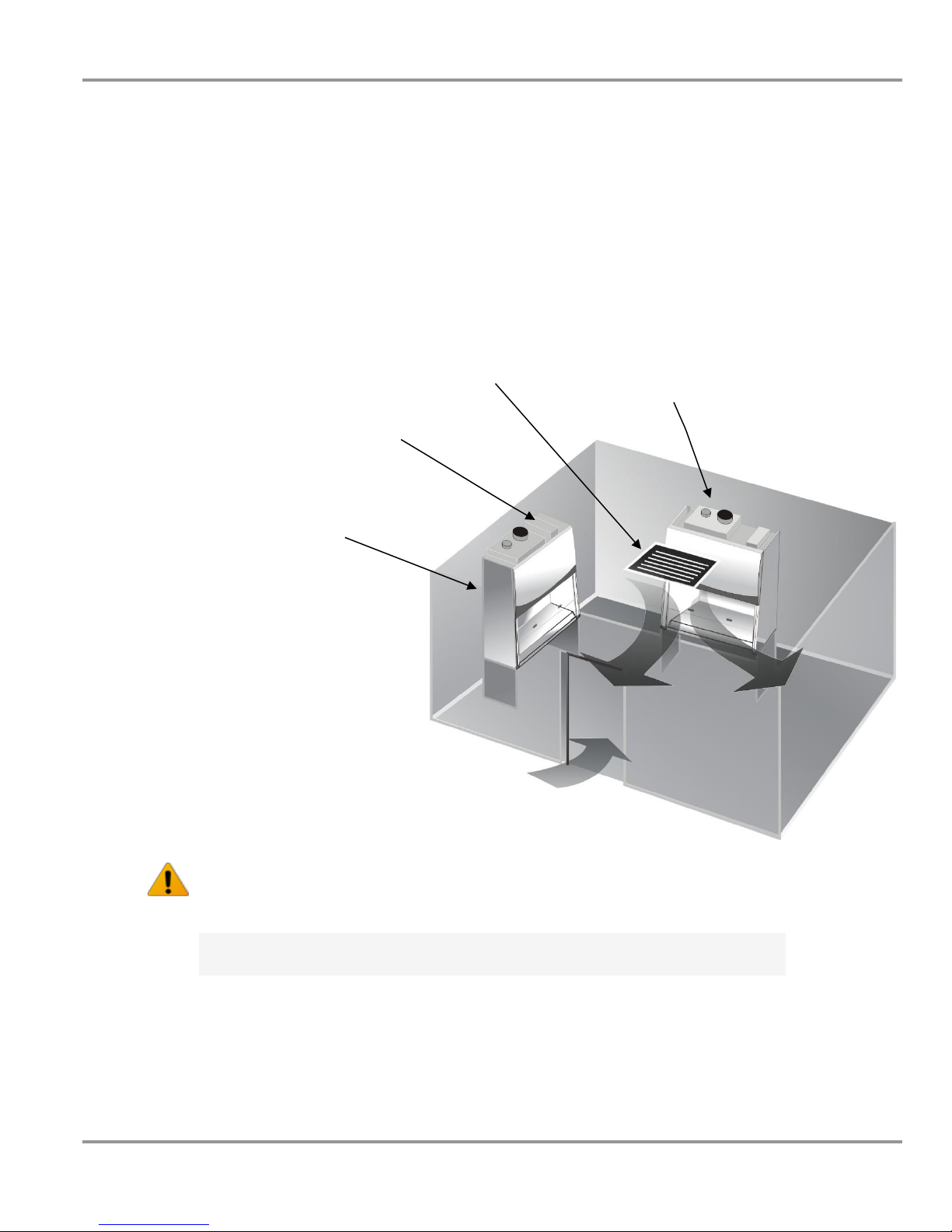
Figure 2-1a
Location Requirements
Note: The biosafety cabinet should be located away from traffic patterns,
doors, fans, ventilation registers, fume hoods and any other air-handling
devices that could disrupt its airflow patterns. All windows in the room
should remain closed. Figure 2-1a shows the preferred location for the
biosafety cabinet.
Air register blocked or redirected
to prevent cabinet disruption
Alternate location
Main Disconnect Device
(Power cord plug in back
of the electronics module).
Preferred location
Do not position the unit so that it is difficult to operate the main
disconnect device.
Ne placez pas l'appareil de sorte qu'il est difficile de faire fonctionner le
dispositif principal de déconnexion.
Product Service 1-800-522-7658
Chapter 2: Prerequisites
4
Original instructions
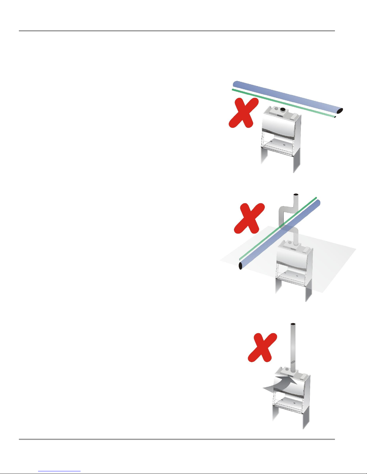
Figure 2-1b
Figure 2-1c
Figure 2-1d
If you intend to connect the biosafety cabinet to
an exhaust system:
NOTE: Only connect the cabinet to a suitable exhaust
system, one dedicated to the cabinet itself, or
dedicated to exhausting laboratory ventilation
equipment. DO NOT connect the unit to the building’s
HVAC system room exhaust.
Examine the location to ensure that it accommodates
the cabinet’s exhaust duct. The area directly above the
cabinet’s exhaust port should be clear of structural
elements, water and utility lines, or other fixed
obstructions. There should be enough clearance to
accommodate a 10-inch diameter duct.
Avoid cabinet locations that require an elbow
directly above the cabinet’s exhaust connection or
an excessive number of elbows in the exhaust
system. There should be a straight length 10 duct
diameters long between the cabinet and any elbow,
and between subsequent elbows.
The Inlet Relief Valve located on the top of the cabinet is
designed to draw a maximum of 100 CFM (2.83 m3/m).
Attempting to draw additional room air through the valve
(room air exhaust), can result in unstable cabinet operation.
Product Service 1-800-522-7658
Chapter 2: Prerequisites
5
Original instructions
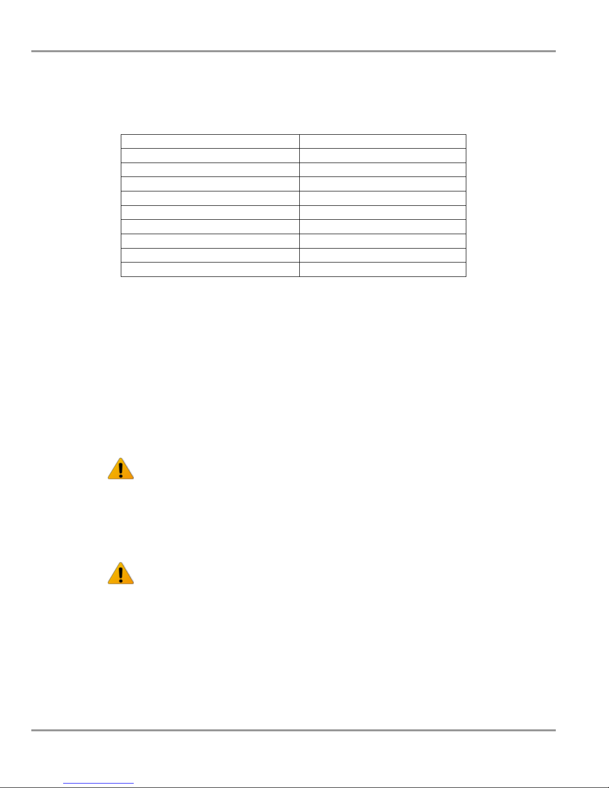
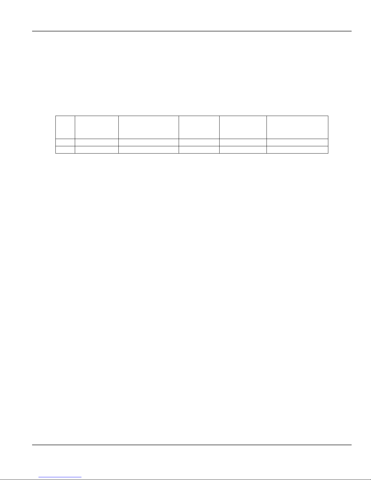
Axiom Type C1
Airflows
Airflow Volume
Concurrent
Balance Value
Recommended
Duct Vacuum1
ft3/min
m3/sec
ft3/min
m3/sec
WC
Pa
4-foot, 8" Sash
323
0.15
387
0.18
0.30
75
4-foot, 10" Sash
400
0.19
480
0.23
0.30
75
6-foot, 8" Sash
463
0.22
556
0.26
0.30
75
6-foot, 10" Sash
570
0.27
684
0.32
0.30
75
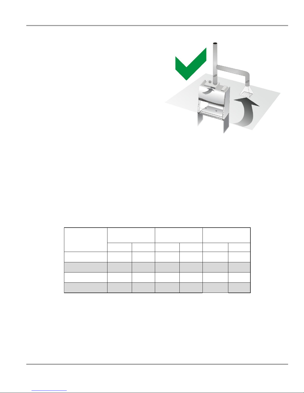
Figure 2-1e
Table 2-1
If additional room exhaust is needed
to be drawn through the exhaust
system, install an additional duct and
balancing damper downstream of the
cabinet’s damper. This will allow for
proper balancing of the system.
The exhaust system must be capable of moving the following volumes of
exhaust air at the negative pressures listed. The Airflow Volumes are the
values recorded via a direct measurement using a flow hood at the cabinet.
The Concurrent Balance Values are measured in the exhaust duct via
traverse methodology, and will always be higher due to differences in volume
measurement methodologies.
1 – Unlike Type B cabinets, the recommended vacuum will remain constant
throughout the life of the Exhaust HEPA filter. Duct vacuums below 0.2 WC
(25 Pa), or above 0.5 WC (125 PA) may result in erratic operation.
Product Service 1-800-522-7658
Chapter 2: Prerequisites
6
Original instructions
Model #
Requirements
30441xx0x, 30448xx0x
115 VAC, 60 Hz, 16 Amps
30441xx1x, 30448xx1x
100 VAC, 50/60 Hz, 16 Amps
30441xx-20, 30, 40, 50, 60, 70
230 VAC, 50/60 Hz, 8 Amps
30448xx-20, 30, 40, 50, 60, 70
230 VAC, 50/60 Hz, 8 Amps
30461xx0x, 30468xx0x
115 VAC, 60 Hz, 16 Amps
30461xx1x, 30468xx1x
100 VAC, 50/60 Hz, 16 Amps
30461xx-20, 30, 40, 50, 60, 70
230 VAC, 50/60 Hz, 8 Amps
30468xx-20, 30, 40, 50, 60, 70
230 VAC, 50/60 Hz, 8 Amps
Table 2-1
Electrical Requirements
The biosafety cabinet models have the following electrical requirements:
Note: A dedicated outlet with an appropriate circuit breaker should be
located as close as possible to the right rear side of the cabinet, at a
height even with, or higher than, the top of the bench or stand. Models
rated for 100 or 115 VAC will require a 20 Amp outlet. Consult your
local electrical codes for properly rated circuit breakers. For safe
operation the dedicated outlet must provide the protective earthing
ground connection to the cabinet.
Note: On 100 and 115 VAC models, both electrical outlets are protected by a
ground fault interrupter circuit (GFIC). Labconco does not recommend
plugging the biosafety cabinet into a GFIC outlet.
Electrical outlets in the cabinet are restricted to 5 amps
maximum current.
Prises électriques dans l'armoire sont limitées à 5 courant
maximum ampères.
Do not use any detachable power cord that is not adequately
rated for the unit.
Ne pas utliser un fil électrique amovible qui n’est pas du tension
nominale de l’appareil.
Product Service 1-800-522-7658

Chapter 2: Prerequisites
7
Original instructions
Service Line Requirements
All utility service lines should be ¼ inch O.D., brass, copper, or stainless
steel, and equipped with an easily accessible shut-off valve. The service
valves are rated for operation at 40 PSI (275 kPa). If the service line pressure
exceeds this, it must be equipped with a pressure regulator to reduce the line
pressure.
Note: The use of flammable gases or solvents should be avoided in the
biosafety cabinet. Open flame in the cabinet will disrupt the laminar airflow
in the cabinet and may damage the HEPA filters. Flammable gases or
solvents may reach explosive concentrations in the cabinet or ductwork. If
you feel that the procedure requires the use of an open flame or flammable
materials, contact the institution’s safety office.
The use of air or gases under high pressure should be avoided as they may
seriously disrupt the airflow patterns in the cabinet.
Product Service 1-800-522-7658

8
Original instructions
Chapter 3:
Getting Started
Now that the installation is properly prepared, you are ready to inspect,
install, and certify the Axiom biosafety cabinet. This chapter covers how to:
Unpack and move the biosafety cabinet.
Install the cabinet.
Connect the electrical supply source.
Connect the service lines.
Connect to an exhaust system (optional).
Arrange certification of the biosafety cabinet.
Tools required for installation the biosafety cabinet include two 1/2"
wrenches, a flat-blade screwdriver, a #2 Phillips screwdriver, and a
carpenter’s level.
Note: The biosafety cabinet models weigh between 630–900 lbs. (286-408
kg). The shipping pallet allows for lifting with a mechanical lift truck or
floor jack.
Product Service 1-800-522-7658
Chapter 3: Getting Started
9
Original instructions
Unpacking the Biosafety Cabinet
Carefully remove the outer carton and inspect the cabinet for damage that
may have occurred in transit. If the biosafety cabinet is damaged, notify the
delivery carrier immediately and retain the entire shipment intact for
inspection by the carrier.
Note: United States Interstate Commerce Commission rules require that
claims be filed with the delivery carrier within fifteen (15) days of delivery.
Do not return goods without the prior authorization of Labconco.
Unauthorized returns will not be accepted.
If the cabinet was damaged in transit, you must file a claim directly with the
freight carrier. Labconco Corporation and its dealers are not responsible for
shipping damages.
Do not discard the carton or packing material for the biosafety cabinet until
all of the components have been checked, installed and tested.
The cabinet is secured to the pallet in two places on each side. To access the
nuts and bolts, remove the side panels by removing and keeping the two
Phillips screws on both panels. Swing the front of each panel away from the
cabinet, and lift it straight up to remove the panel from the cabinet.
Note: The side panels must be removed to access the fasteners that secure the
biosafety cabinet to the pallet. DO NOT ATTEMPT TO LIFT THE
BIOSAFETY CABINET BY THE SIDE PANELS; DAMAGE WILL
OCCUR.
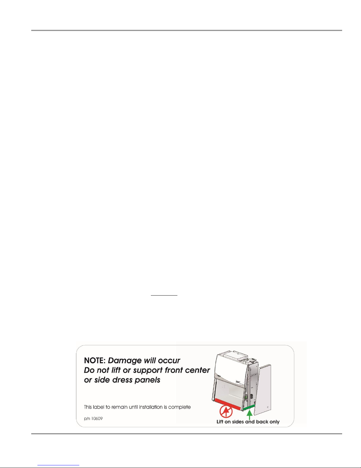
Moving and Lifting the Cabinet
Move the cabinet, attached to its pallet, by using a floor jack, or a furniture
dolly underneath the unit. DO NOT move the cabinet by tilting it onto a hand
truck. When lifting the cabinet DO NOT lift the cabinet in the middle front
area of the hull. Lifting here may bend or distort the bottom of the cabinet,
causing damage to the unit.
Product Service 1-800-522-7658

Chapter 3: Getting Started
10
Original instructions
Width
Base Stand w/Feet Model #
4'
3401004
6'
3401006
Width
Manual Lift Stand #
Electric (115V) Lift Stand #
Electric (230V) Lift Stand #
4'
3780201
3780101
3780104
6'
3780202
3780102
3780105
Table 3-1
Table 3-2
Installing the Biosafety Cabinet on an Existing
Work Surface
Note: The biosafety cabinet is very top heavy. Use caution when lifting or
moving it.
When installing the biosafety cabinet onto an existing work surface or benchtop,
ensure that the structure can safely support the combined weight of the cabinet
and any related equipment. The work surface should be at least as wide as the
cabinet and 31 inches (787 mm) deep to properly support the unit. A hole or
notch may be cut in the supporting surface in the right front corner to
accommodate the optional drain valve.
Installing the Cabinet on a Labconco Base Stand
Labconco offers accessory Base Stands in a variety of configurations to suit
your particular needs. Stands can be ordered with adjustable telescoping legs
or with a manually or electrically adjustable hydraulic lift.
Telescoping Base Stands
These stands are included with some Axiom models, or are available
separately. The base stands for each width cabinet are listed in Table 3-1
below. An optional caster wheel kit is available (part # 3730500).
Manual or Electric Hydraulic Lift Base Stands
These base stands offer infinitely adjustable height between 25.5 and 33.5
inches (648 to 851 mm), giving a cabinet work surface height of 28.0 to 36.0
inches. The height is adjusted either by a manual (hand crank) or electric
pump that drives the hydraulic legs of the stands. All of the hydraulic stands
are equipped with fixed feet, but can be converted to caster wheels with the
addition of Caster Kit #3784000. The base stands for each cabinet size is
listed in Table 3-2 below.
Note: When installing the cabinet on the hydraulic lift base stand, ensure that
the hydraulic lines and the electrical cord are clear of any obstructions before
installing the cabinet on the stand or operating the lift system.
Product Service 1-800-522-7658
Chapter 3: Getting Started
11
Original instructions
115V SoLo
Stand
230V SoLo
No. America Plug
230V SoLo
UK Plug
230V SoLo
Schuko Plug
230V SoLo China/
Australia Plug
4'
3780311
3780315
3780331
3780335
3780339
6'
3780313
3780317
3780333
3780337
3780341
SoLoTM Electric Hydraulic Lift Base Stands
These base stands permit the Axiom to be lowered enough to be transferred
through a standard doorway as low as 84 inches. Casters provide mobility
and lock in place. The SoLo Stands for each Purifier Axiom series model is
listed below.
Table 3-3
Preparing the Biosafety Cabinet for Operation
Installation instructions (Labconco P/N 1056801) are attached to the sash of
the biosafety cabinet. If these instructions are missing or unclear, contact
Product Service at 800-821-5525 or 816-333-8811. The following are located
in a box either underneath or secured to the work surface:
User’s Manual CD
Drain Valve Assembly and fasteners
Power Cord
Product Registration Card
Vacu-PassTM Accessories (optional)
If you did not receive one or more of the components listed for the cabinet, or
if any of the components are damaged, contact Labconco Corporation
immediately for further instructions.
Product Service 1-800-522-7658
Chapter 3: Getting Started
12
Original instructions
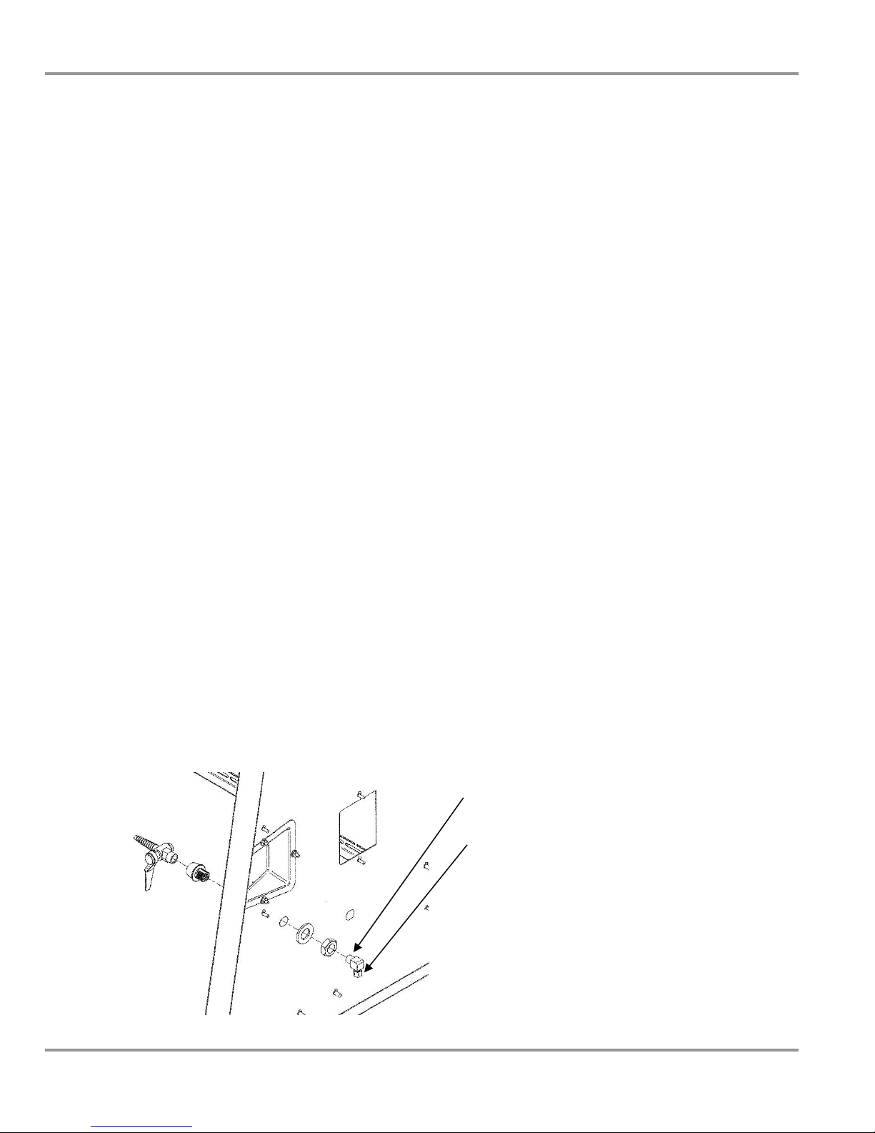
Figure 3-1
Connecting the Biosafety Cabinet to Utility
Service Lines
Note: Some models have a solenoid valve connected to the service valve on
the right side, rear position. The solenoid prevents gas from flowing to the
service valve when the unit blower is off. It is the only service valve position
that can be fitted with a solenoid valve. Connect the gas service to the
solenoid valve.
The service lines (if any) should be connected to the tube fitting(s) on the
outside of the liner wall as shown in Figure 3-1. To install the tubing, follow
these steps:
1. Ensure that the tubing is ¼ inch O.D., soft metal, and that the end has
been completely deburred.
2. Route the tubing from the rear of the cabinet, ensuring that it will line up
with the slot in the back of the side panel. The slot is located from 8 ¾ to
11 ¼ inches (222 to 288 mm) from the bottom of the cabinet.
Note: Make sure that the tube routing will not contact any electrical wires.
DO NOT loop service line tubing within the side panels of the cabinet.
3. Make sure that the nut on the tube fitting is loose, but do not remove it.
Look inside the fitting to make sure the tube ferrule is there.
4. Push the tube into the fitting until it is properly seated. The tube will go
approximately ¾ inch (19 mm) into the fitting.
5. Tighten the tube fitting nut hand tight and then, using a 7/16-inch wrench,
tighten it at least ¾ turn more.
6. Close the service valve in the biosafety cabinet and then slowly open the
shutoff valve on the service valve. Test all fittings for leakage. Tighten
the tube nut slightly if needed.
Tube fitting
Tube fitting nut
Product Service 1-800-522-7658

Chapter 3: Getting Started
13
Original instructions
Optional Exhaust Connection Requirements
Certain applications such as working with odorous products or volatile toxic
materials will require the connection of the biosafety cabinet to an exhaust
system.
Note: The Axiom exhaust connection includes an integral inlet relief valve,
which functions as a one-way, or check valve. During operation, the exhaust
system draws all of the cabinet’s exhaust air, plus a volume of room air
through the relief valve into the exhaust duct. The inlet relief valve functions
as a “shock absorber” allowing the cabinet to maintain optimal inflow during
changes in room air pressure.
Note: Because the Axiom cabinet has an integral exhaust fan, the vacuum
requirements of the exhaust system will be much lower than existing Type B
units. Please see the volume and vacuum requirements in Table 2-1, in If you
intend to connect the biosafety cabinet to an exhaust system: in Chapter 2:
Prerequisites
Note: If the research involves the use of toxic compounds or volatile
materials, contact the facility’s safety officer or Labconco to ensure that the
biosafety cabinet and its exhaust system are compatible with the materials
you will be working with.
Product Service 1-800-522-7658
Chapter 3: Getting Started
14
Original instructions
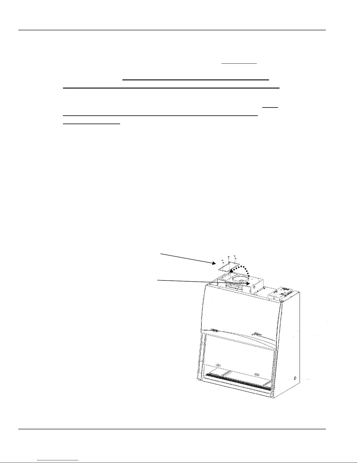
Figure 3-2
Exhaust Connection Configuration
Note: The Axiom is configured at the factory to operate unconnected to an
exhaust system. When operating in this mode, the cabinet ignores the inlet
relief valve position. If you intend to connect the cabinet to an exhaust
system, YOU MUST RECONFIGURE IT FOR THIS INSTALLATION.
Note: If the Axiom is connected to an exhaust system, and you choose to
disconnect it, to exhaust its HEPA-filtered air back into the laboratory, YOU
MUST RECONFIGURE IT FOR THIS INSTALLATION. These
instructions follow.
Connecting the Axiom to an Exhaust System
a) Mechanical configuration
1. Using an appropriate ladder or platform, remove the exhaust
cover panel(s) on the top right side of the exhaust cover, and
install them over the hole(s) on the left side. Hand tighten the
wing nuts to secure it, as shown in figure 3-2.
2. Connect the Axiom’s connection collar to the exhaust system,
ensuring the connection meets all appropriate codes and
regulations.
Exhaust cover installed over
exhaust outlet in left side of cover
top
Exhaust cover removed from the
right side of cover top
Product Service 1-800-522-7658
Chapter 3: Getting Started
15
Original instructions
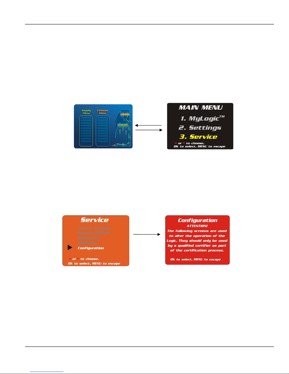
b) Electronic configuration
Keypad operations are shown as blue bold italic. Menu screen selections are
shown as green italics.
1. With the unit in operation, access the menu by pressing the Menu
button. The display panel will show the first level menu. Select
Service menu by pressing the ▲ or ▼ buttons until the Service is
highlighted. Press OK to accept that option, or press Menu to return
to the previous menu level.
Menu
Display Mode Menu Mode
Selecting the Configuration Menu
2. Using the ▲ and ▼ buttons on the touchpad, highlight the
Configuration option-it will be highlighted when selected. Press OK
and you will get an Attention screen, advising you the following
screens may alter the operation of the Axiom. Press OK to continue:
OK
Product Service 1-800-522-7658
Chapter 3: Getting Started
16
Original instructions
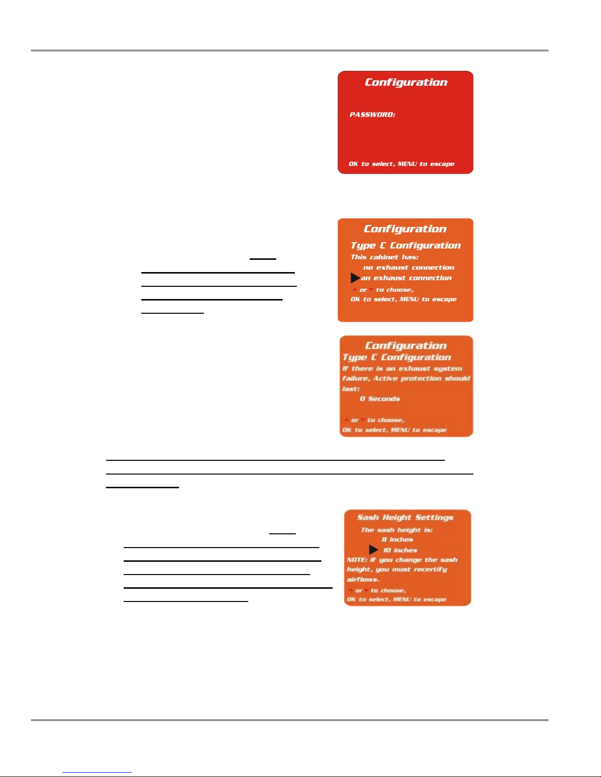
3. The screen will now prompt you for the
password; it is:
Light
UV Light
Timer
Timer
OK
Note: Any other key sequence will return you to the Attention screen.
4. The first screen allows you to select
whether the Axiom is connected to an
exhaust system or not. IT IS
CRITICAL THAT THE THIS
CABINET HAS AN EXHAUST
CONNECTION OPTION IS
SELECTED. Press OK to continue.
5. The second screen allows you to set
how long the blowers in the Axiom will
continue to operate in the event of an
exhaust system failure. The interval can
be programmed from 0-300 seconds.
Note: Consult with your facility’s safety officer or Labconco to help
establish how long the Axiom should continue to operate after an exhaust
system failure.
6. The third screen allows you to set the sash
height at either 8 or 10 inches. IT IS
CRITICAL THAT THE YOU LEAVE
THE SASH HEIGHT AS IT WAS SET
AT THE FACTORY, UNLESS YOU
WISH TO RECERTIFY THE CABINET
AT ITS NEW SETTING.
Product Service 1-800-522-7658
 Loading...