

Page 1

User’s Manual
Purifier®XT Clean Benches
Models
32000 Series
To receive important product updates,
complete your product registration card
online at register.labconco.com
Labconco Corporation
8811 Prospect Avenue
Kansas City, MO 64132-2696
800-821-5525, 816-333-8811
FAX 816-363-0130
E-MAIL labconco@labconco.com
HOME PAGE www.labconco.com
Please read the User’s Manual before operating the equipment.
Page 2

Copyright © 2013 Labconco Corporation. All rights reserved.
The information contained in this manual and the accompanying products are copyrighted and all rights
reserved by Labconco Corporation. Labconco Corporation reserves the right to make periodic design
changes without obligation to notify any person or entity of such change.
Warranty
Labconco provides a warranty on all parts and factory workmanship. The warranty includes areas of
defective material and workmanship, provided such defect results from normal and proper use of the
equipment.
The warranty for all Labconco products will expire one year from date of installation or two years
from date of shipment from Labconco, whichever is sooner, except the following;
• Purifier® Logic® Biological Safety Cabinets and PuriCare® Lab Animal Research Stations
carry a three-year warranty from date of installation or four years from date of shipment from
Labconco, whichever is sooner.
• SteamScrubber® & FlaskScrubber® Glassware Washers carry a two-year warranty from date
of installation or three years from date of shipment from Labconco, whichever is sooner.
• Blood Drawing Chairs carry a ten year warranty.
• Carts carry a lifetime warranty.
• Glassware is not warranted from breakage when dropped or mishandled.
This limited warranty covers parts and labor, but not transportation and insurance charges. In the
event of a warranty claim, contact Labconco Corporation or the dealer who sold you the product. If
the cause is determined to be a manufacturing fault, the dealer or Labconco Corporation will repair or
replace all defective parts to restore the unit to operation. Under no circumstances shall Labconco
Corporation be liable for indirect, consequential, or special damages of any kind. This statement may
be altered by a specific published amendment. No individual has authorization to alter the provisions
of this warranty policy or its amendments. Lamps and filters are not covered by this warranty.
Damage due to corrosion or accidental breakage is not covered.
Returned or Damaged Goods
Do not return goods without the prior authorization from Labconco. Unauthorized returns will not be
accepted. If your shipment was damaged in transit, you must file a claim directly with the freight carrier.
Labconco Corporation and its dealers are not responsible for shipping damages.
The United States Interstate Commerce Commission rules require that claims be filed with the delivery
carrier within fifteen (15) days of delivery.
Limitation of Liability
The disposal and/or emission of substances used in connection with this equipment may be governed by
various federal, state, or local regulations. All users of this equipment are required to become familiar with
any regulations that apply in the user’s area concerning the dumping of waste materials in or upon water,
land, or air and to comply with such regulations. Labconco Corporation is held harmless with respect to
user’s compliance with such regulations.
Contacting Labconco Corporation
If you have questions that are not addressed in this manual, or if you need technical assistance, contact
Labconco’s Customer Service Department or Labconco’s Product Service Department at 1-800-821-5525
or 1-816-333-8811, between the hours of 7:00 a.m. and 6:00 p.m., Central Standard Time.
Part #3207700, Rev. A
ECO H572
Page 3

T
AABBLLEE
T
CHAPTER 1: INTRODUCTION 1
About This Manual 1
Typographical Conventions 3
CHAPTER 2: PREREQUISITES 4
Location Requirements 5
Electrical Requirements 6
Service Line Requirements 6
Space Requirements 7
CHAPTER 3: GETTING STARTED 8
Unpacking Your Clean Bench 9
Clean Bench Components 9
Removing the Shipping Skid 10
Securing the Purifier XT Clean Bench 13
Initial Certification 14
Moving XT Clean Bench through Tight Doorway 16
CHAPTER 4: THEORY OF OPERATION AND
HEPA Filters 19
Laminar Airflow 21
Motor/Blower 21
Speed Control 22
Safety Precautions 22
CHAPTER 5: USING YOUR XT CLEAN BENCH 25
Starting the Clean Bench 25
Use of the Clean Bench 26
O
O
SAFETY PRECAUTIONS 19
FF
C
C
OONNTTEENNTTSS
Page 4

CHAPTER 6: MAINTAINING YOUR MEDIA
PREP CLEAN BENCH 28
Routine Maintenance Schedule 29
Service Operations 30
Resetting the Circuit Breaker 30
Changing the Prefilter 30
Speed Control Adjustment 31
Diffuser Removal 32
HEPA Filter Replacement 32
Motor/Blower Service 33
Motor/Blower Replacement 34
Storage 35
CHAPTER 7: TROUBLESHOOTING 36
APPENDIX A: XT CLEAN BENCH COMPONENTS 37
APPENDIX B: DIMENSIONS 39
APPENDIX C: XT CLEAN BENCH SPECIFICATIONS 40
Electrical Data 40
Motor Specifications 40
Environmental Conditions 41
Wiring Diagrams 42
APPENDIX D: XT CLEAN BENCH ACCESSORIES 43
Ergonomic Chair with Armrests 43
Adjustable Footrest 43
APPENDIX E: QUICK CHART FOR THE CLEAN BENCH 44
DECLARATION OF CONFORMITY 45
Page 5

C
HHAAPPTTEERR
C
I
NNTTRROODDUUCCTTIIOONN
I
Congratulations on your purchase of a Labconco Purifier® XT Clean Bench.
Your XT Clean Bench is designed to protect your product from particulate matter
contamination.
The XT Clean Bench offers many features to enhance safety, performance and
ergonomics. To take full advantage of them, please acquaint yourself with this
manual and keep it handy for future reference. If you are unfamiliar with how
clean benches operate, please review Chapter 4: Theory of Operation and Safety
Precautions before you begin working in the bench. Even if you are an
experienced clean bench user, please review Chapter 5: Using Your XT Clean
Bench; it describes your XT Clean Bench’s features so that you can use it
efficiently.
1
1
About This Manual
This manual is designed to help you learn how to install, use, and maintain your
XT Clean Bench. Instructions for installing optional equipment on your bench
are also included.
Chapter 1: Introduction provides a brief overview of the XT Clean Bench,
explains the organization of the manual, and defines the typographical
conventions used in the manual.
Chapter 2: Prerequisites explains what you need to do to prepare your site before
you install your XT Clean Bench. Electrical and service requirements are
discussed.
Product Service 1-800-522-7658
1
Page 6

Chapter 1: Introduction
Chapter 3: Getting Started contains the information you need to properly unpack,
inspect, install, and certify your XT Clean Bench.
Chapter 4: Theory Of Operation And Safety Precautions explains how a clean
bench operates and the appropriate precautions you should take when using the
bench.
Chapter 5: Using Your XT Clean Bench discusses the basic operation of your
bench. Information on how to prepare, use and shut down your XT Clean Bench
is included.
Chapter 6: Maintaining Your XT Clean Bench explains how to perform routine
maintenance on your XT Clean Bench. Information on how to safely disinfect the
interior of your bench is included.
Chapter 7: Troubleshooting contains a table of problems you may encounter
while using your clean bench including the probable causes of the problems and
suggested corrective actions.
Appendix A: XT Clean Bench Components contains labeled diagrams of all of the
components of the XT Clean Bench.
Appendix B: Dimensions contains comprehensive diagrams showing all of the
dimensions for the XT Clean Bench.
Appendix C: XT Clean Bench Specifications contains the electrical requirements
for the XT Clean Bench. Wiring diagrams for both the 115V and 230V units are
also included.
Appendix D: XT Clean Bench Accessories lists the part number and descriptions
of all of the accessories available for your clean bench.
Appendix E: Quick Chart for the Clean Bench provides useful operating
specifications.
2
Product Service 1-800-522-7658
Page 7
!
)
Chapter 1: Introduction
Typographical Conventions
Recognizing the following typographical conventions will help you understand
and use this manual:
• Book, chapter, and section titles are shown in italic type (e.g., Chapter 3:
Getting Started).
• Steps required to perform a task are presented in a numbered format.
• Comments located in the margins provide suggestions, reminders, and
references.
• Critical biosafety information is presented in boldface type in paragraphs that
are preceded by the biosafety icon. Failure to comply with the information
following a biosafety icon may result in illness or death.
• Critical information is presented in boldface type in paragraphs that are
preceded by the exclamation icon. Failure to comply with the information
following an exclamation icon may result in injury to the user or permanent
damage to your XT Clean Bench.
• Critical information is presented in boldface type in paragraphs that are
preceded by the wrench icon. These operations should only be performed by
a trained certifier or contractor. Failure to comply with the information
following a wrench icon may result in injury to the user or permanent damage
to your XT Clean Bench.
• Important information is presented in capitalized type in paragraphs that are
preceded by the pointer icon. It is imperative that the information contained
in these paragraphs be thoroughly read and understood by the user.
Product Service 1-800-522-7658
3
Page 8

C
HHAAPPTTEERR
C
P
RREERREEQQUUIISSIITTEESS
P
Before you install your XT Clean Bench, you need to prepare your site for
installation. Carefully examine the location where you intend to install your
bench. You must be certain that the area is level and of solid construction, and a
wall is nearby to secure the back of the XT Clean. In addition, a dedicated source
of electrical power must be located near the installation site.
Carefully read this chapter to learn:
• the location requirements for your installation site.
• the electrical power requirements for your installation site.
• the service line requirements for your installation site.
• the space requirements for your installation site.
Refer to Appendix C: XT Clean Bench Specifications for complete XT Clean
Bench electrical and environmental conditions, specifications and requirements.
2
2
4
Product Service 1-800-522-7658
Page 9
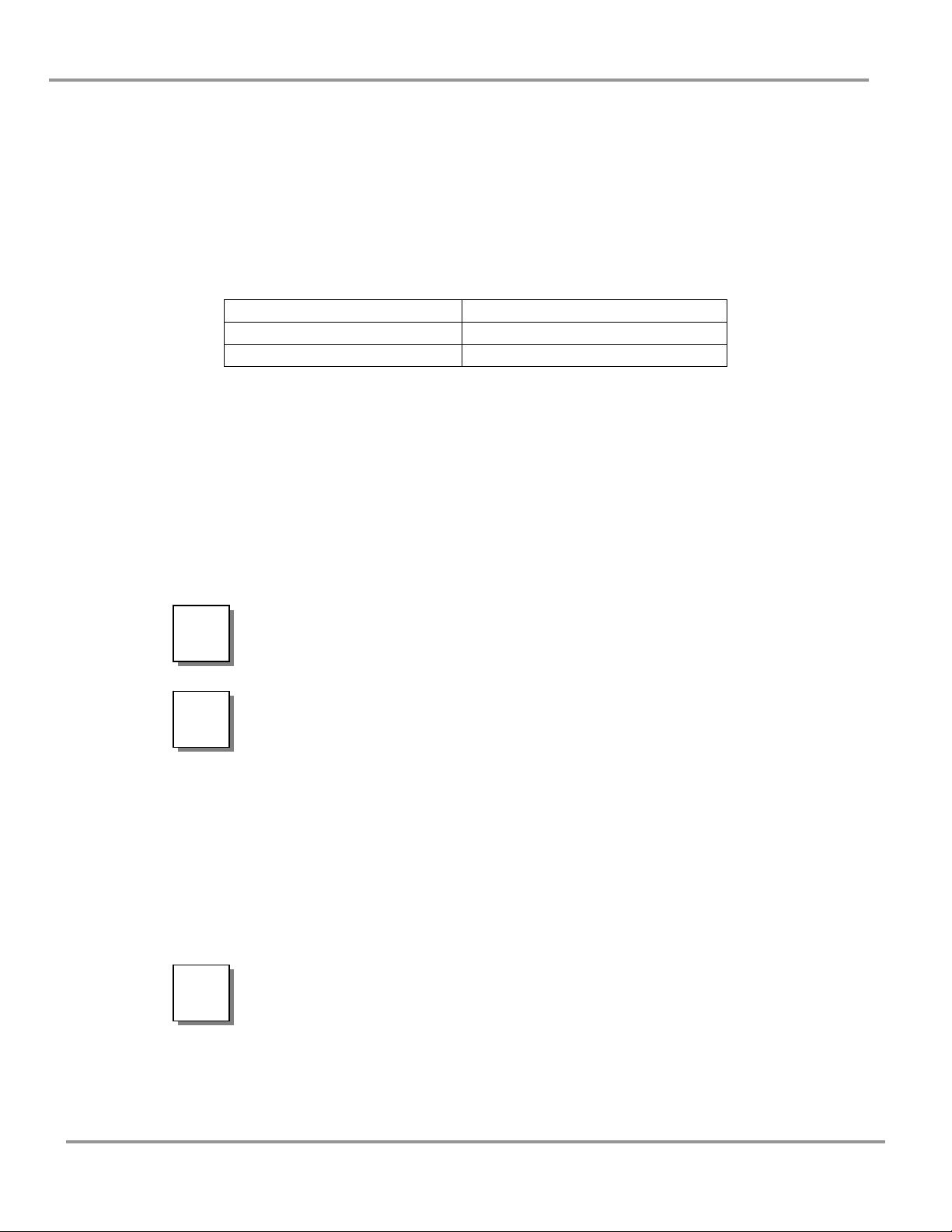
Location Requirements
The Purifier XT Clean Bench should be located away from traffic
!
!
patterns, doors, fans, ventilation registers, fume hoods and any
other air-handling device that could disrupt its airflow patterns.
All windows in the room should be closed. Figure 2-1 shows the
optimum location for the bench.
L’hotte à flux laminaire Purifier doit etre située à l’écart de la
circulation, des portes, des ventilateurs, des registres de ventilation,
des sorbonnes et n’importe quel dispositif de traitement d’air qui
peut interrompre le circuit du courant d’air. Toutes les fênetres de
la chambre doit etre fermée. La figure 2-1 montre l’emplacement
optimal pour l’hotte.
Figure 2-1
Chapter 2: Prerequisites
Product Service 1-800-522-7658
5
Page 10
Chapter 2: Prerequisites
Electrical Requirements
The different Purifier XT Clean Bench models have the following electrical
requirements:
All Purifier XT Clean Benches with model numbers ending in -00 are designed
for operation at 115 volts, 60 Hz, alternating current. XT Clean Benches with
model numbers ending in -01 through -04 are designed for operation at 230 volts,
50/60 Hz alternating current. A dedicated outlet with a circuit breaker rated at 20
amps should be located as close as possible to the right, rear side of the bench in
its final location. If your electrical outlet is distant from this location, contact
Labconco’s Product Service Department for information on longer cords.
32000 -01, -02, -03, -04 230 VAC, 50/60 Hz, 6 Amps
!
!
Model # Requirements
32000 -00 115 VAC, 60 Hz, 10 Amps
Do not use any detachable power cord that is not adequately
rated for the unit.
Ne pas utliser un fil électrique amovible qui n’est pas du tension
nominale de l’appareil.
Table 2-1
Service Line Requirements
All service lines to the XT Clean Bench should be quarter inch outside diameter,
metal, and equipped with an easily accessible shut-off valve should disconnection
be required. If the service line pressure exceeds 40 PSI, it must be equipped with
a pressure regulator to reduce the line pressure.
The use of flammable gases or solvents should be avoided in
!
6
the clean bench. Open flames in the cabinet will disrupt the
laminar airflow in the bench. If you feel that your procedure
requires the use of an open flame or flammable materials,
contact the appropriate safety official.
Product Service 1-800-522-7658
Page 11

The use of air or gases under high pressure should be
considered carefully as they may seriously disrupt the airflow
patterns in the bench.
L’utilisation de gaz inflammables ou de solvants dans l’hotte doit
!
être évitée. Les flammes nues interromprent le circuit du courant
d’air laminaire dans l’hotte. Si vous estimez que votre procedure
exige l’utilisation d’une flamme nue ou des matériaux
inflammables, Prenez contact avec un officiel de sécurité
competent.
Prenez en considération l’uilisation d’air ou de gaz sous haute
pression car il peut interrompre gravement le circuit du courant
d’air dans l’hotte.
Space Requirements
Chapter 2: Prerequisites
The dimensions for the different models are shown in Appendix B: XT Clean
Bench Dimensions.
The XT Clean Bench is designed to house tall media preparation machines or
other large equipment, and therefore is taller in height. The XT Clean Bench
must be properly secured to a wall using the bracket and lashing strap provided to
tie the back of the bench to an adjacent wall. Instructions for attaching the
bracket and lashing strap to the bench and adjacent wall are located in Chapter 3:
Getting Started.
Product Service 1-800-522-7658
7
Page 12
C
HHAAPPTTEERR
C
G
EETTTTIINNGG
G
Now that the site for your XT Clean Bench is properly prepared, you are ready to
unpack, inspect, install, and certify your unit. Read this chapter to learn how to:
• unpack and move your bench.
• set up the bench.
• connect the electrical supply source.
• connect the service lines.
• arrange certification of your XT Clean Bench.
Depending upon which model you are installing, you may need common
plumbing and electrical installation tools in addition to two 1/2" wrenches, a
7/16" wrench, a flat-blade screwdriver, a Phillips screwdriver, and a carpenter
level to complete the instructions in the chapter.
The Purifier XT Clean Bench models weigh between 400 – 600
lbs. (182-272 kg). The carton skid allows for lifting with a
!
!
mechanical lift truck or floor jack.
Les modèles de hotte à flux laminaire Purifier XT Clean Bench
pèsent entre 400 à 600 lbs (182-272 kg). Le carton permet le
levage avec un chariot élévateur á fourche.
S
S
3
3
TTAARRTTEEDD
8
Product Service 1-800-522-7658
Page 13
The United
States Interstate
Commerce
Commission
rules require
that claims be
filed with the
delivery carrier
within fifteen
(15) days of
delivery.
Chapter 3: Getting Started
Unpacking Your Clean Bench
Carefully unpack your Purifier XT Clean Bench and inspect it for damage that
may have occurred in transit. If your unit is damaged, notify the delivery carrier
immediately and retain the entire shipment intact for inspection by the carrier.
DO NOT RETURN GOODS WITHOUT THE PRIOR
AUTHORIZATION OF YOUR DEALER AND LABCONCO.
)
Do not discard the carton or packing material for your clean bench until you have
checked all of the components and installed and tested the unit.
Do not remove the clean bench from its shipping skid until it is ready to be placed
into its final location. Move the unit by placing a flat, low dolly under the
shipping skid, or by using a floor jack.
!
!
UNAUTHORIZED RETURNS WILL NOT BE ACCEPTED.
IF YOUR BENCH WAS DAMAGED IN TRANSIT, YOU MUST
FILE A CLAIM DIRECTLY WITH THE FREIGHT CARRIER.
LABCONCO CORPORATION AND ITS DEALERS ARE NOT
RESPONSIBLE FOR SHIPPING DAMAGES.
Do not move the bench by tilting it onto a hand truck.
Ne pas déplacer l’hotte au moyen de incliner sur un diable.
Clean Bench Components
Labconco manufactures XT Clean Benches for operation on 115V or 230V. Each
of these benches is available in 3-foot models with work surface depths of 29”.
Locate the cabinet model you received in the following group of tables. Verify
that the components listed are present and undamaged.
Catalog # Description
3200000 Purifier XT Clean Bench, 115 VAC
3200001 to -04 Purifier XT Clean Bench, 230 VAC
Plus the Following:
Product Service 1-800-522-7658
9
Page 14
Chapter 3: Getting Started
Part # Component Description
3208000 Purifier Clean Bench Owner’s Manual CD
3952900 Strap, Lashing
3894400 Bracket, Tie-Down
1337100 Power Cord, 115V
Or (one of the following)
1338000 Power Cord, 230V United States
1332600 Power Cord, 230V United Kingdom
1336100 Power Cord, 230V Schuko
1332700 Power Cord, 230V China/Australia
If you did not receive one or more of the components listed for your clean bench,
or if any of the components are damaged, contact the Labconco Product Service
Department immediately for further instructions @ 1-800-821-5525.
Removing the Shipping Skid
LEAVE THE CLEAN BENCH ATTACHED TO ITS SHIPPING
)
After you verify the XT Clean Bench components, move your XT Clean Bench to
the location where you want to install it. Then, follow the steps listed below to
remove the shipping skid from your unit.
To remove the shipping skid:
1. Remove the plastic wrapping and packaging material from the bench.
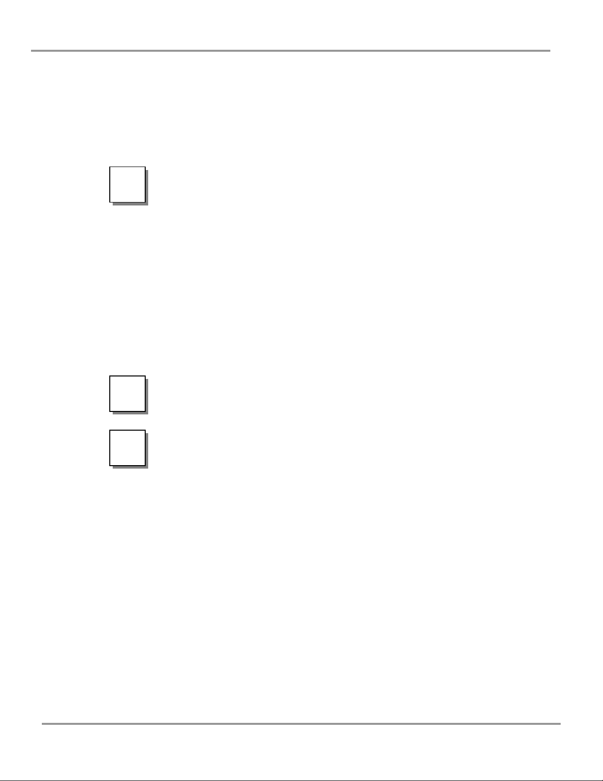
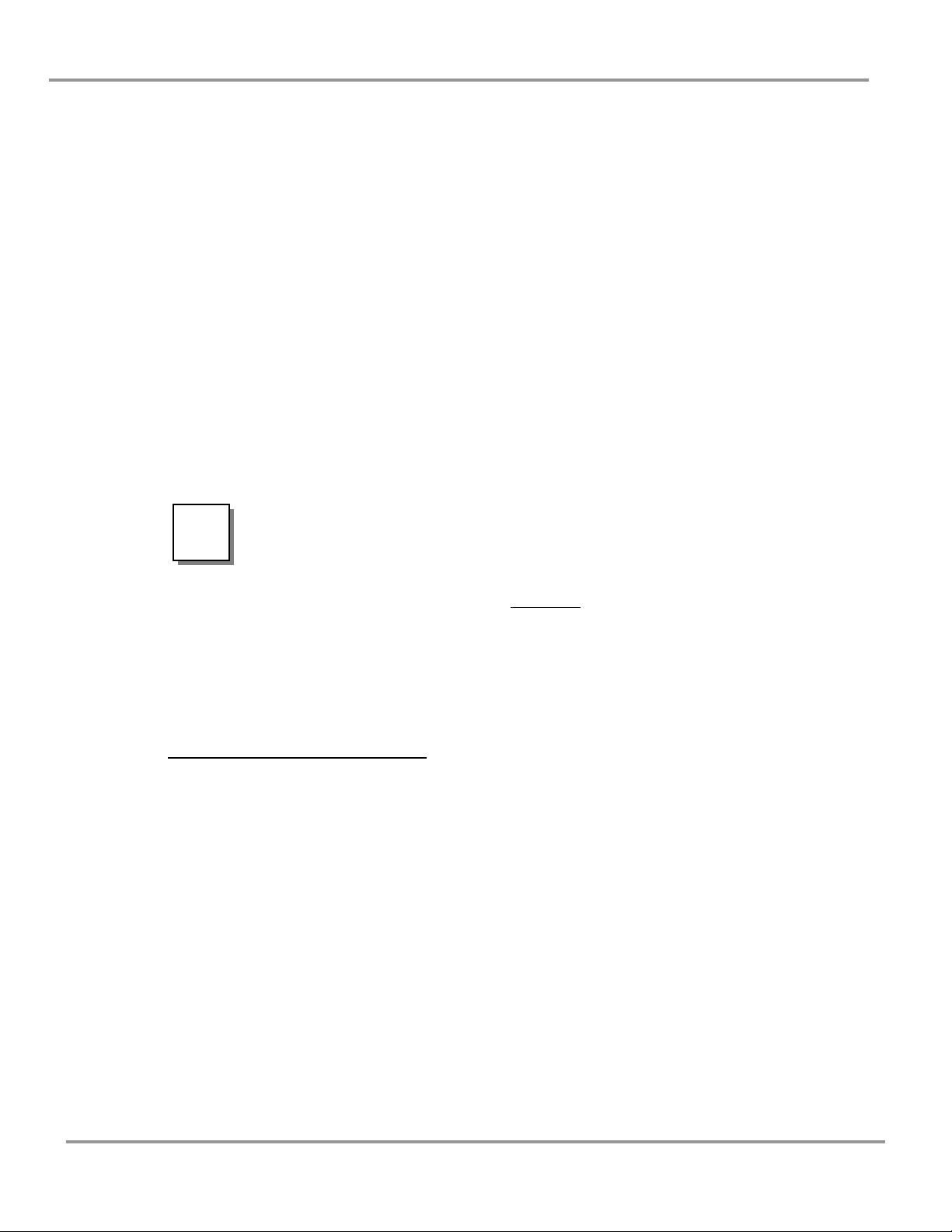
2. Remove and discard the three brackets holding the unit to the skid, as shown
in Figures 3-1a and 3-1b.
3. Lift clean bench off of shipping skid using a mechanical lift, forklift, or two
pallet jacks with boards slid underneath the clean bench spanning the two
pallet jacks.
4. Set the four legs to desired working height by removing the four bolts,
extending each leg and replacing each bolt and washers, secure acorn nut
firmly. The integrated stand has three working height options. The lowest
hole will set the worksurface height at 29.2”, and each higher hole raises that
height by 1.5”. To raise clean bench off of its legs, use mechanical lift, fork
lift, or pallet jack with boards as shown in Figure 3-2.
5. Once in final location, adjust leveling feet to ensure clean bench is level.
SKID UNTIL IT IS AS CLOSE TO ITS FINAL LOCATION AS
POSSIBLE. MOVE THE UNIT BY USING A SUITABLE
FLOOR JACK, OR BY PLACING A FURNITURE DOLLY
UNDERNEATH THE SKID. DO NOT MOVE THE BENCH BY
TILTING IT ONTO A HAND TRUCK.
10
Product Service 1-800-522-7658
Page 15
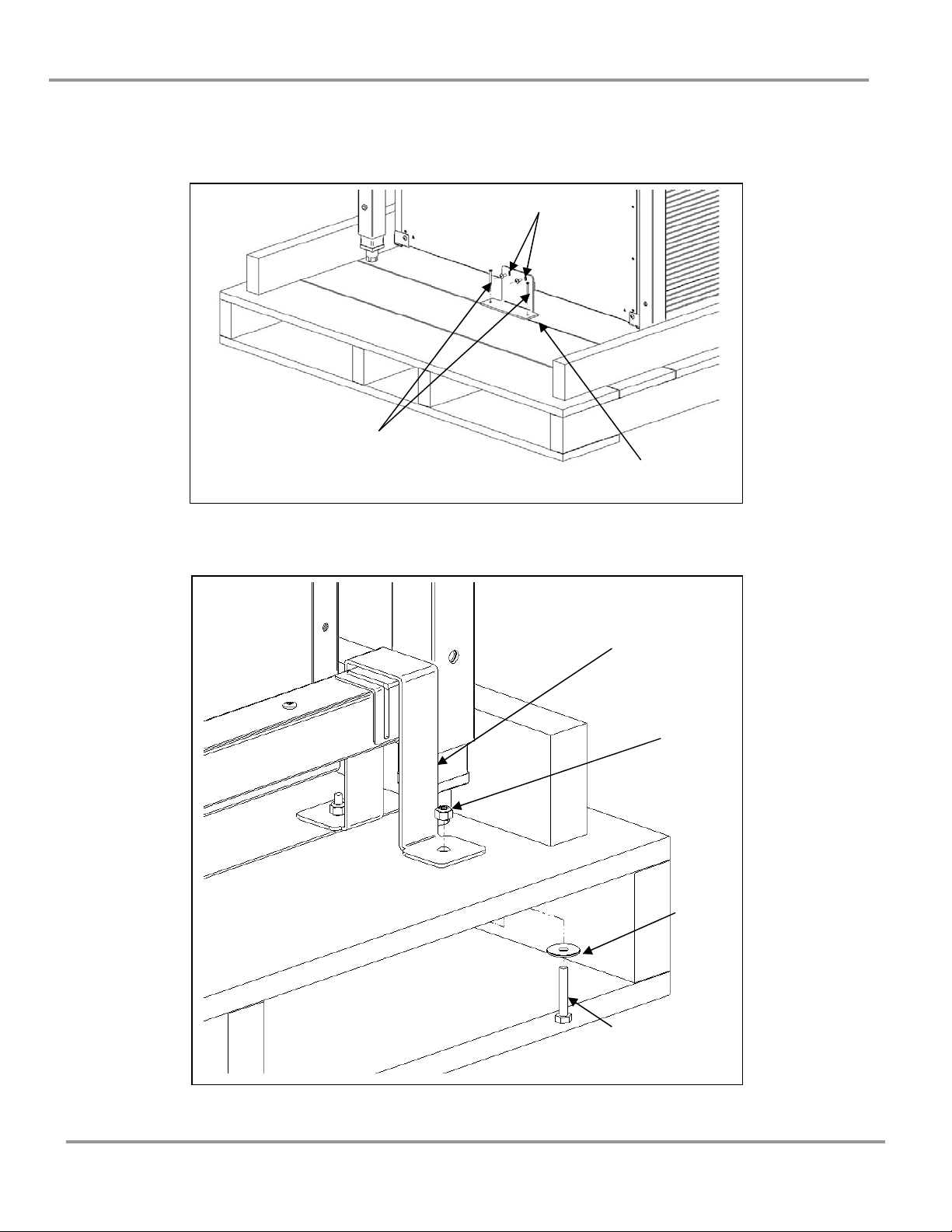
Figure 3-1a
Chapter 3: Getting Started
Cabinet screws (2)
Figure 3-1b
Wood screws (2)
Shipping
Bracket
Shipping
Bracket
(1 ea side)
Nut
(2 ea
side)
Product Service 1-800-522-7658
Washer
(2 ea
side)
Bolt
(2 ea side)
11
Page 16

Chapter 3: Getting Started
Figure 3-2
Bolt, Washers &
Acorn Nut (ea leg)
Support
Boards
Pallet Jack
12
Product Service 1-800-522-7658
Page 17

Chapter 3: Getting Started
Securing the Purifier XT Clean Bench
BEFORE USING THE CLEAN BENCH, IT MUST BE
PROPERLY SECURED TO A WALL OR STRUCTURAL
)
Obtain the following items from the box located on the Purifier XT Clean Bench
worksurface:
(1) Wall-Mount Bracket p/n 3894400
(2) Lashing Strap p/n 3952900
Follow the steps below to secure the clean bench to a wall or other significant
vertical structural building element.
To secure the clean bench:
1. Using proper screws, secure the Wall-Mount Bracket to the wall behind the
final position of the clean bench. Center bracket behind clean bench final
position, with the bracket approximately 68” (1700mm) off the floor. See
Figure 3-3 below.
2. Run the Lashing Strap through the slot in the Wall-Mount Bracket, then
through one of the slots on the back of the clean bench. Run the Lashing
Strap through the other slot on the back of the clean bench. Run the Lashing
Strap through the ratchet mechanism on the strap. See Figure 3-4 below.
3. Push the clean bench against the wall and cinch the Lashing Strap down.
Strap does not have to be tight, but slack should be minimal.
Figure 3-3
BEAM TO AVOID TIPPING OVER.
Wall
Secure
through both
holes to wall
Product Service 1-800-522-7658
Wall-Mount
Bracket
13
Page 18

Chapter 3: Getting Started
Figure 3-4
Back of
clean bench
Slot for
Lashing
Strap
Initial Certification
Prior to use, all Purifier XT Clean Benches should be certified by a qualified
certifier. Under normal operating conditions, the Purifier XT Clean Bench should
be recertified at least annually and when moved or serviced. The certifier should
perform the following tests, as recommended in Institute of Environmental
Sciences and Technology, IEST RP-CC0002.2:
• Airflow Velocity Test
• HEPA Filter Leak Test
• Introduction Leak Test/Backstreaming (when appropriate)
• Airborne Particle Count (when appropriate)
• Lighting Intensity Test (when appropriate)
• Noise Level Test (when appropriate)
• Vibration Test (when appropriate)
In addition, the following tests should also be performed at the user’s discretion:
• Electrical Leakage and Ground Circuit Resistance Test
• Measurement of Line Voltage and Current
• Smoke Test to determine airflow patterns
THE XT CLEAN BENCH USES A SELF-ADJUSTING ECM
MOTOR TO MAINTAIN AIRFLOW ACROSS THE WORK
)
AREA. THE SPEED CONTROL
14
Product Service 1-800-522-7658
Page 19

Chapter 3: Getting Started
ADJUSTMENT ESTABLISHES THE DESIRED FACE
VELOCITY (FPM), AND AS THE HEPA FILTERS LOAD, THE
MOTOR WILL SPEED UP TO MAINTAIN THE DESIRED
FACE VELOCITY. HAVE THE FACE VELOCITY CHECKED
AT LEAST ANNUALLY AS INDICATED IN CHAPTER 6:
MAINTAINING YOUR XT CLEAN BENCH. REPLACE HEPA
FILTERS WHEN FACE VELOCITY DROPS BELOW DESIRED
RANGE.
If you have any questions regarding certification agencies or need assistance in
locating one, contact Labconco’s Product Service Department at 1-800-821-5525.
Product Service 1-800-522-7658
15
Page 20

Chapter 3: Getting Started
Moving XT Clean Bench through Tight
Doorway
MAKE SURE THERE IS NO ALTERNATE DOORWAY OF
GREATER WIDTH. DISASSEMBLY OF UNIT INVOLVES
)
To remove the Side Windows:
1. Obtain a T20 Torx Head Driver Bit and electrical screwdriver or drill.
2. Unscrew all screws around both the right and left window frames as seen in
Figure 3-5a below. NOTE!!! Do NOT remove Screws next to a small cut-out
as seen in Figure 3-5b. Remove both side window assemblies.
SIGNIFICANT TIME AND LIFTING OF HEAVY
COMPONENTS.
Figure 3-5a
Side
Windows
Torx Screws
16
Product Service 1-800-522-7658
Page 21

Chapter 3: Getting Started
!
Figure 3-5b
Cut-outs
Leave the
screws by
cut-outs
The Top Window assembly is heavy. Lift & handle with care.
L’ensemble première fenêtre est lourd. Soulever et manipuler
avec precaution.
Product Service 1-800-522-7658
17
Page 22

Chapter 3: Getting Started
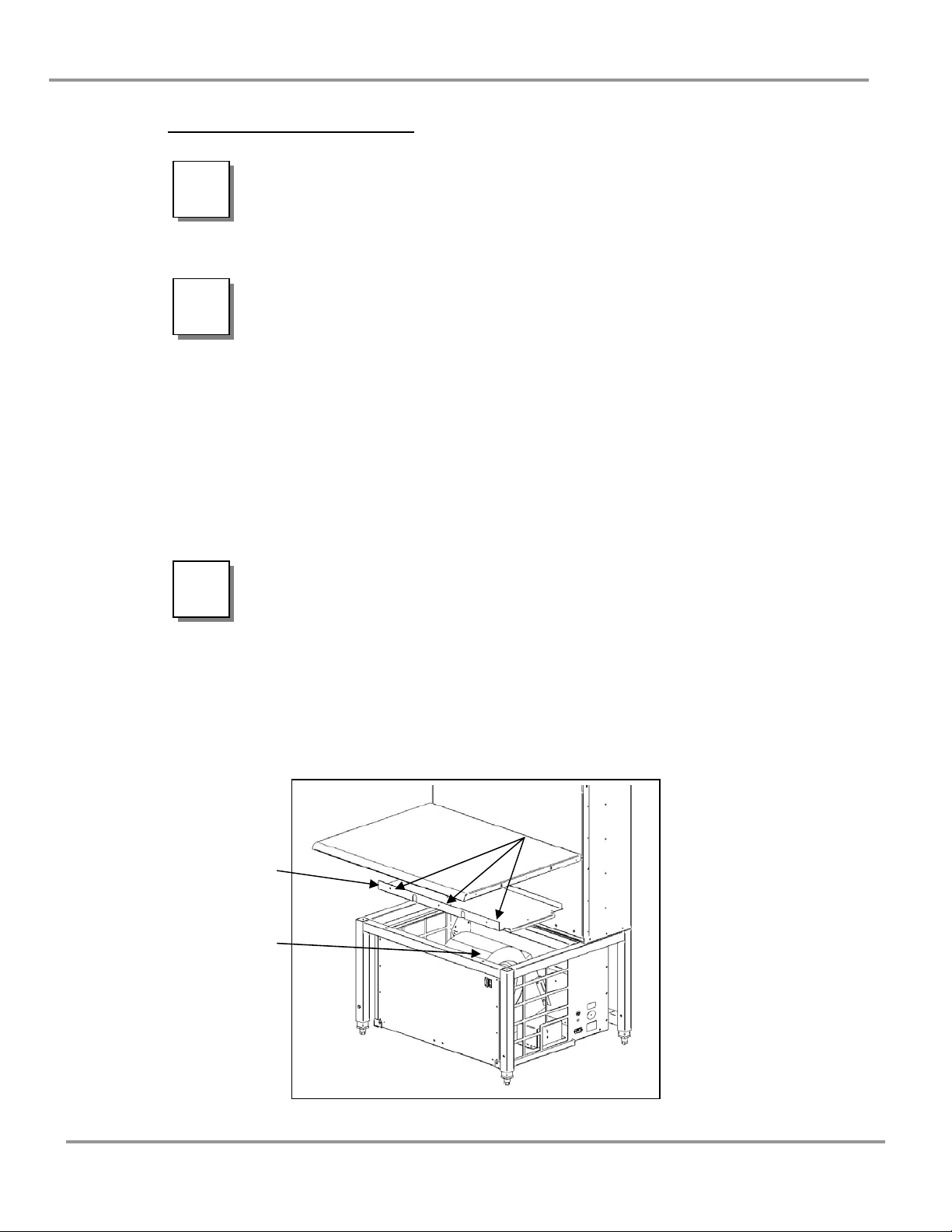
3. Remove the Torx Head Screws on top side and top back of unit to remove
Top Window as seen in Figure 3-5c.
4. Remove the two Bolts and Washers underneath Worksurface as shown in
Figure 3-5c.
5. Pull up on front edge of Worksurface, and then pull Worksurface out.
6. Reinstall components in reverse to reassemble the XT Clean Bench.
Figure 3-5c
Top
Window
Worksurface
Worksurface
Bolts & Washers
18
Product Service 1-800-522-7658
Page 23

C
HHAAPPTTEERR
C
T
HHEEOORRY
T
S
AAFFEETTYY
S
All clean benches operate using the following principles:
• Filtration and retention of particulates by High Efficiency Particulate Air
(HEPA) filter(s)
• Laminar airflow
The major components in a clean bench are:
• The HEPA filter
• The motor/blower to force air through the unit
• A speed control for the motor
HEPA Filters
Y
O
O
P
P
4
4
F
O
F
O
PPEERRAATTIIOONN
RREECCAAUUTTIIOONNSS
A
A
NNDD
HEPA filters are disposable, dry-type particulate filters. The filter material or media
is typically made of borosilicate microfibers that are made into a thin sheet, in a
process similar to the production of paper. This sheet is folded, or pleated to increase
its surface area. The pleats are held in place by aluminum diffusers or by beads of
glue that add rigidity to the media pack. The media pack is then set into a suitable
frame, and the perimeter sealed to the filter frame, as shown in Figure 4-1.
The HEPA filter media is very fragile. Do not touch or contact
!
Product Service 1-800-522-7658
the media surface. If you think the surface of a HEPA filter is
damaged, DO NOT USE THE BENCH. Have the HEPA filter
integrity tested by a qualified certifier before using the cabinet.
19
Page 24

Chapter 4: Theory of Operation and Safety Precautions
HEPA Filters are only effective against particulate material.
Gases will pass through the filter.
Le matériel du filtre HEPA est très fragile. Ne pas toucher ou
!
être en contact avec la surface du matériel. Si vous pensez que la
surface d’un filter HEPA est endommagé, NE PAS UTILISER
L’HOTTE. Faire tester l’intégrité du filter HEPA par un
certificateur qualifié avant d’utiliser l’hotte.
Filtres HPA ne sont efficaces que contre les matières
particulaires. Le gaz passe à travers du filtre.
Figure 4-1
Continuous
Sheet of Flat
Filter Medium
Glue Beads
Note - The HEPA Filters in the Purifier XT Clean Bench
are separatorless filters that utilize a series of glue beads to
hold the filter medium in place.
Filter
Frame
Adhesive bond
between Filter
Pack and Integral
Frame
20
Product Service 1-800-522-7658
Page 25

Chapter 4: Theory of Operation and Safety Precautions
Laminar Airflow
Laminar airflow is defined as the movement of a body of air in a single direction,
with a uniform velocity. In practice, the horizontal laminar flow of sterile air in
the clean bench flushes out any aerosol generated in the work area of the bench.
This sterile airflow maintains the sterility of sterile items inside the clean bench.
In order to be true laminar flow, a number of individual velocity test points (The
Velocity Profile) must be +/- 20 % of the average of all the test points. This is
shown graphically in Figure 4-2.
Figure 4-2
Motor/Blower
The motor/blower assembly pulls air through the prefilters on the bottom sides of
the bench, and flows through the HEPA filter, which then flows horizontally
through the work area.
Product Service 1-800-522-7658
21
Page 26

Chapter 4: Theory of Operation and Safety Precautions
Speed Control
The speed control should only be adjusted by a qualified
!
!
The speed control is an electronic circuit that allows the certifier to set the air face
velocity (fpm) by adjusting its voltage.
)
!
!
certifier.
Le contrôle de la vitesse doit être réglée uniquement par un
certificateur qualifié.
THE XT CLEAN BENCH USES A SELF-ADJUSTING ECM
MOTOR TO MAINTAIN AIRFLOW ACROSS THE WORK
AREA. THE SPEED CONTROL
ADJUSTMENT ESTABLISHES THE DESIRED FACE
VELOCITY (FPM), AND AS THE HEPA FILTERS LOAD, THE
MOTOR WILL SPEED UP TO MAINTAIN THE DESIRED
FACE VELOCITY. HAVE THE FACE VELOCITY CHECKED
AT LEAST ANNUALLY AS INDICATED IN CHAPTER 6:
MAINTAINING YOUR XT CLEAN BENCH. REPLACE HEPA
FILTERS WHEN FACE VELOCITY DROPS BELOW DESIRED
RANGE.
Never block or obstruct the air intake at the bottom sides of
the clean bench.
Ne jamais bloquer l’entrée d’air au dessus de l’hotte.
Safety Precautions
Because air from the work area is dispersed directly into the
laboratory, the Purifier XT Clean Bench should never be used
in conjunction with biohazardous material, toxins, or
radionuclides. The operator and qualified safety officer(s)
must carefully assess the risk associated with any operation
performed in a Clean Bench.
Étant donné que l’air de la zone de travail est dispersée
directement dans le laboratoire, l’hotte à flux laminaire Purifier
22
XT ne doit jamais être utilisé conjointment avec des matières
Product Service 1-800-522-7658
Page 27

!
!
Chapter 4: Theory of Operation and Safety Precautions
infectieuses, des toxins ou des radionucléides. L’opérateur et
l’oficiel de sécurité competent doivent soigneusement évaluer le
risque associé à tous les opérations effectuées dans un hotte à
flux laminaire.
The Purifier XT Clean Bench should be certified by a qualified
certification technician before its initial use. The clean bench
should be recertified whenever it is relocated, serviced, or at
least annually thereafter.
Some components of the Purifier XT Clean Bench should only
be serviced by a qualified certification technician. Ensure that
the unit is connected to electrical service in accordance with
local and national electrical codes. Failure to do so may create
a fire or electrical hazard. Do not remove or service any
electrical components without first disconnecting the clean
bench from electrical service.
Le Purifier Clean Bench doit être certifié par un technician de
certification qualifié avant la première utilization. L’hotte doit
être certifié à nouveau chaque fois qu’il est déplacé, reparé ou au
moins une fois par an par la suite.
Certains composants de la Purifier Clean Bench ne doit être
réparé que par un technician de certification qualifié. Assurezvous que l’appareil est connecté à un service électrique qui est en
conformité avec les règlements de sécurité locaux et nationaux.
Non-respect des règlements peut causer un incendie ou autre
danger électrique. Ne pas enlever ou réparer des compasants
électriques sans débrancher l’hotte du service électrique.
Avoid the use of flammable gases or solvents in the clean
bench. An open flame should NOT be used in the clean bench.
Open flames may disrupt the airflow patterns in the Clean
Bench. Gases under high pressure should not be used in the
Purifier Clean Bench, as they may disrupt the airflow patterns.
The surface of the HEPA filter is fragile and should not be
touched. Care must be taken to avoid puncturing the HEPA
filter during installation or normal operation. If you suspect
that the HEPA filter has been damaged, DO NOT use the clean
bench; contact a local certification agency or Labconco at 800821-5525 for recertification information.
Évitez l’utilisation de gaz inflammables ou de solvants pour
nettoyer l’hotte. Une flamme nue ne doit PAS être utilisé dans
l’hotte. Flammes nues peuvent interrompre le circuit du courant
Product Service 1-800-522-7658
23
Page 28

Chapter 4: Theory of Operation and Safety Precautions
d’air dams l’hotte. Gaz sous haute pression ne doit pas être
utilisé dans l’hotte, car il peut interrompre le ciruit du courant
d’air dans l’hotte.
La surface du filtre HEPA est fragile et ne doit pas être touchée.
Faites attention de ne pas percer le filtre HEPA lors de
l’installtion ou le fonctionnement normal. Si vous pensez que le
filtre HEPA a été endommagé. NE PAS utiliser l’hotte, prenez
contact avec une agence de certification locale ou avec Labconco
à 800-821-5525 pour de plus amples informations sur la
recertification.
THE HEPA FILTER IN THE PURIFIER XT CLEAN BENCH
WILL GRADUALLY ACCUMULATE AIRBORNE
)
)
PARTICULATE MATTER FROM THE ROOM. THE RATE OF
ACCUMULATION WILL DEPEND UPON THE
CLEANLINESS OF THE ROOM AIR, THE AMOUNT OF TIME
THE CLEAN BENCH IS OPERATING AND THE NATURE OF
WORK BEING DONE IN THE CLEAN BENCH. IN TYPICAL
INSTALLATIONS AND USAGE, THE HEPA FILTERS WILL
LAST TWO TO FIVE YEARS BEFORE REQUIRING
REPLACEMENT.
PROPER OPERATION OF THE CLEAN BENCH DEPENDS
LARGELY UPON THE CLEAN BENCH’S LOCATION AND
THE OPERATOR’S WORK HABITS. CONSULT THE
Installation AND Normal Operation SECTIONS OF THIS
MANUAL FOR FURTHER DETAILS.
WIPE THE INTERIOR SURFACES OF THE CLEAN BENCH
WITH STAINLESS STEEL CLEANER OR 70% ETHANOL.
DO NOT USE ABRASIVE CLEANERS, BLEACH OR
SOLVENTS, AS THEY MAY DAMAGE THE WORK
SURFACE.
WHEN SURFACE DISINFECTING THE PURIFIER:
• AVOID SPLASHING THE DISINFECTING SOLUTION ON
SKIN OR CLOTHING.
• ENSURE ADEQUATE VENTILATION.
• CAREFULLY FOLLOW THE MANUFACTURER’S SAFETY
INSTRUCTIONS WHEN HANDLING DISINFECTANTS AND
ALWAYS DISPOSE OF DISINFECTING SOLUTIONS IN
ACCORDANCE WITH LOCAL AND NATIONAL LAWS.
24
Product Service 1-800-522-7658
Page 29

C
HHAAPPTTEERR
C
U
SSIINNG
U
B
EENNCCHH
B
Starting the Clean Bench
Before starting the Clean Bench, plug the power cord in and make sure the Circuit
Breaker is depressed. To turn on the Clean Bench, push the blower switch to the
“ON” position, as shown in Figure 5-1.
Figure 5-1
G
Y
Y
OOUURR
5
5
X
T
X
T
C
C
LLEEAANN
On/Off
Switch
Product Service 1-800-522-7658
Circuit Breaker
Power Cord Plug-in
25
Page 30

Chapter 5: Using Your XT Clean Bench
Use of the Clean Bench
Planning
Start-Up
Loading Materials and Equipment
Work Techniques
Final Purging
• Thoroughly understand procedures and equipment before beginning work.
• Arrange for minimal disruptions, such as room traffic or entry into the
room, while the clean bench is in use.
• Turn on clean bench blower.
• Check the prefilter for obstructions.
• Wipe down the interior surfaces of the clean bench with stainless steel
cleaner or 70% ethanol. DO NOT use abrasive cleaners, bleach or
solvents, as they may damage the work surface of the clean bench.
• Allow the clean bench to operate undisturbed for 5 to 15 minutes before
loading materials.
• Wear long sleeved lab coat with knit cuffs and over-the-cuff rubber
gloves. Use protective eyewear.
• Only load the materials required for the procedure. Do not overload the
clean bench.
• Do not obstruct the air diffuser.
• Large objects should not be placed close together.
• After loading the clean bench, wait 2 to 3 minutes to purge airborne
contaminants from the work area.
• Keep all materials at least 4 inches inside of the clean bench and perform
all contaminated operations as far to the front of the work area as possible.
• Perform sterile operations as far to the rear of the work area as possible.
• Segregate all clean and contaminated materials in the work area.
• Arrange materials to minimize the movement of contaminated materials
into clean areas.
• Keep all discarded contaminated material to the front of the clean bench.
• Avoid moving materials or the operator’s hands and arms in and out of the
work area during use.
• Avoid the use of an open flame.
• Use proper aseptic technique. – “Sterile Air First”
• Avoid using techniques or procedures that disrupt the airflow patterns of
the clean bench.
• Upon completion of work, the clean bench should be allowed to operate
for 2 to 3 minutes undisturbed, to purge airborne contaminants from the
work area.
26
Product Service 1-800-522-7658
Page 31

Chapter 5: Using Your XT Clean Bench
Wipe-Down
• Wipe down the interior surfaces of the clean bench with stainless steel
cleaner or 70% ethanol and allow to dry.
Shutdown
• Turn off the clean bench blower.
Product Service 1-800-522-7658
27
Page 32

C
HHAAPPTTEERR
C
M
C
Now that you have an understanding of how to work in the XT Clean Bench, we
will review the suggested maintenance schedule and the common service
operations necessary to maintain your clean bench for peak performance.
AAIINNTTAAIINNIINNG
M
LLEEAANN
C
Many of the service operations should be performed only by
!
!
trained and experienced certification technicians. DO NOT
attempt to perform these operations if you are not properly
trained. The service operations that require qualified certifiers
are preceded by the wrench icon.
La plupart des operations d’entretien doivent être effectués
uniquement par des techniciens de certification qualifiés et
expérimentés. NE PAS tenter effectuer ces operations si vous
n’êtes pas bien formés. Les operations de service qui exigent des
certificateurs qualifies sont précédés par l’icône de la clé.
6
6
B
EENNCCHH
B
G
Y
Y
OOUURR
X
X
T
T
28
Product Service 1-800-522-7658
Page 33

Chapter 6: Maintaining Your XT Clean Bench
Routine Maintenance Schedule
Under normal operation, your Purifier XT Clean Bench will require little routine
maintenance. The following schedule is recommended:
Weekly
• Wipe down the interior surfaces of the clean bench with stainless steel
cleaner or 70% ethanol and allow to dry.
• Using a damp cloth, clean the exterior surfaces of the clean bench,
particularly the front and top of the clean bench to remove any
accumulated dust.
Monthly (or more often as required)
• Check all service valves, if so equipped, for proper operation.
• Check the prefilters and replace if necessary. The prefilters should be
replaced at least quarterly.
• All weekly activities.
Quarterly
• Replace the prefilter. See Appendix A: XT Clean Bench Components for
• All monthly activities.
Annually
• Have the clean bench recertified by a qualified certification technician.
• All quarterly activities.
ordering information.
Product Service 1-800-522-7658
29
Page 34

Chapter 6: Maintaining Your XT Clean Bench
Service Operations
Resetting the Circuit Breaker:
1. The circuit breaker is located next to the power cord on the lower right panel
of the bench as shown in Figure 6-1. If the circuit breaker trips, it can be reset
by pressing the white button in.
Pre-Filter
Retainer
Changing the Prefilter:
The prefilter should be replaced at least quarterly, or more often as conditions
require. See Appendix A: XT Clean Bench Components for replacement prefilter
ordering information.
1. Make sure the clean bench is off.
2. Using a Phillips screwdriver, remove the prefilter retainer(s) located on the
front edge of the prefilters, as shown on Figure 6-1.
3. Remove both prefilters by sliding them straight forward.
4. Install new prefilters by reversing the above steps.
Do NOT contact blower wheel while still in motion.
!
NE PAS être en contact avec la roué du ventilateur tant qu’il est
en marche.
Figure 6-1
Circuit Breaker
30
Product Service 1-800-522-7658
Page 35

Chapter 6: Maintaining Your XT Clean Bench
Speed Control Adjustment:
!
1. Remove the right side prefilter only, as described on previous page.
2. Locate the speed control. It is in the electrical box mounted on the floor of the
blower housing. The speed control rheostat is just behind the small hole in the
electrical box.
3. Using a small jewelers straight blade screwdriver turn the speed control screw
clockwise to decrease the blower speed, or counter-clockwise to increase the
blower speed as shown in Figure 6-2.
4. After completing the speed control adjustment, establish the average air
velocity, using a calibrated thermal anemometer with an accuracy of ± 3%.
Establishing a boundary of 6 inches from the sides, top and bottom, measure
the velocities in 6-inch increments, 6 inches in front of the diffuser. This
methodology is more fully defined in the IEST recommended practice #IESTRP-CC0002.2
5. The average velocity should be 65 ± 10 FPM, with all measured values falling
within ± 20% of the average.
6. Reinstall the prefilters.
Product Service 1-800-522-7658
Adjusting the speed control will have an effect on the air
velocities and the effectiveness of the clean bench. Only a
qualified certification technician, as part of the recertification
process, should adjust the speed control.
Do NOT contact blower wheel while still in motion.
NE PAS être en contact avec la roué du ventilateur tant qu’il est
en marche.
Figure 6-2
Electrical
Box
Speed
Control
Adjustment
31
Page 36

Chapter 6: Maintaining Your XT Clean Bench
Diffuser Removal:
1. Locate and remove the diffuser screws, shown in Figure 6-3. Pull the diffuser
straight out.
HEPA Filter Replacement:
1. Unplug the clean bench.
2. Remove the diffuser as described above.
3. Loosen and remove the filter clamps and filter center strap as shown in Figure
6-4.
)
4. Gently pull out the Secondary HEPA filter gasket on the top and both sides of
the HEPA filter as shown in Figure 6-4. Save the gasket for reinstallation.
The HEPA filters should only be serviced by a qualified
certification technician. Following replacement of the HEPA
filters, a qualified certification technician MUST recertify the
clean bench.
THE TOP, BOTTOM AND SIDE FILTER CLAMPS ARE
DIFFERENT ASSEMBLIES.
Figure 6-3
32
Product Service 1-800-522-7658
Page 37

Chapter 6: Maintaining Your XT Clean Bench
Filter
Gasket (both
sides and top
of HEPAs)
5. Remove the filter by pulling it straight out of the clean bench.
6. Install the new filter(s) by placing the filter(s) back into the clean bench.
7. Reinstall the secondary HEPA filter gasket, ensuring that the seal is in place
8. Reinstall the Filter Center Strap. Thread screws into holes, but do not tighten.
9. Reinstall the HEPA filter clamps. Tighten the clamp bolt until the filter
10. Tighten the Filter Center Strap screws. Plug the clean bench back in.
11. Test the filter for leakage as described in IEST recommended practice #IEST-
12. Reinstall the diffuser.
13. Establish the average velocity of the filter. It should be 65 ± 10 FPM, with all
Motor/Blower Service:
)
Figure 6-4
Filter Clamps
(3 ea top, 3 ea
bottom, & 1
ea sides)
Filter Center
Strap
Make sure that the HEPA filter(s) is centered side-to-side in the clean bench.
completely around the sides and top of the filter frame(s).
gasket is compressed approximately 50% or 1/8 of an inch.
RP-CC0002.2.
values falling within ± 20% of the average.
THE MOTOR BEARINGS ARE PERMANENTLY
LUBRICATED AND SEALED. NO FURTHER LUBRICATION
IS NEEDED.
Product Service 1-800-522-7658
33
Page 38
Chapter 6: Maintaining Your XT Clean Bench
Motor/Blower Replacement:
A QUALIFIED CERTIFICATION TECHNICIAN SHOULD
SERVICE THE MOTOR/BLOWER. FOLLOWING
)
!
1. Unplug the clean bench.
2. Remove the prefilters, as described earlier.
3. Remove the side windows, and worksurface, as described in Chapter 3,
Section: Moving XT Clean Bench through Tight Doorway
4. Remove (3) Torx Head Screws to remove Blower Compartment Panel, as
shown in Figure 6-5. NOTE!!! Two other screws will be left in place.
5. Disconnect the two wiring harnesses from the head of the motor.
6. Remove two bolts on the blower housing flange (left side).
!
7. Pull Motor Blower Assembly at an angle to remove right side flange from
inside plenum compartment.
8. Remove Motor Blower Assembly from Blower Compartment.
9. To replace the motor/blower, reverse the above steps.
10. Recertify the unit before use.
REPLACEMENT OF A MOTOR/BLOWER, A QUALIFIED
CERTIFICATION TECHNICIAN MUST RECERTIFY THE
CLEAN BENCH.
Do NOT contact blower wheel while still in motion.
NE PAS être en contact avec la roué du ventilateur tant qu’il est
en marche.
The motor/blower assembly is heavy. Lift & handle with care.
L’ensemble moteur/ventilateur est lourd. Soulever et manipuler
avec precaution.
Blower
Compartment
Panel
Blower Motor
Assembly
34
(3) Torx Head
Screws from here
Product Service 1-800-522-7658
Figure 6-5
Page 39

Chapter 6: Maintaining Your XT Clean Bench
Storage
IF THE XT CLEAN BENCH IS TO BE LEFT UNUSED FOR
MORE THAN ONE MONTH THE UNIT SHOULD BE
)
1. Unplug the clean bench.
2. Cover and seal the prefilters and the work area opening with plastic sheeting.
!
!
PREPARED FOR STORAGE.
The clean bench should not be stored in areas of excess
humidity or temperature extremes. If the clean bench is
moved during storage, it should be recertified before use.
L’hotte ne doit pas être entreposés dans des zones de l’excès
d’humidité ou de températures extrêmes. Si l’hotte est déplacée
pendant le stockage, il doit être certifié de nouveu avant
l’utilisation.
Product Service 1-800-522-7658
35
Page 40

C
HHAAPPTTEERR
C
7
7
T
RROOUUBBLLEESSHHOOOOTTIINNGG
T
Refer to the following table if your Purifier XT Clean Bench fails to operate
properly. If the suggested corrective actions do not solve your problem, contact
Labconco Product Service for additional assistance.
PROBLEM CAUSE CORRECTIVE ACTION
Blower and lights
won’t turn on
Motor won’t run
Contamination of
work in the clean
bench
Contamination of
work in the clean
bench (cont.)
Excessive vibration
Unit not plugged into
outlet
Circuit breakers tripped Reset circuit breakers.
Speed control out of
adjustment
Defective speed control Replace speed control.
Improper technique or
procedure for the clean
bench
External factors are
disrupting the clean
bench airflow patterns
or acting as a source of
contamination
Clean bench is out of
adjustment/HEPA
filter(s) are defective
Motor/blower out of
adjustment
Application requires
equipment isolation
Plug the clean bench into appropriate
electrical service.
Have speed control adjusted by a
qualified certifier.
See “Use of the XT Clean Bench”
section of this manual.
See “Installation” section of this
manual.
Have clean bench recertified.
Repair/Replace Motor/Blower Assy.
Accessory vibration table.
36
Product Service 1-800-522-7658
Page 41

A
PPPPEENNDDIIXX
A
X
T
X
T
C
C
Illustration A-1 indicates the location of the following service parts:
Purifier XT Clean Bench Replacement Parts
Item Quantity Part No. Description
1 2 3838402 HEPA Filter
2 2 3768900 Pre-Filter
3 1 3832206 Motor/Blower Assembly
4 2 1934601 Pass-Thru Iris Port
C
LLEEAANN
C
OOMMPPOONNEENNTTSS
A
A
B
B
EENNCCHH
Product Service 1-800-522-7658
37
Page 42

Appendix A: Clean Bench Components
1
A-1
2
4
3
38
Product Service 1-800-522-7658
Page 43

A
PPPPEENNDDIIXX
A
D
IIMMEENNSSIIOONNSS
D
Worksurface Height D 29.2, 30.7, 32.2
Width A 38.6
Depth B 41.6
Shipping Height C 85.1
Working Height 91.6-94.6
Interior Width E 37.5
Interior Depth F 28.6
Interior Height G 60.7
B
B
Inches
B-1
Product Service 1-800-522-7658
39
Page 44

A
PPPPEENNDDIIXX
A
X
T
C
X
S
S
Electrical Data
Bench Model Electrical Requirements
3200000 115 VAC – 60 Hz, 1 Phase – 10 Amps
Bench Model Electrical Requirements
3200001 to -04 230 VAC – 50/60 Hz, 1 Phase – 6 Amps
T
PPEECCIIFFIICCAATTIIOONNSS
LLEEAANN
C
C
C
B
B
EENNCCHH
Motor Specifications
Bench Model Electrical Requirements
3200000 to -04 115 VAC / 230 VAC – 50/60 Hz, 6.0 Full Load
Amps
3/4 H.P. ECM Motor
40
Product Service 1-800-522-7658
Page 45

Appendix C: XT Clean Bench Specifications
Environmental Conditions
• Indoor use only.
• Maximum altitude: 6562 feet (2000 meters).
• Ambient temperature range: 41° to 104°F (5° to 40°C).
• Maximum relative humidity: 80% for temperatures up to 88°F (31°C),
decreasing linearly to 50% relative humidity at 104°F (40°C).
• Main supply voltage fluctuations not to exceed ±10% of the nominal
voltage.
• Transient overvoltages according to Installation Categories II
(Overvoltage Categories per IEC 1010). Temporary voltage spikes on the
AC input line that may be as high as 1500V for 115V models and 2500V
for 230V models are allowed.
• Used in an environment of Pollution degrees 2 (i.e., where normally only
non-conductive atmospheres are present). Occasionally, however, a
temporary conductivity caused by condensation must be expected, in
accordance with IEC 664.
Product Service 1-800-522-7658
41
Page 46

Appendix C: XT Clean Bench Specifications
C-1
C-2
42
Product Service 1-800-522-7658
Page 47

A
PPPPEENNDDIIXX
A
X
T
X
T
A
A
Ergonomic Chair with Armrests (# 3744000)
Chair has 6-way articulating seat and back control for personalized adjustment.
Pneumatic mechanism adjusts seat height from 18.25" to 25.75". Five-leg black
reinforced composite base rests on 2" ball bearing casters. Aluminum support ring.
Removable arm rests. Black vinyl upholstery. Shipping weight 35 lbs. (15.9 kg).
Adjustable Footrest (# 3746000)
Elevates feet and permits angle repositioning while in use. 18.5" w x 11.5" d x 8" h.
Shipping weight 6 lbs. (2.7 kg).
C
LLEEAANN
C
CCCCEESSSSOORRIIEESS
D
D
B
B
EENNCCHH
Product Service 1-800-522-7658
43
Page 48

A
PPPPEENNDDIIXX
A
Q
UUIICCKK
Q
X
X
T
T
C
C
Grid Distance from Sidewalls (inches) 6
E
E
C
HHAARRTT
C
LLEEAANN
Avg. Velocity Reading Grid (inches) 6 x 6
Grid Distance from Diffuser (inches) 6
Exhaust Volume Range (CFM) 950-1000
Number of Laskin Nozzles needed 2
B
B
HEPA Filter Dims. (in.) 60 x 18 x 3
Average Velocity (FPM) 65 ±10
F
OORR
F
EENNCCHHEESS
Width (feet) 3’
Work Area (ft2) 15.0
Motor HP 3/4
P
P
UURRIIFFIIEERR
44
Product Service 1-800-522-7658
Page 49

Product Service 1-800-522-7658
45
 Loading...